


satellite 100cs

100CS 1-1
1.1 Features
The 100CS is one of the lightest and most advanced portable computers available. Utilizing
advanced technology and high-speed components, the computer offers multimedia functions,
excellent display legibility, battery operation, and IBM PC/AT compatibility. The unit con-
sists of the following features:
❑ Microprocessor
A Pentium
®
processor with Voltage Reduction Technology (VRT) that operates at 75
MHz and 3.3/2.9 volts.
❑ Memory
Standard 8 MB of CMOS RAM. This includes 640 KB of conventional memory and
7360 KB of extended memory.
❑ Hard Disk Drive (HDD)
An internal 528 million byte (520MB) HDD.
❑ Floppy Disk Drive (FDD)
A 3.5-inch FDD supports 2HD (1.44 MB) floppy disks and 2DD (720 KB) floppy
disks.
❑ Display
A 10.4-inch Dual-scan Supertwist Nematic (DSTN) color LCD with 640 x 480 pixels.
The built-in display controller supports 640 x 480 resolution with 64k colors capability
on the internal LCD and up to 1024 x 768 resolution with 256 colors on an external
CRT.
❑ Keyboard
An easy-to-use 82/84-key keyboard provides a numeric keypad overlay for fast nu-
meric data entry or for cursor and page control. The keyboard supports software that
uses a 101- or 102-key enhanced keyboard.
❑ Batteries
Three different batteries: a main battery, a backup battery (for memory backup), and
an RTC battery (for Real Time Clock).
❑ Expansion memory slot
An optional 8, 16, or 32 MB memory module can be installed in the memory slot.

1-2 100CS
❑ Parallel port
This port can be used to connect a Centronics compatible printer or other parallel
device. The port supports ECP (Extended Capabilities Port) conforming to
IEEE·1284.
❑ Serial port (9-pin)
The serial controller is 16550UART compatible. This port can be used to connect such
serial devices as a serial printer, serial mouse, or external modem.
❑ RGB port
The female, 15-pin, D-shell connector can be connected to an external SVGA monitor.
❑ Ext. Keyboard/Mouse port
Either a PS/2 compatible keyboard or a PS/2 compatible mouse can be connected to
this port. The computer automatically recognizes which device is connected.
❑ PC card slot
A PC card slot supports up to two Personal Computer Memory Card International
Association (PCMCIA) standard version release 2.0 cards. The upper and lower slots
can each accommodate one Type II (5.0 mm) card, or the lower slot can accommo-
date one Type III (10.5 mm) card when the upper slot is empty.
❑ Enhanced port replicator port
This port enables connection of an enhanced port replicator. The enhanced port
replicator has two PC card slots (Type III), and expands connections to the following
devices: PS/2 keyboard, PS/2 mouse, serial port, parallel port, external CRT, AC-in,
and AC-out. The NoteDock does not support the following ports: floppy disk, audio
in - audio out, joystick, and selectable ID.
❑ AccuPoint
A pointer control stick, located in the center of the keyboard, provides convenient
control of the cursor without requiring desk space for a mouse.
100CS 1-3
The 100CS Personal Computer is shown in figure 1-1.
Figure 1-1 100CS personal computer
The system configuration is shown in figure 1-2.
Figure 1-2 System unit configuration
1-4 100CS
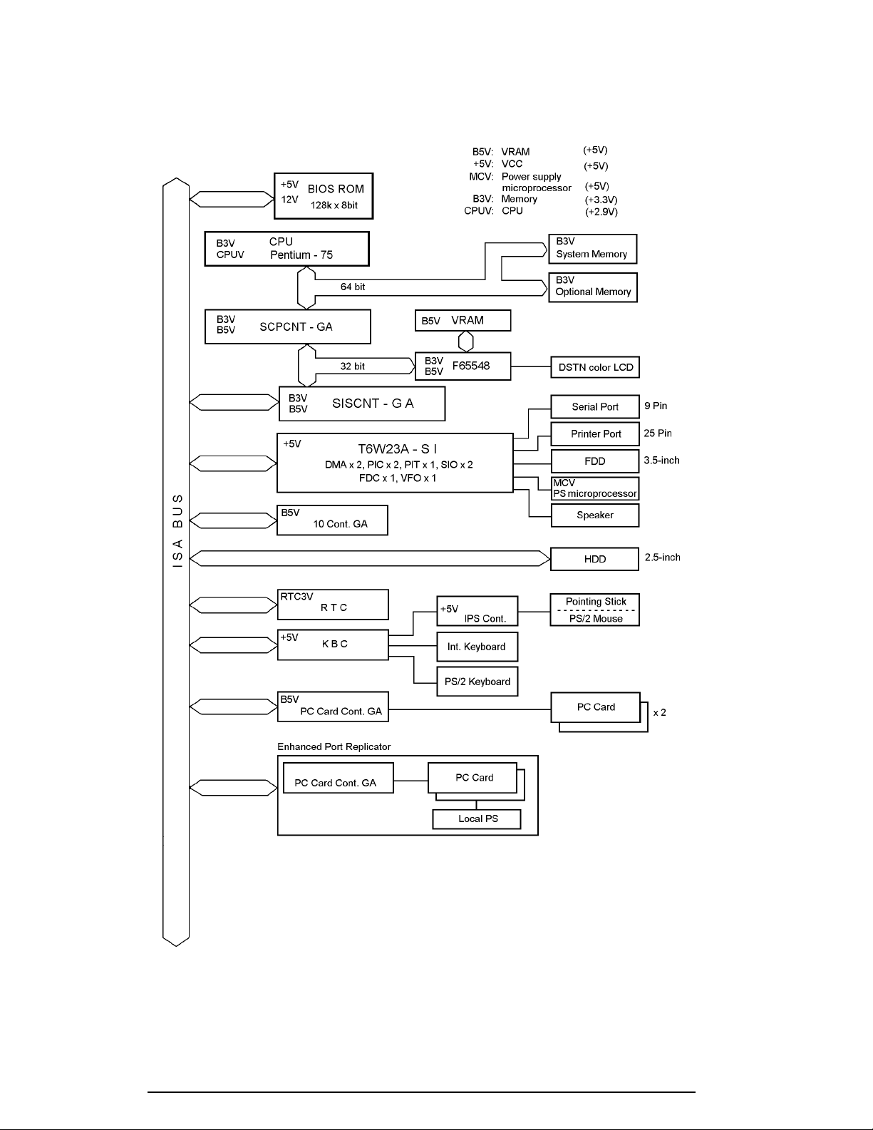
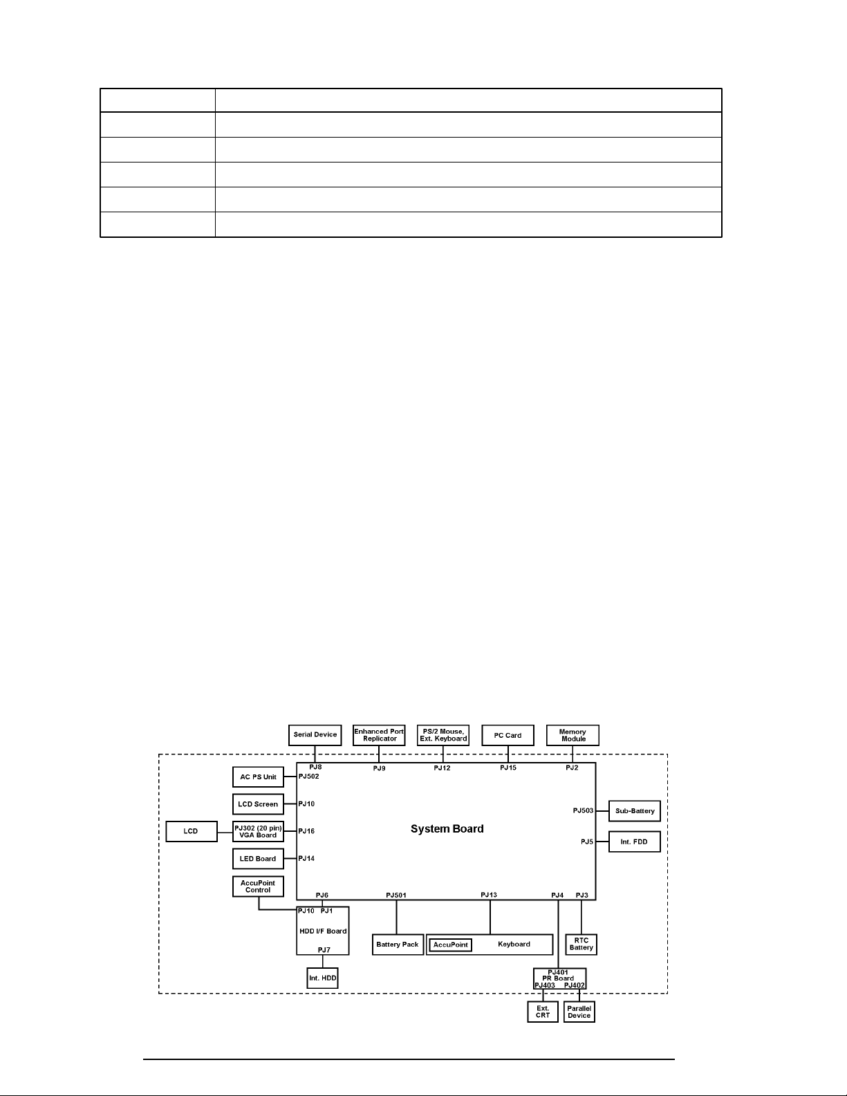
1.2 System Unit Block Diagram
Figure 1-3 is a block diagram of the system unit.
Figure 1-3 System board block diagram

100CS 1-5
The system board is composed of the following major components:
❑ Microprocessor
One Pentium processor with VRT 64-bit microprocessor
Pentium processor operates at 75 MHz and 3.3/2.9 volts
The math co-processor and 16KB cache memory are integrated into Pentium
❑ Standard RAM
8 MB, four 1Mx16-bit chips
3.3 volt operation
No parity bit
Access time 70 ns
Data transfer is 64-bit width
EDO (extended data output) supported
❑ BIOS ROM (Flash EEPROM)
128 KB (one 128Kx8-bit chip) memory
64 KB in the ROM are used for system BIOS
48 KB in the ROM are used for VGA BIOS
16 KB in the ROM are reserved
Access time 150 ns
Data transfer is 8-bit width
❑ Video RAM
1 MB (Two 256Kx16-bit DRAM)
5 volt operation
❑ Optional memory
One expansion memory slot is available for 8, 16, and 32 MB memory modules, which
consist of 1 MBx16-bit chips
Total maximum memory size is 40 MB (if a 32 MB memory module is installed)
3.3 volt operation
No parity bit
Access time 60 ns
Data transfer is 64-bit width
EDO (extended data output) supported
❑ One super integration (SI)
The following components:
- Two DMACs 82C37 equivalent
- Two PICs 82C59 equivalent
- Two SIOs 16550 equivalent (One SIO is not used)
- Two UARTs 16550 equivalent
- One PIT 82C54 equivalent
- One FDC TC8565 equivalent
- One VFO TC8568 equivalent
- One I/O port decoder
- One SIO port control
- One printer port control supported ECP
- One FDD control
- One speaker control
- One power communication control

1-6 100CS
❑ System Controller Gate Array (SCPCNT-GA)
This gate array has the following functions:
• CPU control
- SMI control
- CPU clock control
• Memory control
- 64-bit bus memory control
- 32-bit bus memory control
• Bus control
- 64-bit data bus <==>32-bit data bus
- 32-bit local bus control
• Address latch control
• I/O register control
• Processing speed control
❑ ISA Bus Controller Gate Array (SISCNT3-GA)
This gate array has the following functions:
• Bus control
- 32-bit data bus <==> 16-bit data bus
- ISA bus interface control
- ISA bus access control
- DMAC control
- DMA address generation
- I/O control
- Suspend/Resume sequence
• Memory control
- ISA bus interface control
- Refresh address generation
• I/O register control
• Suspend/Resume sequence
❑ PC Card Controller Gate Array (PCMCIA CNT-GA)
This gate array has the following functions:
• PCMCIA memory card control
• PCMCIA I/O card control
❑ I/O Controller Gate Array (IOCNT-GA)
This gate array has the following functions:
• Internal Communication controller
- KBC, main CPU communication register file
- KBC interrupt controller
- KBC communication controller
- I
2
C bus control (Not used)
• Others
- Speaker volume adjust PWM control
- Sound board interface (Not used)
- BIOS-ROM interface
- SMI control
- IrDA (SIR) control (Not used)

100CS 1-7
❑ Video Controller
C&T F65548 is used.
This video controller controls internal DSTN color LCD and external SVGA compat-
ible CRT.
❑ Keyboard Controller (KBC)
One M38802M4 chip is used.
This KBC includes the keyboard scan controller and keyboard interface controller.
The KBC controls the internal keyboard, external keyboard, PS/2 mouse.
❑ Real Time Clock (RTC)
One T9934 chip is used.
The T9934 has 128 bytes of memory. Fourteen bytes of memory are used for the
calendar and clock. The remaining 114 bytes are used for the system configuration
data.
1-8 100CS
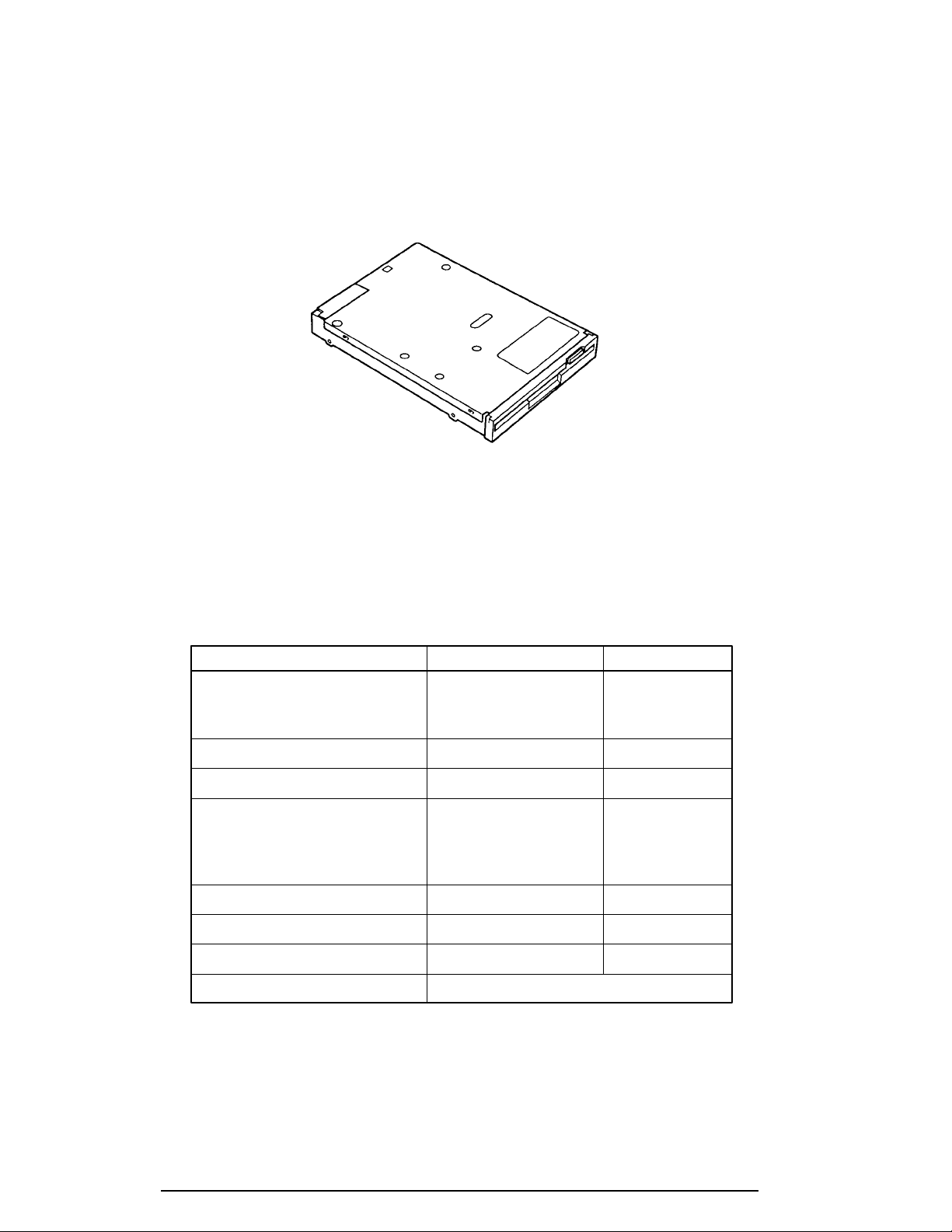
1.3 3.5-inch Floppy Disk Drive
The 3.5-inch FDD is a thin, high-performance reliable drive that supports 720-KB (formatted)
2DD and 1.44-MB (formatted) 2HD 3.5-inch floppy disks.
The FDD is shown in figure 1-4.
Figure 1-4 3.5-inch FDD
The specifications for the FDD are listed in table 1-1.
Table 1-1 3.5-inch FDD specifications
Item 2-MB mode 1-MB mode
Storage capacity (KB)
Unformatted 2,000 *1 1,000 *2
Formatted 1,311 655
Number of heads 2 2
Number of cylinders 80 80
Access time (ms)
Track to track 3 3
Average 181 181
Head settling time 15 15
Recording track density (tpi) 135 135
Data transfer rate (Kbps) 500 250
Rotation speed (rpm) 300 300
Recording method Modified Frequency Modulation (MFM)
*1:32 sector/track (256bytes per sector)
*2:16 sector/track (256bytes per sector)
100CS 1-9
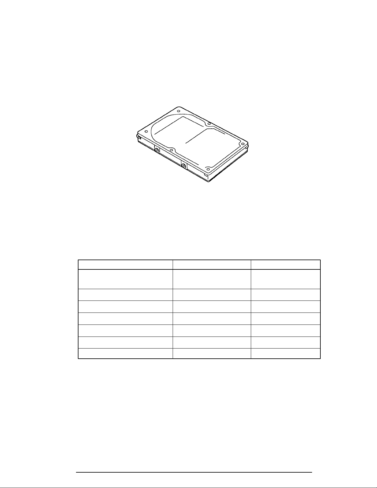
1.4 2.5-inch Hard Disk Drive
The HDD is a random access non-volatile storage device. It has a non-removable 2.5-inch
magnetic disk and mini-winchester type magnetic heads.
The computer supports the 520 MB.
The HDD is shown in figure 1-5.
Figure 1-5 2.5inch HDD
Specifications for the HDD are listed in table 1-2.
Table 1-2 2.5-inch HDD specifications
Items Toshiba MK1924FCV IBM DBOA-2528
Storage capacity (million byte)
Formatted 528 528
Number of disks 2 2
Data heads 4 3
Data surfaces 4 4
Bytes per sector 512 512
Rotation speed (rpm) 4200 4000
Recording method 8-9 RLL 1-7 RLL
1-10 100CS
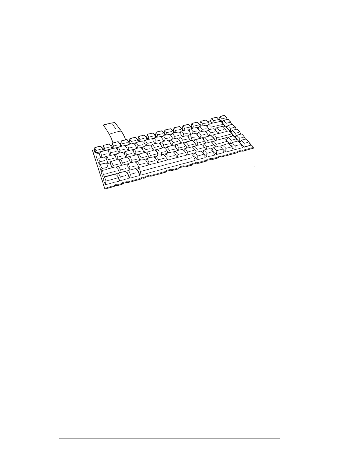
1.5 Keyboard
The 82-(USA) or 84-(European) keyboard is mounted on the computer’s system unit. The
keyboard is connected to the keyboard controller on the system board through a 25-pin flat
cable. The computer pointer control stick, located in the center of the keyboard, provides
convenient control of the cursor without requiring desk space for a mouse. The keyboard is
shown in figure 1-6.
See Appendix E for optional keyboard configurations.
Figure 1-6 Keyboard
100CS 1-11
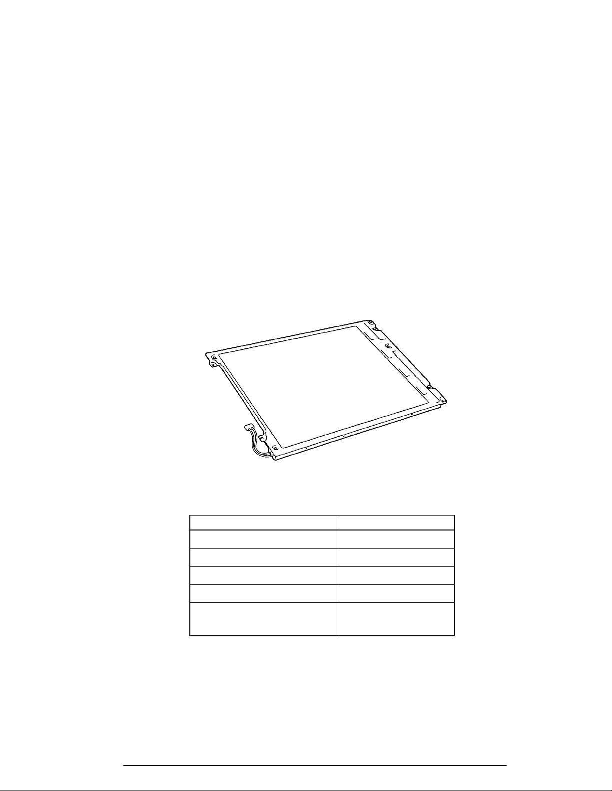
1.6 DSTN Color LCD
The DSTN Color Liquid Crystal Display (LCD) contains an LCD module, a Fluorescent
Lamp (FL), and an FL inverter board.
1.6.1 DSTN Color LCD Module
The DSTN color LCD is backlit and supports 640 x 480 pixels with a Video controller. This
video controller includes the functions of Video Graphics Array (VGA). The built-in display
controller supports 640 x 480 resolution with 64k colors capability on the internal LCD and
up to 1024 x 768 resolution with 256 colors on an external CRT.
The LCD receives vertical and horizontal synchronizing signals, 16-bit data signal, 8-bit upper
block data signal, 8-bit lower block data signal, and has a shift clock for data transmission.
All signals are CMOS-level compatible.
The DSTN LCD is shown in figure 1-7. The specifications for the LCD are listed in table 1-3.
Figure 1-7 DSTN color LCD
Table 1-3 DSTN color LCD specifications
Item Specifications
Number of Dots (dots) 640x480
Dot pitch (mm) 0.33x0.33
Display area (mm) 217.2 (W)x164.4 (H)
Contrast (Typically) 20:1
FL current (mA) 5.0/3.0
(Bright/Semi-bright)
1-12 100CS
1.6.2 DSTN Color Fluorescent Lamp (FL) Inverter Board
The FL inverter board supplies high frequency current to light the LCD’s Fluorescent Lamp.
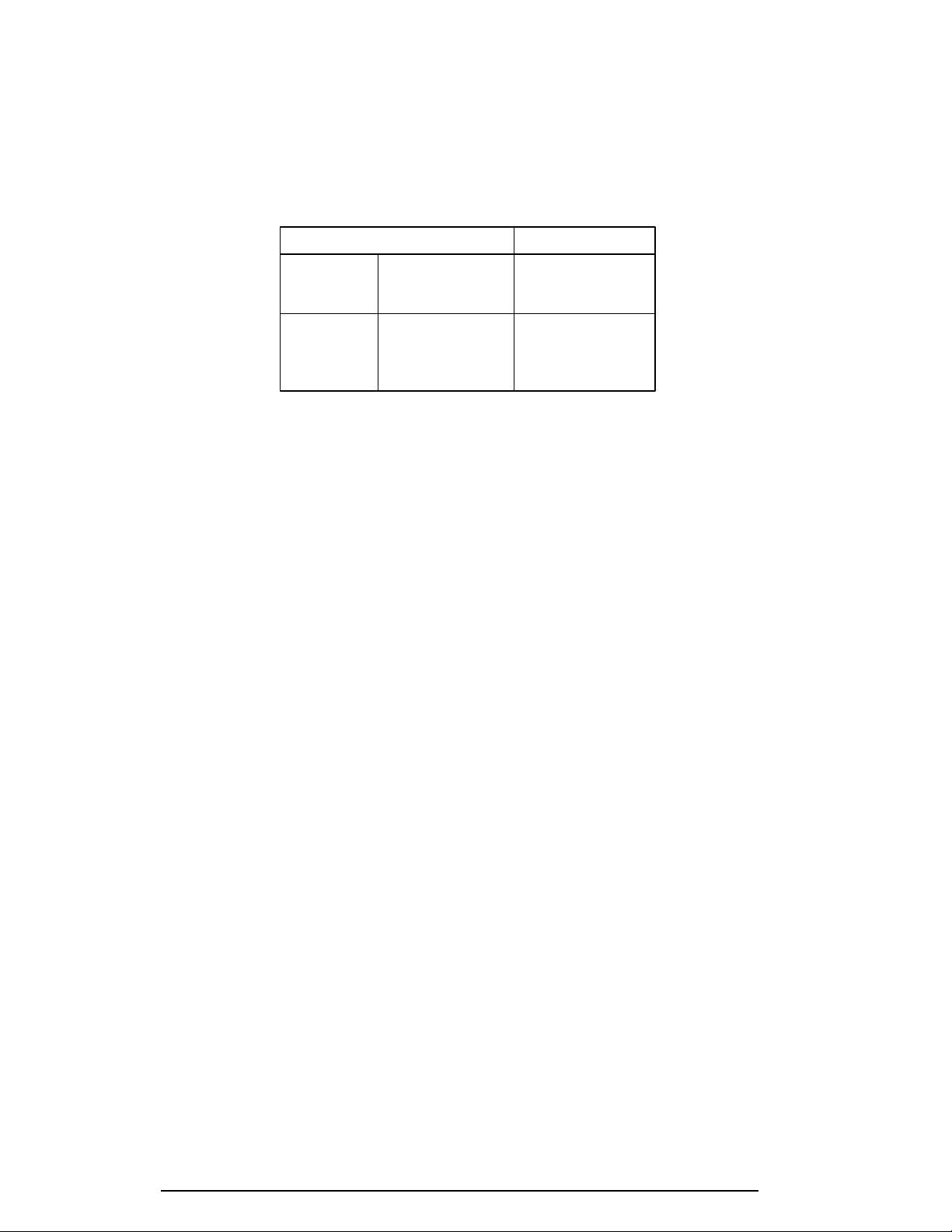
The specifications for the FL inverter are listed in table 1-4.
Table 1-4 DSTN color FL inverter board specifications
Item Specifications
Input Voltage (V) 4 to 5.5
Power (W) 4.25
Output Voltage (Vrms) 1,100
Current (mA) 5.0/3.0
(Bright/Semi-bright)
100CS 1-13
1.7 Power Supply
The power supply provides five kinds of voltages to the system board. The power supply has
one microprocessor, operates at 500 KHz, and performs the following functions:
1. Determines if the AC cable or battery is connected to the computer.
2. Detects AC output and circuit malfunctions.
3. Controls the LED icon and speaker.
4. Turns the battery charging system on and off and detects a fully charged battery.
5. Determines if the power can be turned on and off.
6. Provides more accurate detection of a low battery.
7. Calculates the remaining battery capacity.
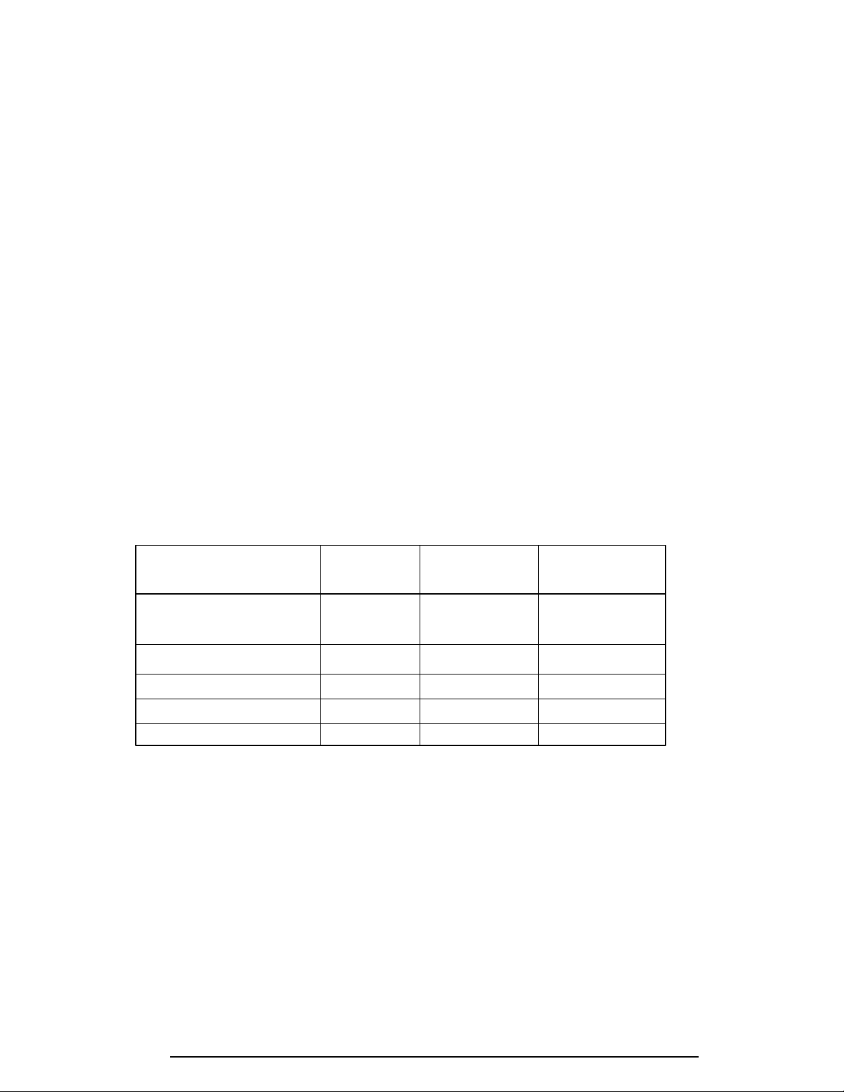
The power supply output rating is specified in table 1-5.
Table 1-5 Power supply output rating
DC Regulation
Use for Name voltage tolerance
(%)
System logic, FDD, HDD, VCC +5 ±5
Display
CPU CPUV +2.9 ±5
Flash ROM, PCMCIA 12V +12 ±5
CPU, RAM, GA B3V +3.3 ±0.3V
VRAM, GA B5V +4.7 ±5

1-14 100CS
1.8 Batteries
The computer has three types of batteries:
❑ Main battery pack
❑ Backup battery
❑ Real Time Clock (RTC) battery
Battery specifications are listed in table 1-6.
Table 1-6 Battery specifications
Battery name Material Output voltage Capacity
Main battery Nickel Metal Hydride 12 V 2,600 mAH
Backup battery Nickel Metal Hydride 7.2 V 110 mAH
RTC battery Nickel Metal Hydride 3.6 V 30 mAH
1.8.1 Main Battery
The removable main battery pack is the computer’s main power source when the AC power
cord is not attached. The main battery recharges the backup battery. The backup and main
battery maintain the state of the computer when you enable AutoResume.
❏ Battery Icon
The Battery icon is located on top of the back rim of the computer. The icon shows
the status of the removable battery pack.
The status of each can be determined by color:
Orange The AC power cord is connected and charging the battery with the
power off.
Green The AC power cord is connected and the battery is fully charged
whether the power is on or off.
Blink orange The battery is low. The AC power cord must be connected to recharge
the battery.
No light Under any other conditions, the LED does not light.
100CS 1-15
1.8.2 Battery Charging Control
Battery charging is controlled by a power supply microprocessor that is mounted on the
power supply. The microprocessor controls whether the charge is on or off and detects a full
charge when the AC power cord and battery are attached to the computer. The system
charges the battery using quick charge or trickle charge.
❏ Quick Battery Charge
When the AC power cord is attached, there are two types of charge: quick charge
when the system is powered off and trickle charge when the system is powered on.
Table 1-7 Time required for quick charges
Power Charging time
Power off About 2.5 hours
Power on Trickle charge
If one of the following occurs, the battery quick-charge process stops:
1. The battery becomes fully charged.
2. The battery is removed.
3. The battery or AC output voltage is abnormal.
4. The charge current is abnormal.
5. The fixed time limit for quick charge is exceeded.
❏ Trickle Battery Charge
When the main battery is fully charged and the AC power cord is attached, the power
supply microprocessor automatically changes from quick charge to trickle charge.
1-16 100CS
1.8.3 Backup Battery
The backup battery maintains data for AutoResume. The power source used to back up the
AutoResume data is determined according to the following priority:
AC power > Main battery > Backup battery
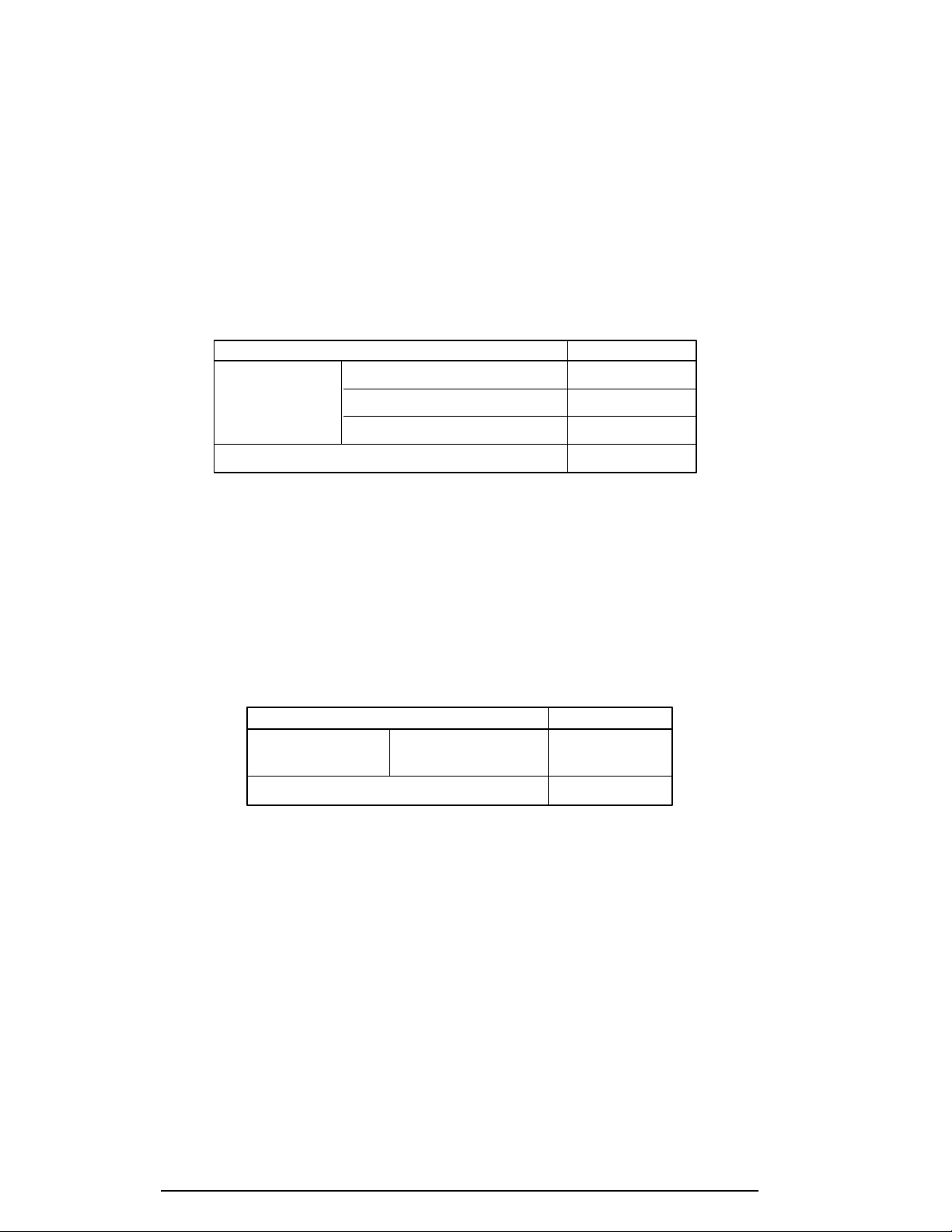
The backup battery is charged by the main battery or AC power cord. Table 1-8 shows the
charging time and data preservation period of the backup battery.
Table 1-8 Backup battery charging/data preservation time
Item Time
Charging Time Power On 20 H
Power Off (with AC power) 20 H
Power Off (without AC power) Doesn’t charge
Data preservation period (full charge) 5 H
1.8.4 RTC Battery
The RTC battery provides power to keep the current date, time, and other setup information
in memory while the computer is turned off. Table 1-9 shows the charging time and data
preservation period of the RTC battery.
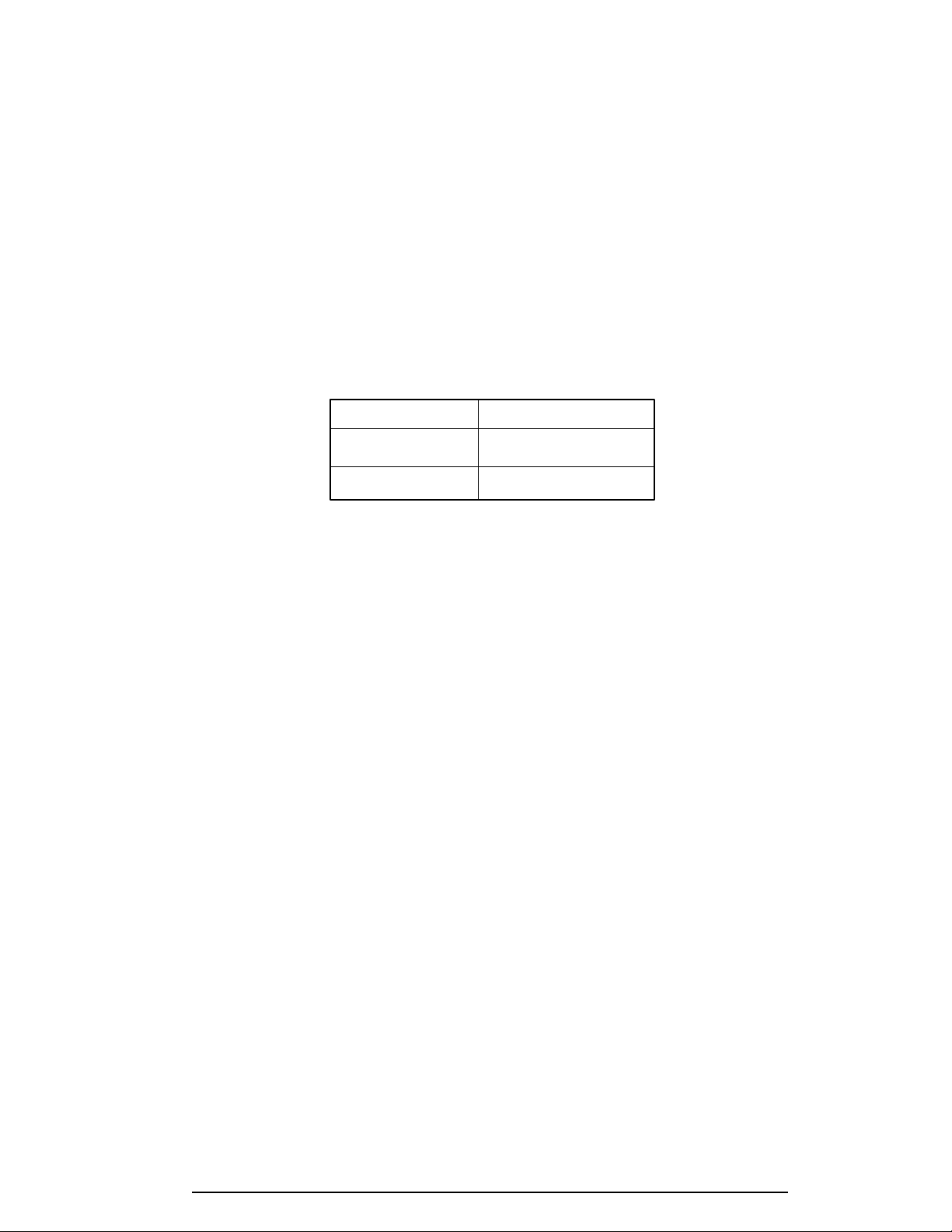
Table 1-9 RTC battery charging/data preservation time
Item Time
Charging Time With AC power 48 H
or main battery
Data preservation period (full charge) 1 month

100CS 2-1
2.1 Troubleshooting
Chapter 2 describes how to determine if a Field Replaceable Unit (FRU) in the computer is
causing the computer to malfunction. The FRUs covered are:
1. System Board(s)
2. VGA Board
3. HDD I/F Board
4. Floppy Disk Drive
5. Hard Disk Drive
6. Keyboard
7. Display
The Diagnostics Disk operations are described in Chapter 3 and detailed replacement proce-
dures are given in Chapter 4.
The following tools are necessary for implementing the troubleshooting procedures:
1. Diagnostics disk
2. Phillips screwdriver
3. Toshiba MS-DOS system disk(s)
(You must install the following onto the disk: SYS.COM, FORMAT.COM,
FDISK.COM and FDISK.EXE)
4. 2DD or 2HD formatted work disk for floppy disk drive testing
5. Cleaning kit for floppy disk drive troubleshooting
6. RS-232-C wraparound connector
7. Printer wraparound connector
8. Multimeter
9. External CRT
10. PS/2 or compatible keyboard
11. PS/2 or compatible mouse
12. Serial port wraparound connector
13. PC card wraparound card

2-2 100CS
2.2 Troubleshooting Flowchart
Use the flowchart in figure 2-1 as a guide for determining which troubleshooting procedures
to execute. Before going through the flowchart steps, do the following:
❑ Verify with the customer that Toshiba MS-DOS is installed on the hard disk. Non-
Toshiba operating systems can cause the computer to malfunction.
❑ Make sure all optional equipment is disconnected from the computer.
❑ Make sure the floppy disk drive is empty.

100CS 2-3
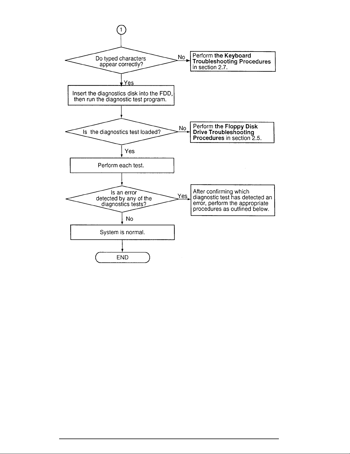
Figure 2-1 Troubleshooting flowchart (1/2)
2-4 100CS
Figure 2-1 Troubleshooting flowchart (2/2)
If the diagnostics program cannot detect an error, the problem may be intermittent. The
Running Test program should be executed several times to isolate the problem. Check the
Log Utilities function to confirm which diagnostic test detected an error(s), then perform the
appropriate troubleshooting procedures as follows:
1. If an error is detected on the system test, memory test, display test, ASYNC test,
printer test, or real timer test, perform the system board troubleshooting proce-
dures in section 2.4.
2. If an error is detected on the floppy disk test, perform the floppy disk drive
troubleshooting procedures in section 2.5.
3. If an error is detected on the hard disk test, perform the hard disk drive
troubleshooting procedures in section 2.6.
4. If an error is detected on the keyboard test, perform the keyboard troubleshooting
procedures in section 2.7.
5. If an error is detected on the display test, perform the display troubleshooting
procedures in section 2.8.

100CS 2-5
2.3 Power Supply Troubleshooting
The computer’s power supply controls many functions and components in the computer. To
determine if the power supply is functioning properly, start with Procedure 1 and continue
with the other Procedures as instructed. The procedures described in this section are:
Procedure 1: AC IN Icon Check
Procedure 2: Battery Icon Check
Procedure 3: AC PS Unit Replacement Check
Procedure 1 AC IN Icon Check
The AC PS unit converts AC power to DC power and contains a charging circuit which
charges the computer’s batteries. The AC power cord connects to the AC IN socket connec-
tor on the back side of the computer. When the AC power cord is connected to the 100CS,
the AC PS unit charges the batteries.
The AC IN icon displays whether or not the AC power cord is connected and supplying
power.
When the AC IN icon is green, the AC power cord is connected and supplying power to the
computer.
If the AC IN icon does not light, the AC power cord is not supplying power to the computer
or the AC power cord is not attached to the computer. Go to Check 1.
If the AC IN icon is flashing orange, the AC power cord’s voltage supply is abnormal or the
power supply is not functioning properly. Go to Check 1.
If any of the above indicator conditions are abnormal, make sure the icon lights are not burned
out before performing the following checks:
Check 1 Make sure the correct AC power cord is firmly plugged into the AC IN socket on
the back of the computer.
Check 2 If the AC IN icon flashes orange when the AC power cord is connected, output
voltage is abnormal. Connect a new AC power cord and turn the computer on
again to verify the indicator condition.
Check 3 The battery pack may be malfunctioning. Replace the battery pack with a new one
and turn the computer on again. If the problem still exists, go to Procedure 2.

2-6 100CS
Procedure 2 Battery Icon Check
The Battery icon shows the battery charging status. The Battery icon glows orange when the
AC power cord is charging the computer’s battery pack.
If the Battery icon glows green, the AC power cord is connected and the battery is fully
charged.
If the Battery icon glows orange, the AC power cord is connected and the battery is being
charged.
If the Battery icon does not glow, go to Check 1.
Check 1 Make sure the AC power cord is firmly plugged into the AC IN socket and wall
outlet. If these cables are connected correctly, go to Check 2.
Check 2 Make sure the battery pack is installed in the computer correctly. If the battery
pack is installed correctly, go to Check 3.
Check 3 Remove the battery pack and check that the battery terminal is clean and not bent.
If the terminal appears dirty, clean it gently with a cotton swab dipped in alcohol.
If the terminal looks bent or damaged, replace the system board.
If the battery terminal is clean and not bent, go to Check 4.
Check 4 Connect a new AC power cord. If the Battery icon still does not glow, go to
Check 5.
Check 5 Install a new battery pack. If the Battery icon still does not glow, go to Procedure
3.
Procedure 3 AC PS Unit Replacement Check
The system board incorporates the power supply. Power is supplied to the system board
through the AC IN plug located on the AC PS unit. The AC PS unit may be damaged, refer
to chapter 4 for instructions on how to disassemble the computer, and then perform the
following checks:
Check 1 Replace the AC PS unit with a new one and restart the system. If the system is
still not functioning properly, perform Check 2.
Check 2 Replace the system board with a new one and restart the system. If the problem
still exists, other FRUs may be damaged.

100CS 2-7
2.4 System Board and HDD I/F Board Troubleshooting
This section describes how to determine if the system board and sound board are defective or
not functioning properly. Start with Procedure 1 and continue with the other procedures as
instructed. The procedures described in this section are:
Procedure 1: Message Check
Procedure 2: Printer Port LED Check on Boot Mode
Procedure 3: Printer Port LED Check on Resume Mode
Procedure 4: Diagnostic Test Program Execution Check
Procedure 5: Replacement Check
Procedure 1 Message Check
When the power is turned on, the system performs the Initial Reliability Test (IRT) installed in
the BIOS ROM. The IRT tests each IC on the system board and initializes it.
❑ If an error message is shown on the display, perform Check 1.
❑ If there is no error message, go to Procedure 2.
❑ If the Toshiba MS-DOS is properly loaded, go to Procedure 3.
Check 1 If one of the following error messages is displayed on the screen, press the F1 key
as the message instructs. These errors occur when the system configuration
preserved in the RTC memory (CMOS type memory) is not the same as the actual
configuration or when the data is lost.
If you press the F1 key as the message instructs, the system configuration in the
RTC memory configuration is set to the default setting. If error message (b)
appears often when the power is turned on, replace the RTC battery. If any other
error message is displayed, perform Check 2.
(a) *** Bad HDD type ***
Check system. Then press [F1] key ......
(b) *** Bad RTC battery ***
Check system. Then press [F1] key ......
(c) *** Bad configuration ***
Check system. Then press [F1] key ......
(d) *** Bad memory size ***
Check system. Then press [F1] key ......
(e) *** Bad time function ***
Check system. Then press [F1] key ......
(f) *** Bad check sum (CMOS) ***
Check system. Then press [F1] key ......
(g) *** Bad check sum (ROM) ***
Check system. Then press [F1] key ......

2-8 100CS
Check 2 If the following error message is displayed on the screen, press any key as the
message instructs.
This error message appears when data stored in RAM under the resume function is
lost because the battery has become discharged or the system board is damaged.
Go to Procedure 3.
WARNING: RESUME FAILURE.
PRESS ANY KEY TO CONTINUE.
If any other message appears, perform Check 3.
Check 3 The IRT checks the system board. When the IRT detects an error, the system
stops or an error message appears.
If one of the following error messages (1) through (19), (20) or (27) is displayed,
replace the system board.
If error message (20) is displayed, go to the Keyboard Troubleshooting Proce-
dures in section 2.7.
If error message (21), (22) or (23) is displayed, go to the HDD Troubleshooting
Procedures in section 2.6.
If error message (24) or (25) is displayed, go to the FDD Troubleshooting Proce-
dures in section 2.5.
(1) BIOS is damaged
(2) PIT ERROR
(3) MEMORY REFRESH ERROR
(4) TIMER CH.2 OUT ERROR
(5) FIRST 64KB MEMORY ERROR
(6) CMOS CHECKSUM ERROR
(7) CMOS BAD BATTERY ERROR
(8) FIRST 64KB MEMORY ERROR
(9) FIRST 64KB MEMORY PARITY ERROR
(10) VRAM ERROR
(11) SYSTEM MEMORY ERROR
(12) SYSTEM MEMORY PARITY ERROR
(13) EXTENDED MEMORY ERROR
(14) EXTENDED MEMORY PARITY ERROR
(15) DMA PAGE REGISTER ERROR
(16) DMAC #1 ERROR
(17) DMAC #2 ERROR
(18) PIC #1 ERROR
(19) PIC #2 ERROR
(20) KBC ERROR
(21) HDC ERROR
(22) HDD #0 ERROR
(23) HDD #1 ERROR
(24) NO FDD ERROR
(25) FDC ERROR
(26) TIMER INTERRUPT ERROR
(27) RTC UPDATE ERROR
100CS 2-9
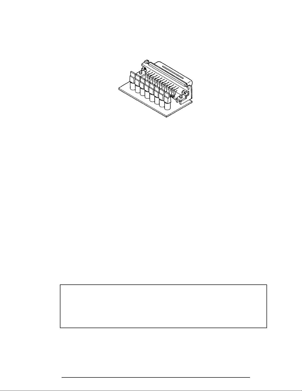
Procedure 2 Printer Port LED Check on Boot Mode
The printer port LED displays the IRT status and test status by turning lights on and off as an
eight-digit binary value for boot mode. Figure 2-2 shows the printer port LED.
Figure 2-2 Printer port LED
To use the printer port LED follow these steps:
1. Turn the computer on, then set to boot mode.
2. Turn the computer off.
3. Plug the printer port LED into the computer’s parallel port.
4. Hold the space bar down and turn the computer on.
5. Read the LED status from left to right as you are facing the back of the computer.
6. Convert the status from binary to hexadecimal notation.
7. If the final LED status is FFh (normal status), go to Procedure 3.
8. If the final LED status matches any of the test status values in table 2-1, perform
Check 1.
NOTE: If an error condition is detected by the IRT test, the printer port LED
displays an error code after the IRT test ends. For example, when the printer
port LED displays 1F and halts, the IRT test has already completed the Display
initialization. In this instance, the IRT indicates an error has been detected
during the system memory test.
2-10 100CS
Table 2-1 Printer port LED boot mode status (1/2)
LED status Test item Message
01H KBC initialization
ROM checksum test BIOS is damaged! .....
02H Special register initialization
PIT test PIT ERROR
PIT initialization —
PIT function check MEMORY REFRESH ERROR
TIMER CH.2 OUT ERROR
03H CMOS check CMOS CHECKSUM ERROR
CMOS BAD BATTERY ERROR
KB initialization KBC ERROR
04H Initialization of —
memory configuration
05H SM-RAM check —
06H Self test check —
Read of Power Supply —
information
07H ROM/RAM copy —
08H Initialization of internal VGA —
0AH First 64 KB memory test FIRST 64KB MEMORY ERROR
FIRST 64KB MEMORY PARITY ERROR
0BH System memory initialization —
0CH System initialization —
0DH Interrupt vector initialization —
18H PIC initialization —
1FH Display initialization VRAM ERROR
25H System memory test SYSTEM MEMORY ERROR
SYSTEM MEMORY PARITY ERROR
30H Extended memory test EXTENDED MEMORY ERROR
EXTENDED MEMORY PARITY ERROR
40H DMA page register test DMA PAGE REGISTER ERROR
41H DMAC test DMAC #X ERROR
42H DMAC initialization —
4AH PIC test PIC #X ERROR
50H Mouse initialization —
55H KBC initialization KBC ERROR
60H HDD initialization HDC ERROR/HDD #0 ERROR
65H FDD initialization FDC ERROR/NO FDD ERROR
70H Printer initialization —
80H SIO initialization —
90H Timer initialization RTC UPDATE ERROR
TIMER INTERRUPT ERROR
A0H NDP initialization —

100CS 2-11
Table 2-1 Printer port LED boot mode status (2/2)
LED status Test item Message
A6H Initialization of expansion ROM —
C0H Password check —
FFH Setup boot check *** Bad xxxx xxxx ***
Check system. Then press [F1] key.
FFH Boot load —
Check 1 If the following error codes are displayed, go to Procedure 5.
01h, 02h, 03h, 04h, 05h, 06h, 07h, 08h, 0Ah, 0Bh, 0Ch, 0Dh, 18h, 1Fh, 25h,
30h, 40h, 41h, 42h, 4Ah, 65h, 70h, 80h, 90h, A0h, A6h, C0h, FFh
Check 2 If error code 50h is displayed, go to the Keyboard Troubleshooting procedures in
Section 2.7.
Check 3 If error code 55h is displayed, go to the HDD Troubleshooting Procedures in
Section 2.6.
Check 4 If error code 60h is displayed, go to the FDD Troubleshooting Procedures in
Section 2.5.
Procedure 3 Printer Port LED Check on Resume Mode
The printer port LED displays the IRT status and test status by turning lights on and off as an
eight-digit binary value for resume mode.
To use the printer port LED follow these steps:
1. Turn the computer on, then set to resume mode.
2. Turn the computer off.
3. Plug the printer port LED into the computer’s parallel port.
4. Turn the computer on.
5. Read the LED status from left to right as you face the back of the computer.
6. Convert the status from binary to hexadecimal notation.
7. If the final LED status is FFh (normal status), go to Procedure 4.
8. If the final LED status matches any of the test status values in table 2-2, perform
Procedure 5.
2-12 100CS
Table 2-2 Printer port LED resume mode error status
Error status Meaning of status
F1H RAM BIOS error.
F2H The system has optional ROM, or optional card (CGA, MDA).
F5H Main memory checksum error.
F6H Video RAM checksum error.
F7H Extended memory checksum error.
Procedure 4 Diagnostic Test Program Execution Check
Execute the following tests from the Diagnostic Test Menu. Refer to chapter 3, Tests and
Diagnostics , for more information on how to perform these tests.
1. System test
2. Memory test
3. Printer test
4. ASYNC test
5. Real Timer test
6. PCMCIA test
If an error is detected during these tests, go to Procedure 5 .
Procedure 5 Replacement Check
The system board or the HDD I/F board may be damaged. Disassemble the computer follow-
ing the steps described in chapter 4, Replacement Procedures , and perform the following
checks:
Check 1 Replace the system board with a new one. Refer to chapter 4 for instructions on
how to remove and replace the system board.
Check 2 Replace the HDD I/F board with a new one. Refer to chapter 4 for instructions on
how to remove and replace the sound board.

100CS 2-13
2.5 Floppy Disk Drive Troubleshooting
This section describes how to determine if the 3.5-inch floppy disk drive is functioning prop-
erly. Perform the steps below starting with Procedure 1 and continuing with the other
procedures as required.
Procedure 1: FDD Head Cleaning Check
Procedure 2: Diagnostic Test Program Execution Check
Procedure 3: Connector Check and Replacement Check
Procedure 1 FDD Head Cleaning Check
FDD head cleaning is one option available in the Diagnostic Program . Detailed operation is
given in chapter 3, Tests and Diagnostics .
After Toshiba MS-DOS loads, run the Diagnostic Program and then clean the FDD heads
using the cleaning kit. If the FDD still does not function properly after cleaning, go to Proce-
dure 2.
If the test program cannot be executed on the computer, go to Procedure 3.
2-14 100CS
Procedure 2 Diagnostic Test Program Execution Check
The Floppy Disk Drive Diagnostic Test program is stored on the Diagnostics Disk. After
loading Toshiba MS-DOS, run the diagnostic program. Refer to Chapter 3, Tests and Diag-
nostics, for more information about the diagnostics test procedures.
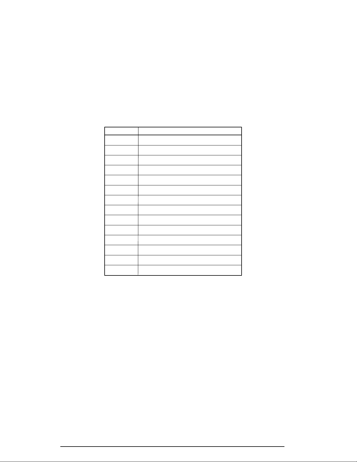
Floppy disk drive test error codes and their status names are described in table 2-3. Make
sure the floppy disk in the FDD is formatted correctly and that the write protect tab is dis-
abled. If any other errors occur while executing the FDD diagnostics test, go to Check 1.
Table 2-3 Floppy disk drive error code and status
Code Status
01h Bad command
02h Address mark not found
03h Write protected
04h Record not found
06h Media removed on dual attach card
08h DMA overrun error
09h DMA boundary error
10h CRC error
20h FDC error
40h Seek error
60h FDD not drive
80h Time out error (Not ready)
EEh Write buffer error
FFh Data compare error
Check 1 If the following message is displayed, disable the write protect tab on the floppy
disk. If any other message appears, perform Check 2.
Write protected
Check 2 Make sure the floppy disk is formatted correctly. If it is, go to Procedure 3.
 Loading...