


libretto u100
Table of contents
 Loading...
Toshiba Personal Computer
libretto U100
Maintenance Manual
TOSHIBA CORPORATION
File Number 960-520
[CONFIDENTIAL]

ii [CONFIDENTIAL] libretto U100 Maintenance Manual (960-520)
Copyright
© 2005 by Toshiba Corporation. All rights reserved. Under the copyright laws, this manual
cannot be reproduced in any form without the prior written permission of Toshiba. No patent
liability is assumed with respect to the use of the information contained herein.
Toshiba Personal Computer libretto U100 Maintenance Manual
First edition April 2005
Disclaimer
The information presented in this manual has been reviewed and validated for accuracy. The
included set of instructions and descriptions are accurate for the libretto U100 at the time of
this manual's production. However, succeeding computers and manuals are subject to
change without notice. Therefore, Toshiba assumes no liability for damages incurred
directly or indirectly from errors, omissions, or discrepancies between any succeeding
product and this manual.
Trademarks
IBM is a registered trademark and IBM PC is a trademark of International Business
Machines Corporation.
Intel, Intel SpeedStep and Pentium are trademarks or registered trademarks of Intel
Corporation or its subsidiaries in the United States and other countries/regions.
Windows and Microsoft are registered trademarks of Microsoft Corporation.
Bluetooth is a trademark owned by its proprietor and used by TOSHIBA under license.
OmniPass is the trademark of Softex Incorporated.
Other trademarks and registered trademarks not listed above may be used in this manual.
libretto U100 Maintenance Manual (960-520) [CONFIDENTIAL] iii
Preface
This maintenance manual describes how to perform hardware service maintenance for the
Toshiba Personal Computer libretto U100.
The procedures described in this manual are intended to help service technicians isolate
faulty Field Replaceable Units (FRUs) and replace them in the field.
SAFETY PRECAUTIONS
Four types of messages are used in this manual to bring important information to your
attention. Each of these messages will be italicized and identified as shown below.
DANGER: “Danger” indicates the existence of a hazard that could result in death or
serious bodily injury, if the safety instruction is not observed.
WARNING: “Warning” indicates the existence of a hazard that could result in bodily
injury, if the safety instruction is not observed.
CAUTION: “Caution” indicates the existence of a hazard that could result in property
damage, if the safety instruction is not observed.
NOTE: “Note” contains general information that relates to your safe maintenance
service.
Improper repair of the computer may result in safety hazards. Toshiba requires service
technicians and authorized dealers or service providers to ensure the following safety
precautions are adhered to strictly.
Be sure to fasten screws securely with the right screwdriver. If a screw is not fully
fastened, it could come loose, creating a danger of a short circuit, which could cause
overheating, smoke or fire.
If you replace the battery pack or RTC battery, be sure to use only the same model
battery or an equivalent battery recommended by Toshiba. Installation of the wrong
battery can cause the battery to explode.

iv [CONFIDENTIAL] libretto U100 Maintenance Manual (960-520)
The manual is divided into the following parts:
Chapter 1 Hardware Overview describes the libretto U100 system unit and each
FRU.
Chapter 2 Troubleshooting Procedures explains how to diagnose and resolve
FRU problems.
Chapter 3 Test and Diagnostics describes how to perform test and diagnostic
operations for maintenance service.
Chapter 4 Replacement Procedures describes the removal and replacement of the
FRUs.
Appendices The appendices describe the following:
Handling the LCD module
Board layout
Pin assignments
Display codes
Key layout
Wiring diagrams
BIOS Rewrite Procedures
EC/KBC Rewrite Procedures
Reliability

libretto U100 Maintenance Manual (960-520) [CONFIDENTIAL] v
Conventions
This manual uses the following formats to describe, identify, and highlight terms and
operating procedures.
Acronyms
On the first appearance and whenever necessary for clarification acronyms are enclosed in
parentheses following their definition. For example:
Read Only Memory (ROM)
Keys
Keys are used in the text to describe many operations. The key top symbol as it appears on
the keyboard is printed in boldface type.
Key operation
Some operations require you to simultaneously use two or more keys. We identify such
operations by the key top symbols separated by a plus (+) sign. For example, Ctrl + Pause
(Break) means you must hold down Ctrl and at the same time press Pause (Break). If
three keys are used, hold down the first two and at the same time press the third.
User input
Text that you are instructed to type in is shown in the boldface type below:
DISKCOPY A: B:
The display
Text generated by the computer that appears on its display is presented in the type face
below:
Format complete
System transferred

vi [CONFIDENTIAL] libretto U100 Maintenance Manual (960-520)
Table of Contents
Chapter 1 Hardware Overview
1.1 Features......................................................................................................................1-1
1.2 USB 3.5-inch Floppy Disk Drive ...........................................................................1-10
1.3 1.8-inch Hard Disk Drive......................................................................................... 1-11
1.4 Optical Drive............................................................................................................ 1-13
1.5 Keyboard.................................................................................................................. 1-17
1.6 LCD Module............................................................................................................ 1-18
1.7 Power Supply...........................................................................................................1-19
1.8 Batteries ...................................................................................................................1-21
1.9 AC adapter...............................................................................................................1-23
Chapter 2 Troubleshooting Procedures
2.1 Troubleshooting......................................................................................................... 2-1
2.2 Troubleshooting Flowchart........................................................................................2-2
2.3 Power Supply Troubleshooting .................................................................................2-6
2.4 System Board Troubleshooting ...............................................................................2-17
2.5 USB FDD Troubleshooting ..................................................................................... 2-32
2.6 HDD Troubleshooting ............................................................................................. 2-35
2.7 Keyboard Troubleshooting ...................................................................................... 2-40
2.8 Display Troubleshooting..........................................................................................2-42
2.9 Accupoint Troubleshooting ..................................................................................... 2-45
2.10 Modem Troubleshooting.......................................................................................... 2-47
2.11 LAN Troubleshooting..............................................................................................2-49
2.12 Sound Troubleshooting............................................................................................2-51
2.13 Bluetooth Troubleshooting......................................................................................2-53
2.14 Wireless LAN Troubleshooting............................................................................... 2-56
2.15 SD Card Slot Troubleshooting................................................................................. 2-59
2.16 Fingerprint sensor Troubleshooting......................................................................... 2-60
2.17 libretto DVD Dock Troubleshooting....................................................................... 2-67

libretto U100 Maintenance Manual (960-520) [CONFIDENTIAL] vii
Chapter 3 Tests and Diagnostics
3.1 The Diagnostic Test................................................................................................... 3-1
3.2 Executing the Diagnostic Test...................................................................................3-4
3.3 Setting of the hardware configuration .......................................................................3-9
3.4 Heatrun Test.............................................................................................................3-12
3.5 Subtest Names.......................................................................................................... 3-13
3.6 System Test..............................................................................................................3-15
3.7 Memory Test............................................................................................................3-17
3.8 Keyboard Test..........................................................................................................3-18
3.9 Display Test.............................................................................................................3-19
3.10 Floppy Disk Test......................................................................................................3-22
3.11 Printer Test...............................................................................................................3-24
3.12 Async Test ...............................................................................................................3-26
3.13 Hard Disk Test......................................................................................................... 3-27
3.14 Real Timer Test........................................................................................................3-30
3.15 NDP Test.................................................................................................................. 3-32
3.16 Expansion Test.........................................................................................................3-33
3.17 CD-ROM/DVD-ROM Test .....................................................................................3-35
3.18 Error Code and Error Status Names.........................................................................3-36
3.19 Hard Disk Test Detail Status ...................................................................................3-39
3.20 ONLY ONE TEST................................................................................................... 3-41
3.21 Head Cleaning.......................................................................................................... 3-48
3.22 Log Utilities.............................................................................................................3-49
3.23 Running Test............................................................................................................3-51
3.24 Floppy Disk Drive Utilities......................................................................................3-52
3.25 System Configuration .............................................................................................. 3-57
3.26 Wireless LAN Test Program (Atheros) ...................................................................3-59
3.27 LAN/Modem/Bluetooth/IEEE1394 Test Program ..................................................3-66
3.28 Sound Test program.................................................................................................3-82
3.29 SETUP ..................................................................................................................... 3-88

viii [CONFIDENTIAL] libretto U100 Maintenance Manual (960-520)
Chapter 4 Replacement Procedures
4.1 General.......................................................................................................................4-1
4.2 Battery pack............................................................................................................... 4-8
4.3 PC card/SD card....................................................................................................... 4-10
4.4 Memory module....................................................................................................... 4-12
4.5 Keyboard.................................................................................................................. 4-14
4.6 Top cover assembly ................................................................................................. 4-17
4.7 Bluetooth module..................................................................................................... 4-21
4.8 FP Board .................................................................................................................. 4-23
4.9 Accupoint.................................................................................................................4-24
4.10 MDC/SD board........................................................................................................ 4-26
4.11 Kill switch cover/Wireless LAN card......................................................................4-29
4.12 System board/DC-IN jack........................................................................................ 4-31
4.13 RTC battery.............................................................................................................. 4-34
4.14 Fan heat sink............................................................................................................ 4-36
4.15 HDD.........................................................................................................................4-38
4.16 LAN•Modem jack/DK board................................................................................... 4-42
4.17 PC board...................................................................................................................4-44
4.18 LCD mask/LCD unit/BL board ............................................................................... 4-45
4.19 Harness assembly/Hinge..........................................................................................4-50
4.20 libretto DVD Dock...................................................................................................4-56

libretto U100 Maintenance Manual (960-520) [CONFIDENTIAL] ix
Appendices
Appendix A Handling the LCD Module ........................................................................... A-1
Appendix B Board Layout ................................................................................................ B-1
Appendix C Pin Assignments............................................................................................ C-1
Appendix D Keyboard Scan/Character Codes .................................................................. D-1
Appendix E Key Layout.....................................................................................................E-1
Appendix F Wiring Diagrams............................................................................................F-1
Appendix G BIOS Rewrite Procedures............................................................................. G-1
Appendix H EC/KBC Rewrite Procedures........................................................................ H-1
Appendix I Reliability........................................................................................................I-1

x [CONFIDENTIAL] libretto U100 Maintenance Manual (960-520)

[CONFIDENTIAL]
Chapter 1
Hardware Overview

1 Hardware Overview
1-ii [CONFIDENTIAL] libretto U100 Maintenance Manual (960-520)

1 Hardware Overview
libretto U100 Maintenance Manual (960-520) [CONFIDENTIAL] 1-iii
Chapter 1 Contents
1.1 Features.......................................................................................................................1-1
1.2 USB 3.5-inch Floppy Disk Drive ............................................................................1-10
1.3 1.8-inch Hard Disk Drive.........................................................................................1-11
1.4 Optical Drive............................................................................................................1-13
1.4.1 DVD-ROM & CD-R/RW Drive.........................................................1-13
1.4.2 DVD Super Multi Drive......................................................................1-15
1.5 Keyboard ..................................................................................................................1-17
1.6 LCD Module.............................................................................................................1-18
1.7 Power Supply............................................................................................................1-19
1.8 Batteries....................................................................................................................1-21
1.8.1 Main Battery .......................................................................................1-21
1.8.2 Battery Charging Control....................................................................1-22
1.8.3 RTC battery.........................................................................................1-22
1.9 AC adapter................................................................................................................1-23

1 Hardware Overview
1-iv [CONFIDENTIAL] libretto U100 Maintenance Manual (960-520)
Figures
Figure 1-1 Front of the computer..................................................................................... 1-4
Figure 1-2 System unit configuration.............................................................................. 1-5
Figure 1-3 System unit block diagram............................................................................. 1-6
Figure 1-4 USB 3.5-inch FDD....................................................................................... 1-10
Figure 1-5 1.8-inch HDD...............................................................................................1-11
Figure 1-6 DVD-ROM & CD-R/RW drive...................................................................1-13
Figure 1-7 DVD Super multi drive................................................................................ 1-15
Tables
Table 1-1 USB 3.5-inch FDD specifications ...............................................................1-10
Table 1-2 1.8-inch HDD dimensions ........................................................................... 1-11
Table 1-3 1.8-inch HDD specifications........................................................................1-12
Table 1-4 DVD-ROM & CD-R/RW drive dimensions................................................1-13
Table 1-5 DVD-ROM & CD-R/RW drive specifications............................................1-14
Table 1-6 DVD Super multi drive dimensions.............................................................1-15
Table 1-7 DVD Super Multi drive specifications ........................................................1-16
Table 1-8 LCD module specifications.......................................................................... 1-18
Table 1-9 Power supply output rating..........................................................................1-19
Table 1-10 Battery specifications................................................................................... 1-21
Table 1-11 Time required for charges of main battery .................................................. 1-22
Table 1-12 RTC battery charging/data preservation time..............................................1-22
Table 1-13 AC adapter specifications............................................................................ 1-23

1.1 Features 1 Hardware Overview
libretto U100 Maintenance Manual (960-520) [CONFIDENTIAL] 1-1
1 Features
1.1 Features
The Toshiba libretto U100 Personal Computer uses extensive Large Scale Integration (LSI),
and Complementary Metal-Oxide Semiconductor (CMOS) technology extensively to provide
compact size, low power usage and high reliability. This computer incorporates the following
features and benefits.
Microprocessor
Intel Mobile Pentium-M
A 1.1/1.2GHz processor with a 400MHz external clock, 100MHz bus and
0.94/0.81V core operation.
Chipset
The libretto U100 is equipped with Intel Montara-GM+ (855GME), Intel ICH4-M and
Texas Instruments PCI7411.
Cache Memory
64KB (32kB Code+32KB Data) primary cache (in CPU) and 2MB secondary cache (in
CPU).
Memory
One DDR SO-DIMM slot is available for installation of PC2700 compatible 256, 512MB
or 1GB memory modules.
VRAM
64MB VRAM in Montara-GM+ (855GME) (North Bridge).
HDD
60GB internal drive of 1.8-inch, 8.0mm height or 30GB internal drive of 1.8-inch, 5.0mm
height.
USB FDD (option)
An optional USB FDD that supports 720KB/1.44MB format is prepared.
libretto DVD Dock (option)
A 9.0mm height CD-R/RW & DVD-ROM or DVD Super-Multi Drive can be mounted in
the optional libretto DVD Dock.

1 Hardware Overview 1.1 Features
1-2 [CONFIDENTIAL] libretto U100 Maintenance Manual (960-520)
Display
LCD
Built-in 7.2 inch, 16M colors, WXGA (1280×768 dots), thin type low temperature
poly- silicon TFT color display. Video controller is included in North Bridge chip.
External monitor
Supported via an RGB connector.
Keyboard
Keyboard has 82-key and supports Windows key.
AccuPoint
AccuPoint with two buttons is installed as a pointing device.
Batteries
The computer has two batteries: a rechargeable Lithium-Ion main battery pack (10.8V-
3400mAh) and Ni-MH RTC battery (2.4V-16mAH) (that backs up the Real Time Clock
and CMOS memory).
Universal Serial Bus (USB2.0)
Two USB ports are provided. The ports comply with the USB2.0 standard, which enables
data transfer speeds 40 times faster than USB1.1 standard.
PC card slot
A PC card slot (PCMCIA) accommodates one 5mm Type II card.
SD card slot
A SD card slot can accommodate Secure Digital flash memory cards with various
capacities.
Sound system
The sound system is equipped with the following features:
•
•
•
•
•
•
AC 97 Link
Sound CODEC: STAC9750
Built in stereo speaker
Volume control knob
Stereo Headphone jack
External microphone jack

1.1 Features 1 Hardware Overview
libretto U100 Maintenance Manual (960-520) [CONFIDENTIAL] 1-3
Internal modem
The internal modem is equipped as a modem daughter card (MDC).
The internal modem provides capability for data and fax communication and supports
V.90. For data reception it operates at 56,000bps and for data transmission it operates at
33,600bps. For fax transmission it operates at 14,400bps. The speed of data transfer and
fax depends on analog telephone line conditions. It has an RJ11 modem jack for
connecting to a telephone line.
Internal LAN
The computer is equipped with LAN circuits that support Ethernet LAN (10 megabits per
second, 10BASE-T) and Fast Ethernet LAN (100 megabits per second, 100 BASE-TX).
Wireless LAN
The internal wireless LAN supports Mini PCI Type III (802.11b/g).
Bluetooth
Bluetooth module can be equipped. This enables a communication to devices that support
Bluetooth Version 1.2/2.0. Adopting AFH (Adaptive Frequency Hopping), reduce the
interference with the wireless communication in 2.4GHz.
Fingerprint sensor
The computer is equipped with a fingerprint sensor and fingerprint authentication utility.
They enable only person who has registered his/her fingerprint to use the computer.
1 Hardware Overview 1.1 Features
The front of the computer is shown in Figure 1-1.
Figure 1-1 Front of the computer
1-4 [CONFIDENTIAL] libretto U100 Maintenance Manual (960-520)
1.1 Features 1 Hardware Overview
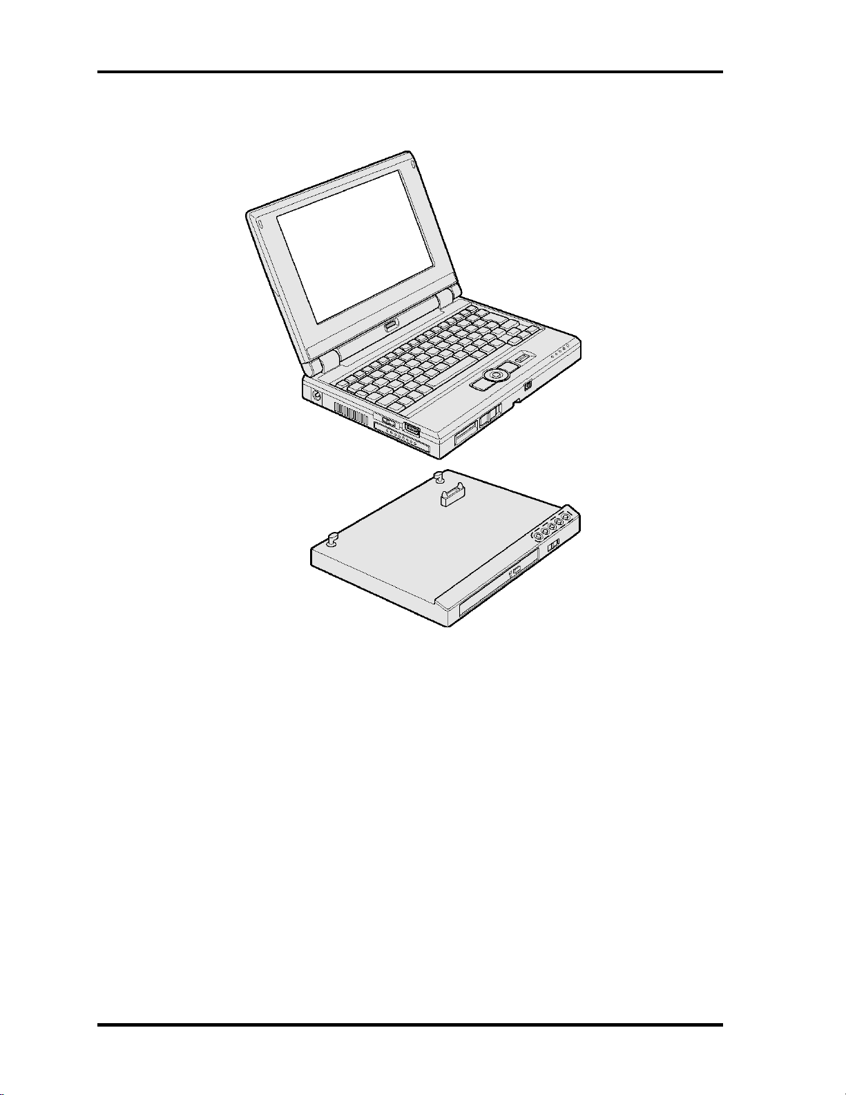
The system unit configuration is shown in Figure 1-2.
Figure 1-2 System unit configuration
libretto U100 Maintenance Manual (960-520) [CONFIDENTIAL] 1-5

1 Hardware Overview 1.1 Features
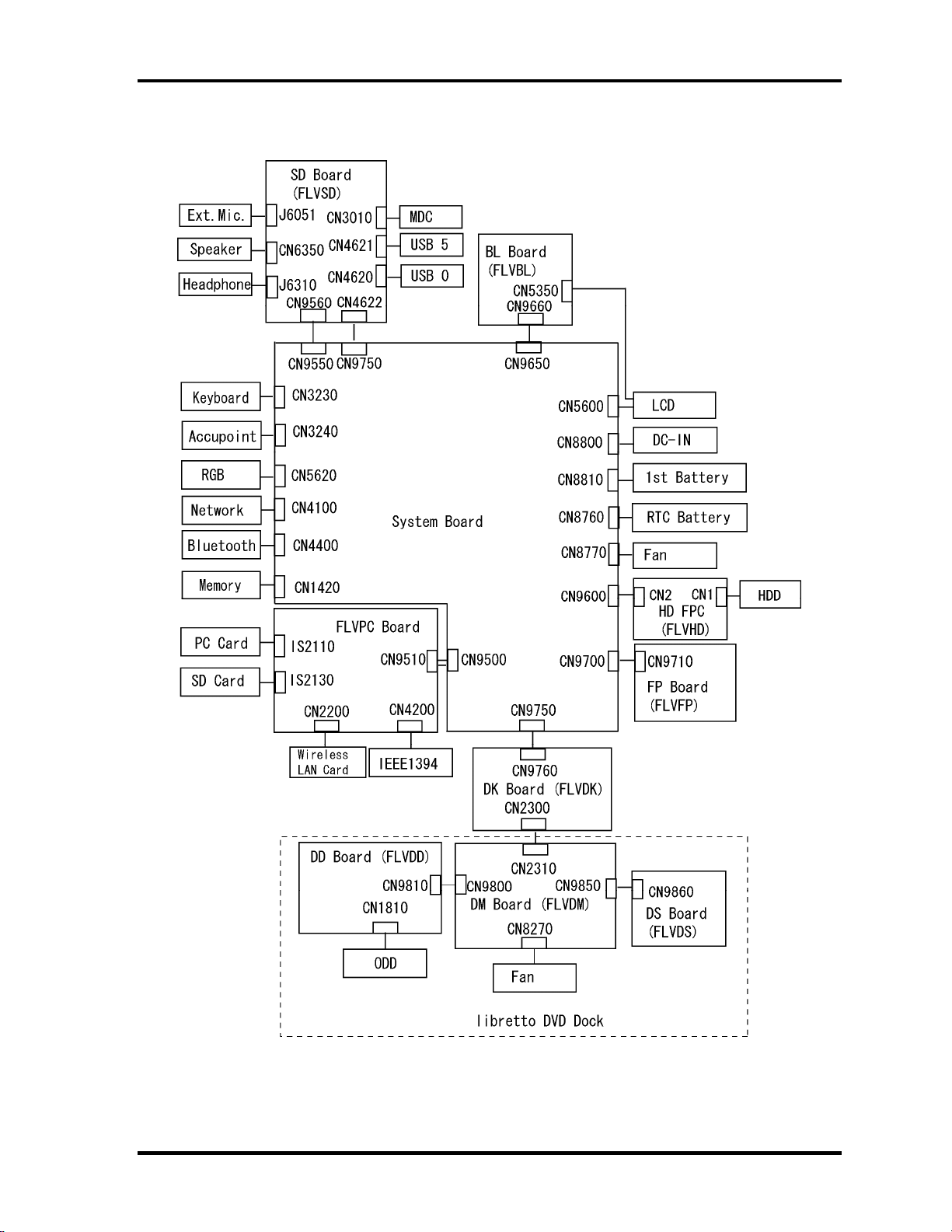
Figure 1-3 is a block diagram of the system unit.
Figure 1-3 System unit block diagram
1-6 [CONFIDENTIAL] libretto U100 Maintenance Manual (960-520)

1.1 Features 1 Hardware Overview
libretto U100 Maintenance Manual (960-520) [CONFIDENTIAL] 1-7
The system unit is composed of the following major components:
Processor
• A 1.1/1.2GHz Intel Mobile Pentium-M processor with a 400MHz external
clock, 100MHz bus and 0.94/0.81V core operation voltage (built-in NDP).
• Internal cache memory: 32KB Code and 32KB Data, Write-Back
• Secondary cache memory: 2MB (in CPU)
Memory
One DDR SO-DIMM slot is available for installation of PC2700 compatible 256, 512MB
and 1GB memory modules.
Memory
• DDR333
• 3.3V
Memory Module
• 200 pin, SO Dual In-line Memory Module (SO-DIMM)
• PC2700
• 256MB/512MB/1GB
BIOS ROM (Flash memory)
• One STMicro M50FW080NB5G is used.
• 8Mbits of flash memory are used.
PCI chipset
This gate array incorporates the following elements and functions
• North Bridge (Intel-made 855GME GMCH-M)
– Memory controller : Support DDR 266/333, MAX:2048MB
– Built-in graphics controller
– RGB, DVO Interface
– AGP V2.0 ×4 mode
– PCI R2.2
– ACPI 1.0b
– Supports Geyserville III
– Supports Intel SpeedStep technology
− 732-ball 37.5×37.5mm FC-BGA package

1 Hardware Overview 1.1 Features
1-8 [CONFIDENTIAL] libretto U100 Maintenance Manual (960-520)
• South Bridge (Intel-made ICH4-M)
– PCI 3.3V/5V Tolerance interface
– Provides Steerable PCI Interrupts for PCI device Plug-and-Play
– Enhanced DMA Controller
– Interrupt Controller
– Count/Timer
– Supports Distribute DMA
– Supports PC/PCI DMA
– Supports Serial IRQ
– LPC host controller
– Supports Plug and Play
– ACPI supporting function
– Built-in PCI IDE Controller
– USB Interface (USB2.0 ports x6)
– SMBus Interface
– Super I/O Interface
– Audio System
– SW Modem Interface
– 421-ball (31×31mm) BGA Package
VGA Controller
64MB VRAM is incorporated in North Bridge
PC card controller (Texas Instruments-made PCI7411)
•
•
•
•
•
•
•
•
PCI interface (PCI Revision2.2)
CardBus/PC Card controller (Yenta2 Version2.2) 1slot
SD/MMC card controller (SDHC Ver.1.2)
SD IO card controller (Ver.1.1)
Memory Stick/Memory Stick Pro Card Controller
xD Picture Card Controller
IEEE1394a Controller 2 port
BGA Package

1.1 Features 1 Hardware Overview
libretto U100 Maintenance Manual (960-520) [CONFIDENTIAL] 1-9
Other main system chips
•
•
•
•
•
EC/KBC (RENESAS M306KAFCLRP U0 x 1)
AXIS accelerometer (Hokuriku denki HAAM-302B)
Clock Generator (ICS 950812CGLFT)
PSC (TMP87PM48V01UG x 1)
Super I/O (SMSC LPC47N217-JV)
Sound Controller
AC97 and CODEC (STAC9750) are used.
Modem controller
Supported by MDC. Using of the secondary AC97 Line.
Internal LAN Controller (Kinnereth 82562ET)
Controls LAN (Ethernet (10BASE-T) and Fast Ethernet (100BASE-TX)) and supports
WOL. AOL is not supported.
Wireless LAN
2.4GHz DSSS/OFDM, 5.0GHz OFDM wireless LAN card is equipped. Conformity with
IEEE 802.11.
1 Hardware Overview 1.2 USB 3.5-inch Floppy Disk Drive
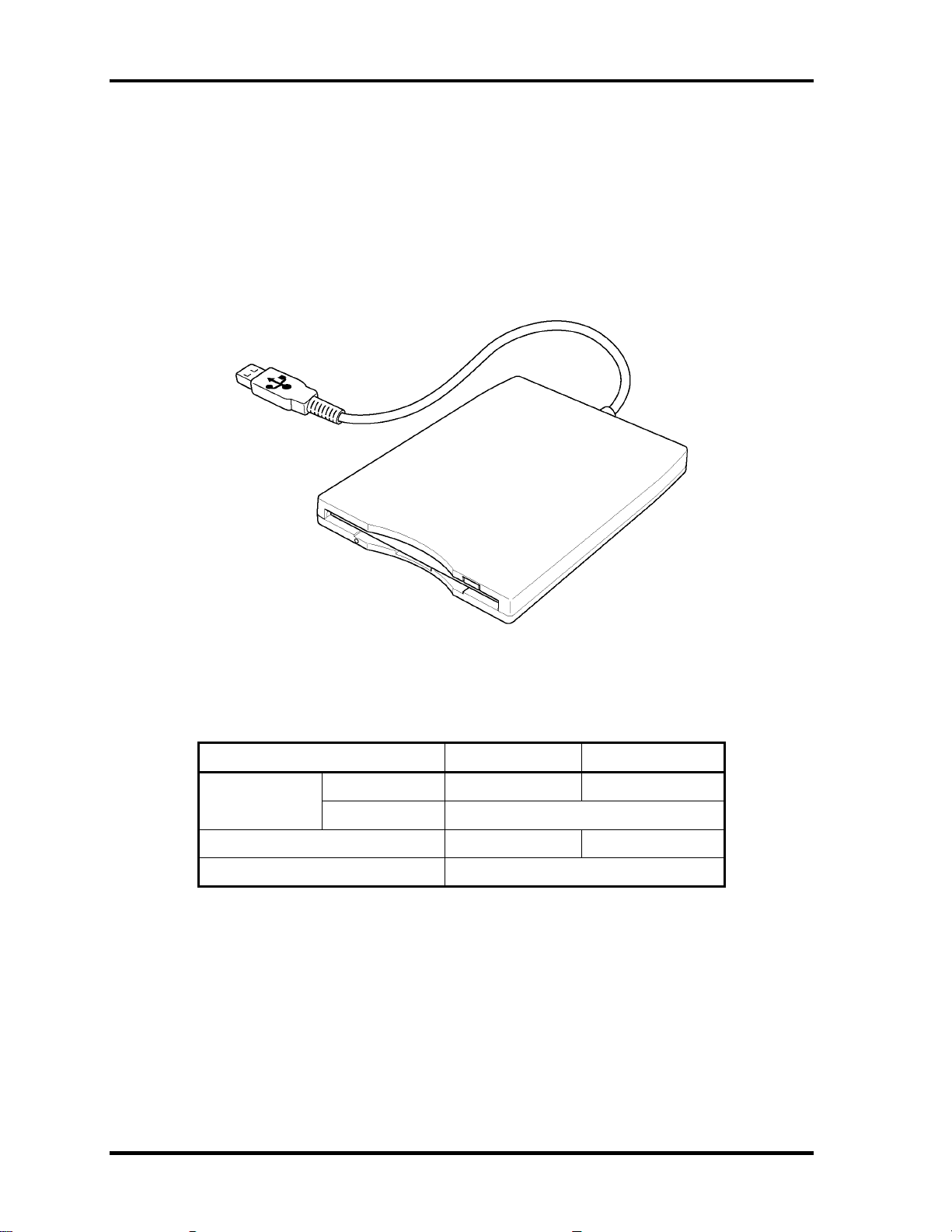
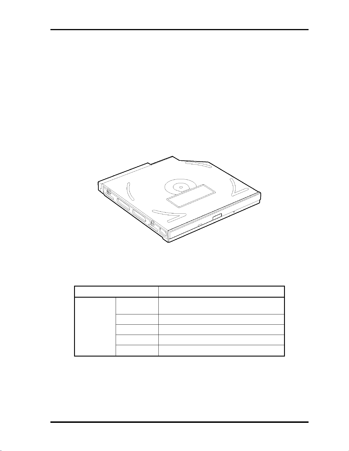
1.2 USB 3.5-inch Floppy Disk Drive
The 3.5-inch USB FDD is a thin, high-performance reliable drive that supports 720KB and
1.44MB.
The FDD is shown in figure 1-4. The specifications for the FDD are listed in Table 1-1.
Figure 1-4 USB 3.5-inch FDD
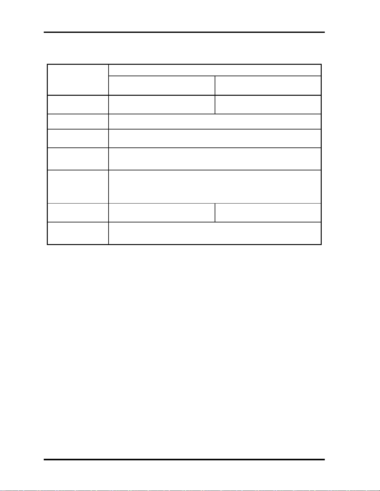
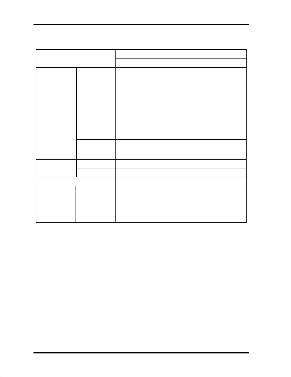
Table 1-1 USB 3.5-inch FDD specifications
Items 720KB mode 1.44MB mode
FDD part 250K bits/second 500K bits/second Data transfer
rate
USB Full speed mode (12M bits/second)
Disk rotation speed 300rpm 360rpm
Track density 5.3 track/mm (135TPI)
1-10 [CONFIDENTIAL] libretto U100 Maintenance Manual (960-520)

1.3 1.8-inch Hard Disk Drive 1 Hardware Overview
1.3 1.8-inch Hard Disk Drive
A compact, high-capacity HDD with a height of 5.0/8.0mm. Contains a 1.8-inch magnetic
disk and magnetic heads.
Figure 1-5 shows a view of the 1.8-inch HDD and Tables 1-2 and 1-3 list the dimensions and
specifications.
Figure 1-5 1.8-inch HDD
Table 1-2 1.8-inch HDD dimensions
Standard value
Parameter
TOSHIBA
HDD1442BZK01
TOSHIBA
HDD1544BZK01
Outline Width (mm)
54.0±0.2
dimensions Height (mm)
5.0±0.15 8.0±0.15
Depth (mm)
78.5±0.3
Weight (g) 51max 62max
libretto U100 Maintenance Manual (960-520) [CONFIDENTIAL] 1-11
1 Hardware Overview 1.3 1.8-inch Hard Disk Drive
1-12 [CONFIDENTIAL] libretto U100 Maintenance Manual (960-520)
Table 1-3 1.8-inch HDD specifications
Specification
Parameter
TOSHIBA
HDD1442BZK01
TOSHIBA
HDD1544BZK01
Storage size
(formatted)
30GB 60GB
Speed (RPM) 4,200
Data transfer speed
(Mbits/s)
131.1 to 283.3
Interface transfer
rate (Mbytes/s)
100(Ultra DMA mode)
16.6(PIO mode)
Track density
Track/mm(TPI)
Bit/mm(BPI)
4,704(119.5k)
31.8k(808k) max
Buffer size
(Mbytes)
2 2 or 8
Start time (sec) 3.5 typical
20 max
1.4 Optical Drive 1 Hardware Overview
1.4 Optical Drive
Optical drive is incorporated in the libretto DVD dock (option) and it is supported as a
libretto DVD dock (option).
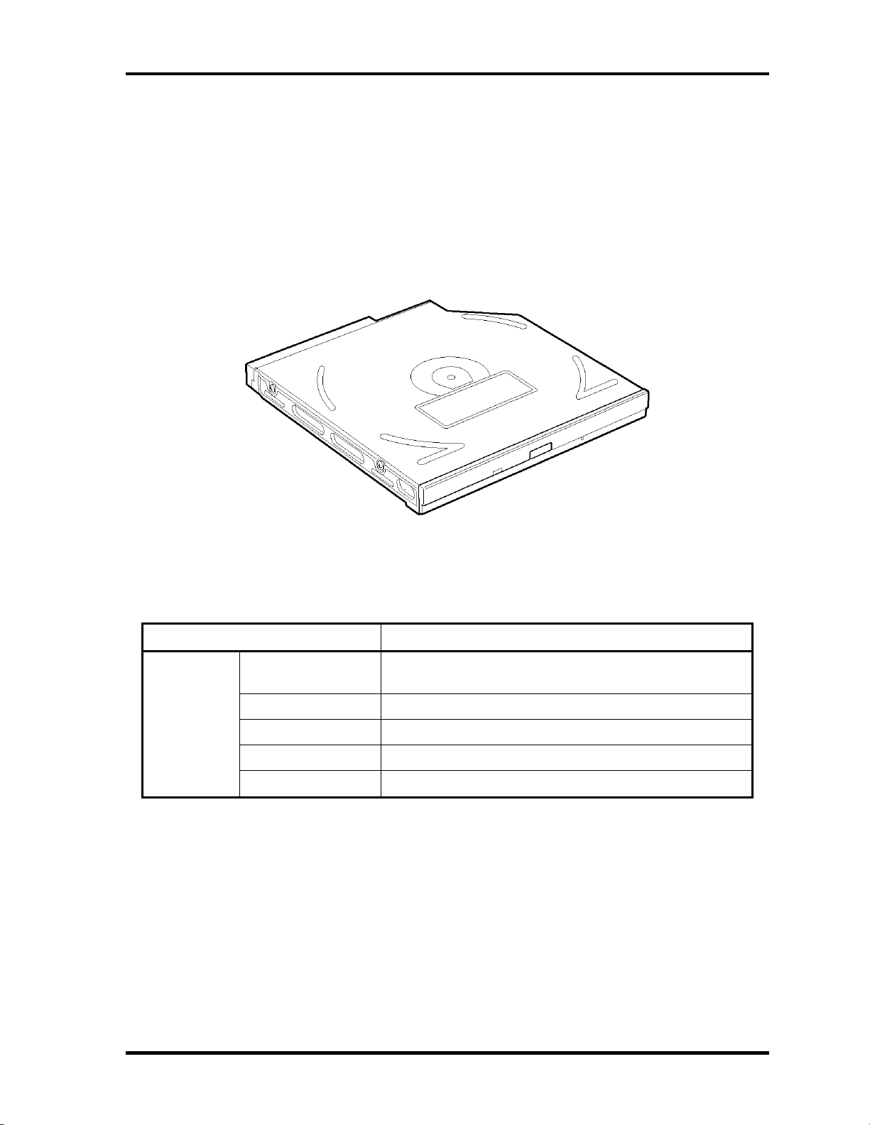
1.4.1 DVD-ROM & CD-R/RW Drive
The DVD-ROM & CD-R/RW drive accommodates either 12 cm (4.72-inch) or 8 cm (3.15-
inch) CD/DVD-ROM and CD-R/RW. It is a high-performance drive that reads DVD at
maximum 8-speed and CD at maximum 24-speed.
The DVD-ROM & CD-R/RW drive is shown in Figure 1-6. The dimensions and
specifications of the DVD-ROM & CD-R/RW drive are described in Table 1-4, Table 1-5.
Figure 1-6 DVD-ROM & CD-R/RW drive
Table 1-4 DVD-ROM & CD-R/RW drive dimensions
Parameter Standard value
Maker
MATSUSHITA
(G8CC00025110)
Width (mm) 128
Height (mm) 9.5 (excluding projections)
Depth (mm) 129.0
Outline
dimensions
Mass (g) 141±3
libretto U100 Maintenance Manual (960-520) [CONFIDENTIAL] 1-13
1 Hardware Overview 1.4 Optical Drive
1-14 [CONFIDENTIAL] libretto U100 Maintenance Manual (960-520)
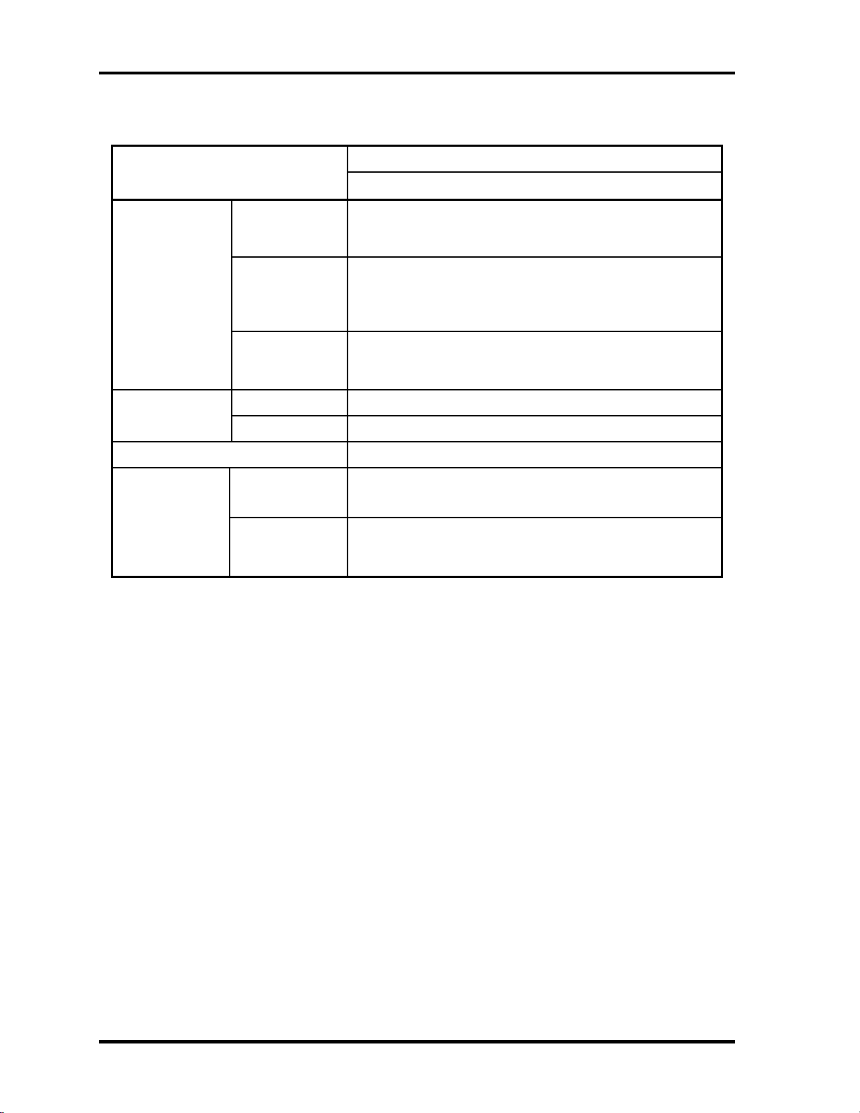
Table 1-5 DVD-ROM & CD-R/RW drive specifications
Drive Specification
Parameter
MATSUSHITA (G8CC00025110)
Read
DVD-ROM MAX 8x CAV (MAX 10800 KB/s)
CD-ROM MAX 24x CAV (MAX 3600 KB/s)
Write
CD-R 4x/8x (CLV), 16x (PCAV), MAX24x (CAV)
CD-RW 4x(CLV)
High Speed CD-RW 4x/8x/10x (CLV)
Ultra Speed CD-RW 10x (CLV), MAX24x (CAV)
Data transfer
speed
ATAPI interface
PIO mode16.6 MB/s PIO MODE4 supported
DMA mode16.6 MB/s Multi-word MODE2 supported
Ultra DMA mode 33.3 MB/s Ultra DMA MODE2
CD-ROM 150 (Random)
Access time
(ms)
DVD-ROM 170 (Random)
Buffer memory 2MB
CD
CD-DA, CD-ROM, CD-ROM XA, CD-R,CD-RW,
Photo CD, Video CD, CD-Extra(CD+), CD-text
Supported disk
format
DVD
DVD-ROM, DVD-R (DVD-R Multi-boarder supported),
DVD-RW(Ver.1.1), DVD-RAM(2.6GB/4.7GB), DVD+R,
DVD+RW
1.4 Optical Drive 1 Hardware Overview
1.4.2 DVD Super Multi Drive
The DVD Super multi drive accommodates either 12 cm (4.72-inch) or 8 cm (3.15-inch)
CD/DVD-ROM, CD-R/RW, DVD±R/±RW and DVD-RAM. It is a high-performance drive
that reads DVD-ROM at maximum 8-speed and CD at maximum 24-speed. It writes CD at
maximum 24-speed.
The DVD Super multi drive is shown in Figure 1-7. The dimensions and specifications of the
DVD Super Multi drive are described in Table 1-6, Table 1-7.
Figure 1-7 DVD Super multi drive
Table 1-6 DVD Super multi drive dimensions
Parameter Standard value
Maker
MATSUSHITA
(G8CC00026110)
Width (mm) 128
Height (mm) 9.5 (excluding projections)
Depth (mm) 129.0
Outline
dimensions
Mass (g) 145±10
libretto U100 Maintenance Manual (960-520) [CONFIDENTIAL] 1-15
1 Hardware Overview 1.4 Optical Drive
1-16 [CONFIDENTIAL] libretto U100 Maintenance Manual (960-520)
Table 1-7 DVD Super Multi drive specifications
Drive Specification
Parameter
MATSUSHITA (G8CC00026110)
Read
DVD-ROM MAX 8x CAV (MAX 10800 KB/s)
CD-ROM MAX 24x CAV (MAX 3600 KB/s)
Write
CD-R 4x/8x (CLV), 12x/16x/24x (Zone CLV)
CD-RW 4x (CLV)
High Speed CD-RW 4x/8x/10x (CLV)
Ultra Speed CD-RW 8x/10x (CLV)
DVD-R 1x/2x (CLV)
DVD-RW 1x/2x (CLV)
DVD+R 2.4x (CLV)
DVD+RW 2.4x (CLV)
DVD-RAM 2x (ZCLV) (4.7GB/9.4GB)
Data transfer
speed
ATAPI interface
PIO mode 16.6 MB/s (PIO MODE4 supported)
DMA mode 16.6 MB/s (Multi-ward MODE2 supported)
Ultra DMA mode 33.3 MB/s(Ultra DMA MODE2 supported)
CD-ROM 150 (Random)
Access time
(ms)
DVD-ROM 180 (Random)
Buffer memory 2MB
CD
CD-DA, CD-ROM, CD-R, CD-RW, CD-ROM XA,
Photo CD, Video-CD, CD-Extra(CD+),CD-text
Supported disk
format
DVD
DVD-ROM, DVD-R(3.9GB/4.7GB), DVD-RW (Ver1.1)
DVD+R/+RW, DVD Video,
DVD-RAM (2.6GB/4.7GB/9.4GB)
Loading...