


 Loading...
SENTINEL FIELD CONTROLLER
User Guide
TABLE OF CONTENTS |
|
CHAPTER 1: SENTINEL CONTROL MODULE................................... |
4 |
I. CONTROL MODULE OVERVIEW ......................................................................... |
4 |
II. USER INTERFACE OVERVIEW (KEYPAD & DISPLAY) ................................. |
5 |
Sentinel Control Module Keypad ......................................................................................................... |
5 |
Sentinel Control Module Display ......................................................................................................... |
6 |
III. PROGRAMMING OVERVIEW & NAVIGATION............................................... |
8 |
CHAPTER 2: BASIC CONTROLLER PROGRAMMING .................. |
10 |
I. CONTROLLER SETUP........................................................................................... |
10 |
UTILITY → Time & Day → Edit Mode............................................................................................ |
10 |
UTILITY → Day Change Hour → Edit Mode ................................................................................... |
12 |
UTILITY → Unit Code → Edit Mode ............................................................................................... |
12 |
UTILITY → Station Count → Edit Mode.......................................................................................... |
13 |
UTILITY → N/O Master → Edit Mode............................................................................................. |
13 |
II. SCHEDULE SETUP .............................................................................................. |
14 |
SCHEDULE DATA → Run Days → Edit Mode............................................................................... |
14 |
III. PROGRAM SETUP .............................................................................................. |
15 |
PROGRAM DATA → Start Times → Edit Mode ............................................................................. |
15 |
PROGRAM DATA → Slot-Stn-Time → Edit Mode ......................................................................... |
16 |
PROGRAM DATA → Percent Scale → Edit Mode .......................................................................... |
18 |
PROGRAM DATA → Repeats → Edit Mode ................................................................................... |
18 |
PROGRAM DATA → Repeat Dly Time → Edit Mode..................................................................... |
18 |
PROGRAM DATA → Continuous Run → Edit Mode...................................................................... |
19 |
PROGRAM DATA → Water Window → Edit Mode........................................................................ |
19 |
PROGRAM DATA → Selected Schedule → Edit Mode................................................................... |
19 |
CHAPTER 3: ADVANCED PROGRAMMING..................................... |
22 |
I. OPERATIONS MENU............................................................................................. |
22 |
Manual (Manual Station) .................................................................................................................... |
22 |
Auto Slot/Stn (Manual Program Start)................................................................................................ |
22 |
Rain Off Days ..................................................................................................................................... |
23 |
All Manuals Off (Manual Stations Off) .............................................................................................. |
23 |
All Autos Off (Manual / Auto Programs Off)..................................................................................... |
23 |
Stn Days Off ....................................................................................................................................... |
23 |
II. UTILITY MENU..................................................................................................... |
23 |
Program Clear ..................................................................................................................................... |
23 |
Wireless Group ................................................................................................................................... |
24 |
Map Unit Precode ............................................................................................................................... |
24 |
Two-Wire / Irritrol Mode.................................................................................................................... |
24 |
III. FLOW MENU ....................................................................................................... |
24 |
K Factor .............................................................................................................................................. |
24 |
Offset Factor ....................................................................................................................................... |
24 |
Current Flow ....................................................................................................................................... |
25 |
Expected Flows................................................................................................................................... |
25 |
Maximum Flows ................................................................................................................................. |
25 |
Flow Processing.................................................................................................................................. |
25 |
Read Flow Totals ................................................................................................................................ |
25 |
2
IV. ALARMS MENU ................................................................................................... |
26 |
Master Minimum ................................................................................................................................ |
26 |
Unexpected Flow ................................................................................................................................ |
26 |
Over Flows.......................................................................................................................................... |
26 |
Over Currents...................................................................................................................................... |
27 |
Clear Flow Alarms.............................................................................................................................. |
27 |
Clear Fuse Alarms............................................................................................................................... |
27 |
Clear Map Alarms............................................................................................................................... |
27 |
Clear Power Fail ................................................................................................................................. |
27 |
V. ZONE / ET DATA MENU ...................................................................................... |
28 |
Plant Factor:........................................................................................................................................ |
28 |
Application Rate: ................................................................................................................................ |
28 |
Default ET........................................................................................................................................... |
28 |
Maximum ET...................................................................................................................................... |
28 |
Program ET Toggle............................................................................................................................. |
29 |
Station Type........................................................................................................................................ |
29 |
Map Stations ....................................................................................................................................... |
29 |
3

CHAPTER 1: SENTINEL CONTROL MODULE
I. CONTROL MODULE OVERVIEW
Your Sentinel Controller Interface has three main elements to use throughout the programming process. These are:
Program Instructions |
Display |
Keypad |
Card |
|
|
The display, keypad and program instructions card are located on the front panel of the satellite control module. Programming as covered in this User’s Guide will be through the keypad and display (not through the central software). The Program Instructions card is provided as a quick-reference of Main Menu and Submenu elements for controller programming.
4
Other visible elements of the satellite control module include the radio antenna connector, the station output ports (up to four 15-pin connectors), and the red “power on” light, all located on the bottom front side of the control module.
The back side panel of the control module is where the serial port (9-pin connector), data retrieval port (9-pin connector) and two fuse sockets are located. A red LED light is provided next to the fuse socket to indicate a blown fuse.
Sentinel satellite controllers are available in various station output configurations in 12station increments, including 12-, 24-, 36-, and 48-stations.
II. USER INTERFACE OVERVIEW (KEYPAD & DISPLAY)
Sentinel Control Module Keypad
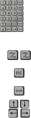
The Sentinel Control Module has a 24-button keypad for use as the programming interface:
This keypad includes numeric buttons 1 – 9 and 0 used for numeric data entry. Also used in programming and operations are:
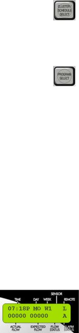
ON/YES & OFF/NO Keys |
|
Used for manual operations |
|
|
as well as entering ON / |
|
|
OFF or YES / NO in |
|
|
programming. |
ESC (Escape) Key |
|
Used for exiting menus or |
|
|
Edit Mode and returning to |
|
|
normal operations (default |
|
|
screen) |
ENTER Key |
|
Used for functions like |
|
|
entering a selected submenu |
|
|
or saving information. |
Arrow (Navigation) Keys |
|
Used for navigating in |
|
|
Menus, Submenus, and Edit |
|
|
Modes, as well an |
|
|
incrementing values in |
|
|
programming. |
5
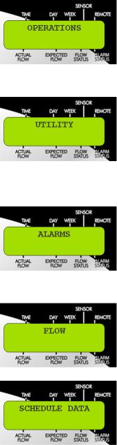
CLUSTER / SCHEDULE |
|
This button will be |
SELECT Key |
|
described in more detail in |
|
|
later parts of this guide. |
|
|
Used for selecting Clusters |
|
|
(groups of 4 programs) or |
|
|
schedules (run days) when |
|
|
programming. |
PROGRAM SELECT Key |
|
This button will be |
|
|
described in more detail in |
|
|
later pars of this guide. |
|
|
Used for selecting the |
|
|
Program (1-4) associated |
|
|
with a Clusters when |
|
|
programming. |
Also included are four F-keys provided on the control module keypad to conveniently perform the following functions:
F1 Key  - Displays the time.
F2 Key  - Displays the status of the automatic programs.
F3 Key  - Shuts down anything that is running (panic button).
IMPORTANT: The F3 key is not functional while in the Edit mode. F4 Key  - Displays context sensitive help while in the Edit mode.
Sentinel Control Module Display
The Sentinel Controller has a two-line LCD for display of information. When you first walk up to your Sentinel controller, the display should be in its standard mode showing current time, day, week (of schedule), actual flow (if anything running) and expected flow. This display should look something like the following:
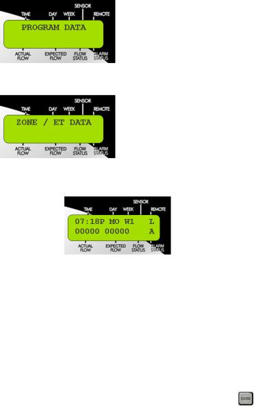
This display (as shown) indicates:
Upper Line |
Lower Line |
Time – 07:18 P (7:18 PM) |
Actual Flow – 00000 (0 GPM) |
Day – MO (Monday) |
Expected Flow – 00000 (0 GPM) |
Week (of schedule) – W1 (Week 1) |
Flow Status – No current flow indicator |
Sensor – No current sensor indication |
Alarm Status – A (Alarm Exists) |
Remote – L (Locked) |
|
6
The standard indicators in the display are as follows:
TIME |
HH:MM |
Hours : Minutes (12-hour format) |
|
A |
AM |
|
P |
PM |
DAY |
SU |
Sunday |
|
MO |
Monday |
|
TU |
Tuesday |
|
WE |
Wednesday |
|
TH |
Thursday |
|
FR |
Friday |
|
SA |
Saturday |
WEEK |
W1 |
Week 1 (one) of Schedule |
|
W2 |
Week 2 (two) of Schedule |
|
W3 |
Week 3 (three) of Schedule |
|
W4 |
Week 4 (four) of Schedule |
|
W5 |
Week 5 (five) of Schedule |
|
W6 |
Week 6 (six) of Schedule |
SENSOR |
1 |
Sensor Activated - Switch sensor is in |
|
|
alternate of its Normal condition. E.g. If |
|
|
Normally Open, then 1 = Sensor |
|
|
Closed. |
|
O |
Dry contact (switch) sensor is Open |
|
C |
Dry contact (switch) sensor is Closed |
REMOTE |
L |
Field Unit is in remote “Locked” mode. |
|
|
Hand held radio will not activate |
|
|
watering functions within this unit. |
|
A |
Field Unit is programmed for “All |
|
|
Call” handheld radio operation. |
|
|
Controller will respond to any and all |
|
|
handheld commands transmitted. |
|
S |
Field Unit is programmed for “Secure” |
|
|
handheld radio operation. Controller |
|
|
will respond only to handheld |
|
|
commands addressed to its unit code. |
ACTUAL |
00000 |
5-digit numeric indicator of current |
FLOW |
|
flow through connected flow sensor |
EXPECTED |
00000 |
5-digit numeric indicator of expected |
FLOW |
|
flow based on current stations operating |
|
|
and their expected flows. |
FLOW |
+ |
Actual > Expected (Overflow) |
STATUS |
|
|
|
-- |
Actual < Expected (Underflow) |
|
:) |
Actual = Expected (Flow is happy) |
|
A |
Flow Alarm Exists |
ALARM |
A |
Alarm Exists – Blank Otherwise |
STATUS |
|
|
7
III. PROGRAMMING OVERVIEW & NAVIGATION
The Sentinel Controller is programmed by navigating through a Main Menu which includes seven options: Operations, Utility, Alarms, Flow, Schedule Data, Program Data, and Zone/ET Data. Each of these Main Menu options has a Submenu for entering and changing data. This structure is detailed below as well as being shown on the Program Instructions Card on the control module itself.
MENU |
SUBMENU |
|
|
• |
Manual |
|
• Auto Slot / Station |
|
|
• |
Rain Off Days |
|
• |
All Manuals Off |
|
• |
All Autos Off |
|
• |
Station Days Off |
|
• |
Time & Day |
|
• |
Day Change Hour |
|
• |
Unit Code |
|
• |
Station Count |
|
• |
Program Clear |
|
• |
N/O Master |
|
• |
Wireless Group |
|
• |
Map Unit Precode |
|
• Two-Wire / Irritrol Mode |
|
|
• |
Master Minimum |
|
• |
Unexpected Flow |
|
• |
Over Flows |
|
• |
Over Currents |
|
• |
Clear Flow Alarms |
|
• |
Clear Fuse Alarms |
|
• |
Clear Map Alarms |
|
• |
Clear Power Fail |
|
• |
K Factor |
|
• |
Offset Factor |
|
• |
Current Flow |
|
• |
Expected Flows |
|
• |
Maximum Flows |
|
• |
Flow Processing |
|
• |
Read Flow Totals |
|
• |
Run Days |
|
|
|
8
|
• |
Start Times |
|
• |
Slot-Station-Time |
|
• |
Percent Scale |
|
• |
Repeats |
|
• |
Repeat Delay time |
|
• |
Continuous Run |
|
• |
Water Window |
|
• |
Assigned Schedule |
|
• |
Plant Factor |
|
• |
Application Rate |
|
• |
Default ET |
|
• |
Maximum ET |
|
• |
Program ET Toggle |
|
• |
Station Type |
|
• |
Map Stations |
The controller normal mode (default) screen looks like:
•To enter the Main Menu from this default screen, you need to hit any of the arrow
keys on the keypad:  ,
,  ,
,  , or
, or  . This will bring up the OPERATIONS option of the Main menu.
•To navigate through the Main Menu, use the right or left arrow keys:  or
or  .
.
•To enter a submenu for any of the Main menu options, use the up or down arrow keys:  or
or  .
.
• When the desired submenu is reached, press the enter key |
to view or change data |
in the submenu. |
|
IMPORTANT: When entering data into one of the submenus, the controller is in the Edit Mode. The controller will not begin any scheduled operation until you have exited the Edit Mode. Programs that are running prior to entering the Edit Mode will continue running. Any time you enter or change any data, you must press the
ENTER  key to save the data. Otherwise, the newly entered data will not be saved.
To exit the Edit Mode, press the ESC  Escape) key once or twice as necessary to return to normal mode (default) screen. If you forget to press the ESC key, the controller will automatically revert to normal mode after two minutes.
9
Loading...