


 Loading...
Form No. 3417-438 Rev A
TimeCutter® HD MyRide 48in, 54in, or 60in Riding Mower
Model No. 75211—Serial No. 402000000 and Up
Model No. 75212—Serial No. 402000000 and Up
Model No. 75213—Serial No. 402000000 and Up
Register at www.Toro.com. |
*3417-438* A |
Original Instructions (EN) |

 WARNING
CALIFORNIA
Proposition 65 Warning
This product contains a chemical or chemicals known to the State of California to cause cancer, birth defects, or reproductive harm.
The engine exhaust from this product contains chemicals known to the State of California to cause cancer, birth defects, or other reproductive harm.
It is a violation of California Public Resource Code Section 4442 or 4443 to use or operate the engine on any forest-covered, brush-covered, or grass-covered land unless the engine is equipped with a spark arrester, as defined in Section 4442, maintained in effective working order or the engine is constructed, equipped, and maintained for the prevention of fire.
Gross or Net Torque
The gross or net torque of this engine was laboratory rated by the engine manufacturer in accordance with the Society of Automotive Engineers (SAE) J1940 or J2723. As configured to meet safety, emission, and operating requirements, the actual engine torque on this class of mower will be significantly lower.
Go to www.Toro.com to view specifications on your mower model.

 WARNING
Removing standard original equipment parts and accessories may alter the warranty, traction, and safety of the machine. Failure to use original Toro parts could cause serious injury or death. Making unauthorized changes to the engine, fuel or venting system, may violate EPA and CARB regulations.
Replace all parts including, but not limited to, tires, belts, blades, and fuel system components with original Toro parts.
Important: If you are using a machine with a Toro engine above 1500 m (5,000 ft) for a continuous period, ensure that the High Altitude Kit has been installed so that the engine meets CARB/EPA emission regulations. The High Altitude Kit increases engine performance while preventing spark-plug fouling, hard starting, and increased emissions. Once you have installed the kit, attach the high-altitude label next to the serial decal on the machine. Contact any Authorized Toro Service Dealer to obtain the proper High Altitude Kit and
high-altitude label for your machine. To locate a dealer convenient to you, access our website at www.Toro.com or contact our Toro Customer Care Department at the number(s) listed in your Emission Control Warranty Statement.
Remove the kit from the engine and restore the engine to its original factory configuration when running the engine under 1500 m (5,000 ft). Do not operate an engine that has been converted for high-altitude use at lower altitudes; otherwise, you could overheat and damage the engine.
If you are unsure whether or not your machine has been converted for high-altitude use, look for the following label.
decal127-9363
Introduction
This rotary-blade, riding lawn mower is intended to be used by homeowners in residential applications. It is designed primarily for cutting grass on well-maintained lawns. It is not designed for cutting brush, mowing grass and other growth alongside highways, or for agricultural uses.
Read this information carefully to learn how to operate and maintain your product properly and to avoid injury and product damage. You are responsible for operating the product properly and safely.
You may contact Toro directly at www.Toro.com for product safety and operation training materials, accessory information, help finding a dealer, or to register your product.
Whenever you need service, genuine Toro parts, or additional information, contact an Authorized Service Dealer or Toro Customer Service and have the model and serial numbers of your product ready. Figure 1 identifies the location of the model and serial numbers on the product. Write the numbers in the space provided.
Important: With your mobile device, you can scan the QR code on the serial number decal (if equipped) to access warranty, parts, and other product information.
© 2017—The Toro® Company |
|
Contact us at www.Toro.com. |
|
8111 Lyndale Avenue South |
|
Printed in the USA |
|
2 |
|||
Bloomington, MN 55420 |
All Rights Reserved |

g234368
Figure 1
1.Model and serial number plate
Write the product model and serial numbers in the space below:
Model No.
Serial No.
This manual identifies potential hazards and has safety messages identified by the safety-alert symbol (Figure 2), which signals a hazard that may cause serious injury or death if you do not follow the recommended precautions.
g000502
Figure 2
Safety-Alert Symbol
This manual uses 2 words to highlight information. Important calls attention to special mechanical information and Note emphasizes general information worthy of special attention.
Contents |
|
Safety ....................................................................... |
4 |
General Safety ................................................... |
4 |
Slope Indicator ................................................... |
5 |
Safety and Instructional Decals .......................... |
6 |
Product Overview .................................................... |
11 |
Controls ............................................................ |
11 |
Before Operation ................................................. |
13 |
Before Operation Safety ................................... |
13 |
Adding Fuel ...................................................... |
13 |
Performing Daily Maintenance.......................... |
14 |
Breaking in a New Machine .............................. |
14 |
Using the Safety-Interlock System.................... |
15 |
Positioning the Seat.......................................... |
16 |
Adjusting the MyRide™ Suspension |
|
System.......................................................... |
16 |
Adjusting the Motion-Control Levers ................. |
17 |
During Operation ................................................. |
18 |
During Operation Safety ................................... |
18 |
Entering the Operator’s Position ....................... |
20 |
Operating the Parking Brake............................. |
20 |
Operating the Mower Blade-Control Switch |
|
(PTO)............................................................ |
20 |
Operating the Throttle....................................... |
21 |
Operating the Choke......................................... |
21 |
Starting the Engine ........................................... |
22 |
Shutting Off the Engine..................................... |
22 |
Using the Motion-Control Levers....................... |
22 |
Driving the Machine.......................................... |
23 |
Using the Smart SpeedTM Control |
|
System.......................................................... |
24 |
Using the Side Discharge ................................. |
25 |
Adjusting the Height of Cut ............................... |
26 |
Adjusting the Anti-Scalp Rollers........................ |
27 |
Using Attachments and Accessories................. |
27 |
Operating Tips ................................................. |
27 |
After Operation .................................................... |
28 |
After Operation Safety ...................................... |
28 |
Pushing the Machine by Hand .......................... |
28 |
Transporting the Machine ................................. |
29 |
Maintenance ........................................................... |
31 |
Recommended Maintenance Schedule(s) ........... |
31 |
Pre-Maintenance Procedures .............................. |
32 |
Maintenance Safety.......................................... |
32 |
Engine Maintenance ........................................... |
32 |
Engine Safety ................................................... |
32 |
Servicing the Air Cleaner .................................. |
32 |
Servicing the Engine Oil.................................... |
34 |
Servicing the Spark Plug................................... |
36 |
Cleaning the Cooling System............................ |
37 |
Fuel System Maintenance ................................... |
38 |
Replacing the In-Line Fuel Filter ....................... |
38 |
Electrical System Maintenance ........................... |
39 |
Electrical System Safety................................... |
39 |
Servicing the Battery......................................... |
39 |
Servicing the Fuses .......................................... |
40 |
Drive System Maintenance .................................. |
41 |
3

Checking the Tire Pressure............................... |
41 |
Mower Maintenance............................................. |
41 |
Servicing the Cutting Blades............................. |
41 |
Leveling the Mower Deck.................................. |
44 |
Removing the Mower Deck............................... |
46 |
Installing the Mower Deck................................. |
47 |
Replacing the Grass Deflector .......................... |
47 |
Mower Belt Maintenance...................................... |
48 |
Inspecting the Belts .......................................... |
48 |
Replacing the Mower Belt................................. |
48 |
Cleaning .............................................................. |
49 |
Washing the Underside of the Mower................ |
49 |
Cleaning the Suspension System ..................... |
50 |
Disposing of Waste........................................... |
50 |
Storage ................................................................... |
50 |
Storage Safety.................................................. |
50 |
Cleaning and Storage....................................... |
50 |
Storing the Battery............................................ |
51 |
Troubleshooting ...................................................... |
52 |
Schematics ............................................................. |
54 |
Safety
This machine has been designed in accordance with ANSI B71.1-2012.
General Safety
This product is capable of amputating hands and feet and of throwing objects. Always follow all safety instructions to avoid serious personal injury.
Using this product for purposes other than its intended use could prove dangerous to you and bystanders.
•Do not operate the machine near drop-offs, ditches, embankments, water, or other hazards, or on slopes greater than 15 degrees.
•Read and understand the contents of this Operator’s Manual before starting the engine.
•Do not put your hands or feet near moving components of the machine.
•Do not operate the machine without all guards and other safety protective devices in place and working on the machine.
•Keep children and bystanders out of the operating area. Never allow children to operate the machine.
•Stop the machine and shut off the engine before servicing, fueling, or unclogging the machine.
Improperly using or maintaining this machine can result in injury. To reduce the potential for injury, comply with these safety instructions and always pay attention to the safety-alert symbol, which means Caution, Warning, or Danger—personal safety instruction. Failure to comply with these instructions may result in personal injury or death.
You can find additional safety information where needed throughout this manual.
4
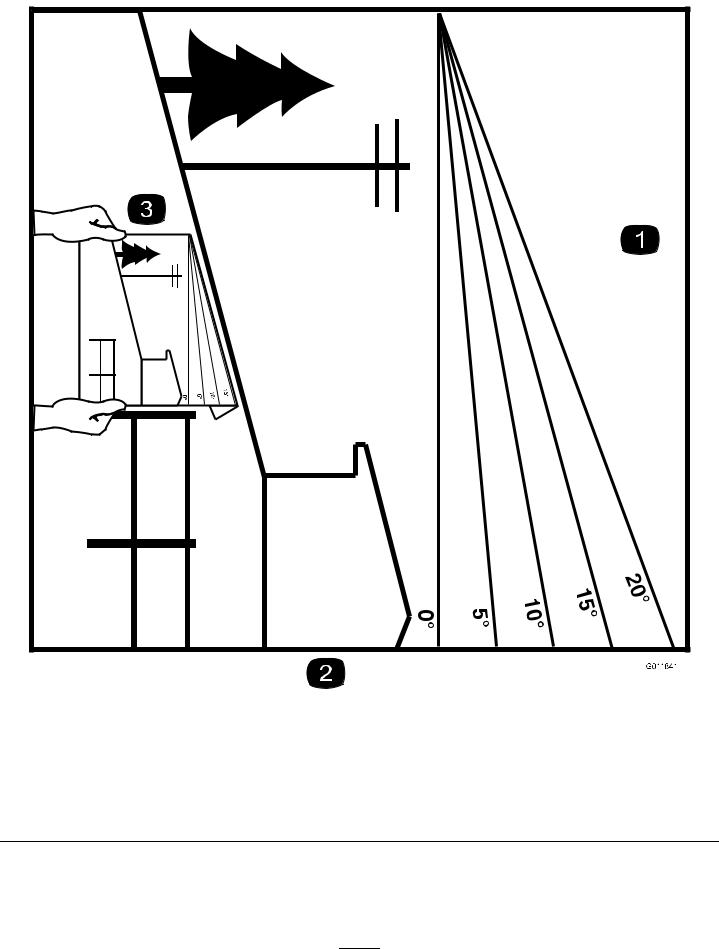
Slope Indicator
g011841
Figure 4
This page may be copied for personal use.
1.The maximum slope you can operate the machine on is 15 degrees. Use the slope chart to determine the degree of slope of hills before operating. Do not operate this machine on a slope greater than 15 degrees. Fold along the appropriate line to match the recommended slope.
2.Align this edge with a vertical surface, a tree, building, fence pole, etc.
3.Example of how to compare slope with folded edge
5
Safety and Instructional Decals
Safety decals and instructions are easily visible to the operator and are located near any area of potential danger. Replace any decal that is damaged or missing.
decaloemmarkt
Manufacturer's Mark
1. Indicates the blade is identified as a part from the original machine manufacturer.
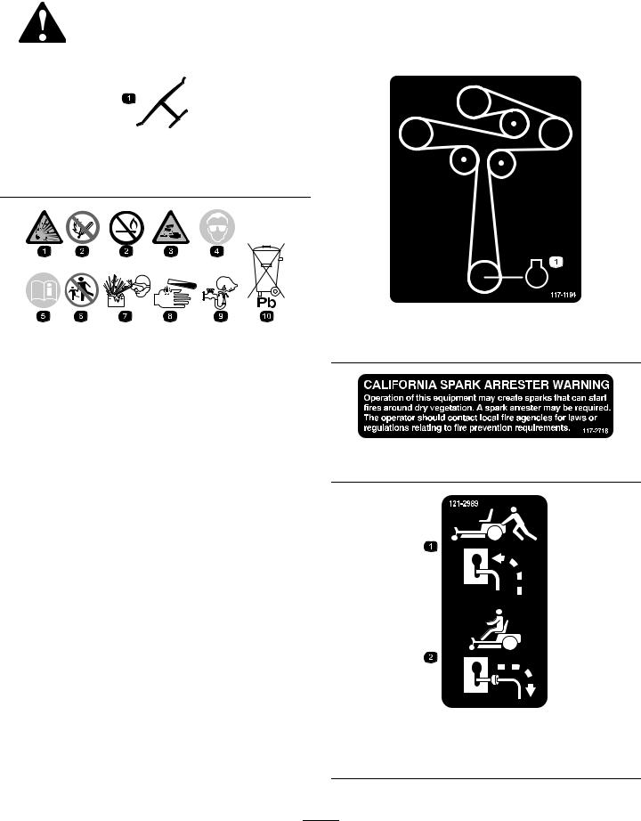
decal117-1194
117-1194
Battery Symbols |
decalbatterysymbols |
1. Engine |
Some or all of these symbols are on your battery.
1. Explosion hazard |
6. Keep bystanders a safe |
|
distance away from the |
|
battery. |
2.No fire, open flame, or smoking
7. Wear eye protection; |
|
explosive gases can |
|
cause blindness and other |
decal117-2718 |
injuries. |
117-2718 |
3. |
Caustic liquid/chemical |
8. |
Battery acid can cause |
|
burn hazard |
|
blindness or severe burns. |
4. |
Wear eye protection. |
9. |
Flush eyes immediately |
|
|
|
with water and get medical |
|
|
|
help fast. |
5. |
Read the Operator's |
10. |
Contains lead; do not |
|
Manual. |
|
discard |
|
|
|
|
decal121-2989b
121-2989
1.Bypass lever position for pushing the machine
2.Bypass lever position for operating the machine
6
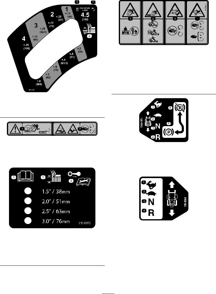
decal130-0654
130-0654
1. Transport—lock |
3. Height of cut |
2. Transport—unlock
130-0731 |
decal130-0731 |
|
|
||
1. Warning—thrown object |
2. |
Cutting hazard of hand or |
hazard; keep the deflector |
|
foot, mower blade—keep |
shield in place. |
|
away from moving parts. |
|
|
|
decal130-0765
130-0765
1.Read the Operator's 3. Remove the key from the
Manual. |
key switch and read the |
|
Operator's Manual before |
|
performing maintenance. |
2.Height-of-cut selection
decal132-0872
132-0872
1.Thrown object hazard—keep bystanders away from the machine.
2.Thrown object hazard, raised baffle—do not operate the machine with an open deck; use a bagger or a baffle.
3.Severing hazard of hand or foot—keep away from moving parts.
4.Entanglement hazard—keep away from moving parts; keep all guards and shields in place.
|
|
136-4243 |
decal136-4243 |
|
|
|
|
1. |
Fast |
4. |
Reverse |
2. |
Slow |
5. |
Parking brake disengaged |
3. |
Neutral |
6. |
Parking brake engaged |
|
|
|
|
decal136-4244
|
|
136-4244 |
|
1. |
Fast |
3. |
Neutral |
2. |
Slow |
4. |
Reverse |
|
|
|
|
7

decal136-4245
|
|
136-4245 |
1. |
Slow |
3. Fast |
2. |
Transport |
|
|
|
|
decal136-5596
136-5596
1.Check the tire pressure every 25 operating hours.
2.Engine oil
4.Check the tire pressure every 25 operating hours.
5.Read the Operator's Manual before performing maintenance.
3.Check the tire pressure every 25 operating hours.
decal136-9186
136-9186
1.Read the Operator's Manual before adding weight to the bucket.
8
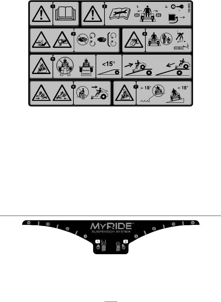
decal132-0869
132-0869
Note: This machine complies with the industry standard stability test in the static lateral and longitudinal tests with the maximum recommended slope indicated on the decal. Review the instructions for operating the machine on slopes in the Operator’s Manual as well as the conditions in which you would operate the machine to determine whether you can operate the machine in those conditions on that day and at that site. Changes in the terrain can result in a change in slope operation for the machine. If possible, keep the cutting units lowered to the ground while operating the machine on slopes. Raising the cutting units while operating on slopes can cause the machine to become unstable.
1.Warning—read the
Operator's Manual.
2.Warning—before servicing, engage the parking brake, remove the key and the spark plug connection.
3.Cutting hazard of hand, mower blade; pinching hazard of hand, belt—keep hands and feet away from moving parts; keep all guards and shields in place.
4.Thrown object hazard—keep bystanders away from the machine; remove debris from the area before mowing; keep the deflector shield down.
5.Ramp tipping hazard—when loading onto a trailer, do not use dual ramps; use only a single ramp wide enough for the machine and that has an incline less than 15 degrees; back up the ramp (in reverse) and drive forward off the ramp.
6.Bodily harm hazard—no riders; look behind you when mowing in reverse.
7.Tipping hazard on slopes—do not use on slopes near open water; do not use on slopes greater than 15 degrees.
decal133-5198
133-5198
1. Cam lock |
2. Cam unlock |
|
|
9
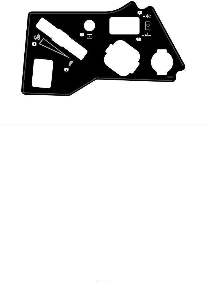
decal133-9263
|
|
133-9263 |
|
1. |
Fast |
4. |
PTO disengage |
2. |
Slow |
5. |
PTO engage |
3.Choke
10
Product Overview |
Controls |
|
Become familiar with all controls in Figure 6 and |
|
Figure 7 before you start the engine and operate the |
|
machine. |
|
Control Panel |
Figure 5
1. |
Deck-lift pedal |
7. |
Engine |
2. |
Height-of-cut pin |
8. |
Fuel cap |
3. |
Height-of-cut |
9. |
Mower deck |
|
lever/transport lock |
|
|
4. |
Smart Speed™ lever |
10. |
Anti-scalp roller |
5. |
Motion-control lever |
11. |
Caster wheel |
6. |
Controls |
12. |
Parking-brake lever |
g188738
|
|
|
Figure 6 |
|
1. |
Hour meter |
4. |
Key switch |
|
g195717 |
Throttle control |
5. |
Blade-control switch |
|
2. |
||||
|
|
|
|
(power takeoff) |
3. |
Choke control |
6. |
12 V power point |
|
|
|
|
|
|
Fuel Gauge
The fuel gauge displays the amount of fuel in the tank (Figure 7).
g188776
Figure 7
1.Fuel gauge
Throttle Control
The throttle controls the engine speed, and it has a continuous-variable setting from the SLOW to FAST position (Figure 6).
11

Choke Control
Use the choke control to start a cold engine.
Hour Meter
The hour meter records the number of hours the engine has operated. It operates when the engine is running. Use these times for scheduling regular maintenance (Figure 6).
Motion-Control Levers
Use the motion-control levers to drive the machine forward, reverse, and turn either direction (Figure 5).
Neutral-Lock Position
Move the motion-control levers outward from the center to the NEUTRAL-LOCK position when exiting the machine (Figure 24). Always position the motion-control levers into the NEUTRAL-LOCK position when you stop the machine or leave it unattended.
Parking-Brake Lever
The parking-brake lever is located on left side of the console (Figure 5). The brake lever engages a parking brake on the drive wheels.
To engage the parking brake, pull up the lever until it latches into the detent slot.
To disengage the parking brake, pull the lever out of the detent slot and toward you, then push it down.
Foot Pedal Deck-Lift System
The foot pedal deck-lift system allows you to lower and raise the deck from the seated position. You can use the foot pedal to lift the deck briefly to avoid obstacles or lock the deck in the highest height of cut or transport position (Figure 5).
Smart Speed™ Control System
Lever
The Smart Speed™ Control-System lever, located below the operating position, gives you a choice to drive the machine at 3 speed ranges— trim, tow, and mow (Figure 5).
12 V Power Point
Use the power point to power 12 V accessories (Figure 6).
Important: When not using the 12 V power point, insert the rubber plug to prevent damage to the power point.
Key Switch
The key switch, used to start and shut off the engine, has 3 positions: OFF, RUN, and START. Refer to Starting the Engine (page 22).
Blade-Control Switch (Power
Takeoff)
The blade-control switch, represented by a power-takeoff (PTO) symbol, engages and disengages power to the mower blades (Figure 6).
Height-of-Cut Lever
The height-of-cut lever works with the foot pedal to lock the deck in a specific cutting height. Adjust the height of cut only when the machine is not moving (Figure 5).
Attachments/Accessories
A selection of Toro approved attachments and accessories is available for use with the machine to enhance and expand its capabilities. Contact your Authorized Service Dealer or Distributor or go to www.Toro.com for a list of all approved attachments and accessories.
To best protect your investment and maintain optimal performance of your Toro equipment, count on Toro genuine parts. When it comes to reliability, Toro delivers replacement parts designed to the exact engineering specification of our equipment. For peace of mind, insist on Toro genuine parts.
12

Operation
Note: Determine the left and right sides of the machine from the normal operating position.
Before Operation
Before Operation Safety
General Safety
•Never allow children or untrained people to operate or service the machine. Local regulations may restrict the age of the operator. The owner is responsible for training all operators and mechanics.
•Become familiar with the safe operation of the equipment, operator controls, and safety signs.
•Know how to stop the machine and shut off the engine quickly.
•Check that operator-presence controls, safety switches, and shields are attached and functioning properly. Do not operate the machine unless they are functioning properly.
•Before mowing, always inspect the machine to ensure that the blades, blade bolts, and cutting assemblies are in good working condition.
Replace worn or damaged blades and bolts in sets to preserve balance.
•Inspect the area where you will use the machine and remove all objects that the machine could throw.
•Evaluate the terrain to determine the appropriate equipment and any attachments or accessories required to operate the machine properly and safely.
Fuel Safety
•To avoid personal injury or property damage, use extreme care in handling fuel. Fuel vapors are flammable and explosive.
•Extinguish all cigarettes, cigars, pipes, and other sources of ignition.
•Use only an approved fuel container.
•Do not remove the fuel cap or add fuel to the fuel tank while the engine is running or while hot.
•Do not refuel the machine indoors.
•Do not store the machine or fuel container where there is an open flame, spark, or pilot light, such as on a water heater or on other appliances.
•Do not fill containers inside a vehicle or on a truck or trailer bed with a plastic liner. Always place
containers on the ground, away from your vehicle before filling.
•Remove the equipment from the truck or trailer and refuel it while it is on the ground. If this is not possible, then refuel from a portable container rather than a fuel-dispenser nozzle.
•Do not operate the machine without the entire exhaust system in place and in proper working condition.
•Keep the fuel-dispenser nozzle in contact with the rim of the fuel tank or container opening at all times until fueling is complete. Do not use a nozzle lock-open device.
•If you spill fuel on your clothing, change your clothing immediately. Wipe up any fuel that spills.
•Never overfill the fuel tank. Replace the fuel cap and tighten it securely.
•Store fuel in an approved container and keep it out of the reach of children. Never buy more than a 30-day supply of fuel.
•Do not fill the fuel tank completely full. Add fuel to the fuel tank until the level is 6 to 13 mm (1/4 to 1/2 inch) below the bottom of the filler neck. This empty space in the tank allows fuel to expand.
–Avoid prolonged breathing of vapors.
–Keep your face away from the nozzle and fuel tank opening.
–Avoid contact with skin; wash off spills with soap and water.
Adding Fuel
Recommended Fuel
•For best results, use only clean, fresh (less than 30 days old), unleaded gasoline with an octane rating of 87 or higher ((R+M)/2 rating method).
•Ethanol: Gasoline with up to 10% ethanol (gasohol) or 15% MTBE (methyl tertiary butyl ether) by volume is acceptable. Ethanol and MTBE are not the same. Gasoline with 15% ethanol (E15) by volume is not approved for use.
Never use gasoline that contains more than 10% ethanol by volume, such as E15 (contains 15% ethanol), E20 (contains 20% ethanol), or E85 (contains up to 85% ethanol). Using unapproved gasoline may cause performance problems and/or engine damage which may not be covered under warranty.
•Do not use gasoline containing methanol.
•Do not store fuel either in the fuel tank or fuel containers over the winter unless you use a fuel stabilizer.
•Do not add oil to gasoline.
13

Using Stabilizer/Conditioner
Use a fuel stabilizer/conditioner in the machine to provide the following benefits:
•Keeps fuel fresh during storage of 90 days or less (drain the fuel tank when storing the machine for more than 90 days)
•Cleans the engine while it runs
•Eliminates gum-like varnish buildup in the fuel system, which causes hard starting
Important: Do not use fuel additives containing methanol or ethanol.
Add the correct amount of fuel stabilizer/conditioner to the fuel.
Note: A fuel stabilizer/conditioner is most effective when mixed with fresh fuel. To minimize the chance of varnish deposits in the fuel system, use fuel stabilizer at all times.
Filling the Fuel Tank
1.Park the machine on a level surface.
2.Engage the parking brake.
3.Shut off the engine and remove the key.
4.Clean around the fuel-tank cap.
5.Fill the fuel tank until the fuel gauge reads at the full mark (Figure 8).
Note: Do not fill the fuel tank completely full. The empty space in the tank allows the fuel to expand.
g197123
Figure 8
Performing Daily
Maintenance
Before starting the machine each day, perform the Each Use/Daily procedures listed in Maintenance (page 31).
Breaking in a New Machine
New engines take time to develop full power. Mower decks and drive systems have higher friction when new, placing additional load on the engine. Allow 40 to 50 hours of break-in time for new machines to develop full power and best performance.
14

Using the Safety-Interlock
System

 WARNING
If the safety-interlock switches are disconnected or damaged, the machine could operate unexpectedly, causing personal injury.
•Do not tamper with the interlock switches.
•Check the operation of the interlock switches daily and replace any damaged switches before operating the machine.
Understanding the
Safety-Interlock System
The safety-interlock system is designed to prevent the engine from starting unless:
•The blade-control switch (PTO) is disengaged.
•The motion-control levers are in the NEUTRAL-LOCK position.
•The parking brake is engaged.
The safety-interlock system also is designed to shut off the engine whenever the control levers are out of the NEUTRAL-LOCK position and you rise from the seat.
Testing the Safety-Interlock
System
Service Interval: Before each use or daily
Test the safety-interlock system before you use the machine each time. If the safety system does not operate as described below, have an Authorized Service Dealer repair the safety system immediately.
1.Sit on the seat, engage the parking brake, and move the blade-control switch (PTO) to the ON position. Try starting the engine; the engine should not crank.
2.Sit on the seat, engage the parking brake, and move the blade-control switch (PTO) to the OFF position. Move either motion-control lever (out of the NEUTRAL-LOCK position). Try starting the engine; the engine should not crank. Repeat for other control lever.
3.Sit on the seat, engage the parking brake, move the blade-control switch (PTO) to the OFF position, and move the motion-control levers to the NEUTRAL-LOCK position. Start the engine. While the engine is running, release the parking brake, engage the blade-control switch (PTO), and rise slightly from the seat; the engine should shut off.
4.Sit on the seat, engage the parking brake, move the blade-control switch (PTO) to the OFF position, and move the motion-control levers to NEUTRAL-LOCK position. Start the engine. While the engine is running, center either motion-control lever and move it forward or reverse; the engine should shut off. Repeat for other motion-control lever.
5.Sit on the seat, disengage the parking brake, move the blade-control switch (PTO) to the OFF position, and move the motion-control levers to NEUTRAL-LOCK position. Try starting the engine; the engine should not crank.
15

Positioning the Seat
The seat can move forward and backward. Position the seat where you have the best control of the machine and are most comfortable (Figure 9).
Adjusting the MyRide™
Suspension System
The MyRide™ suspension system adjusts to provide a smooth and comfortable ride. You can adjust the rear 2-shock assemblies to quickly and easily change the suspension system. Position the suspension system where you are most comfortable.
Adjusting the Rear-Shock
Assemblies
The slots for the rear-shock assemblies have detent positions for reference. You can position the rear-shock assemblies anywhere in the slot, not just in the detent positions.
The following graphic shows the position for a soft or firm ride and the different detent positions (Figure 10).
g027632
Figure 9
g195744
Figure 10
1. Firmest position |
3. Detents in the slots |
2.Softest position
Note: Ensure that the left and right rear-shock assemblies are always adjusted to the same positions.
16

Adjust the rear-shock assemblies (Figure 11).
Adjusting the
Motion-Control Levers
Adjusting the Height
You can adjust the motion-control levers higher or lower for maximum comfort (Figure 12).
g195746 |
g195745 |
Figure 11
g027252
Figure 12
Adjusting the Tilt
You can adjust the motion-control levers forward or rearward for your comfort.
1.Loosen the upper bolt holding the control lever to the control-arm shaft.
2.Loosen the lower bolt just enough to pivot the control lever forward or rearward (Figure 12).
3.Tighten both bolts to secure the control lever in the new position.
4.Repeat the adjustment for the other control lever.
17
Loading...