


FORM NO. 3318±825 Rev. A
Wheel Horse
42º Snowthrower
for
Classic Garden Tractors
Model No. 79360 ± 7900001 & Up
Operator's Manual
IMPORTANT: Read this manual carefully. It contains information about your safety and the safety of others. Also become familiar with the controls and their proper use before you operate the product.
Introduction
We want you to be completely satisfied with your new product, so feel free to contact your local Authorized Service Dealer for help with service, genuine replacement parts, or other information you may require.
Whenever you contact your Authorized Service Dealer or the factory, always know the model and serial numbers of your product. These numbers will help the Service Dealer or Service Representative provide exact information about your specific product. You will find the model and serial number plate located in a unique place on the product as shown below.
1
1280
1. Model and Serial Number Plate
For your convenience, write the product model and serial numbers in the space below.
Model No:
Serial No.
The warning system in this manual identifies potential hazards and has special safety messages that help you and others avoid personal injury, even death. DANGER, WARNING and CAUTION are signal words used to identify the level of hazard. However, regardless of the hazard, be extremely careful.
DANGER signals an extreme hazard that will cause serious injury or death if the recommended precautions are not followed.
WARNING signals a hazard that may cause serious injury or death if the recommended precautions are not followed.
CAUTION signals a hazard that may cause minor or moderate injury if the recommended precautions are not followed.
Two other words are also used to highlight information. ªImportantº calls attention to special mechanical information and ªNoteº emphasizes general information worthy of special attention.
The left and right side of the machine is determined by sitting on the seat in the normal operator's position.
The Toro Company ± 1996
All Rights Reserved
Printed in USA

Contents |
|
|
Page |
Safety and Instruction Decals . . . . . . . . . . . . . . |
2 |
Installation . . . . . . . . . . . . . . . . . . . . . . . . . . . . . |
5 |
Loose Parts . . . . . . . . . . . . . . . . . . . . . . . . . |
5 |
Assemble Housing . . . . . . . . . . . . . . . . . . . |
7 |
Installing Snowthrower to Tractor . . . . . . . |
8 |
Removing the Snowthrower . . . . . . . . . . . |
11 |
Operation . . . . . . . . . . . . . . . . . . . . . . . . . . . . . . |
14 |
Operating the Power Take Off (PTO) . . . . |
14 |
Attachment Lift Lever . . . . . . . . . . . . . . . . |
15 |
Attachment Power Lift . . . . . . . . . . . . . . . . |
15 |
Adjusting Dial-A-Height . . . . . . . . . . . . . . |
16 |
Adjusting Discharge Chute . . . . . . . . . . . . |
16 |
Tips for Throwing Snow . . . . . . . . . . . . . . |
17 |
Page
Maintenance . . . . . . . . . . . . . . . . . . . . . . . . . . . . 18
Service Interval Chart . . . . . . . . . . . . . . . . 18
Greasing and Lubrication . . . . . . . . . . . . . . 19
Adjusting Skids . . . . . . . . . . . . . . . . . . . . . 20
Reversing Scraper Blade . . . . . . . . . . . . . . 20
Adjusting Drive Chain Tension . . . . . . . . . 21
Storage . . . . . . . . . . . . . . . . . . . . . . . . . . . . 21
Troubleshooting . . . . . . . . . . . . . . . . . . . . . . . . . 22
Warranty . . . . . . . . . . . . . . . . . . . . . . . . . . Back Cover
1

Safety
Safety and Instruction Decals
Safety decals and instructions are easily visible to the operator and are located near any area of potential danger. Replace any decal that is damaged or lost.
ON BACK OF HOUSING |
ON BACK OF HOUSING |
LEFT SIDE |
(Part No. 92±8652) |
(Part No. 86±5100) |
|
ON BACK OF CHUTE |
ON BACK OF HOUSING |
LEFT AND RIGHT SIDE (2) |
LEFT AND RIGHT SIDE (2) |
(Part No. 63±3740) |
(Part No. 63±2380) |
2

Installation
Loose Parts
Note: Use the chart below to identify parts used for assembly.
DESCRIPTION |
QTY. |
USE |
|
|
|
|
|
Housing |
1 |
|
|
Frame with idlers |
1 |
|
|
Bolt 3/8±16 x 1º |
4 |
|
|
Locknut 3/8º |
4 |
Install frame and pulley |
|
Pulley |
1 |
||
|
|||
Set screw 5/16±18 x 1/2º |
2 |
|
|
Key |
1 |
|
|
Tension spring |
1 |
|
|
|
|
|
|
Top plate |
1 |
|
|
Side plate |
2 |
|
|
Carriage bolt 3/8±16 x 1º |
9 |
Install top and side plates |
|
Washer 3/8º |
9 |
|
|
Locknut 3/8º |
9 |
|
|
|
|
|
|
Discharge chute-Upper |
1 |
|
|
Discharge chute-Lower |
1 |
|
|
Deflector shield |
1 |
|
|
Carriage bolt 5/16±18 x 3/4º |
3 |
|
|
Carriage bolt 5/16±18 x 5/8º |
3 |
Install discharge chute and rotator assembly |
|
Washer 5/16º |
7 |
||
|
|||
Locknut 5/16º |
7 |
|
|
Rotator assembly |
1 |
|
|
Carriage bolt 5/16±18 x 1º |
1 |
|
|
Pyramidal washer 5/16º |
1 |
|
|
|
|
|
3

Installation
DESCRIPTION |
QTY. |
USE |
|
|
|
Snowthrower assembly |
1 |
|
Lift tube |
1 |
|
Lift rod |
1 |
|
Spacer washer 3/4º |
2 |
|
Washer 5/8º |
1 |
|
Hairpin cotter-large |
1 |
|
Lift assist spring |
1 |
Mount snowthrower to tractor |
Eyebolt |
1 |
|
Locknut 3/8º |
1 |
|
Belt |
1 |
|
Crank handle |
1 |
|
Handle support |
1 |
|
Hairpin cotter-small |
2 |
|
|
|
|
4

Assemble Housing
1.Tip housing onto front and insert frame into snowthrower with angle bend up (Fig. 1). Fasten frame with (4) 3/8 x 1º bolts (heads to the outside) and (4) 3/8º locknuts.
2.Install pulley so hub is flush with end of drive shaft (Fig. 1) and secure with square key and (2) square head set screws.
IMPORTANT: Key must be located under a set screw to be retained.
3.Install tension spring between frame and idler arm (Fig. 1).
9
8
2
4
3
1
|
7 |
|
5 |
6 |
|
|
|
m±2786 |
|
|
|
|
|
|
|
|
Figure 1 |
|
|
1. |
Housing |
6. |
Key |
|
2. |
Frame |
7. |
Set screw |
|
3. |
Bolt 3/8 x 1º |
8. |
Spring |
|
4. |
Locknut 3/8º |
9. |
Idler arm |
|
5. |
Pulley hub |
|
|
|
Installation
4.Rotate the housing down and position top plate outside top flange of housing. Secure with (3) 3/8 x 1º carriage bolts (heads on inside) (3) 3/8º washers and (3) 3/8º locknuts (Fig. 2).
5.Position side plates outside housing side flanges, with cutting edges parallel to side of housing, and secure with (6) 3/8 x 1º carriage bolts (heads on inside), (6) 3/8º washer and (6) 3/8º locknuts (Fig. 2).
1 |
4 |
3 |
4 |
|
3 |
|
5
|
6 |
|
2 |
5 |
2 |
|
|
|
|||
|
|
|
|
|
1281 |
|
|
Figure 2 |
|
|
|
1. |
Top plate |
4. |
Locknut 3/8º |
|
|
2. |
Carriage bolt 3/8 x 1º |
5. |
Side plate |
|
|
3. |
Washer 3/8º |
6. |
Cutting edge |
|
|
6.Assemble upper discharge chute section outside and on top of lower section (2) 5/16 x 5/8º with bolts (heads on inside), (2) 5/16º washers and
(2) 5/16º locknuts (Fig. 3).
|
|
|
1 |
|
|
|
|
|
3 |
|
4 |
|
|
|
|
2 |
|
|
|
|
|
|
5 |
1290 |
|
|
|
|
|
|
|
Figure 3 |
|
|
1. |
Upper section |
4. |
Washer 5/16º |
|
2. |
Lower section |
5. |
Locknut 5/16º |
|
3. |
Carriage bolt 5/16 x 5/8º |
|
|
|
5

Installation
7.Install discharge chute and deflector shield onto housing with (3) 5/16 x 3/4º carriage bolts (heads to inside), (3) 5/16' washers and (3) 5/16º locknuts (Fig. 4).
2 |
3 |
4 |
5 |
1 |
|
2241
|
|
Figure 4 |
|
1. |
Discharge chute |
4. |
Washer 5/16º |
2. |
Deflector shield |
5. |
Locknut 5/16º |
3. |
Carriage bolt 5/16 x 3/4º |
|
|
|
|
|
|
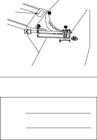
8.Install discharge chute rotator assembly into slot in housing with (3) 5/16 x 1º carriage bolt (head to top), (3) 5/16º pyramidal washer and (3)
5/16ºlocknut (Fig. 5).
9.Adjust rotator assembly so that worm gear is at right angle with chute, the teeth mesh fully and the chute turns freely. tighten locknut securely.
5
|
|
1 |
2 |
|
|
|
|
|
|
3 |
4 |
|
|
|
1280 |
|
|
Figure 5 |
|
1. |
Rotator assembly |
4. |
Locknut 5/16º |
2. |
Carriage bolt 5/16 x 1º |
5. |
Worm gear |
3. |
Pyramidal washer 5/16º |
|
|
Installing Snowthrower to Tractor
POTENTIAL HAZARD
•When snowthrower is attached to the tractor, without additional weight, the tractor may become unstable.
WHAT CAN HAPPEN
•Loss of traction and stability may cause loss of tractor control.
HOW TO AVOID THE HAZARD
•NEVER operate tractor, equipped with snowthrower, unless 100lb rear wheel weights are installed.
1.Install lift tube to housing with 5/8º flat washer and hairpin cotter (Fig. 6).
|
|
|
1 |
|
|
2 |
|
|
|
3 |
1288 |
|
|
Figure 6 |
|
1. |
Lift tube |
3. |
Hairpin cotter±large |
2. |
Washer 5/8º |
|
|
6
 Loading...