


71185
Toro 71185, 71188, 71189, 71190, 71193 Setup Instructions
...
FORM NO. 3318–186 Rev. B
WHEEL HORSE LAWN TRACTOR
FOR 32” AND 38” MOWERS
Loose Parts
Note: Use the chart below to verify all parts have been shipped.
DESCRIPTION QTY. USE
Front Wheel
Shim Washer (as required)
Flat Washer
Cotter Pin
Hub Cap
Steering Wheel
Spirol Pin
2
2
2
2
2
1
1
Install front wheels.
Install steering wheel.
SET-UP
INSTRUCTIONS
Seat
Knob
Flat Washer
Wire Clip (on seat pan)
Bolt 1/4–20 x 3/4”
Wing nut
Spring Hook 1 Used to install lift assist spring.
Key 2 Use in ignition switch.
Operator’s Manual
Safety Booklet
Safety Video
Registration Card 1 Fill out and mail the card.
1
1
1
1
2
2
1
1
1
Install the seat.
Install battery cables.
Read and watch before operating tractor.
The TORO Company – 1997
Printed in USA
All Rights Reserved
Set-Up Instructions
Install Front Wheels
Note: If wheels are already installed, refer to
Check Tire Pressure (below).
1. Install shim washers onto axle.
2. Install wheel onto axle with valve stem out.
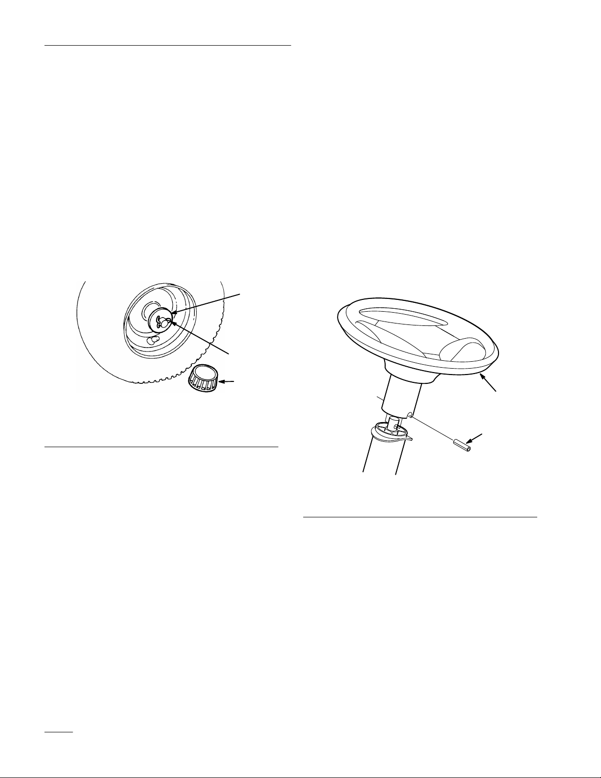
3. Slide the flat washer onto the axle. Insert cotter
pin through the axle and bend the ends of the pin
apart (Fig. 1). If cotter pin does not fit, remove
shim washer(s) as required.
4. Push the hub cap (Fig. 1) onto the end of the
axle.
1
2
Install Steering Wheel
1. Move front wheels straight ahead.
2. Slide the steering wheel over shaft. Line up the
hole in the steering wheel with the hole in the
shaft (Fig. 2). From the seat you should be able
to read the brand logo on the steering wheel.
3. To align the holes, insert a punch or long nail
partially through the holes in the steering wheel
and shaft. Then insert the spirol pin into the hole
on the opposite side.
4. Using a hammer, drive the spirol pin in until it is
flush with the outside of the steering wheel
(Fig. 2).
1904
1. Flat washer
2. Cotter pin
Figure 1
3. Hub cap
3
5. Repeat steps 1–4 on opposite side.
6. Grease the wheel bearings until grease comes out
of bearing seal area.
Check Tire Pressure
Check front and rear tire pressure. Set to 12 psi
(83 kPa).
1
2
1905
Figure 2
1. Steering wheel 2. Spirol pin
Install Seat
Note: If the seat is already installed, proceed
to Activate The Battery, page 3.
1. Insert seat switch wire cable through the hole in
the seat base (Fig. 3).
2. Position the seat onto the seat base by inserting
the two shoulder bolts through key hole
openings at the end of both slots (Fig. 3).
2
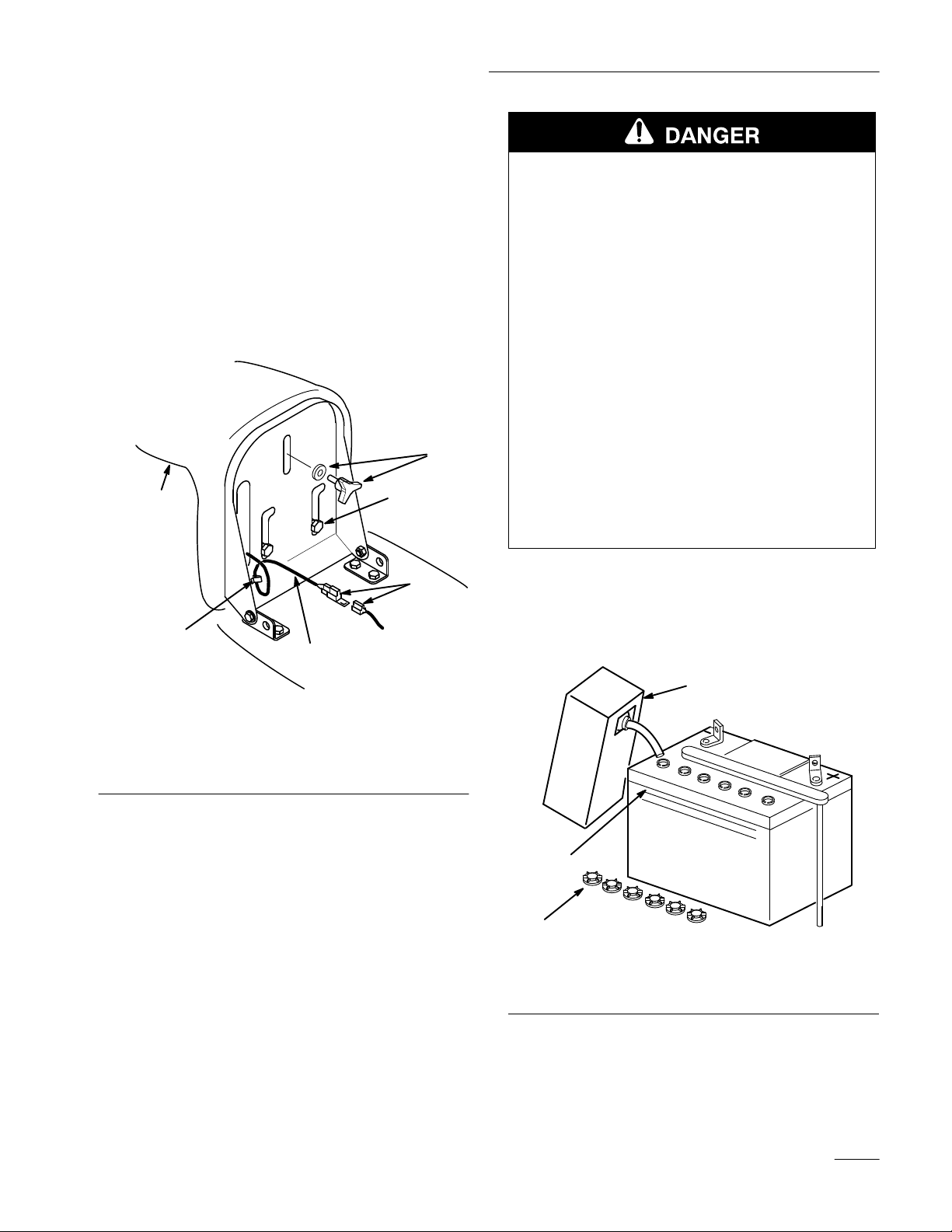
3. Thread the knob and flat washer into the rear
center hole in the seat (Fig. 3). Adjust the seat
and tighten the knob.
4. Push the seat switch connector fully into the
wire harness connector (Fig. 3).
5. Secure the seat switch wire cable to seat base
with wire clip (Fig. 3).
Note: Check seat switch wire routing, it must
not be pinched in seat brackets.
1
3
Set-Up Instructions
POTENTIAL HAZARD
• Battery electrolyte contains sulfuric acid
which is a deadly poison and it causes
severe burns.
WHAT CAN HAPPEN
• If you carelessly drink electrolyte you could
die or if it gets onto your skin you will be
burned.
HOW TO AVOID THE HAZARD
• Do not drink electrolyte and avoid contact
with skin, eyes or clothing. Wear safety
glasses to shield your eyes and rubber
4
gloves to protect your hands.
• Fill the battery where clean water is always
available for flushing the skin.
• Follow all instructions and comply with all
safety messages on the electrolyte container.
6
5
2
Figure 3
1. Seat
2. Wire and connector
3. Shoulder bolts
4. Knob and flat washer
5. Wire clip
6. Connectors
Activate the Battery
Bulk electrolyte with 1.260 specific gravity must be
purchased from a local battery supply outlet.
1. Remove the battery and battery box from the
tractor: refer to Operator’s Manual, Removing
the Battery.
2364
2. Unscrew six filler caps from the battery. Slowly
pour electrolyte into each cell until the level is
up to the “UPPER” line on the battery case
(Fig. 4).
2
3
1
1. Filler caps
2. Electrolyte
Figure 4
3. Upper line
1907
IMPORTANT: Be careful not to damage the
long vent tube when removing the battery
box.
3
 Loading...