


 Loading...
Form No. 3421-672 Rev A
20in Turf Seeder
Model No. 23508—Serial No. 400000000 and Up
Model No. 33512—Serial No. 400000000 and Up
Register at www.Toro.com. |
*3421-672* A |
Original Instructions (EN) |
It is a violation of California Public Resource Code Section 4442 to use or operate the engine on any forest-covered, brush-covered, or grass-covered land without a spark arrester muffler maintained in working order, or the engine constricted, equipped, and maintained for the prevention of fire. Other states or federal areas may have similar laws.
Because in some areas there are local, state, or federal regulations requiring that a spark arrester be used on the engine of this machine, a spark arrester is available as an option. If you require a spark arrester, contact your Authorized Service Dealer. Genuine Toro spark arresters are approved by the USDA Forestry Service.
The enclosed engine owner's manual is supplied for information regarding the US Environmental Protection Agency (EPA) and the California Emission
Control Regulation of emission systems, maintenance, and warranty. Replacements may be ordered through the engine manufacturer.
 WARNING
CALIFORNIA
Proposition 65 Warning
The engine exhaust from this product contains chemicals known to the State of California to cause cancer, birth defects, or other reproductive harm.
Use of this product may cause exposure to chemicals known to the State of California to cause cancer, birth defects, or other reproductive harm.
Introduction
This machine seeds, dethatches, and power rakes turf both for revitalizing existing turf and for spreading seed. It is intended for small to medium sized lawn applications in residential and commercial properties.
Read this information carefully to learn how to operate and maintain your product properly and to avoid injury and product damage. You are responsible for operating the product properly and safely.
You may contact Toro directly at www.Toro.com for product and accessory information, help finding a dealer, or to register your product.
Whenever you need service, genuine Toro parts, or additional information, contact an Authorized Service
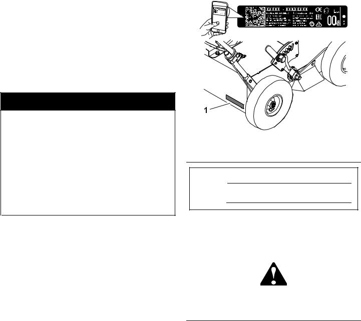
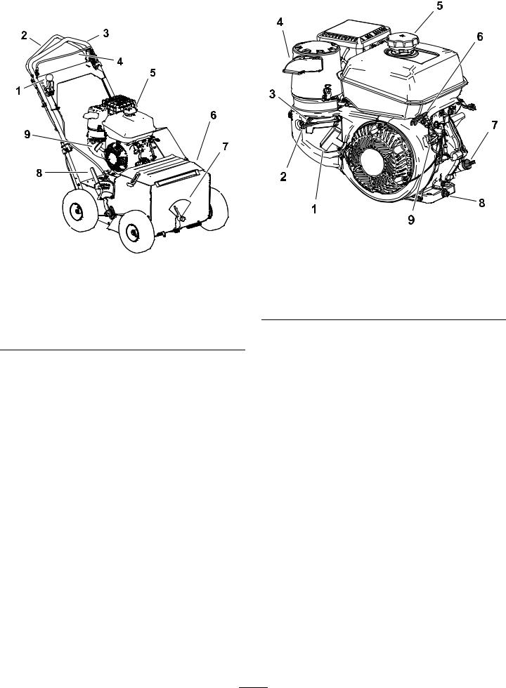
Dealer or Toro Customer Service and have the model and serial numbers of your product ready. Figure 1 identifies the location of the model and serial numbers on the product. Write the numbers in the space provided.
Important: With your mobile device, you can scan the QR code (if equipped) on the serial number decal or go to www.Toro.com to access warranty, parts, and other product information.
g252246
Figure 1
1.Model and serial number location
Model No.
Serial No.
This manual identifies potential hazards and has safety messages identified by the safety-alert symbol (Figure 2), which signals a hazard that may cause serious injury or death if you do not follow the recommended precautions.
g000502
Figure 2
Safety-alert symbol
This manual uses 2 words to highlight information. Important calls attention to special mechanical information and Note emphasizes general information worthy of special attention.
© 2018—The Toro® Company |
|
Contact us at www.Toro.com. |
|
8111 Lyndale Avenue South |
|
Printed in the USA |
|
2 |
|||
Bloomington, MN 55420 |
All Rights Reserved |

Contents |
|
Safety ....................................................................... |
4 |
General Safety ................................................... |
4 |
Safety and Instructional Decals .......................... |
5 |
Setup ........................................................................ |
8 |
1 Unfolding the Handle ....................................... |
8 |
2 Checking the Engine-Oil Level......................... |
8 |
Product Overview ..................................................... |
9 |
Controls ............................................................. |
9 |
Specifications ................................................... |
11 |
Torque Requirements ........................................ |
11 |
Attachments/Accessories.................................. |
11 |
Operation ................................................................ |
12 |
Before Operation Safety ................................... |
12 |
Adding Fuel ...................................................... |
12 |
Checking the Engine Oil ................................... |
14 |
Adjusting the Cutting-Blade Depth.................... |
14 |
Adjusting the Seeding-Rate Gauge................... |
14 |
Using the Seed Cover....................................... |
15 |
During Operation Safety ................................... |
15 |
Starting the Machine......................................... |
17 |
Shutting Off the Machine .................................. |
17 |
Operating the Self-Propel Drive ........................ |
17 |
Operating the Blade-Control Bail ...................... |
18 |
Operating the Machine ..................................... |
18 |
Operating Tips.................................................. |
19 |
After Operation Safety ...................................... |
20 |
Transporting the Machine ................................. |
20 |
Disengaging the Hydrostatic Drive.................... |
20 |
Maintenance ........................................................... |
21 |
Recommended Maintenance Schedule(s) ........... |
21 |
Pre-Maintenance Procedures .............................. |
22 |
Maintenance Safety.......................................... |
22 |
Disconnecting the Spark-Plug Wire .................. |
22 |
Lubrication .......................................................... |
23 |
Lubricating the Slicer-Shaft Bearings................ |
23 |
Engine Maintenance ........................................... |
23 |
Engine Safety ................................................... |
23 |
Servicing the Air Cleaner .................................. |
23 |
Servicing the Engine Oil.................................... |
24 |
Servicing the Spark Plug................................... |
26 |
Checking the Spark Arrester............................. |
26 |
Fuel System Maintenance ................................... |
27 |
Draining the Fuel Tank...................................... |
27 |
Drive System Maintenance .................................. |
27 |
Checking the Tire Pressure............................... |
27 |
Adjusting the Self-Propel Drive ......................... |
28 |
Changing the Hydraulic-Transmission |
|
Fluid.............................................................. |
28 |
Belt Maintenance ................................................ |
29 |
Checking the Condition of the Belts................... |
29 |
Adjusting the Self-Propel Drive-Belt |
|
Tension ......................................................... |
29 |
Cutting Blade Maintenance .................................. |
30 |
Checking and Replacing the Blades.................. |
30 |
Seed Gate Maintenance....................................... |
31 |
Checking the Seed Gate................................... |
31 |
Adjusting the Seed-Gate Closed |
|
Position......................................................... |
32 |
Cleaning .............................................................. |
32 |
Cleaning the Engine Area................................. |
32 |
Cleaning under the Machine ............................. |
32 |
Cleaning under the Belt Cover ......................... |
33 |
Cleaning the Seed Gate.................................... |
33 |
Storage ................................................................... |
34 |
Storage Safety.................................................. |
34 |
Storing the Machine.......................................... |
34 |
Removing the Machine from Storage................ |
34 |
Troubleshooting ...................................................... |
35 |
3

Safety
This machine has been designed in accordance with ANSI B71.4-2017. Improper use or maintenance by the operator or owner can result in injury. To reduce the potential for injury, comply with these safety instructions and always pay attention to the safety-alert symbol (Figure 2), which means Caution, Warning, or Danger—personal safety instruction. Failure to comply with the instruction may result in personal injury or death.
General Safety
This product is capable of injuring hands and feet and of throwing objects. Always follow all safety instructions to avoid serious personal injury.
Using this product for purposes other than its intended use could prove dangerous to you and bystanders.
•Read and understand the contents of this Operator’s Manual before starting the engine.
•Do not put your hands or feet near moving components of the machine.
•Do not operate the machine without all guards and other safety protective devices in place and working on the machine.
•Keep children and bystanders out of the operating area. Never allow children to operate the machine.
•Stop the machine and shut off the engine before servicing, fueling, or unclogging the machine.
Improperly using or maintaining this machine can result in injury. To reduce the potential for injury, comply with these safety instructions and always pay attention to the safety-alert symbol (Figure 2), which means Caution, Warning, or Danger—personal safety instruction. Failure to comply with these instructions may result in personal injury or death.
You can find additional safety information where needed throughout this manual.
4
Safety and Instructional Decals
Safety decals and instructions are easily visible to the operator and are located near any area of potential danger. Replace any decal that is damaged or missing.
decal93-7321
93-7321
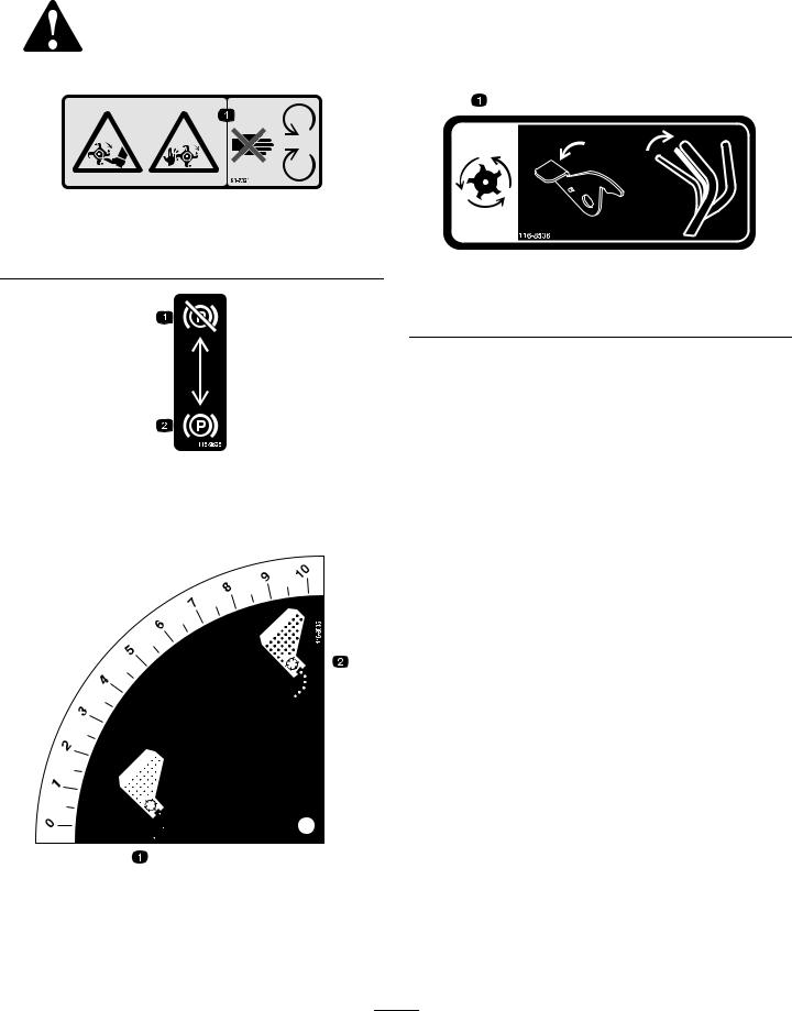
1.Cutting/dismemberment hazard of hands and feet, rotating knives/blades—stay away from moving parts.
decal116-8536
116-8536
1.Cutting blades - press down on lever and pull blade control bail against the handle to engage the cutting blades.
|
decal115-9625 |
|
115-9625 |
1. Parking |
2. Parking brake—engaged |
brake—disengaged |
|
|
|
decal116-8535
116-8535
1. Lower seed flow rate |
2. Higher seed flow rate |
|
|
5

decal116-8537
116-8537
decal116-8648
116-8648
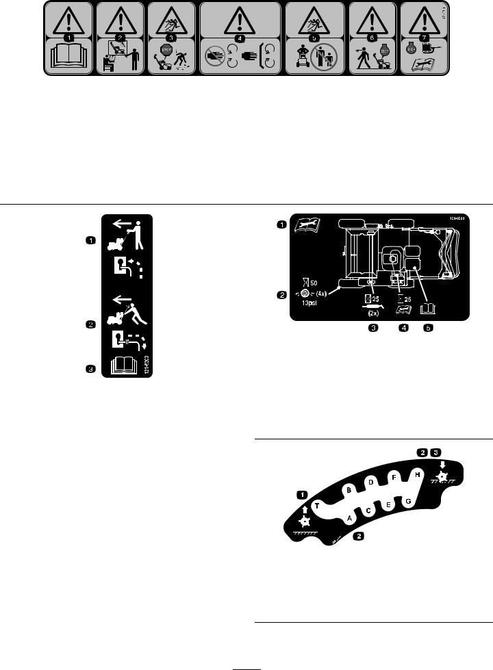
1.To start the engine, read the Operator’s Manual - (1) Park the machine on a level surface (2) Fill the engine with oil (3) Move the control bars to a neutral position (4) Start the engine.
2.Self-propel drive - push the self-propel drive bail forward to move the machine forward; pull the self-propel drive bail downward to move the machine backward.
3.Cutting blades - release the blade control bail (neutral position) to disengage the cutting blades; hold the blade control bail against the handle to engage the cutting blades.
4.Seed hopper on; seed hopper off.
117-2718 |
decal117-2718 |
decal117-4979 |
117-4979
1.Entanglement hazard, belt—keep away from moving parts; keep all guards and shields in place.
6
|
121-2011 |
|
decal121-2011 |
|
|
|
|
1. Warning—read the |
3. Thrown object hazard; pick 5. |
Thrown object |
7. Warning—shut off the |
Operator’s Manual. |
up debris before operating. |
hazard—keep bystanders |
engine and remove |
|
|
a safe distance from the |
the spark plug wire |
|
|
machine. |
before performing any |
|
|
|
maintenance on the |
|
|
|
machine. |
2.Warning—do not operate this machine unless you are trained.
4.Warning—keep hands away from moving parts, keep all guards and shields in place.
6.Warning—shut off the engine before leaving the machine.
decal121-6203
121-6203
1. |
Bypass lever position for |
3. Read the Operator’s |
|
operating the machine |
manual |
2. |
Bypass lever position for |
|
|
pushing the machine |
|
|
|
|
|
126-0296 |
decal126-0296 |
|
|
|
||
1. |
Read and understand the |
4. |
Check transmission belt |
|
operator’s manual before |
|
drive tension every 25 |
|
servicing this machine |
|
hours |
2. |
Check tire pressure—13 |
5. |
See engine owner’s |
|
psi (4x) every 50 hours |
|
manual for service |
3.Grease the slicer shaft bearings every 25 hours
decal126-2446
126-2446
1.Blade up; “T” = Transport position
3.“H” = deepest blade setting; blade down
2.“A” through “H” increasing depth settings
7
Setup
1
Unfolding the Handle
No Parts Required
Procedure
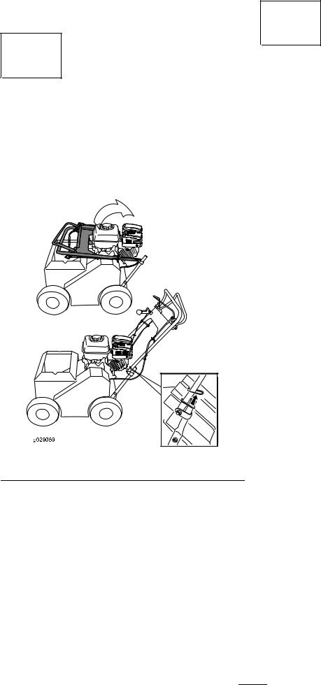
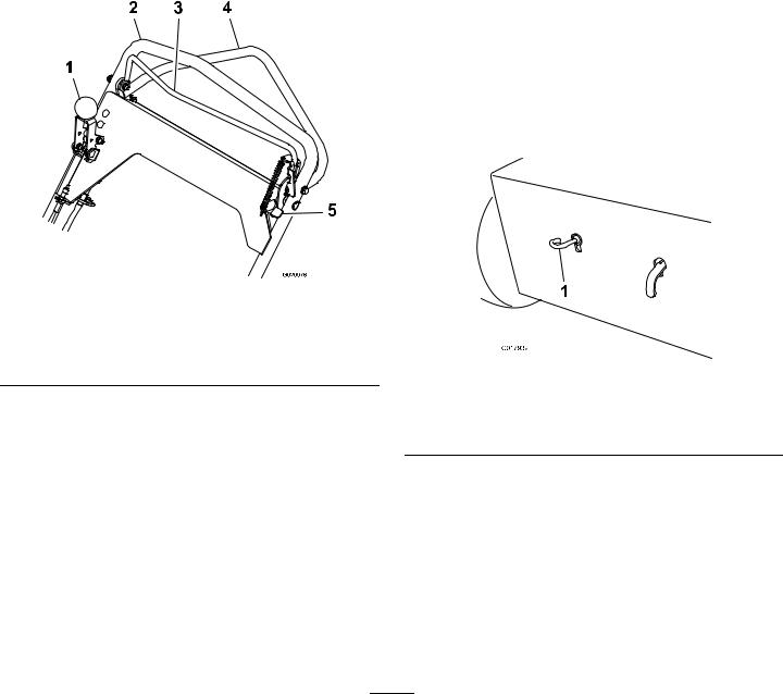
1.Raise the handle to the operating position (Figure 3).
2
Checking the Engine-Oil
Level
No Parts Required
Procedure
Refer to Checking the Engine-Oil Level (page 25).
g029059
Figure 3
2.Slide the oval locking rings down each side of the upper handle and over the lower handle (Figure 3), locking the handle sections together.
8
Product Overview
g252290
Figure 4
1. |
Seeder-control lever |
6. |
Seed hopper and cover |
2. |
Self-propel drive bail |
7. |
Seeding-rate gauge |
3. |
Handle |
8. |
Depth-control lever |
4. |
Blade-control bail |
9. |
Recoil-start handle |
5.Fuel-tank cap
g252291
|
|
Figure 5 |
|
1. |
Recoil-start handle |
6. |
Throttle lever |
2. |
Fuel-shutoff valve |
7. |
Dipstick |
3. |
Choke lever |
8. |
Oil-drain plug |
4. |
Air-cleaner |
9. |
On/Off switch |
5.Fuel-tank cap
Controls
Choke Lever
Before starting a cold engine, move the choke lever (Figure 5) to the left. After the engine starts, regulate the choke to keep the engine running smoothly. As soon as possible, move the choke lever all the way to the right.
Note: A warm engine requires little or no choking.
Throttle Lever
The throttle lever (Figure 5) is located on the engine and controls the engine speed. Moving the throttle lever rearward increases the engine speed, and moving the throttle lever forward decreases the engine speed.
Engine On/Off Switch
The engine on/off switch (Figure 5) is located on the front right-hand side of the engine. Rotate the switch clockwise to the ON position before starting the engine. Rotate the switch counterclockwise to the OFF position to shut off the engine.
9
Fuel-Shutoff Valve
The fuel-shutoff valve (Figure 5) is located on the engine and is used to shut off the fuel when the machine will not be used for a few days, during transport to and from the jobsite, and when parked inside a building.
Rotate it down to open it or up to close it.
Self-Propel Drive Bail
The self-propel drive bail (Figure 6), located under the handle, controls the forward and reverse motion of the machine.
When you squeeze the self-propel drive bail is against the handle, the ground speed of the machine changes based on the distance between the bail and the handle. When you release the bail, the machine stops moving.
Blade-Control Lock
The blade-control lock (Figure 6) is located on the left side of the handle, next to the blade-control bail.
Moving the blade-control lock into the full forward position allows the blade-control bail to be squeezed against the handle.
Squeezing the blade-control bail against the handle engages the blade. Releasing the blade-control bail automatically disengages the blade. The blade-control lock resets to lock the blade-control bail.
Seeder-Control Lever
The seeder-control lever (Figure 6) is located on the right handle bar.
Push the lever forward to start the seed flow, and pull it rearward to stop the seed flow.
Parking Brake
Set the parking brake whenever you leave the machine unattended and when performing maintenance. To engage the parking brake, pull the brake rod out and down, locking it in the out position. To disengage the brake, pull the brake up until it snaps back into the machine.
g020976
Figure 6
1. |
Seeder-control lever |
4. |
Self-propel drive bail |
2. |
Handle |
5. |
Blade-control lock |
3.Blade-control bail
Blade-Control Bail
The blade-control bail (Figure 6), located in front of the handle, engages or disengages the blade.
If the engine is running, the blades engage when you squeeze the blade-control bail toward the handle.
When you release the blade-control bail, the blades stop.
g017939
Figure 7
(Rear of machine shown)
1.Parking brake
10
Hydrostatic-Drive Bypass Lever
The hydrostatic-drive bypass lever (Figure 8) releases the hydrostatic-drive system so you can move the machine by hand, without the engine running.
For normal operating position, pull up on the handle and push the handle in until all 3 notches are inside the frame.
Note: The last notch on the handle does not latch on the slot.
To release the drive wheels, pull up on the handle and pull it out until the last notch engages in the slot. Then push the handle down.
g021333
Figure 8
1.Handle in—normal operating position
2.All notches inside frame
3.Handle out—hydrostatic-drive release
4.Last notch engaged in slot
Specifications
Note: Specifications and design are subject to change without notice.
Width |
76 cm (30 inches) |
|
|
Length (operating) |
137 cm (54 inches) |
|
|
Length (with handle stored) |
95.25 cm (37.5 inches) |
|
|
Height (operating) |
113 cm (44.5 inches) |
|
|
Height (with handle stored) |
73.5 cm (29 inches) |
|
|
Weight |
120.2 kg (265 lb) |
|
|
Torque Requirements
Bolt Location |
Torque |
|
|
Engine mounting bolts |
37 to 45 N m (27 to 33 ft-lb) |
Clutch mounting bolts |
66 to 83 N m (49 to 61 ft-lb) |
Slicer shaft nut |
88 to 115 N m (65 to 85 ft-lb) |
Attachments/Accessories
A selection of Toro approved attachments and accessories is available for use with the machine to enhance and expand its capabilities. Contact your Authorized Service Dealer or authorized Toro distributor or go to www.Exmark.com for a list of all approved attachments and accessories.
To ensure optimum performance and continued safety certification of the machine, use only genuine Toro replacement parts and accessories. Replacement parts and accessories made by other manufacturers could be dangerous, and such use could void the product warranty.
11
Loading...