


Building the
P-47 THUNDERBOLT
© 1976 - TOP FLITE MODELS, INC.
Congratulations!
You now own the most accurate R/C Stand-Off Scale kit ever produced.
We at Top Flite hope that you will find this model the most pleasant to build, inspiring to look at and exciting to fly that you have constructed.
It is honest to point out, however, that while this model is no more difficult - in fact is simpler than most comparable kits to make, R/C Scale models generally are not for the newcomer to this hobby. Previous modeling experience and careful attention to craftsmanship are necessary. Even the "old hand" will do well to study and follow the instructions and guidance given in this booklet.
It is our aim to have you say: "This is the finest model I have ever built."
TOP FLITE MODELS, INC.
ACKNOWLEDGEMENTS
The staff of Top Flite wishes to acknowledge the assistance of the following individuals who contributed their time and talent to the successful creation of this kit:
Col. JIM G1LHULY (USAF RET.)
ART SCHROEDER
ART SAB1N
CLARK MACOMBER
Top Flite Models, Inc.
WARNING
A RADIO CONTROLLED MODEL IS NOT A "TOY". CARE AND CAUTION MUST BE TAKEN IN PROPERLY BUILDING THE MODEL AS WELL AS IN THE INSTALLATION AND USE OF THE RADIO CONTROL DEVICE. IT IS IMPORTANT TO FOLLOW ALL DIRECTIONS AS TO CONSTRUCTION OF THIS KIT AS WELL AS INSTALLATION A N D USE OF THE ENGINE A N D RADIO GEAR. THE ADVICE A N D ASSISTANCE OF A WELL-EXPERIENCED BUILDER A N D PILOT ARE ESSENTIAL. DON'T TAKE CHANCES. IMPROPER BUILDING, OPERATION OR FLYING OF THIS MODEL MAY RESULT IN SERIOUS BODILY I N J U R Y TO OTHERS, TO YOURSELF OR PROPERTY DAMAGE.

THE P-47 STORY
The P47 was produced in larger numbers than any other U.S. Fighter of WWII. 15,683 production versions ranged from the P47-B, C, D, E, F, G, H, J, M, and N. Somewhat overshadowed by the publicity accorded the "Mustang" and the "Spitfire", the "Thunderbolt" was, nonetheless a most distinguished and respected aircraft by friend and foe alike.
The first P47 was test flown in May, 1941 and was known as the XP-47B. This aircraft was designed to fill the need for a fighter aircraft able to exceed the anticipated ceilings of enemy bombers, out gun them offensively; to escort and provide cover for American bombers flying in the Substratosphere, and to out-gun enemy interceptors.
The first production models were assigned to fighter units in England where it became extremely popular with AAF Pilots because of its ability to absorb extensive battle damage and still remain flying.
Perhaps the most outstanding tribute to this aircraft is the fact that all ten of the
leading Thunderbolt |
"Aces" |
survived |
the war. Colonel Glenn T. Eagleston was one of these. |
||||
This kit is the P47D-25-RE version |
flown by Colonel Eagleston while a member of the |
||||||
35rd Sq, |
354th |
Gp, |
19th |
Tactical |
Air |
Force commanded by General O.P. Weyland. |
|
Col. Eagleston was the top |
"Ace" |
of the |
ninth Air Force, credited with 23'/2 destroyed, 2 |
||||
probables |
and 7 |
damaged |
enemy |
aircrafts. It is to Colonel Eagleston that this kit is re- |
|||
spectfully dedicated. |
|
|
|
|
|
||
References: Aero Publishers, Inc. |
|
|
Camouflage & Markings |
||||
|
329 Aviation Road |
|
|
Ducemus Books, Ltd. |
|||
|
Fallbrook, California |
|
|
London, England |
|||
|
Thunderbolt in Action |
|
U.S. Army & Air Force Markings, 1916-1961 |
||||
|
3461 E. Ten Mile Road |
|
Library of Congress Card No. 61-16739 |
||||
|
Warren, Michigan 48091 |
|
|
||||
CONSTRUCTION OF P-47
BEFORE YOU START, READ THIS:
The assembly sequence of your Top Flite P47 has been carefully developed to help assure the correct alignment of your model. Utilize the check-off blocks as you build; this will allow assembly of your model in minimum time.
Before beginning an assembly step, read the instructions to familiarize yourself with the parts to be used. Find the parts mentioned and double check them for proper identification and size with the plans. Do nut separate parts from the die cut sheets u n t i l you need them. There are machined parts in your kit which are not identified, such as the fuselage siders, stab, ailerons, etc. These parts can be easily identified by checking the parts against the plans.
We are sometimes asked which glues are best for model construction. The answer to this depends upon the particular job. This is our normal recommendation: For all hardwood-to-hardwoud or hardwood-to-balsa joints, use white wood glue. "Titebond" is especially good, as it dries faster than other white glues and is very strong. For balsa-to- balsa joints, regular balsa-wood cements are ample for the job, although white glue can be used here too. Whichever type you use, remember that excess glue is no substitute for a w e l l - f i t t i n g joint. Use a m i n i m u m of glue at all times, and wipe off excess glue that squeezes out of joints before it sets hard; when set it is difficult to remove, but if not removed it could spoil the covering job.
1
CONSTRUCTION
SEQUENCE
Follow each step in order and put check marks in the blocks as you complete each phase described.
FUSELAGE
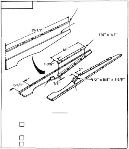
1/4" x 1/2" NOTCHED STRIPS
NOTE CURVED TOP EDGE
NOTCHED STRIPS
|
|
HARDWOOD |
|
F-31 |
(PLY) |
WING SCREW BLOCK |
|
F-31 (PLY) |
|||
|
|
||
RIGHT |
|
LEFT FUSELAGE SIDE |
|
FUSELAGE SIDE |
|
|
FIG. 1
STEP
1
Glue 1/4 x 1/2 notched balsa strips to fuselage sides. Make a right and left side. Note: Curve on top edge of fuselage sides is intentional.
Glue ply braces F-31 to fuselage sides. (See plans for position)
Glue hardwood wing screw blocks in place.
2
FUSELAGE |
F-5 |
F-3B |
F-7 (PLY) |
|
USE TRIANGLE OR
SQUARE TO CHECK
ALIGNMENT.
F-5SPACERS
HARDWOOD MOTOR MOUNTS
S T E P
2
FIG. 2
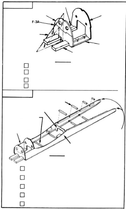
Glue F-3A and F-3B together.
Pin F-5 spacers over bottom view of plans BETWEEN F-3AB and F-7.
Glue motor mounts to the two F-5's.
Glue F-3AB assembly and F-7 (ply) vertical in position.
F U S E L A G E
1/4" SQ. SPACERS
F-17 (PLY)
BULKHEAD SPACER FOR F-8
MOTOR MOUNT
ASSEMBLY
TRIM TO 1/8" EACH
SIDE, GLUE, AND
CLAMP TOGETHER
FUSELAGE SIDE
|
FIG. 3 |
STEP |
Using bottom view of plans, cut 1/4 SQ. bulkhead spacers from |
3 |
1/4 x 1/4 x 36 balsa strips. |
Glue MOTOR MOUNT ASSEMBLY to fuselage sides over |
|
bottom view of plans. |
|
|
Starting with bulkhead spacer for F-8, glue and pin spacers in |
|
place, working toward rear. |
|
Glue F-17 (ply) in place. (Check plans for position). Hold |
|
fuselage sides together with tape if necessary. |
|
Trim rear, glue, and clamp together. |
3
 Loading...