


Wingspan: 81 in [2057mm] Wing Area: 914 sq in [58.9dm2] Weight: 17-20 lb [7710-9070g]
Wing Loading: 43-50 oz/sq ft [131-153g/dm2]
Length: 66 in [1680mm]
Radio: 6-Channel minimum w/8 servos (8- or 9-channel w/9 servos required for optional retracts)
Engines (2): .46-.51 cu in [7.5-8.5 cc] 2-stroke or
.70-.80 cu in [11.5-13 cc] 4-stroke
Model from date of
Top kit. modify
or be
assumed nor accepted for any damage resulting from the use by the user of the final user-assembled product. By the act of using the user-assembled product, the user accepts all resulting liability.
If the buyer is not prepared to accept the liability associated with the use of this product, the buyer is advised to return this kit immediately in new and unused condition to the place of purchase.
To make a warranty claim send the defective part or item to Hobby Services at the following address:
Hobby Services
3002 N. Apollo Dr. Suite 1
Champaign IL 61822
USA
Include a letter stating your name, return shipping address, as much contact information as possible (daytime telephone number, fax number, e-mail address), a detailed description of the problem and a photocopy of the purchase receipt. Upon receipt of the package the problem will be evaluated as quickly as possible.
CONSTRUCTION. IT CONTAINS IMPORTANT INSTRUCTIONS AND WARNINGS CONCERNING THE ASSEMBLY AND USE OF THIS MODEL.
Telephone (217) 398-8970, Ext. 5 |
airsupport@top-flite.com |
Entire |
TOPZ0910 for TOPA0910 V1.0 |

TABLE OF CONTENTS
INTRODUCTION . . . . . . . . . . . . . . . . . . . . . . . . 2 SAFETY PRECAUTIONS . . . . . . . . . . . . . . . . . . 3
DECISIONS YOU MUST MAKE . . . . . . . . . . . . . 3 Radio Equipment . . . . . . . . . . . . . . . . . . . . 3 Engine Recommendations . . . . . . . . . . . . . 4 Optional Retractable Landing Gear . . . . . . . 4
ADDITIONAL ITEMS REQUIRED. . . . . . . . . . . . 4 Adhesives and Building Supplies. . . . . . . . . 4 Optional Supplies and Tools . . . . . . . . . . . . 4
IMPORTANT BUILDING NOTES . . . . . . . . . . . . 4 ORDERING REPLACEMENT PARTS. . . . . . . . . 5
KIT CONTENTS . . . . . . . . . . . . . . . . . . . . . . . . . 6 PREPARATIONS . . . . . . . . . . . . . . . . . . . . . . . . 7
ASSEMBLE THE FUSELAGE STAND . . . . . . . . 7
ASSEMBLE THE WING . . . . . . . . . . . . . . . . . . . 7 Install the Ailerons and Flaps . . . . . . . . . . . 7 Mount the Plywood Engine Nacelles . . . . . . 9 Install the Flap, Throttle and Aileron
Servos and Pushrods . . . . . . . . . . . . . . . 9 Mount the Wing Tip to the Wing. . . . . . . . . 11 Install the Engine and Fuel Tank . . . . . . . . 12 Install the Fiberglass Nacelles . . . . . . . . . . 13 Install the Spinners . . . . . . . . . . . . . . . . . . 14 Join the Wings . . . . . . . . . . . . . . . . . . . . . 14
ASSEMBLE THE FUSELAGE . . . . . . . . . . . . . 15 Install the Elevator and Rudder . . . . . . . . . 15 Install the Cockpit . . . . . . . . . . . . . . . . . . . 17 Install the Radio, Elevator
and Rudder Servos. . . . . . . . . . . . . . . . 18
INSTALL THE LANDING GEAR . . . . . . . . . . . . 19 Nose Gear . . . . . . . . . . . . . . . . . . . . . . . . 19 Main Gear. . . . . . . . . . . . . . . . . . . . . . . . . 20
RETRACTABLE LANDING GEAR . . . . . . . . . . 22 Nose Gear . . . . . . . . . . . . . . . . . . . . . . . . 22 Main Gear. . . . . . . . . . . . . . . . . . . . . . . . . 23 Install the Retract Hardware . . . . . . . . . . . 25 FINAL ASSEMBLY. . . . . . . . . . . . . . . . . . . . . . 26 Completing the Radio Installation . . . . . . . 26 Connecting the Lighting System . . . . . . . . 26 Apply the Decals. . . . . . . . . . . . . . . . . . . . 27
GET THE MODEL READY TO FLY . . . . . . . . . . 27 Check the Control Directions . . . . . . . . . . . 27 Set the Control Throws . . . . . . . . . . . . . . . 28
Balance the Model (C.G.) . . . . . . . . . . . . . 28
Balance the Model Laterally . . . . . . . . . . . 28
Adjusting the Retractable Landing Gear. . . 29
PREFLIGHT . . . . . . . . . . . . . . . . . . . . . . . . . . . 29
Identify Your Model . . . . . . . . . . . . . . . . . . 29
Charge the Batteries . . . . . . . . . . . . . . . . . 29
Balance Propellers . . . . . . . . . . . . . . . . . . 29
Ground Check. . . . . . . . . . . . . . . . . . . . . . 29
Range Check . . . . . . . . . . . . . . . . . . . . . . 30
ENGINE RUN IN INSTRUCTIONS . . . . . . . . . . 30
ENGINE SAFETY PRECAUTIONS . . . . . . . . . . 30
AMA SAFETY CODE . . . . . . . . . . . . . . . . . . . . 31
IMAA SAFETY CODE . . . . . . . . . . . . . . . . . . . 31
CHECK LIST . . . . . . . . . . . . . . . . . . . . . . . . . . 33
FLYING . . . . . . . . . . . . . . . . . . . . . . . . . . . . . . 33
Takeoff . . . . . . . . . . . . . . . . . . . . . . . . . . . 34
Flight . . . . . . . . . . . . . . . . . . . . . . . . . . . . 34
Landing. . . . . . . . . . . . . . . . . . . . . . . . . . . 34
Engine Out Procedure. . . . . . . . . . . . . . . . 34
INTRODUCTION
Congratulations on the purchase of your Cessna 310! This is one of the finest ARF aircraft we have ever produced. It is an airplane that is sure to turn heads at the field and get everyone’s attention as soon as you are airborne. The molded fiberglass fuselage and wing tips have faithfully re-created this classic twin with many fine details and a tremendous paint finish. Many of the bad tendencies of twin engine aircraft have been engineered out of this model so this plane is easily within the capability of the average intermediate pilot. We are sure this plane will bring you many hours of flying enjoyment!
For the latest technical updates or manual corrections to the Cessna 310 visit the Top Flite web site at www.top-flite.com. Open the “Airplanes” link, then select the Cessna 310 ARF. If there is new technical information or changes to this model a “tech notice” box will appear in the upper left corner of the page.
- 2 -
AMA
In addition to joining a radio control club, we strongly recommend you join the AMA (Academy of Model Aeronautics). The AMA is the governing body of model aviation and membership is required to fly at AMA clubs. Though joining the AMA provides many benefits, one of the primary reasons to join is liability protection. Coverage is not limited to flying at contests or on the club field. It even applies to flying at public demonstrations and air shows. Failure to comply with the Safety Code (excerpts printed in the back of the manual) may endanger insurance coverage. Additionally, training programs and instructors are available at AMA club sites to help you get started the right way. There are over 2,500 AMA chartered clubs across the country. Contact the AMA at the address or toll-free phone number below:
Academy of Model
Aeronautics
5151 East Memorial Drive
Muncie, IN 47302-9252
Tele. (800) 435-9262
Fax (765) 741-0057 Or via the Internet at: www.modelaircraft.org
IMPORTANT!!!
Two of the most important things you can do to preserve the radio controlled aircraft hobby are to avoid flying near full-scale aircraft and avoid flying near or over groups of people.

IMAA
The Top Flite Cessna 310 is an excellent sport-scale model and is eligible to fly in IMAA events. The IMAA (International Miniature Aircraft Association) is an organization that promotes non-competitive flying of giant-scale models. If you plan to attend an IMAA event, obtain a copy of the IMAA Safety Code by contacting the IMAA at the following address or telephone number, or by logging on to their web site.
IMAA
205 S. Hilldale Road
Salina, KS 67401 (913) 823-5569
www.fly-imaa.org/imaa/sanction.html.
SCALE COMPETITION
Though the Top Flite Cessna 310 is an ARF and may not have the same level of detail as an “all-out” scratch-built competition model, it is a scale model nonetheless and is therefore eligible to compete in the Fun Scale class in AMA competition (we receive many favorable reports of Top Flite ARFs in scale competition!). In Fun Scale, the “builder of the model” rule does not apply. To receive the five points for scale documentation, the only proof required that a full size aircraft of this type in this paint/markings scheme did exist is a single sheet such as a kit box cover from a plastic model, a photo, or a profile painting, etc. If the photo is in black and white other written documentation of color must be provided. Contact the AMA for a rule book with full details.
If you would like photos of full-size Cessna 310s for scale documentation, or if you would like to study the photos to add more scale details, photo packs are available from:
Bob’s Aircraft Documentation
3114 Yukon Ave
Costa Mesa, CA 92626 Telephone: (714) 979-8058 Fax: (714) 979-7279 www.bobsairdoc.com
PROTECT YOUR MODEL, YOURSELF & OTHERS FOLLOW THESE IMPORTANT SAFETY PRECAUTIONS
1.Your Cessna 310 should not be considered a toy, but rather a sophisticated, working model that functions very much like a full-size airplane. Because of its performance capabilities, the Cessna 310, if not assembled and operated correctly, could possibly cause injury to yourself or spectators and damage to property.
2.You must assemble the model according to the instructions. Do not alter or modify the model, as doing so may result in an unsafe or unflyable model. In a few cases the instructions may differ slightly from the photos. In those instances the written instructions should be considered as correct.
3.You must take time to build straight, true and strong.
4.You must use an R/C radio system that is in firstclass condition, and correctly sized engines and components (fuel tank, wheels, etc.) throughout the building process.
5.You must correctly install all R/C and other components so that the model operates correctly on the ground and in the air.
6.You must check the operation of the model before every flight to insure that all equipment is operating and that the model has remained structurally sound. Be sure to check clevises or other connectors often and replace them if they show any signs of wear or fatigue.
7.If you are not an experienced pilot or have not flown this type of model before, we recommend that you get the assistance of an experienced pilot in your R/C club for your first flights. If you’re not a member of a club, your local hobby shop has information about clubs in your area whose membership includes experienced pilots.
-3 -
8. WARNING: The cowl, fuselage, nacelles and tail cone included in this kit are made of fiberglass, the fibers of which may cause eye, skin and respiratory tract irritation. Never blow into a part to remove fiberglass dust, as the dust will blow back into your eyes. Always wear safety goggles, a particle mask and rubber gloves when grinding, drilling and sanding fiberglass parts. Vacuum the parts and the work area thoroughly after working with fiberglass parts.
We, as the kit manufacturer, provide you with a top quality, thoroughly tested kit and instructions, but ultimately the quality and flyability of your finished model depend on how you build it; therefore, we cannot in any way guarantee the performance of your completed model, and no representations are expressed or implied as to the performance or safety of your completed model.
Remember: Take your time and follow the instructions to end up with a well-built model that is straight and true.
DECISIONS YOU MUST MAKE
This is a partial list of items required to finish the Cessna 310 that may require planning or decision making before starting to build. Order numbers are provided in parentheses.
RADIO EQUIPMENT
Transmitter and Receiver
A minimum of a 6 channel radio is required but because of the number of servos in this model you may wish to eliminate the use of “Y” connectors. An 8- or 9- channel radio may be preferable.
Servos
(2) 40 oz-in servos for the throttles
(1) 40 oz-in servo for the retract (optional)
(6) 54 oz-in servos 2-flaps, 2-ailerons, 1-rudder, 1-elevator
Servo Extensions
(3)Y-harness (HCAM2751 for Futaba®)
(4)6" [150mm] extension (HCAM2701 for Futaba)
(2)12" [300mm] extension (HCAM2711 for Futaba)
(4)24" [610mm] extension (HCAM2721 for Futaba)
Batteries
1000 mAh NiCd battery for the receiver
500 mAh NiCd battery for the lighting system
ENGINE RECOMMENDATIONS
Engine
The recommended engine size for the Cessna 310 is a .46-.50 two-stroke. This airplane was extensively flown on the O.S.® .46AX two stroke engines and Bisson muffler. Though your instincts might tell you that a plane of this size and weight will be underpowered with these engines, this is not true. During our test flights we used these engines for taking off from grass and asphalt with no problems. The climb out from take off was impressive. Once the plane was at altitude the plane was flown at 1/2 to 3/4 throttle. As part of our testing the plane was flown on a single engine from both the right and left nacelle. The O.S. .46 was enough power to maintain flying altitude, fly a figure eight, and a rectangle approach to the runway. The airplane has the power to fly on one engine but not enough to climb out from a missed landing approach. The O.S. .46 or .50 SX is the engine of choice to keep everything hidden under the nacelle.
Muffler
The Bisson Pitts Muffler (BISG4046) fits very well in the nacelle and is the recommended after market muffler for the Cessna 310.
OPTIONAL RETRACTABLE
LANDING GEAR
Robart Cessna 310 Retracts (ROBQ1623) Robart Standard Air Kit with variable
rate valve (ROBQ2302)
10' [1meter] Pressure tubing (ROBQ2369)
(2) Air line quick disconnects (ROBQ2395)
ADDITIONAL ITEMS REQUIRED
ADHESIVES & BUILDING SUPPLIES
This is the list of Adhesives and Building Supplies that are required to finish the Cessna 310.
3' [900mm] standard silicone fuel tubing (GPMQ4131)
1/2 oz. [15g] Thin Pro™ CA (GPMR6001)
1 oz. [30g] Medium Pro CA+ (GPMR6008)
Pro 30-minute epoxy (GPMR6047)
Pro 6-minute epoxy (GPMR6045)
Drill bits: 1/16" [1.6mm], 5/64" [2mm], 3/32" [2.4mm], 7/64" [2.8mm], 1/8" [3.2mm], 11/64" [4.4mm]
Silver solder w/flux (GPMR8070)
#1 Hobby knife (HCAR0105)
#11 blades (5-pack, HCAR0211)
Medium T-pins (100, HCAR5150)
Masking tape (TOPR8018)
Threadlocker thread locking cement (GPMR6060)
Denatured alcohol (for epoxy clean up)
Hot melt glue and glue gun (available at hobby, craft and hardware outlets)
OPTIONAL SUPPLIES & TOOLS
Here is a list of optional tools mentioned in the manual that will help you build the Cessna 310.
21st Century® sealing iron (COVR2700)
21st Century iron cover (COVR2702)
4 oz. [113g] aerosol CA activator (GPMR634)
CA applicator tips (HCAR3780)
Epoxy brushes (6, GPMR8060)
Mixing sticks (50, GPMR8055)
Mixing cups (GPMR8056)
Hobbico Duster™ compressed air (HCAR5500)
Rotary tool such as Dremel®
Rotary tool reinforced cut-off wheel (GPMR8020)
Servo horn drill (HCAR0698)
Dead Center™ Engine Mount Hole Locator (GPMR8130)
AccuThrow™ Deflection Gauge (GPMR2405)
CG Machine™ (GPMR2400)
Precision Magnetic Prop Balancer (TOPQ5700)
-4 -
IMPORTANT BUILDING NOTES
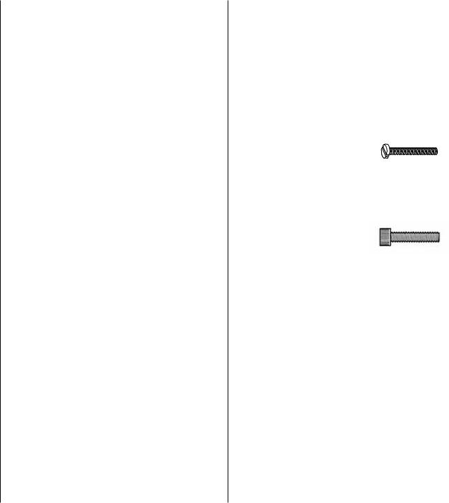
• There are two types of screws used in this kit:
Sheet metal screws are designated by a number and a length. For example #6 x 3/4" [19mm]
This is a number six screw that is 3/4" [19mm] long.
Machine screws are designated by a number, threads per inch, and a length. For example 4-40 x 3/4" [19mm]
This is a number four screw that is 3/4" [19mm] long with forty threads per inch.
Socket head cap screws are designated by a number, threads per inch and a length. For example 4-40 x 3/4" [19mm]
This is a number four screw that is 3/4" [19mm] long with forty threads per inch.
•When you see the term test fit in the instructions, it means that you should first position the part on the assembly without using any glue, and then slightly modify or custom fit the part as necessary for the best fit.
•Whenever the term glue is written you should rely upon your experience to decide what type of glue to use. When a specific type of adhesive works best for that step, the instructions will make a recommendation.
•Whenever just epoxy is specified you may use either 30-minute (or 45-minute) epoxy or 6-minute epoxy. When 30-minute epoxy is specified it is highly recommended that you use only 30-minute (or 45-minute) epoxy, because you will need the working time and/or the additional strength.
•Photos and sketches are placed before the step they refer to. Frequently you can study photos in following steps to get another view of the same parts.

•The Cessna 310 is factory-covered with Top Flite MonoKote® film. Should repairs ever be required, MonoKote can be patched with additional MonoKote purchased separately. MonoKote is packaged in sixfoot rolls, but some hobby shops also sell it by the foot. If only a small piece of MonoKote is needed for a minor patch, perhaps a fellow modeler would give you some. MonoKote is applied with a model airplane covering iron, but in an emergency a regular iron could be used. A roll of MonoKote includes full instructions for application. Following are the colors used on this model and order numbers for six foot rolls.
White - TOPQ0204 Sky Blue - TOPQ0206
Insignia Blue - TOPQ0207
METRIC CONVERSIONS
To convert inches to millimeters, multiply inches by 25.4
.4mm = 1/64"
.8mm = 1/32" 1.6mm = 1/16" 2.4mm = 3/32" 3.2mm = 1/8"
4mm = 5/32" 4.8mm = 3/16" 6.4mm = 1/4"
9.5mm = 3/8" 12.7mm = 1/2" 15.9mm = 5/8"
19mm = 3/4" 25.4mm = 1" 50.8mm = 2" 76.2mm = 3"
152.4mm = 6" 304.8mm = 12" 381mm = 15" 457.2mm = 18" 533.4mm = 21" 609.6mm = 24" 762mm = 30" 914.4mm = 36"
ORDERING REPLACEMENT PARTS
Replacement parts for the Top Flite Cessna 310 are available using the order numbers in the Replacement Parts List that follows. The fastest, most economical service can be provided by your hobby dealer or mail-order company.
To locate a hobby dealer, visit the Hobbico web site at www.hobbico.com. Choose “Where to Buy” at the bottom of the menu on the left side of the page. Follow the instructions provided on the page to locate a U.S., Canadian or International dealer.
Parts may also be ordered directly from Hobby Services by calling (217) 398-0007, or via facsimile at (217) 398-7721, but full retail prices and shipping and handling charges will apply. Illinois and Nevada residents will also be charged sales tax. If ordering via fax, include a Visa® or MasterCard® number and expiration date for payment.
Mail parts orders and payments by personal check to:
Hobby Services
3002 N Apollo Drive, Suite 1
Champaign IL 61822
Be certain to specify the order number exactly as listed in the Replacement Parts List. Payment by credit card or personal check only; no C.O.D.
If additional assistance is required for any reason contact Product Support at:
(217) 398-8970 productsupport@greatplanes.com
- 5 -
REPLACEMENT PARTS LIST
Description |
How to purchase |
Missing pieces |
Contact Product Support |
Instruction manual |
Contact Product Support |
Full-size plans |
Not available |
Order # |
Description |
TOPA1660 |
Wing Set |
TOPA1661 |
Fuselage Set |
TOPA1662 |
Wing Tip Set |
TOPA1663 |
Tail Set |
TOPA1664 |
Left Engine Pod |
TOPA1665 |
Right Engine Pod |
TOPA1666 |
Landing Gear |
TOPA1667 |
Decal Set |
TOPA1668 |
Wing Tubes (2) |
TOPA1669 |
Tail Tubes (2) |
TOPA1670 |
Windshield/Windows |
TOPA1671 |
Gear Doors |
TOPA1672 |
Aluminum Spinner |
TOPA1673 |
Tail Cone |
TOPA1674 |
Rudder |
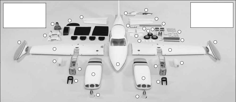
KIT CONTENTS
1. |
Fuselage |
|
|
|
|
2. |
Nacelles (L&R) |
|
26 |
|
|
3. |
Spinners |
|
25 |
|
|
4. |
Engine Mounts |
|
24 |
|
24 |
5. |
Fuel Tanks |
|
13 |
|
|
|
|
|
|||
|
|
|
22 |
||
6. |
Wood Nacelle (Left) |
14 |
23 |
|
|
|
|
|
|||
|
|
|
15 |
|
19 |
|
|
|
|
18 |
|
|
|
|
|
20 |
|
|
|
|
|
|
14.Pilot
15.Wing Fairing (L&R)
16.Gear Door (L&R)
17.Landing Gear Covers
18.Wheels
19.Landing Gear
|
|
12 |
|
|
|
|
|
|
16 |
|
|
|
|
|
|
10 |
|
|
|
|
|
|
17 |
21 |
11 |
|
|
|
|
|
|
|
|
|
|
|
|
||||
|
|
|
|
|
|
|
|
|
|
|
|||
|
|
|
|
9 |
|
|
|
|
8 |
|
|
|
|
|
|
|
|
|
|
|
|
|
|
|
|
|
|
|
|
|
|
5 |
|
|
|
|
|
5 |
|
|
|
|
|
|
|
|
|
|
1 |
|
|
|
|
||
|
|
|
|
|
|
|
6 |
|
|
|
|
||
|
|
|
|
|
|
|
|
|
|
|
|
|
|
|
|
|
|
|
|
7 |
|
|
|
|
|
|
|
|
7. |
Wood Nacelle (Right) |
|
|
|
2 |
|
|
|
|
|
20. Servo and Battery Tray |
|
|
8. |
Wing Half (Left) |
|
|
|
|
|
|
|
|
21. Wing Joiner Tubes |
|
|
|
|
|
|
|
|
|
2 |
|
|
|
|||
|
9. |
Wing Half (Right) |
|
|
|
|
|
|
|
|
22. Stab Tubes |
|
|
|
|
|
|
4 |
|
|
4 |
|
|
|
|||
|
10. Wing Tip (Right) |
|
|
|
|
|
|
|
|
|
23. Elevator Joiner Wire |
|
|
|
11. Wing Tip (Left) |
|
|
|
|
|
|
|
|
|
24. Stabilizer (L&R) |
|
|
|
12. Lower Nacelle Covers |
|
|
|
3 |
|
|
|
|
|
25. Rudder Control Wire |
|
|
|
13. Cockpit Kit |
|
|
|
|
|
3 |
|
|
26. Rudder |
|
||
|
|
|
|
|
|
|
|
|
|
||||
|
|
|
|
|
|
|
|
|
|
|
|
|
|
|
|
|
|
|
|
|
|
|
|
|
|
|
|
|
|
|
|
|
|
|
|
|
|
|
|
|
|
|
PARTS NOT PHOTOGRAPHED |
|
(2) |
Large Black Control Horn |
|
(8) |
#2 x 3/8" [10mm] Wood Screw |
(4) |
Flat Nylon Strap |
||||
|
|
|
|
|
(1) |
2-56 Nylon Ball Link Socket |
|
(2) |
8-32 x 1" [25mm] SHCS |
(4) |
Humped Landing Gear Strap |
||
(2) |
2-56 Metal Clevis |
|
(4) |
Nylon Retainer |
|
(4) |
4-40 x 1/8" [3mm] SHS |
(3) |
4x200mm Nylon Tie Strap |
||||
(1) |
4-40 Threaded Metal Clevis |
|
(2) |
CA Hinge Strip |
|
(8) |
#2 x 1/2" [13mm] SMS |
(1) |
.5 x 1000mm Cable |
||||
(2) |
4-40 Solder Clevis |
|
(5) |
Faslink |
|
(2) |
.074 x12" Wire [305mm] |
(2) |
8x40mm Nylon Dowel with Pin |
||||
(4) |
Brass Screw Lock Connector |
|
(2) |
36" Gray outer Pushrod Tube |
|
(5) |
.074 x 6" [152mm] Wire |
(4) |
8x30mm Nylon Dowel |
||||
(2) |
4-40 Nut |
|
(9) |
Silicone Clevis Keeper |
|
(2) |
4-40 x 36" [914mm] Threaded Rod |
(2) |
2-56 Brass Connector |
||||
(8) |
6-32 Blind Nut |
|
(8) |
#4 x 1/2" [13mm] Sheet |
|
(32) |
#6 Flat Washer |
(8) |
Pinned Hinge |
||||
(2) |
8-32 Blind Nut |
|
|
Metal Screw |
|
(2) |
#4 Flat Washer |
(2) |
Aluminum Door Mount Brackets |
||||
(2) |
2-56 Nut |
|
(2) |
4-40 x 1/4" [6mm] SHCS |
|
(20) |
#2 Flat Washer |
(8) |
2 x 10mm Screws |
||||
(3) |
.080 Nut |
|
(32) |
#2 x 3/8" [10mm] SMS |
|
(2) |
#8 Lock Washer |
(8) |
2mm Nuts |
||||
(7) |
1/4-20 Blind Nut |
|
(16) |
#6 x 1/2" [13mm] SMS |
|
(14) |
#8 Flat Washer |
(6) |
Wheel Collars and Set Screws |
||||
(2) |
Large Nylon Control Horn |
|
(4) |
8-32 x 1" [25mm] Slotted MS |
|
(28) |
#6 Lock Washer |
(3) |
Fiberglass Landing Gear Doors |
||||
(6) |
1/4-20 Bolts |
|
16 |
6-32 x 3/4" [19mm] SHCS |
|
(4) |
Crimp Connector |
(1) |
4-40 x 12" [305mm] Fully |
||||
(4) |
2-56 Nylon Clevis |
|
(3) |
.080 Ball |
|
(1) |
1/4-20 Thumb Screw |
|
Threaded Rod |
||||
|
|
|
|
|
|
|
|
|
|
|
|
|
|
- 6 -
PREPARATIONS
1. If you have not done so already, remove the major parts of the kit from the box and inspect for damage. If any parts are damaged or missing, contact Product Support at the address or telephone number listed in the “Ordering Replacement Parts” section on page 5.
2. Remove the tape and separate the ailerons and flaps from the wing and the elevators from the stab. Use a covering iron with a covering sock on high heat to tighten the covering if necessary. Apply pressure over sheeted areas to thoroughly bond the covering to the wood.
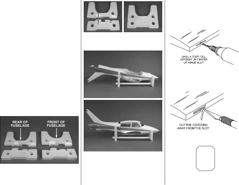
ASSEMBLE THE FUSELAGE STAND
Your kit includes a stand that can be used during the assembly process and as a useful tool for transporting the airplane to the field as well as assembly of the airplane at the field.
1. The stand consists of four foam cradle components and two PVC tubes. There are two different cutouts in the cradle. The curved section fits the front of the fuselage while the one that has the flat cut fits the rear half of the fuselage.
2. The top and bottom stand components will fit snugly together. Fit the bottom with the top cradle (the one with the flat cut) as shown.
3. When placed into the cradle upside down the fuselage is elevated so the tail and the cabin top are off of your work bench. You can also place the fuselage upright in the cradle. If you install the fixed landing gear and wish to transport the fuselage or work on it on your workbench, you will want to place the other bottom cradle component onto the front cradle. This will allow enough clearance for the nose gear.
- 7 -
ASSEMBLE THE WING
Install the Ailerons and Flaps
Assemble the right wing first so your work matches the photos.
1. Drill a 3/32" [2.4mm] hole, 1/2" deep in the center of each hinge slot to allow the CA to “wick” in. Follow-up with a #11 blade to clean out the slots. Hint: If you have one, use a high-speed rotary tool to drill the holes.
2. Use a sharp #11 blade to cut a strip of covering from the hinge slots in the wing and aileron.
3. Cut three 1" x 1" [25mm x25mm] hinges from the CA hinge strip. Snip off the corners so they go in easier.
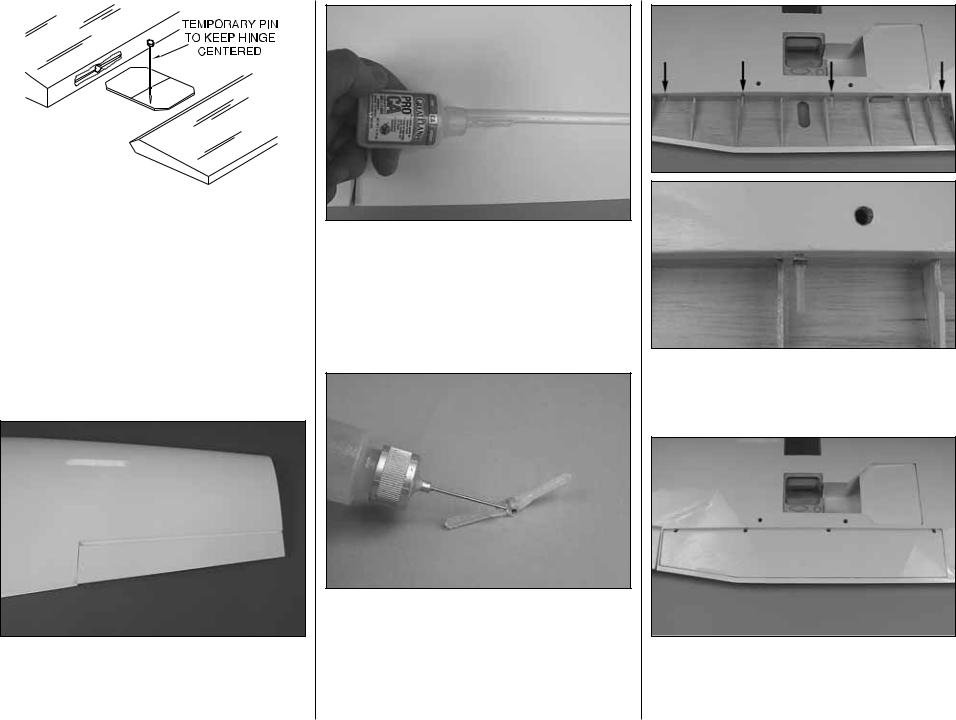
4. Test fit the ailerons to the wing with the hinges. If the hinges don’t remain centered, stick a pin through the middle of the hinge to hold it in position.
5. Remove any pins you may have inserted into the hinges. Adjust the aileron so there is a small gap between the LE of the aileron and the wing. The gap should be small, just enough to see light through or to slip a piece of paper through.
6. Apply six drops of thin CA to the top and bottom of each hinge. Do not use CA accelerator. After the CA has fully hardened, test the hinges by pulling on the aileron.
7. If you have not removed the flap from the wing, do so. Locate four nylon pinned hinges. Apply a drop of oil or work Vaseline into the hinge. This will prevent glue from getting into the hinge in the next step. Be careful not to get oil on the portion of the hinge that slides into the wing and flap. If this should happen be sure to clean the hinge with alcohol before applying the glue.
- 8 -
8. Apply epoxy to one end of each hinge and into each of the four holes in the wing trailing edge in the flap compartment. Insert the hinge into the hole, positioning the hinge as shown.
9. Apply epoxy to the opposite end of the hinge and the hinge holes in the flap. Insert the flap onto the hinges. Set the wing aside until the glue has cured.
10. Repeat steps 1- 9 for the left wing panel.

Mount the Plywood Engine Nacelles
1. Remove the top plate and fuel tank from the plywood engine nacelle. Set the two plywood engine nacelles on your workbench as shown in the photograph. Looking at the top of the nacelle you must note the difference in the angle of the firewall of each nacelle. Each nacelle has 4° of outward thrust built into it. Write the word “left” and “right” on each nacelle so you can easily identify each one.
2. The wing has strings running through it for pulling servo leads through the wing.The string is taped at the root rib, the wing tip and inside the aileron servo compartment. Remove the tape and pull the excess string into the front of the wing where the nacelle will be mounted. Re-tape the end of the string to the rib.
3. Cut the strings. Begin sliding the right nacelle in place and at the same time feed the string through the holes in each side of the nacelle. Re-tie the strings. Apply a drop of thin CA to the knot to prevent it from coming apart.
4. Slide the nacelle completely into the wing. Attach the nacelle to the wing with an 8-32 x 1" [25mm] socket head cap screw, a #8 lock washer and a #8 flat washer. Apply a couple of drops of thread locker onto the bolt before tightening the bolt to the wing and nacelle.
- 9 -
5. Drill 3/32" [2.4mm] holes through each of the two pilot holes located at the back of the nacelle. Drill through the nacelle and into the hardwood block located in the wing. Insert and remove a #6 x 1/2" [13mm] screw into each of the holes. Apply a couple drops of thin CA into the holes to harden the threads. Once the glue has cured install the #6 screws and #6 flat washers into each of the holes.
6. Repeat steps 1- 5 for the left wing panel.
Install Flap, Throttle and Aileron
Servos and Pushrods
1. Install the flap servo into the rear servo opening. Insert and remove a servo mounting screw into each of the pre-drilled holes. Apply a couple drops of thin CA
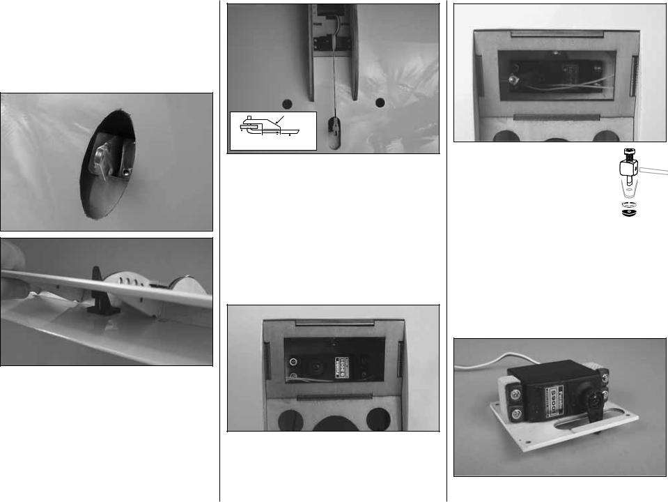
into the holes to harden the threads. Once the glue has cured re-install the servo mounting screws. Be sure the servo lead comes up through the slot alongside of the servo. When installing the flap servo in the right wing panel, the servo arm should be pointed towards the wing tip. When installing the servo in the left wing, the arm should be pointed towards the wing center.
2. Center a black control horn in the opening above the flap, positioning it as shown (the control horn should be backwards from what would be considered the normal direction of a control horn.) Drill a 1/16" [1.6mm] hole through each of the mounting holes in the control horn and into the plywood plate in the flap. Drill only through the plywood plate. DO NOT drill through the flap. Insert and remove a #2 x 3/8" [10mm] screw into each of the holes. Apply a couple drops of thin CA into the holes to harden the threads. Once the glue has cured attach the horn to the flap with four #2 x 3/8" [10mm] screws.
FASLINK
|
|
|
|
|
|
|
|
2-56 (.074") |
|
||
SERVO |
|
||||
HORN |
PUSHROD WIRE |
||||
3. Screw a nylon clevis onto a .074 x 6" [152mm] threaded wire 20 turns. Slide a nylon clevis retainer onto the clevis. Install the clevis into the outermost hole of the control horn. Then slide the silicone retainer over the clevis. Drill a 5/64" [2mm] hole in the outer hole of the servo arm. Position the servo arm as shown and be sure the flap is fully closed. With a fine tip marker, mark the wire where it aligns with the outer hole of the servo arm. Make a 90 degree bend on the mark. Cut the wire so the wire is 3/8" [10mm] in length after the bend. Insert the wire into the servo arm and lock it in place with a nylon Faslink.
4. Install the throttle servo into the servo opening. (Note that the servo is mounted on the bottom of the nacelle). Insert and remove a servo mounting screw into each of the pre-drilled holes. Apply a couple drops of thin CA into the holes to harden the threads. Once the glue has cured, re-install the servo mounting screws.
- 10 -
5. Install a brass screw lock connector, nylon retainer ring and a 4-40 x 1/4" [6mm] socket head cap screw onto the servo arm. Then center the servo and install the arm onto the servo.
6. Install a 6" [152mm] servo extension onto the throttle and flap servo leads. Secure the extension to the lead with tape, a piece of shrink tube or some other method to keep them from coming unplugged.
7. Install a 24" [610mm] servo extension onto the aileron servo lead. Secure the extension to the lead with tape, a piece of shrink tube or some other method to keep them from coming unplugged.
8. Install the aileron servo between the wooden rails under the aileron servo cover using the
hardware that came with the servo. Drill a 1/16" [1.6mm] hole through each of the servo mounting holes and into the servo mounting rails. Insert and remove a servo mounting screw into each of the holes. Apply a couple drops of thin CA into the holes to harden the threads. Once the glue has cured, re-install the servo mounting screws.
9. Center the servo. Then, install a large servo horn to the servo.
10. Tie the string from the servo compartment to the servo lead. Pull the lead through the wing exiting at the nacelle. Leave the string attached to the lead for now.
11. Install the aileron servo cover to the wing with four #2x 3/8"[10mm] wood screws.
12. Look closely under the covering of the aileron and you will see a plywood mounting plate for the control horn. Place a nylon clevis on the plate in line with the servo arm. Mark the location of the mounting holes onto the aileron. Drill a 1/16" [1.6mm] hole on the marks, drilling through the plywood plate but not through the top of the aileron. Insert and remove a #2 x3/8" [10mm] screw into each of the holes. Apply a couple drops of thin CA into the holes to harden the threads. Once the glue has cured, attach the horn to the aileron with two #2 x 3/8" [10mm] screws.
13. Screw a nylon clevis onto a .074 x 6" [152mm] threaded wire 20 turns. Slide a nylon clevis retainer onto the clevis. Install the clevis into the second hole from the end of the control horn. Then slide the silicone retainer over the clevis. Drill a 5/64" [2mm] hole in the outer hole of the servo arm. Center the servo and position the servo arm as shown. Then, center the aileron. With a fine tip marker, mark the wire where it aligns with the outer hole of the servo arm. Make a 90 degree bend on the mark. Cut the wire so the wire is 3/8" [10mm] in length after the bend. Insert the wire into the servo arm and lock it in place with a nylon Faslink.
14. Repeat steps 1- 13 for the left wing panel.
- 11 -
Mount the Wing Tip to the Wing
1. Glue two 1/4" x1/4" x 3/4" [6mm x 6mm x 19mm] balsa triangle blocks onto each side of the slot in the wing.
2. Examine both wing tips to determine which is the left and the right. When installed on the wing the tip should curve upward towards the top of the wing.
3. Pull the wires for the wing tip lights from inside of the wing tip. Tie the end of the wire to the string located on the end of the wing. Pull the wire through the wing exiting at the nacelle. Note: at this point all of the servo leads and the wire for the light should be at the nacelle.
 Loading...