


 Loading...
Top Flite Models Champaign, IL Telephone (217) 398-8970, Ext. 5 airsupport@top-flite.com
WARRANTY |
SPECIFICATIONS |
Top Flite Models guarantees this kit to be free from defects in both material and workmanship at the date of purchase. This warranty does not cover any component parts damaged by use or modification. In no case shall Top Flite’s liability exceed the original cost of the purchased kit. Further, Top Flite reserves the right to change or modify this warranty without notice.
In that Top Flite has no control over the final assembly or material used for final assembly, no liability shall be assumed nor accepted for any damage resulting from the use by the user of the final user-assembled product. By the act of using the user-assembled product, the user accepts all resulting liability.
If the buyer is not prepared to accept the liability associated with the use of this product, the buyer is advised to return this kit immediately in new and unused condition to the place of purchase.
To make a warranty claim send the |
Hobby Services |
defective part or item to Hobby |
3002 N. Apollo Dr. Suite 1 |
Services at this address: |
Champaign IL 61822 USA |
Include a letter stating your name, return shipping address, as much contact information as possible (daytime telephone number, fax number, e-mail address), a detailed description of the problem and a photocopy of the purchase receipt. Upon receipt of the package the problem will be evaluated as quickly as possible.
Wingspan: 63 in
[1600mm]
Wing 730 sq in
Area: [46.5 dm2]
Weight: 9.5 –10.5 lb [3970 – 4540 g]
Wing 30 – 33 oz/sq ft
Loading: [91–101 g/dm2]
Length: 56 in
[1420mm]
Radio: 6+ channel with 8 servos
Engine: .60 –.91 cu in
[10 –15cc] two-stroke,
.90 –1.20 cu in
[15 – 20cc] four-stroke
READ THROUGH THIS MANUAL BEFORE STARTING CONSTRUCTION. IT CONTAINS IMPORTANT INSTRUCTIONS AND WARNINGS CONCERNING THE ASSEMBLY AND USE OF THIS MODEL.
Entire Contents © Copyright 2008 |
Printed in U.S.A. |
TOPA0955Mnl V1.0 |

TABLE OF CONTENTS |
|
|
|
|
PREFLIGHT . . . . . . . . . . . . . . . . . . . 28. . |
. not. . limited. . . . to. flying at contests or on the club field.. It |
||||||||||||||||||
|
|
|
|
|
Identify Your Model . . . . . . . . . |
. . |
. . |
. |
.28. . |
.even. . .applies. |
to flying at public demonstrations and |
|||||||||||||
INTRODUCTION . . . . . . . . . . . . . . . |
. . |
2. . |
Charge the Batteries . . . . . . . . |
. . |
. . |
. |
29. . |
. air. . shows. . .. Failure |
to |
comply with the Safety Code |
||||||||||||||
. . . . . . . |
Propellers . . . . . . . . . |
. . |
. . |
. |
.29. . |
.(excerpts. . . . |
printed |
in |
the back of the manual) may |
|||||||||||||||
AMA . . . . . . . . . . . . . . . . . . . . . |
. |
.2. |
Balance |
|||||||||||||||||||||
. . . . . . . . . . |
. . |
. . |
. |
.29. . |
.endanger. . . . . insurance |
coverage.. Additionally, training |
||||||||||||||||||
SAFETY PRECAUTIONS . . . . . . . . . . . |
. |
.2. |
Ground Check . . . . . . . . . . . |
|||||||||||||||||||||
. . . . . |
|
|
|
|
. . |
. . |
. |
29. . |
. programs. . . . . |
.and instructors are available at AMA club |
||||||||||||||
DECISIONS YOU MUST MAKE . . . . . . . . |
. |
. |
3. |
Range Check . . . . . . . . . . . . |
||||||||||||||||||||
. . . . |
|
|
|
|
. . |
. . |
. |
29. . |
. sites. |
to help you get started the right way.. There are |
||||||||||||||
Radio Equipment . . . . . . . . . . . . . . . |
. 3. |
ENGINE SAFETY PRECAUTIONS . . |
||||||||||||||||||||||
. . . . . . . |
|
|
|
. . |
. . |
. |
.30. . |
.over. . 2,500. . AMA chartered clubs across the country.. |
||||||||||||||||
Engine Recommendations . . . . . . . . . . |
. |
3. . |
AMA SAFETY CODE . . . . . . . . . |
|||||||||||||||||||||
. . . . |
|
|
|
|
. . |
. . |
|
. 30. . |
. Contact. . . . .the. .AMA |
at |
the address or toll-free phone |
|||||||||||||
Landing Gear Options . . . . . . . . . . . |
. |
. |
3. . |
General . . . . . . . . . . . . . . . |
|
|||||||||||||||||||
. . . . . |
|
|
|
|
. . |
. . |
. |
30. . |
. . . . . . . |
|
|
|
|
|
|
|
|
|||||||
|
|
|
|
|
Radio Control . . . . . . . . . . . . |
|
|
|
|
|
|
|
|
|||||||||||
Scale Competition . . . . . . . . . . . . . |
. |
. |
4. . |
. . . . . . |
|
|
|
|
|
|
|
number below: |
|
|
|
|
|
|
|
|||||
|
|
|
. . |
. . |
. |
.30. . |
. . . . . . . |
|
|
|
|
|
|
|
|
|||||||||
ADDITIONAL ITEMS REQUIRED . . . . . . . . |
|
.4. |
CHECK LIST . . . . . . . . . . . . . |
|
|
|
|
|
|
|
|
|||||||||||||
|
. . . |
|
|
|
|
. . |
. . |
|
. 31. . |
. . . . . . . . . |
|
|
|
|
|
|
|
|||||||
|
|
|
|
|
FLYING . . . . . . . . . . . . . . . . . |
|
|
|
|
|
|
|
|
|||||||||||
Hardware and Accessories . . . . . . . . . |
. |
.4. |
. . . . |
|
|
|
|
|
|
|
|
Academy of Model Aeronautics |
||||||||||||
|
|
|
|
. . |
. . |
. |
.31. . |
. . . |
|
|
|
|
|
|
|
|
|
|
||||||
|
|
|
|
|
Fuel Mixture Adjustments . . . . . |
|
|
|
|
|
|
|
|
|
|
|||||||||
Adhesives and Building Supplies . . . . . . . |
. 4. |
|
. . . Takeoff . . . . . . . . . . . . . . . |
|
|
|
|
5151 East Memorial Drive |
||||||||||||||||
|
. . |
. . |
. |
.31. . |
. . . . . . . . |
|
|
|
|
|
|
|
|
|||||||||||
Optional Supplies and Tools . . . . . . . . |
. |
. 4. |
. . . . |
|
|
|
|
|
|
|
|
Muncie, IN 47302-9252 |
||||||||||||
|
|
|
|
. . |
. . |
. |
31. . |
. . . . . . . . |
|
|
|
|
|
|
|
|||||||||
|
|
|
|
|
Flight . . . . . . . . . . . . . . . . |
|
|
|
|
|
|
|
||||||||||||
IMPORTANT BUILDING NOTES . . . . . . . . |
. |
4. . |
. . . |
|
|
|
|
|
|
|
|
Tele.. |
(800) 435-9262 |
|
|
|
|
|
|
|||||
|
|
|
|
. . |
. . |
|
. 32. . |
. . . . . . . . |
|
|
|
|
|
|
|
|
||||||||
|
|
|
|
|
Landing . . . . . . . . . . . . . . . |
|
|
|
|
|
|
|
|
|
||||||||||
KIT INSPECTION . . . . . . . . . . . . . . . |
. |
. |
5. . |
. . . . . . . |
|
|
|
|
|
|
Fax (765) 741-0057 |
|
|
|
|
|
|
|||||||
|
|
|
|
|
|
Or via the Internet at: |
|
|
|
|
|
|
||||||||||||
KIT CONTENTS . . . . . . . . . . . . . . . . . |
. |
5. |
. . . . . . . . |
|
|
|
|
|
|
|
|
|
|
|
||||||||||
|
|
|
|
|
http://www.modelaircraft.org |
|||||||||||||||||||
ORDERING REPLACEMENT PARTS . . . . . |
. |
|
.6. |
. . |
|
|
|
INTRODUCTION |
|
|
|
|
||||||||||||
|
|
|
|
|
|
|
|
|
|
|
|
|
|
|
|
|
|
|
||||||
PREPARATIONS . . . . . . . . . . . . . . . |
. |
. |
6. |
. |
. . . . . . . |
|
|
|
|
|
IMPORTANT!!! Two of the most important things |
|||||||||||||
ASSEMBLE THE WING . . . . . . . . . . . . |
. |
. 6. |
. . . . . . |
|
the great success of the Top Flite P-47 |
|||||||||||||||||||
Mount the Servos . . . . . . . . . . . . . . |
. |
. 6. |
Following |
you can do to preserve the radio controlled aircraft |
||||||||||||||||||||
. . . . . . . |
kit |
comes the same beautiful model in |
hobby are to avoid flying near full-scale aircraft and |
|||||||||||||||||||||
|
|
|
|
|
..60-sized |
|
||||||||||||||||||
Install the Aileron and Flap Pushrods . . . |
. |
. |
8. |
. |
.ARF form! |
|
The sky is the limit for the amount of |
avoid flying near or over groups of people.. |
||||||||||||||||
Join the Wing Panels . . . . . . . . . . . . . |
. 9. |
. . . . . . |
|
|
|
|
|
|
|
|
|
|
|
|
|
|
|
|
|
|
|
|||
Install the Retractable Landing Gear, |
|
|
|
|
additional detail that could be added during the |
|
|
|
|
|
|
|
|
|
|
|
||||||||
|
|
|
|
building process to make the P-47 a model even the |
|
|
|
|
|
|
|
|
|
|
|
|||||||||
Servo, Wheels and Gear Doors . . . . . |
. |
.10. |
. |
.most serious scale-minded builder could appreciate.. |
|
PROTECT YOUR MODEL, |
||||||||||||||||||
Optional Pneumatic Retracts . . . . . . . . |
. |
10. . |
. . . |
|
|
|
|
|
|
|
|
|
||||||||||||
Finish the Wing . . . . . . . . . . . . . . . |
. 14. . |
The model assembles in as little as 15-20 hours, with |
|
YOURSELF & OTHERS... |
||||||||||||||||||||
time consuming painting tasks expertly complete out |
|
|||||||||||||||||||||||
. . . . . . |
|
|
|
|
|
|
|
|
|
|
|
|
|
|
|
|
|
|
|
|||||
ASSEMBLE THE FUSELAGE . . . . . . . . . |
. |
15. . |
. . . |
|
|
|
|
|
|
|
|
|
|
|
|
|
|
|
|
|
|
|
||
Install the Horizontal Stabilizer, |
|
|
|
|
of the box.. |
|
|
|
|
|
|
FOLLOW THESE IMPORTANT |
||||||||||||
|
|
|
|
|
|
|
|
|
|
|
|
|
||||||||||||
|
|
|
|
For the latest technical updates or manual corrections |
|
SAFETY PRECAUTIONS |
||||||||||||||||||
Elevators and Rudder . . . . . . . . . . |
. |
15. . |
. . . . |
|
|
|
|
|
|
|
|
|
|
|
|
|
|
|
|
|
|
|
||
Install the Servos, Engine and Fuel Tank . . |
. |
17. . |
|
to the P-47 ARF, visit the Top Flite web site at www.. |
|
|
|
|
|
|
|
|
|
|
|
|||||||||
Install the Tail Wheel and Linkages . . . . . |
. 19. . |
|
. top-flite..com.. Open the “Airplanes” link, then select |
1..Your P-47 ARF should not be considered a toy, but |
||||||||||||||||||||
Install the Radio System . . . . . . . . . . |
. |
20. . |
. . . . |
|
|
|
|
|
|
|
|
rather a sophisticated, working model that functions |
||||||||||||
FINISH THE MODEL . . . . . . . . . . . . . |
|
|
|
|
the P-47 ARF.. If there is new technical information or |
|
|
|
|
|
|
|
|
|
|
|
||||||||
. |
.22. . |
. . . . . |
|
|
|
|
|
|
|
|
very |
much like a |
full-size airplane.. Because of its |
|||||||||||
|
|
|
|
|
changes to this model, a “tech notice” box will appear |
|
|
|
|
|
|
|
|
|
|
|
||||||||
Install the Cowl & Dummy Engine . . . . . |
. |
.22. |
. |
.in the upper left corner of the page.. |
|
|
|
|
performance capabilities, the P-47, if not assembled |
|||||||||||||||
Install the Scale Details . . . . . . . . . . . |
. 24. . |
. . . . |
|
|
|
|
|
|
|
|
and operated correctly, could possibly cause injury to |
|||||||||||||
Install the Cockpit Interior, Pilot and Canopy |
. |
25. |
|
AMA |
|
|
|
|
|
|
|
|
yourself or spectators and damage to property.. |
|||||||||||
Install the Propeller and Spinner . . . . . . |
. |
26. . |
. . |
|
|
|
|
|
|
|
|
|
|
|
|
|
|
|
|
|
|
|
||
Apply the Decals . . . . . . . . . . . . . . |
. |
27. . |
|
. We. . .urge. . you to join the AMA (Academy of Model |
2.. You must assemble the model according to the |
|||||||||||||||||||
GET THE MODEL READY TO FLY . . . . . . |
. |
27. . |
|
. Aeronautics). |
and a local R/C club.. The AMA is the |
instructions.. Do not alter or modify the model, as |
||||||||||||||||||
Check the Control Directions . . . . . . . . |
. |
27. . |
|
. governing. . |
body of model aviation and membership |
doing so may result in an unsafe or unflyable model.. |
||||||||||||||||||
Set the Control Throws . . . . . . . . . . . |
. 27. . |
|
. is. required. . |
to fly at AMA clubs.. Though joining the |
In a few cases the instructions may differ slightly from |
|||||||||||||||||||
Balance the Model (C..G..) . . . . . . . . . |
. |
.28. |
. |
.AMA. . provides many benefits, one of |
the |
primary |
the photos.. In those instances the written instructions |
|||||||||||||||||
Balance the Model Laterally . . . . . . . . . |
. 28. . |
|
. reasons. . |
to |
join is liability protection.. |
Coverage is |
should be considered as correct.. |
|||||||||||||||||
2
3..You must take time to build straight, true and strong..
4..You must use an R/C radio system that is in firstclass condition, and a correctly sized engine and components (fuel tank, wheels, etc..) throughout the building process..
5..You must correctly install all R/C and other components so that the model operates correctly on the ground and in the air..
6..You must check the operation of the model before every flight to insure that all equipment is operating and that the model has remained structurally sound.. Be sure to check clevises or other connectors often and replace them if they show any signs of wear or fatigue..
7..If you are not an experienced pilot or have not flown this type of model before, we recommend that you get the assistance of an experienced pilot in your R/C club for your first flights.. If you’re not a member of a club, your local hobby shop has information about clubs in your area whose membership includes experienced pilots..
8..While this kit has been flight tested to exceed normal use, if the plane will be used for extremely high stress flying, such as racing, or if an engine larger than one in the recommended range is used, the modeler is responsible for taking steps to reinforce the high stress points and/or substituting hardware more suitable for the increased stress..
We, as the kit manufacturer, provide you with a top quality, thoroughly tested kit and instructions, but ultimately the quality and flyability of your finished model depends on how you build it; therefore, we cannot in any way guarantee the performance of your completed model, and no representations are expressed or implied as to the performance or safety of your completed model..
Remember: Take your time and follow the instructions to end up with a well-built model that is straight and true..
Before starting to build, compare the parts in this model with the Parts List and note any missing parts.. Also inspect all parts to make sure they are of acceptable quality.. If any parts are missing, broken or defective, or if you have any questions about building or flying this airplane, please contact Top Flite at the address or telephone number below.. If requesting replacement parts, please provide the full model name (P-47 ARF) and the part numbers as listed in the Parts List..
Top Flite Product Support
3002 N Apollo Drive Suite 1
Champaign, IL 61822
Telephone: (217) 398-8970
Fax: (217) 398-7721
E-mail: productsupport@top-flite..com
DECISIONS YOU MUST MAKE
This is a partial list of items required to finish the P-47 ARF that may require planning or decision making before starting to build.. Order numbers are provided in parentheses..
RADIO EQUIPMENT
A 6-channel radio system such as a Futaba® 6EXAS with a standard receiver and seven standard size servos with a minimum torque of 50 oz-in [3..6 kg-cm] are required for the control surfaces of the P-47 ARF.. When installing the included mechanical retracts, a 180 degree retract servo will also be required.. If you will be installing optional Robart pneumatic retracts, a micro servo will be required to operate the air valve.. One standard torque servo such as an S3003 is required for the throttle.. Two 24" [610mm] servo extensions (aileron servos), three 6" [152mm] servo extensions (aileron, flap and landing gear) and two Y-harnesses (aileron and flap servos) are also
required.. A receiver battery pack with a minimum capacity of 1000mAh is recommended.. Order numbers are provided below:
oFutaba S9001 Servo Aircraft Coreless BB (FUTM0075)
oFutaba S136G Compact Retract Servo (FUTM0670)
oFutaba S3115 Micro Precision Servo (FUTM0415)
oFutaba S3003 Servo Standard (FUTM0031)
oHobbico® Extension 24" Futaba J (HCAM2200)
oHobbico Extension 6" Futaba J (HCAM2000)
oFutaba 6" Dual Servo Extension J (FUTM4130)
oFutaba NR4RB Receiver NiCd 4..8V 1000mAh J (FUTM1380)
ENGINE RECOMMENDATIONS
A ..60-..91 cu in [10-15cc] two-stroke or ..90-1..20 [1520cc] four-stroke engine is required.. An O..S..® FS-91 Surpass™ II four-stroke engine installation is shown in this manual..
oO..S.. FS-91 II Surpass (OSMG0896)
oO..S.. ..61 FX ABL (OSMG0561)
LANDING GEAR OPTIONS
The P-47 ARF includes mechanical retracts.. Optional pneumatic retracts can also be installed.. Part numbers are provided below:
oRobart 605HD 90 Degree Mains w/3/16" Wire (ROBQ0005)
oRobart 188VR Standard Air Control Kit (ROBQ2302)
oRobart 190 Air Line Quick Disconnects (ROBQ2395)
SCALE COMPETITION
Though the Top Flite P-47 ARF may not have the same level of detail as an “all-out” scratch-built competition model, it is a scale model nonetheless and is therefore eligible to compete in the Fun Scale class in AMA competition (we receive many favorable reports of Top Flite models in scale competition!)..
3
To receive the five points for scale documentation, the only proof required that a full size aircraft of this type in your paint/markings scheme did exist is a single sheet such as a kit box cover from a plastic model, a photo, or a profile painting, etc.. If the photo is in black and white other written documentation of color must be provided.. Contact the AMA for a rule book with full details..
If you would like photos of the full-size P-47 for scale documentation, or if you would like to study the photos to add more scale details, photo packs are available from:
Bob’s Aircraft |
Phone: (714) 979-8058 |
Documentation |
Fax: (714) 979-7279 |
3114 Yukon Ave |
|
Costa Mesa, CA 92626 |
www..bobsairdoc..com |
ADDITIONAL ITEMS REQUIRED
HARDWARE AND ACCESSORIES
In addition to the items listed in the “Decisions You Must Make” section, following is the list of hardware and accessories required to finish the P-47 ARF.. Order numbers are provided in parentheses..
oR/C foam rubber (1/4" [6mm] - HCAQ1000, or 1/2" [13mm] - HCAQ1050)
o3' [900mm] standard silicone fuel tubing (GPMQ4131)
ADHESIVES AND BUILDING SUPPLIES
In addition to common household tools (screw drivers, drill, etc..), this is the “short list” of the most important items required to build the P-47 ARF.. We recommend
Great Planes Pro™ CA and Epoxy glue.
o1/2 oz.. [15g] Thin Pro CA (GPMR6001)
o1/2 oz.. [15g] Medium Pro CA+ (GPMR6007)
oPro 6-minute epoxy (GPMR6045)
oPro 30-minute epoxy (GPMR6047)
oDrill bits: 1/16" [1..6mm], 5/64" [2mm], 3/32" [2..4mm], 3/16" [4..8mm]
o8-32 tap and drill set (GPMR8103)
oGreat Planes Pro Threadlocker (GPMR6060)
o#1 Hobby knife (HCAR0105)
o#11 blades (5-pack, HCAR0211)
oMedium T-pins (100, HCAR5150)
oMasking tape (TOPR8018)
oDenatured alcohol (for epoxy clean up)
oPanel Line Pen (TOPQ2510)
o220-grit sandpaper
oPetroleum jelly or oil
o4 oz.. J&Z R/C-56 Glue (JOZR5007)
OPTIONAL SUPPLIES AND TOOLS
Here is a list of optional tools mentioned in the manual that will help you build the P-47 ARF..
o21st Century® sealing iron (COVR2700)
o21st Century iron cover (COVR2702)
o21st Century trim seal iron (COVR2750)
o1/2 oz.. [15g] Thick Pro CA- (GPMR6013)
oSmall metal file
oStick-on segmented lead weights (GPMQ4485)
o2 oz.. [57g] spray CA activator (GPMR6035)
o4 oz.. [113g] aerosol CA activator (GPMR6034)
oCA applicator tips (HCAR3780)
oCA debonder (GPMR6039)
oEpoxy brushes 6, (GPMR8060)
oMixing sticks (GPMR8055)
oMixing cups (GPMR8056)
oPliers with wire cutter (HCAR0630)
oCompressed Air 10 oz (TAEC1060)
oMicroballoons (TOPR1090)
oErnst Charge Receptacle Futaba J (ERNM3001)
oRotary tool such as Dremel
oRotary tool reinforced cut-off wheel (GPMR8020)
oServo horn drill (HCAR0698)
oHobby Heat™ micro torch (HCAR0750)
oDead Center™ Engine Mount Hole Locator (GPMR8130)
oAccuThrow™ Deflection Gauge (GPMR2405)
oCG Machine™ (GPMR2400)
oPrecision Magnetic Prop Balancer (TOPQ5700)
oHobbico Flexible 18" Ruler Stainless Steel (HCAR0460)
oHobbico Pin Vise 1/16 Collet w/6 Bits (HCAR0696)
oHobbico 8-Piece Ball Tip Hex L Wrench SAE (HCAR0520)
oHobbico 7-Piece Ball Tip Hex L Wrench Metric (HCAR0521)
oGreat Planes Precision Prop Reamer Standard (GPMQ5006)
oGreat Planes Precision Prop Reamer Metric (GPMQ5007)
oGreat Planes Clevis Installation Tool (GPMR8030)
oX-Acto Extra Hands Double Clip (XACR4214)
IMPORTANT BUILDING NOTES
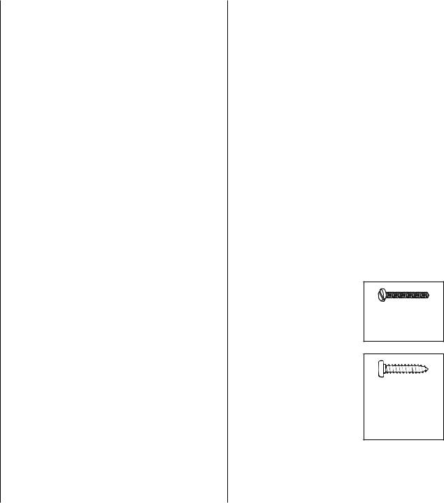
• There are two types of screws used in this kit:
Sheet metal screws are designated by a number and a length. For example #6 x 3/4" [19mm].
Machine screws are designated by a number, threads per inch, and a length. For example 4-40 x 3/4" [19mm].
This is a number six screw that is 3/4" [19mm] long.
This is a number four screw that is 3/4" [19mm] long with forty threads per inch.
• When you see the term test fit in the instructions, it means that you should first position the part on the assembly without using any glue, then slightly modify or custom fit the part as necessary for the best fit..
4
•Whenever the term glue is written you should rely upon your experience to decide what type of glue to use.. When a specific type of adhesive works best for that step, the instructions will make a recommendation..
•Whenever just epoxy is specified you may use either 30-minute (or 45-minute) epoxy or 6-minute epoxy.. When 30-minute epoxy is specified it is highly
recommended that you use only 30-minute (or 45-minute) epoxy, because you will need the working time and/or the additional strength..
• Photos and sketches are placed before the step they refer to.. Frequently you can study photos in following steps to get another view of the same parts..
KIT INSPECTION
Before starting to build, take an inventory of this kit to make sure it is complete, and inspect the parts to make sure they are of acceptable quality.. If any parts are missing or are not of acceptable quality, or if you need assistance with assembly, contact Product Support.. When reporting defective or missing parts, use the part names exactly as they are written in the Kit Contents list..
Top Flite Product Support
3002 N Apollo Drive, Suite 1
Champaign, IL 61822
Telephone: (217) 398-8970, ext.. 5
Fax: (217) 398-7721
E-mail: airsupport@top-flite..com
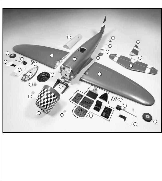
KIT CONTENTS
|
|
6 |
|
|
14 |
|
|
|
|
|
4 |
|
|
|
|
|
15 |
10 |
|
|
|
|
16 |
|
2 |
|
|
|
|
|
|
|
17 |
21 |
|
9 |
|
|
1 |
||
|
|
|
|
||
11 |
22 |
|
|
|
|
|
|
|
|
3 |
|
|
|
|
|
|
|
12 |
|
|
|
|
|
7 |
|
13 |
|
2 |
|
19 |
|
20 |
|
|
|
|
|
|
|
|
|
18 |
|
|
|
|
22 |
|
|
|
|
|
|
|
|
|
|
|
9 |
|
5 |
18 |
|
8 |
|
|
|
|
|
10
11
1 |
- Fuselage |
9 |
- Retractable landing gear and axle |
17 |
- Side scoops |
2 |
- Left and right wing panel |
10 |
- Wheels |
18 |
- Forward scoops |
3 |
- Stabilizer with left and right elevator |
11 |
- Landing gear doors |
19 |
- Spinner |
4 |
- Rudder |
12 |
- Fuel tank |
20 |
- Engine mount |
5 |
- Cowl |
13 |
- Dummy engine |
21 |
- Elevator joiner wire |
6 |
- Belly pan |
14 |
- Tail wheel |
22 |
- Machine guns |
7 |
- Canopy |
15 |
- Tail wheel cover |
|
|
8 |
- Cockpit components |
16 |
- Lower scoop |
|
|
5

ORDERING
REPLACEMENT PARTS
Replacement parts for the Top Flite P-47 ARF are available using the order numbers in the Replacement Parts List that follows.. The fastest, most economical service can be provided by your hobby dealer or mailorder company..
To locate a hobby dealer, visit the Hobbico web site at www..hobbico..com.. Choose “Where to Buy” at the bottom of the menu on the left side of the page.. Follow the instructions provided on the page to locate a U..S.., Canadian or International dealer.. If a hobby shop is not available, replacement parts may also be ordered from Tower Hobbies® at www..towerhobbies.. com, or by calling toll free (800) 637-6050..
Parts may also be ordered directly from Hobby Services by calling (217) 398-0007, or via facsimile at (217) 398-7721, but full retail prices and shipping and handling charges will apply.. Illinois and Nevada residents will also be charged sales tax.. If ordering via fax, include a Visa® or MasterCard® number and expiration date for payment..
Mail parts orders and payments by personal check to:
Hobby Services
3002 N Apollo Dr.., Suite 1 Champaign IL 61822
Be certain to specify the order number exactly as listed in the Replacement Parts List.. Payment by credit card or personal check only; no C..O..D..
If additional assistance is required for any reason contact Product Support by e-mail at
productsupport@top-flite..com,
or by telephone at (217) 398-8970..
REPLACEMENT PARTS LIST
Order |
Description |
How to |
|
Number |
purchase |
||
|
|||
|
|
|
|
|
Missing pieces |
Contact |
|
|
|
Product |
|
|
|
||
|
Instruction manual |
Support |
|
|
|
|
|
|
Full-size plans |
Not available |
|
|
|
|
|
TOPA1782 |
Wing Set |
|
|
T/F P-47 ARF |
|
||
|
|
||
|
|
|
|
TOPA1783 |
Fuselage |
|
|
T/F P-47 ARF |
|
||
|
|
||
|
|
|
|
TOPA1784 |
Tail Set |
|
|
T/F P-47 ARF |
|
||
|
|
||
|
|
|
|
TOPA1785 |
Cowl |
|
|
T/F P-47 ARF |
|
||
|
|
||
|
|
|
|
TOPA1786 |
Canopy |
Contact |
|
T/F P-47 ARF |
|||
|
your |
||
|
|
||
TOPA1787 |
Decals |
hobby |
|
T/F P-47 ARF |
supplier |
||
|
|||
|
|
to |
|
|
Dummy Engine |
||
TOPA1788 |
purchase |
||
T/F P-47 ARF |
these |
||
|
|||
|
|
items |
|
|
Wire Landing |
||
|
|
||
TOPA1789 |
Gear Set |
|
|
|
T/F P-47 ARF |
|
|
|
|
|
|
TOPA1790 |
Spinner |
|
|
T/F P-47 ARF |
|
||
|
|
||
|
|
|
|
TOPA1791 |
Gear Doors |
|
|
T/F P-47 ARF |
|
||
|
|
||
|
|
|
|
TOPA1792 |
Belly Pan |
|
|
T/F P-47 ARF |
|
||
|
|
||
|
|
|
PREPARATIONS
o 1.. If you have not done so already, remove the major parts of the kit from the box and inspect for damage.. If any parts are damaged or missing, contact Product Support at the address or telephone number listed in the Kit Inspection section on page 5..
o 2.. Use a covering iron with a covering sock on high heat to tighten the covering if necessary.. Apply pressure over sheeted areas to thoroughly bond the covering to the wood..
ASSEMBLE THE WING
MOUNT THE SERVOS
Before completing this section, confirm that the servos that you will be using will properly fit between the servo mounting block locations on the aileron and flap servo hatch covers. Make adjustments as necessary for your brand of servos. The block locations shown in this section will fit a standard size Futaba brand servo.
6

o o 1.. Remove the tape holding the aileron and flap covers to the wing.. The servo mounting blocks are pre-attached to the covers.. To assure the blocks have been adequately glued, apply a few drops of thin CA to each of the blocks..
o o 2.. Cut three arms from a four-armed servo arm included with the aileron servo.. Enlarge the outer hole of the remaining arm with a 5/64" [2mm] drill bit..
o o 3.. Attach a 24" [610mm] servo extension to each aileron servo and secure the connector using tape or heat shrink tubing (not included).. Center the servos with your radio system and install the servo arm to the servo perpendicular to the servo case as shown.. Be sure to reinstall the servo arm screw into the servo..
o o 4.. Position the servo against the underside of the aileron servo hatch cover between the mounting blocks..Drill 1/16" [1..6mm] holes through the mounting tabs on the servo case into the blocks.. Insert and then remove a servo mounting screw (included with the servo) into each hole.. Apply a drop of thin CA
to each hole to harden the wood.. When the CA has dried, install the servo onto the hatch cover using the hardware supplied with the servo..
o o 5.. Tie the string taped inside the aileron servo hatches to the servo lead.. The opposite end of the string is taped to the wing's root rib.. Pull the servo lead through the wing ribs..
o o 6.. Insert and then remove a #2 x 3/8" [9..5mm] self-tapping screw into each hatch mounting hole.. Apply a drop of thin CA to each hole to harden the wood.. Once the glue has dried, install the aileron hatch cover to the wing as shown using four #2 x 3/8" [9..5mm] self-tapping screws and four #2 flat washers..
7
o o 7.. Mount the flap servo and hatch cover in the same way.. The flap servo does not require a servo lead extension..
o o 8.. Insert the servo leads through the hole in the top of the wing.. Tape the leads to the wing to prevent them from dropping back in..
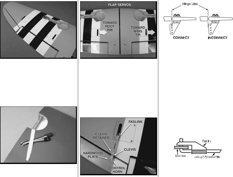
o 9.. Repeat steps 1-9 for the left wing panel.. Make note that the flap servo arm will be mounted on the root rib side of the right wing panel and the flap servo arm is mounted towards the wing tip on the left wing panel.. When the flap servos are joined together using a Y-harness, they will both move in the same direction..
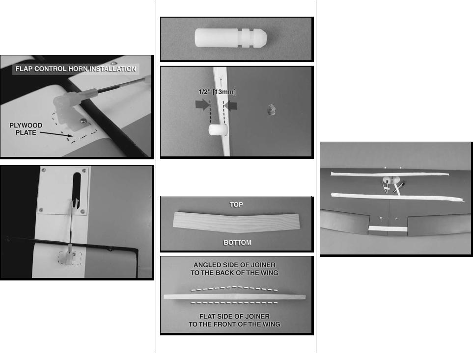
INSTALL THE AILERON
AND FLAP PUSHRODS
Refer to the photograph as you complete steps 1-4..
o o 1..Thread a nylon clevis 20 complete turns onto a 4" [152mm] pushrod.. Slide a silicone clevis retainer onto the clevis and connect the clevis to the outer hole of a nylon control horn..
o o 2.. Position the control horn over the plywood plate in the aileron (if you cannot see it, hold the aileron at a shallow angle in good lighting or use a small pin to puncture the covering) using the position of the servo arm as a guide.. Align the holes in the control horn directly over the aileron hinge line and mark the location of the control horn mounting holes..
o o 3.. Drill 1/16" [1..6mm] holes at the marks you made through the plywood plate.. Do not drill all the way through the aileron! Thread a #2 x 3/8" [9..5mm] self-tapping screw through each hole and back it out.. Apply a couple drops of thin CA glue to each hole to harden the wood.. When the glue has dried, install the control horns onto the aileron using two #2 x 3/8" [9..5mm] self-tapping screws..
o o 4.. Use tape or a small clamp to hold the aileron in the neutral position.. Make a mark on the pushrod where it crosses the outer hole in the servo arm.. Make a 90 degree bend at the mark on the pushrod
8
and cut off the excess pushrod 1/4" [6mm] beyond the bend.. Attach the pushrod to the servo arm using a nylon FasLink.. Thread the clevis up or down on the pushrod as necessary to center the aileron with the servo arm centered.. Slide the silicone clevis retainer to the end of the clevis to secure it..
o o 5.. Install the flap pushrod using the same procedure used for the aileron.. The flap pushrod is installed in the same manner except the control horn is mounted as shown in the photograph, and rather than centering the servo arm, position the servo arm so that it is angled back towards the trailing edge of the wing..
o 6.. Repeat steps 1-5 for the other wing panel..
JOIN THE WING PANELS
o 1.. Locate the nylon anti-rotation pin.. Epoxy it into the hole in the right wing panel.. Approximately ½"[13mm] of the pin should extend from the wing
o 2.. Locate the hardwood wing joiner.. The joiner has a double taper.. The photo shows how to identify
the top of the joiner and the front of the joiner.. Test fit the joiner into the joiner pocket of each wing panel.. The joiner should be able to fit halfway into each pocket and be slightly loose to allow room for epoxy.. Sand the joiner as necessary for the proper fit..
o 3.. Dry fit the wing panels together using the joiner.. The root ribs of the panels should sit flat against each other with no gaps.. Lightly sand the face of the root ribs if necessary to eliminate any gaps between the wing panels..
o 4.. When satisfied with the fit of the wing panels mix up a ½ ounce of 30-minute epoxy and coat the inside of the wing joiner pockets in each wing panel.. Coat one half of the wing joiner and slide it into one wing panel.. Coat the root ribs of both wing panels as well as the exposed ends of the joiner and antirotation pin.. Join the two wing panels together and use paper towels dampened with denatured alcohol to wipe away any excess epoxy from the joint between the panels.. Use masking tape to hold the panels together tightly.. Set the wing aside and let the epoxy cure undisturbed..
9
o 5.. Glue two nylon pins into the holes in the leading edge, at the center of the wing.. Approximately ½"[13mm] should extend from the leading edge of the wing..
INSTALL THE RETRACTABLE LANDING GEAR, SERVO, WHEELS AND GEAR DOORS
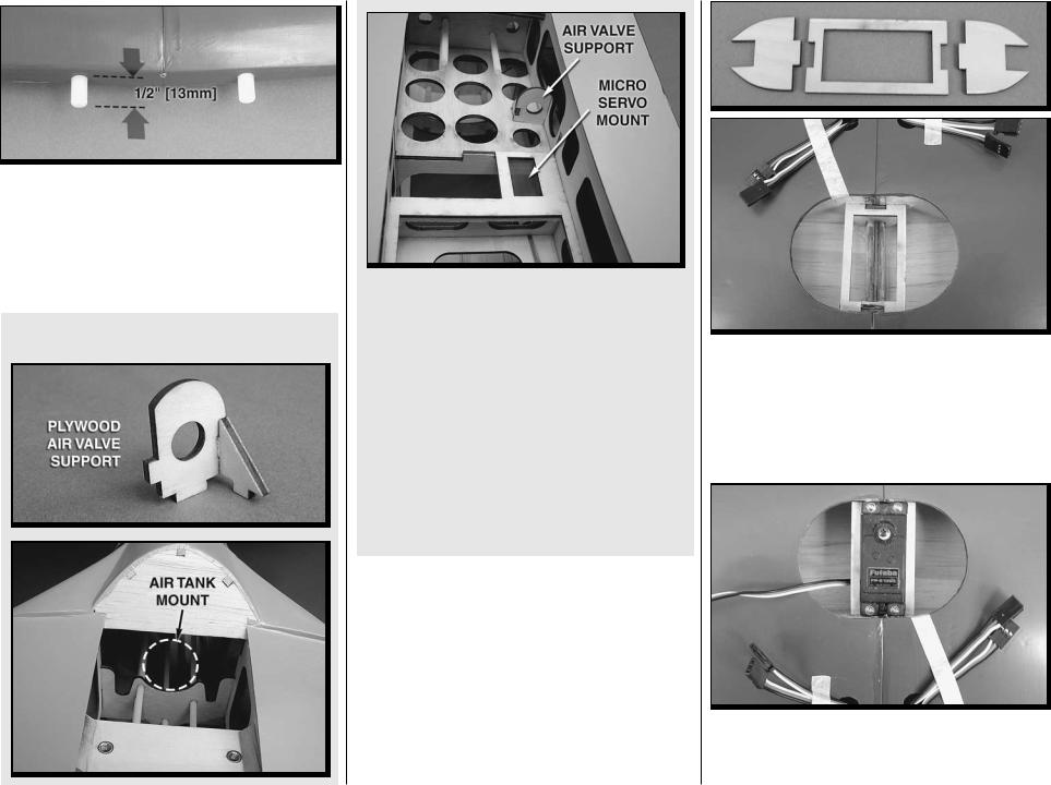
Optional Pneumatic Retracts
Some modelers may wish to install pneumatic retractsinsteadofthemechanicalretractsincluded in this kit.. Mounting locations are provided in the fuselage for optional pneumatic retract hardware including the air tank, air valve, and air valve servo.. Tabs are designed into the air tank that support the front of the air tank for securing it with rubber bands.. Detailed installation instructions are not provided for installing pneumatic retracts.. However, the installation process for the gear is similar to the mechanical installation shown in the following instructions.. The mechanical retract pushrods will need to be replaced with air lines.. Be sure to follow the instructions included with the pneumatic retract kit..
10
o 1.. Locate the 3 plywood parts that make up the servo tray.. Test fit them into the center of the wing.. Adjust the parts as needed.. Once you are satisfied with the fit, glue the components in place..You will find it easiest to glue each of the components in place individually rather than gluing it together and then trying to fit it into the opening..
2.. Install your retract servo between the mounting rail in the wing center section using the hardware that came with the servo.. Be sure to harden the screw holes with thin CA glue..
o o 3.. Remove the set screw from each side of the landing gear.. Apply a couple of drops of thread locker onto the set screws.. Then re-insert it and tighten it against the landing gear wire.. Do this for both gear..
o o 4.. Position the landing gear onto the landing gear rails as shown here.. With a pencil or fine tip marker, mark the location of the holes for mounting the landing gear..
o o 5.. On the marks you made for the location of the landing gear drill a 7/64" [2..8mm] hole through the rails.. Insert and remove a #6 x3/4" [19mm] screw into each of the holes.. Apply a couple drops of thin CA into the holes to harden the threads.. Allow the glue to harden..
o o 6.. Locate one of the 12" [305mm] wires with the “Z” bend on the end.. Insert the end with the “Z” bend into the connector on the end of the retract unit..
o o 7.. Insert the wire from the landing gear into the tube located in the wheel well.. Using the tube as a guide, push the wire into the wing until the landing gear can rest on the landing gear rails..
o o 8.. Mount the landing gear to the rail with four #6 x ¾" [19mm] screws and four #6 flat washers..
o o 9.. Apply a drop of thread locker to two 3mm set screws.. Then, thread them into the axle (the set screws may already be installed in the axle.. If so remove them, apply thread locker, and then re-install them into the axle).. Slide the axle onto the landing gear..Tighten the set screws in the axle against the flat spots that have been cut into the end of the landing gear.. When the axle is properly installed, the end of the axle will fit into the wheel well as shown..
11
Loading...