


WARRANTY
Top Flite Models guarantees this kit to be free from defects in both material and workmanship at the date of purchase. This warranty does not cover any component parts damaged by use or modification. In no case shall Top Flite’s liability exceed the original cost of the purchased kit. Further, Top Flite reserves the right to change or modify this warranty without notice.
In that Top Flite has no control over the final assembly or material used for final assembly, no liability shall be assumed nor accepted for any damage resulting from the use by the user of the final user-assembled product. By the act of using the user-assembled product, the user accepts all resulting liability.
If the buyer is not prepared to accept the liability associated with the use of this product, the buyer is advised to return this kit immediately in new and unused condition to the place of purchase.
To make a warranty claim send the |
Hobby Services |
defective part or item to Hobby |
3002 N. Apollo Dr. Suite 1 |
Services at this address: |
Champaign IL 61822 USA |
Include a letter stating your name, return shipping address, as much contact information as possible (daytime telephone number, fax number, e-mail address), a detailed description of the problem and a photocopy of the purchase receipt. Upon receipt of the package the problem will be evaluated as quickly as possible.
Top Flite Models Champaign, IL Ph: (217) 398-8970, Ext. 5 Fax: (217) 398-7721 airsupport@top-flite.com
SPECIFICATIONS
Wingspan: 64.5 in [1640mm]
Wing Area: 722 sq in [46.6 dm2]
Weight: 9.75– 10 lb [4420– 4530 g]
Wing 31– 32 oz/sq ft
Loading: [95–98 g/dm2]
Length: 55 in
[1395mm]
Radio: 5-6 channel with 7-8 servos
Engine: .60–.91 cu in [10–15cc] two-stroke,
.90–1.20 cu in [15–20cc] four-stroke
READ THROUGH THIS MANUAL BEFORE STARTING CONSTRUCTION. IT CONTAINS IMPORTANT INSTRUCTIONS AND WARNINGS CONCERNING THE ASSEMBLY AND USE OF THIS MODEL.
Entire Contents © 2010 Hobbico®, Inc. |
TOPA0970 Mnl |

TABLE OF CONTENTS |
|
INTRODUCTION |
|||||||||
INTRODUCTION |
2 |
|
FINISH THE MODEL |
22 |
TopFlite is well known for the quality and scale detail |
||||||
|
|||||||||||
AMA |
2 |
|
Install the Cowl and Spinner |
22 |
provided with our kits. Now you can have that same |
||||||
|
quality and detail in an ARF that can be completed in |
||||||||||
SAFETY PRECAUTIONS . . . . . . . . . . . . . . . . . . . |
. 3 |
|
Install the Cockpit Kit and Canopy . . . . . . . . . . . |
24 |
|||||||
DECISIONS YOU MUST MAKE. . . . . . . . . . . . . . . |
. 3 |
|
Optional Pneumatic Retract |
|
as little as 15-20 hours! Beautifully covered in TopFlite |
||||||
Building Stand |
3 |
|
Hardware Installation |
25 |
MonoKote® with expertly painted fi berglass parts, the |
||||||
|
P-40 Warhawk will surely be the focus of attention |
||||||||||
Radio Equipment . . . . . . . . . . . . . . . . . . . . . . . . |
. 3 |
|
APPLY THE DECALS . . . . . . . . . . . . . . . . . . . . . . |
27 |
|||||||
Engine Recommendations . . . . . . . . . . . . . . . . . |
. 4 |
|
GET THE MODEL READY TO FLY . . . . . . . . . . . . |
27 |
at the fl ying fi eld. In |
addition, the P-40 includes |
|||||
Landing Gear Options |
4 |
|
Check the Control Directions |
27 |
economical fi xed landing gear, but is designed so that |
||||||
|
the optional pneumatic retract set made specifi cally |
||||||||||
Scale Competition |
4 |
|
Set the Control Throws |
27 |
|||||||
|
for TopFlite warbirds is a drop in installation. |
||||||||||
ADDITIONAL ITEMS REQUIRED . . . . . . . . . . . . . |
. 4 |
|
Balance the Model (C.G.). . . . . . . . . . . . . . . . . . |
28 |
|||||||
Hardware and Accessories . . . . . . . . . . . . . . . . |
. 4 |
|
Balance the Model Laterally. . . . . . . . . . . . . . . . |
28 |
For the latest technical updates or manual corrections |
||||||
Adhesives and Building Supplies . . . . . . . . . . . . |
. 4 |
|
PREFLIGHT . . . . . . . . . . . . . . . . . . . . . . . . . . . . . . |
28 |
|||||||
Optional Supplies and Tools. . . . . . . . . . . . . . . . |
. 4 |
|
Identify Your Model . . . . . . . . . . . . . . . . . . . . . . . |
28 |
to the P-40 Warhawk ARF visit the Top Flite web site |
||||||
IMPORTANT BUILDING NOTES. . . . . . . . . . . . . . |
. 5 |
|
Charge the Batteries . . . . . . . . . . . . . . . . . . . . . |
28 |
at www.top-fl ite.com. Open the “Airplanes” link, then |
||||||
KIT INSPECTION. . . . . . . . . . . . . . . . . . . . . . . . . . |
. 5 |
|
Balance Propellers . . . . . . . . . . . . . . . . . . . . . . . |
29 |
select the P-40 Warhawk ARF. If there is new technical |
||||||
ORDERING REPLACEMENT PARTS . . . . . . . . . . |
. 5 |
|
Ground Check . . . . . . . . . . . . . . . . . . . . . . . . . . |
29 |
information or changes to this model a “tech notice” |
||||||
COMMON ABBREVIATIONS . . . . . . . . . . . . . . . . |
. 6 |
|
Range Check . . . . . . . . . . . . . . . . . . . . . . . . . . . |
29 |
box will appear in the upper left corner of the page. |
||||||
KIT CONTENTS. . . . . . . . . . . . . . . . . . . . . . . . . . . |
. 6 |
|
ENGINE SAFETY PRECAUTIONS . . . . . . . . . . . . |
29 |
AMA |
|
|
|
|
|
|
PREPARATIONS |
7 |
|
AMA SAFETY CODE (excerpts) |
29 |
|
|
|
|
|
|
|
|
|
|
|
|
|
|
|
||||
ASSEMBLE THE WING . . . . . . . . . . . . . . . . . . . . . |
. 7 |
|
General . . . . . . . . . . . . . . . . . . . . . . . . . . . . . . . |
29 |
We urge you to join the AMA (Academy of Model |
||||||
Hinge the Ailerons & Flaps |
7 |
|
Radio Control |
30 |
|||||||
|
Aeronautics) and a local R/C club. The AMA is the |
||||||||||
Mount the Servos |
9 |
|
CHECK LIST |
30 |
|||||||
|
governing body of model aviation and membership is |
||||||||||
Install the Aileron and Flap Pushrods |
11 |
|
FLYING |
30 |
|||||||
|
required to fl y at AMA clubs. Though joining the AMA |
||||||||||
Finish the Wing |
12 |
|
Fuel Mixture Adjustments |
30 |
|||||||
|
provides many benefi ts, one of the primary reasons |
||||||||||
Optional Pneumatic Retract Installation |
14 |
|
Takeoff |
31 |
|||||||
|
to join is liability protection. Coverage is not limited to |
||||||||||
ASSEMBLE THE TAIL SECTION |
16 |
|
Flight |
31 |
|||||||
|
fl ying at contests or on the club fi eld. It even applies to |
||||||||||
INSTALL THE ENGINE AND FUEL TANK |
18 |
|
Landing |
31 |
|||||||
|
fl ying at public demonstrations and air shows. Failure |
||||||||||
INSTALL THE RADIO SYSTEM |
20 |
|
|
|
|||||||
|
|
|
to comply with the Safety Code (excerpts printed in the |
||||||||
|
|
|
|
|
|||||||
|
|
|
|
|
back of the manual) may endanger insurance coverage. |
||||||
|
|
|
|
|
Additionally, training programs and instructors are |
||||||
|
|
|
|
|
available at AMA club sites to help you get started the |
||||||
|
|
|
|
|
right way. There are over 2,500 AMA chartered clubs |
||||||
|
|
|
|
|
across the country. Contact the AMA at the address or |
||||||
|
|
|
|
|
toll-free phone number below: |
||||||
|
|
|
|
|
Academy of Model Aeronautics |
||||||
|
|
|
|
|
5151 East Memorial Drive |
||||||
|
|
|
|
|
Muncie, IN 47302-9252 |
|
|
|
|
|
|
|
|
|
|
|
Ph. (800) 435-9262 |
Or via the Internet at: |
|||||
|
|
|
|
|
Fax (765) 741-0057 |
http://www.modelaircraft.org |
|||||
|
|
|
|
|
|
|
|
|
|
|
|
2
IMPORTANT!!! Two of the most important things you can do to preserve the radio controlled aircraft hobby are to avoid fl ying near full-scale aircraft and avoid fl ying near or over groups of people.
PROTECT YOUR MODEL, YOURSELF & OTHERS… FOLLOW THESE IMPORTANT SAFETY PRECAUTIONS
1. Your P-40 Warhawk ARF should not be considered a toy, but rather a sophisticated, working model that functions very much like a full-size airplane.Because of its performance capabilities, the P-40, if not assembled and operated correctly, could possibly cause injury to yourself or spectators and damage to property.
2.You must assemble the model according to the instructions. Do not alter or modify the model, as doing so may result in an unsafe or unfl yable model. In a few cases the instructions may differ slightly from the photos. In those instances the written instructions should be considered as correct.
3.You must take time to build straight, true and strong.
4.You must use an R/C radio system that is in fi rstclass condition, and a correctly sized engine and components (fuel tank, wheels, etc.) throughout the building process.
5.You must correctly install all R/C and other components so that the model operates correctly on the ground and in the air.
6.You must check the operation of the model before every flight to insure that all equipment is operating and that the model has remained structurally sound. Be sure to check clevises or other connectors often and replace them if they show any signs of wear or fatigue.
7.If you are not an experienced pilot or have not fl own this type of model before, we recommend that you get the assistance of an experienced pilot in your
R/C club for your fi rst fl ights. If you’re not a member of a club, your local hobby shop has information about clubs in your area whose membership includes experienced pilots.
8. While this kit has been fl ight tested to exceed normal use, if the plane will be used for extremely high stress fl ying, such as racing, or if an engine larger than one in the recommended range is used, the modeler is responsible for taking steps to reinforce the high stress points and/or substituting hardware more suitable for the increased stress.
We, as the kit manufacturer, provide you with a top quality, thoroughly tested kit and instructions, but ultimately the quality and fl yability of your fi nished model depends on how you build it; therefore, we cannot in any way guarantee the performance of your completed model, and no representations are expressed or implied as to the performance or safety of your completed model.
Remember: Take your time and follow the instructions to end up with a well-built model that is straight and true.
Before starting to build, compare the parts in this model with the Parts List and note any missing parts. Also inspect all parts to make sure they are of acceptable quality. If any parts are missing, broken or defective, or if you have any questions about building or fl ying this airplane, please contact Top Flite at the address or telephone number below. If requesting replacement parts, please provide the full model name (P-40 Warhawk ARF) and the part numbers as listed in the Parts List.
Top Flite Product Support |
|
3002 N Apollo Drive, Suite 1 |
Ph: (217) 398-8970 |
Champaign, IL 61822 |
Fax: (217) 398-7721 |
E-mail: productsupport@top-fl ite.com
DECISIONS YOU MUST MAKE
This is a partial list of items required to fi nish the P-40 Warhawk ARF that may require planning or decision making before starting to build. Order numbers are provided in parentheses.
BUILDING STAND
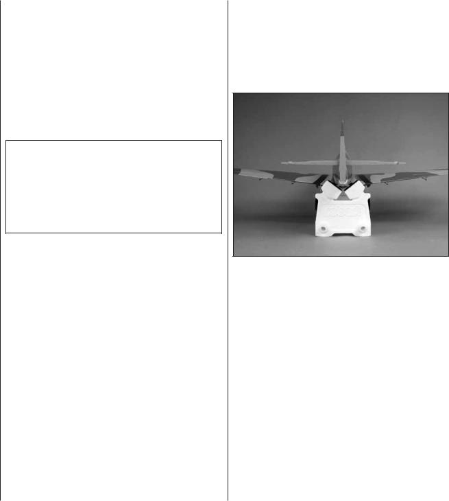
A building stand or cradle comes in very handy during the build. We use the Robart Super Stand II (ROBP1402) for most of our projects in R&D, and it can be seen in pictures throughout this manual.
RADIO EQUIPMENT
A minimum 5-channel radio system with a standard receiver and seven standard size servos with a minimum torque of 50 oz-in [3.6 kg-cm] are required for the control surfaces of the P-40 Warhawk ARF. If installing optional pneumatic retracts, a standard torque servo such as a Futaba S3003 will also be required. One standard torque servo is required for the throttle. A receiver battery pack with a minimum capacity of 1000mAh is recommended.Order numbers are provided below:
Futaba® S9001 Servo Aircraft Coreless BB (FUTM0075)
Futaba S3003 Servo Standard (FUTM0031)
3

Futaba NR4RB Receiver NiCd 4.8V |
1000mAh J (FUTM1380) |
OR |
Hobbico® HydriMax™ 4-Cell 4.8V 2000mAh |
NiMH Flat AA Rx U (HCAM6321) |
If you have a radio system with enough available channels to mix the fl ap and aileron servos together, then you will need two 16" [406mm] servo extensions to connect the aileron servos directly to the receiver and you will need two 12" [305mm] servo extensions to connect the fl ap servos directly to the receiver:
Futaba Servo Extension 16" J (FUTM3955)
Hobbico Extension 12" Futaba J (HCAM2100)
If you plan to connect the aileron and fl ap servos together using Y-harnesses then you will need two 12" [305mm] servo extensions for the ailerons and two 6" [152mm] servo extensions for the fl ap servos. You will also need two Y-harnesses:
Hobbico Extension 12" Futaba J (HCAM2100)
Hobbico Extension 6" Futaba J (HCAM2000)
Futaba 6" Dual Servo Extension J (FUTM4130)
ENGINE RECOMMENDATIONS
A .60-.91 cu in [10-15cc] two-stroke or .90-1.20 [1520cc] four-stroke engine is required. An O.S. FS-91 Surpass™ II four-stroke engine installation is shown in this manual.
O.S.® FS-91 II Surpass (OSMG0896)
An optional 90° header for the O.S. FS-91 engine is shown in the engine installation section:
O.S. Exhaust Manifold Inside FS-70/FS-91 (OSMG2624)
LANDING GEAR OPTIONS
The P-40 Warhawk ARF includes fi xed wire landing gear. Optional pneumatic retracts can also be
installed. The part number for the pneumatic retract set is provided below:
90° Retract Landing Gear Set (TOPQ7955) Optional Robart parts:
615 100 Degree Rotating Mains (2) (ROBQ1815)
188VR Standard Air Control Kit (ROBQ2302)
190 Air Line Quick Disconnects (ROBQ2395)
Great Planes Wire Axle 2x3/16" (2) (GPMQ4282)
Optional: 650 Straight RoboStrut (ROBQ1700)
SCALE COMPETITION
Though the Top Flite P-40 Warhawk ARF may not have the same level of detail as an “all-out” scratch-built competition model, it is a scale model nonetheless and is therefore eligible to compete in the Fun Scale class in AMA competition (we receive many favorable reports of Top Flite models in scale competition!). To receive the fi ve points for scale documentation, the only proof required that a full size aircraft of this type in your paint/markings scheme did exist is a single sheet such as a kit box cover from a plastic model, a photo, or a profi le painting, etc. If the photo is in black and white other written documentation of color must be provided. Contact the AMA for a rule book with full details.
If you would like photos of the full-size P-40 Warhawk for scale documentation, or if you would like to study the photos to add more scale details, photo packs are available from:
Bob’s Aircraft Documentation
3114 Yukon Ave
Costa Mesa, CA 92626
Ph: (714) 979-8058 |
Or via the Internet at: |
Fax: (714) 979-7279 |
www.bobsairdoc.com |
ADDITIONAL ITEMS REQUIRED
HARDWARE AND ACCESSORIES
In addition to the items listed in the “Decisions You Must Make” section, following is the list of hardware and accessories required to fi nish the P-40 Warhawk ARF. Order numbers are provided in parentheses.
R/C foam rubber (1/4" [6mm] - HCAQ1000, or 1/2" [13mm] - HCAQ1050)
3' [900mm] standard silicone fuel tubing (GPMQ4131)
Great Planes Velcro® Hook & Loop (GPMQ4480)
ADHESIVES AND BUILDING SUPPLIES
In addition to common household tools (screw drivers, drill, etc.), this is the “short list” of the most important items required to build the P-40 Warhawk ARF. We recommend Great Planes Pro™ CA and Epoxy glue.
1/2 oz. [15g] Thin Pro CA (GPMR6001)
Pro 30-minute epoxy (GPMR6047)
Drill bits: 1/16" [1.6mm], 5/64" [2mm], 3/32" [2.4mm]
8-32 tap and drill set (GPMR8103)
Great Planes Pro Threadlocker (GPMR6060)
#1 Light Duty Aluminum Handle Knife w/Blade (RMXR6901)
#11 Light Duty Blades (5) (RMXR6930)
Medium T-pins (100, HCAR5150)
Masking tape
Denatured alcohol (for epoxy clean up)
Panel Line Pen (TOPQ2510)
J&Z R/C-56 Glue 4 oz (JOZR5007)
220-grit sandpaper
Petroleum jelly or oil
OPTIONAL SUPPLIES AND TOOLS
Here is a list of optional tools mentioned in the manual that will help you build the P-40 Warhawk ARF.
21st Century® sealing iron (COVR2700)
21st Century iron cover (COVR2702)
21st Century trim seal iron (COVR2750)
1/2 oz. [15g] Medium Pro CA+ (GPMR6007)
1/2 oz. [15g] Thick Pro CA- (GPMR6013)
Pro 6-minute epoxy (GPMR6045)
Stick-on segmented lead weights (GPMQ4485)
4

2 oz. [57g] spray CA activator (GPMR6035)
4 oz. [113g] aerosol CA activator (GPMR6034)
CA applicator tips (HCAR3780)
CA debonder (GPMR6039)
Epoxy brushes 6, (GPMR8060)
Mixing sticks (GPMR8055)
Mixing cups (GPMR8056)
Pliers with wire cutter (HCAR0630)
Compressed Air 10 oz (TAEC1060)
Microballoons (TOPR1090)
Switch & Charge Jack Mounting Set (GPMM1000)
Ernst Charge Receptacle Futaba J (ERNM3001)
Rotary tool such as Dremel®
Rotary tool reinforced cut-off wheel (GPMR8020)
Servo horn drill (HCAR0698)
Hobby Heat™ micro torch (HCAR0750)
Dead Center™ Engine Mount Hole Locator (GPMR8130)
AccuThrow™ Defl ection Gauge (GPMR2405)
CG Machine™ (GPMR2400)
Great Planes Heat Shrink Tubing 3/8x3" (3) (GPMM1060)
Ernst Security Clips Universal (2) (ERNM3035)
Precision Magnetic Prop Balancer (TOPQ5700)
Hobbico Flexible 18" Ruler Stainless Steel (HCAR0460)
Hobbico Pin Vise 1/16 Collet w/6 Bits (HCAR0696)
Hobbico 8-Piece Ball Tip Hex L Wrench SAE (HCAR0520)
Hobbico 7-Piece Ball Tip Hex L Wrench Metric (HCAR0521)
Great Planes Precision Prop Reamer Standard (GPMQ5006)
Great Planes Precision Prop Reamer Metric (GPMQ5007)
Great Planes Clevis Installation Tool (GPMR8030)
X-Acto® Extra Hands Double Clip (XACR4214)
Woodland Scenics Low Temp Foam Glue Gun (WOOU1445)
IMPORTANT BUILDING NOTES
There are two types of screws used in this kit:
Sheet Metal Screws are designated by a number and a length. For example #6 x 3/4" [19mm].
This is a number six screw that is 3/4" [19mm] long.
Machine Screws are designated by a number, threads per inch, and a length. For example 4-40 x 3/4" [19mm].
This is a number four screw that is 3/4" [19mm] long with forty threads per inch.
When you see the term test fit in the instructions, it means that you should fi rst position the part on the assembly without using any glue, then slightly modify or custom fit the part as necessary for the best fi t.
Whenever the term glue is written you should rely upon your experience to decide what type of glue to use. When a specifi c type of adhesive works best for that step, the instructions will make a recommendation.
Whenever just epoxy is specifi ed you may use either 30-minute (or 45-minute) epoxy or 6-minute epoxy. When 30-minute epoxy is specifi ed it is highly recommended that you use only 30-minute (or 45-minute) epoxy, because you will need the working time and/or the additional strength.
Photos and sketches are placed before the step they refer to. Frequently you can study photos in following steps to get another view of the same parts.
KIT INSPECTION
Before starting to build, take an inventory of this kit to make sure it is complete, and inspect the parts to make sure they are of acceptable quality. If any parts are missing or are not of acceptable quality, or if you need assistance with assembly, contact Product Support. When reporting defective or missing parts, use the part names exactly as they are written in the Kit Contents list.
Top Flite Product Support
3002 N Apollo Drive, Suite 1
Champaign, IL 61822
Ph: (217) 398-8970, ext. 5
Fax: (217) 398-7721
E-mail: airsupport@top-fl ite.com
ORDERING
REPLACEMENT PARTS
Replacement parts for the Top Flite P-40 Warhawk ARF are available using the order numbers in the Replacement Parts List that follows. The fastest, most economical service can be provided by your hobby dealer or mail-order company. Not all parts are available separately. Replacement parts are not available from Product Support, but can be purchased from hobby shops or mail order/Internet order fi rms. Hardware items (screws, nuts, bolts) are also available from these outlets.
To locate a hobby dealer, visit www.top-fl ite.com and click on “Where to Buy”. Follow the instructions provided on the page to locate a U.S., Canadian or International dealer.
Parts may also be ordered directly from Hobby Services by calling (217) 398-0007, or via facsimile at (217) 398-7721, but full retail prices and shipping and handling charges will apply. Illinois and Nevada residents will also be charged sales tax. If ordering via fax, include a Visa® or MasterCard® number and expiration date for payment.
Mail parts orders |
Hobby Services |
and payments by |
3002 N Apollo Drive, Suite 1 |
personal check to: |
Champaign IL 61822 |
5
Be certain to specify the order number exactly as listed in the Replacement Parts List. Payment by credit card or personal check only; no C.O.D.
If additional assistance is required for any reason contact Product Support by e-mail at productsupport@ top-fl ite.com, or by telephone at (217) 398-8970.
REPLACEMENT PARTS LIST
Order |
Description |
|
Number |
||
|
||
|
|
|
TOPA1770 |
Fuselage |
|
|
|
|
TOPA1771 |
Wing |
|
|
|
|
TOPA1772 |
Tail Set |
|
|
|
|
TOPA1773 |
Cowl |
|
|
|
|
TOPA1774 |
Cockpit Kit |
|
|
|
|
TOPA1775 |
Decals |
|
|
|
|
TOPA1776 |
Canopy |
|
|
|
|
TOPA1777 |
Spinner |
|
|
|
|
TOPA1778 |
Dummy Exhaust Set |
|
|
|
|
TOPA1779 |
Landing Gear Wires |
|
|
|
|
TOPA1780 |
Retract Covers |
|
|
|
|
TOPQ7955 |
90 Degree Retract Landing Gear |
|
|
|
COMMON ABBREVIATIONS
Stab = Horizontal Stabilizer
Fin = Vertical Stabilizer LE = Leading Edge TE = Trailing Edge
" = Inches mm = Millimeters
SHCS = Socket Head Cap Screw mAh = Milliamp Hours (refers to the
usable capacity of a battery)
To convert inches to millimeters, multiply inches by 25.4 (25.4mm = 1")
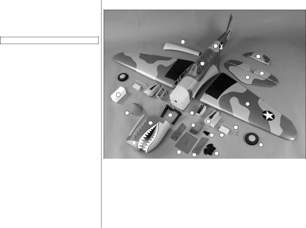
KIT CONTENTS
20
5
|
|
|
|
|
4 |
|
|
6 |
|
|
|
|
|
|
|
|
3 |
|
|
|
|
|
2 |
16 |
|
|
|
|
|
|
|
|
|
|
1 |
19 |
17 |
11 |
|
|
|
|
|
|
|
|
|
|
18 |
21 |
10 |
|
|
|
|
|
|
||
|
|
|
|
8 |
|
|
|
|
|
|
|
|
|
|
12 |
9 |
|
|
|
|
|
|
7 |
|
15 |
14 |
|
13 |
|
|
|
|
|
||
|
|
|
|
|
|
|
|
|
|
|
|
|
|
|
|
|
|
1. |
L/R Wing Panels w/ Ailerons & Flaps |
|
12. |
Headrest |
|
2. |
Horizontal Stabilizer |
|
|
13. |
Instrument Panel |
3. |
L/R Elevator Halves |
|
|
14. |
L/R Cockpit Side Panels |
4. |
Rudder |
|
|
15. |
Cockpit Floor |
5. |
Fuselage |
|
|
16. |
Fuel Tank |
6. |
Canopy |
|
|
17. |
Engine Mount |
7. |
Main Wheels |
|
|
18. |
Cowl |
8. |
L/R Fixed Landing Gear |
|
|
19. |
Spinner |
9. |
Fixed Landing Gear Blocks |
|
|
20. |
Belly Pan |
10. |
L/R Retract Covers |
|
|
21. |
Pilot Seat |
11. |
L/R Landing Gear Mounting Boxes |
|
|
|
|
|
|
|
|
|
|
6
PREPARATIONS
1. If you have not done so already, remove the major parts of the kit from the box and inspect for damage. If any parts are damaged or missing, contact Product Support at the address or telephone number listed in the “Kit Inspection” section on page 5.
2. Carefully remove the tape and separate all the control surfaces. Use a covering iron with a covering sock on medium/high heat to tighten the covering if necessary. Apply pressure over sheeted areas to thoroughly bond the covering to the wood.
ASSEMBLE THE WING
HINGE THE AILERONS & FLAPS
You can do the right wing first so your work matches the photos the first time through, or you can work on them together.
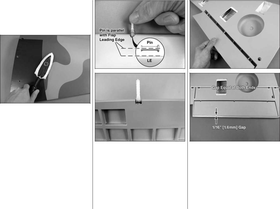
1. Test fi t the included hinge points into the predrilled pockets in the flap. Press the hinge points into the pockets with the pins in the hinge points aligned parallel with the hinge line on the fl ap. Push the hinge points as far deep as they can fi t into the pockets in the fl ap. Work the hinge up and down in the pocket. Be sure that the hinges move freely inside the pocket. If there is any interference, use a hobby knife to slightly enlarge the pocket as necessary.
2. Fit the fl ap to the wing panel by inserting the other ends of the hinge points into the pockets in the wing trailing edge. Position the fl ap so that there is a 1/16" [1.6mm] gap between the fl ap trailing edge and the edge of the recessed area in the wing as shown. Work the fl ap up and down to ensure smooth movement.
7

3. Remove the fl ap from the wing panel and pull the hinge points from the pockets. Coat the center of each hinge point with petroleum jelly or oil. This will prevent epoxy from sticking to the pivoting portion of the hinges.
Before performing steps 4 and 5, have denatured alcohol and some paper towel pieces ready for epoxy cleanup.
4. Mix up a batch of 30-minute epoxy. Use a toothpick or something similar to coat the insides of the hinge point pockets in the fl ap and the wing panel. Wipe away any excess epoxy from around the pockets using a paper towel dampened with alcohol.
5. Coat one end of each hinge point with epoxy. Insert the hinges into the pockets in the fl ap. Use a clean toothpick to scrape out any excess epoxy that may have squeezed out the pocket.
6. Coat the other end of each hinge point with epoxy.Slowly join the fl ap to the wing while wiping away any excess epoxy that squeezes out of the pockets. When the hinge points are all the way inserted into the wing, defl ect the fl ap downward and check the leading
edge for excess epoxy. Position the fl ap in the recess as was done in step #2. When satisfi ed, set the wing aside and allow the epoxy to cure undisturbed.
1" [25mm]

 3/4" [19mm]
Trim the Corners
7. Cut the included 2" x 9" [51mm x 229mm] piece of CA hinge material into 3/4" x 1" [19mm x 25mm] individual hinges. Use a hobby knife or scissors to trim the corners from each hinge to make them easier to insert into the hinge slots.
Drill a 3/32" [2.4mm] hole 1/2" [13mm] deep, in the center of the hinge slot.
Cut the covering away from the slot.
8. Drill a 3/32" [2.4mm] hole 1/2" [13mm] deep in the center of each hinge slot in the wing panel and
8

aileron. Use a sharp hobby knife to carefully cut away the covering just around each hinge slot.
Temporary pin
to keep the hinge
centered.
9. Fit a CA hinge into each hinge slot in the wing panel. If the hinges are diffi cult to install, use a hobby knife to slightly enlarge the slots. Push a pin (T-pins work well for this) through the middle of each hinge to keep them centered.
10. Fit the aileron to the hinges and center it in the opening. Remove the pins from the hinges and position the aileron against the TE of the wing panel. The hinge gap between the aileron and wing should only be wide enough to allow a small line of light through. When satisfi ed, apply 6 drops of thin CA glue to the center of each hinge on both sides. When the CA has dried, gently pull on the aileron to confi rm that it is securely glued in place.
11. Repeat steps 1-10 for the left wing panel.
MOUNT THE SERVOS
Enlarge to 5/64" [2mm]
Cut off unused arms
1. Cut three arms from a four-armed servo arm included with the aileron servo. Enlarge the outer hole of the remaining arm with a 5/64" [2mm] drill bit.
2. Attach a 12" [305mm] servo extension to the aileron servo and secure the connector using tape, heat shrink tubing (not included), or clips specifi cally made for that purpose (Note: If you plan to connect the aileron extensions directly to the receiver without using a Y-harness, you will need servo extensions at least 16" [406mm] in length). Center the servo with your radio system and install the servo arm to the servo perpendicular to the servo case as shown. Be sure to reinstall the servo arm screw into the servo. Install the grommets and eyelets that came packaged with the servo.
3. Center the aileron servo onto the underside of the aileron servo hatch cover. The servo arm should be centered in the opening. Place a 3/4" x 3/4" x 5/16" [19mm x 19mm x 8mm] hardwood servo mounting blocks on each side of the servo against the servo mounting tabs. Use a pencil to mark the positions of the blocks onto the cover.
9

4. Remove the servo from the hatch cover and use epoxy to glue the blocks to the hatch cover.
5. When the epoxy is fully cured, position the servo against the underside of the aileron servo hatch cover between the mounting blocks. Place a piece of paper folded several times between the servo and the hatch cover to space the servo away from the hatch cover. Drill 1/16" [1.6mm] holes through the mounting tabs on the servo case into the blocks. Thread a servo mounting screw (included with the servo) into each hole and back it out. Remove the piece of paper and apply a drop of thin CA to each hole to harden the wood. When the CA has dried, install the servo onto the hatch cover using the hardware supplied with the servo.
6. Use the strings taped inside the aileron servo hatches to pull the servo leads through the wing ribs.
7. Drill a hole into the wing through each hole in the hatch cover using a 1/16" [1.6mm] drill bit. Thread a #2 x 3/8" [9.5mm] self-tapping screw into each hatch mounting hole and back it out. Apply a drop of thin CA to each hole to harden the wood. Install the aileron hatch cover to the wing as shown using four #2 x 3/8" [9.5mm] self-tapping screws and four #2 fl at washers.
8. Mount the fl ap servo and hatch cover in the same way. If using a Y-harness, the fl ap servo requires a 6" [152mm] servo extension. If you plan to connect the fl ap servo directly to the receiver, install a 12" [305mm] extension.
10
 Loading...