


™
IN
MADE
USA
WARRANTY.....Top Flite Models guarantees this kit to be free of defects in both material and workmanship at the date of purchase. This warranty does not cover any component parts damaged by use or modification. In no case shall Top Flite’s liability exceed the original cost of the purchased kit. Further, Top Flite reserves the right to change or modify this warranty without notice.
In that Top Flite has no control over the final assembly or material used for final assembly, no liability shall be assumed nor accepted for any damage resulting from the use by the user of the final user-assembled product. By the act of using the user-assembled product, the user accepts all resulting liability.
If the buyer is not prepared to accept the liability associated with the use of this product, the buyer is advised to immediately return this kit in new and unused condition to the place of purchase.
Top Flite Models
P.O. Box 788
Urbana, Il 61803
Technical Assistance - Call (217) 398-8970
www.top-flite.com
READ THROUGH THIS INSTRUCTION BOOK FIRST. IT CONTAINS IMPORTANT INSTRUCTIONS AND WARNINGS CONCERNING THE ASSEMBLY AND USE OF THIS MODEL.
Entire Contents © Copyright 2002 |
CRS6P03 V3.1 |

............................................Introduction |
3 |
|
|
|
|
|
|
|
................Wing Structure Completion |
14 |
|
|
|
|
|
|
|
.................................Cockpit Finishing |
|
38 |
|||||||||||||||||||||||||||||||||||||||||||||||||||||||||||||||||||||||||||||||||||||||||||||||||||||||||||||||||||||||||||||||||||||||||||||
Precautions ............................................ |
3 |
|
|
|
|
|
|
|
Wing Sheeting...................................... |
15 |
|
|
|
|
|
|
|
Retracts Notes ..................................... |
|
39 |
|||||||||||||||||||||||||||||||||||||||||||||||||||||||||||||||||||||||||||||||||||||||||||||||||||||||||||||||||||||||||||||||||||||||||||||
Die-Cut Patterns ............................... |
4-5 |
|
|
|
|
|
|
|
Fuselage Top........................................ |
19 |
|
|
|
|
|
|
|
Cooling Notes ...................................... |
|
40 |
|||||||||||||||||||||||||||||||||||||||||||||||||||||||||||||||||||||||||||||||||||||||||||||||||||||||||||||||||||||||||||||||||||||||||||||
|
|
|
|
|
|
|
|
|
|
|
|
|
|
|
|
|
|
|
|
|
|
|
|
|
|
|
|
|
|
|
|
|
|
|
|
|
|
|
|
|
|
|
|
|
|
Fuselage Bottom ................................. |
22 |
|
|
|
|
|
|
|
Control Surface Throws ...................... |
|
40 |
||||||||||||||||||||||||||||||||||||||||||||||||||||||||||||||||||||||||||||||||||||||||||||||||||||||||
Decisions You Must Make Early in the |
|
|
|
Wing Mounting..................................... |
26 |
|
|
|
|
|
|
|
Install Receiver, Switch & Battery |
......40 |
|||||||||||||||||||||||||||||||||||||||||||||||||||||||||||||||||||||||||||||||||||||||||||||||||||||||||||||||||||||||||||||||||||||||||||||||||||
Building Process ................................... |
6 |
|
|
|
|
|
|
|
Stab & Fin Mounting............................ |
27 |
|
|
|
|
|
|
|
Balance Your Model............................. |
|
40 |
|||||||||||||||||||||||||||||||||||||||||||||||||||||||||||||||||||||||||||||||||||||||||||||||||||||||||||||||||||||||||||||||||||||||||||||
Engine & Mount Selection .................... |
6 |
|
|
|
|
|
|
|
Firewall & Engine Installation............. |
30 |
|
|
|
|
|
|
|
Final Hookups and Checks................. |
|
41 |
|||||||||||||||||||||||||||||||||||||||||||||||||||||||||||||||||||||||||||||||||||||||||||||||||||||||||||||||||||||||||||||||||||||||||||||
Full Cockpit (optional) ........................... |
6 |
|
|
|
|
|
|
|
Flaps ..................................................... |
31 |
|
|
|
|
|
|
|
Preflight ................................................ |
|
41 |
|||||||||||||||||||||||||||||||||||||||||||||||||||||||||||||||||||||||||||||||||||||||||||||||||||||||||||||||||||||||||||||||||||||||||||||
Flaps..................................................... |
6 |
|
|
|
|
|
|
|
|
|
|
Tips for Robart Hinge Points............... |
33 |
|
|
|
|
|
|
|
|
|
|
Charge the Batteries........................... |
|
41 |
|||||||||||||||||||||||||||||||||||||||||||||||||||||||||||||||||||||||||||||||||||||||||||||||||||||||||||||||||||||||||||||||||||||||
Retracts ............................................... |
6 |
|
|
|
|
|
|
|
Wing Tips ............................................. |
34 |
|
|
|
|
|
|
|
|
|
|
Find a Safe Place to Fly...................... |
|
41 |
||||||||||||||||||||||||||||||||||||||||||||||||||||||||||||||||||||||||||||||||||||||||||||||||||||||||||||||||||||||||||||||||||||||||||
|
|
|
|
|
|
|
|
|
|
|
|
|
|
|
|
|
|
|
|
|
|
|
|
|
|
|
|
|
|
|
|
|
|
|
|
|
|
|
|
|
|
|
|
|
|
Ailerons ................................................ |
34 |
|
|
|
|
|
|
|
|
|
|
Ground Check the Model.................... |
|
41 |
|||||||||||||||||||||||||||||||||||||||||||||||||||||||||||||||||||||||||||||||||||||||||||||||||||||
Common Abbreviations ........................ |
6 |
|
|
|
|
|
|
|
Finishing............................................... |
35 |
|
|
|
|
|
|
|
|
|
|
Range Check Your Radio ................... |
|
41 |
||||||||||||||||||||||||||||||||||||||||||||||||||||||||||||||||||||||||||||||||||||||||||||||||||||||||||||||||||||||||||||||||||||||||||
Types of Wood ....................................... |
6 |
|
|
|
|
|
|
|
|
|
|
Cowl Finishing .................................... |
35 |
|
|
|
|
|
|
|
|
|
|
Engine Safety Precautions ................. |
|
41 |
|||||||||||||||||||||||||||||||||||||||||||||||||||||||||||||||||||||||||||||||||||||||||||||||||||||||||||||||||||||||||||||||||||||||
Supplies & Tools Needed...................... |
6 |
|
|
|
|
|
|
|
|
|
|
Final Sanding ..................................... |
35 |
|
|
|
|
|
|
|
|
|
|
|
|
|
|
|
|
|
|
|
|
|
|
|
|
|
|
|
|
|
|
|
|
|
|
|
|
|
|
|
|
|
|
|
|
|
|
|
|||||||||||||||||||||||||||||||||||||||||||||||||||||||||||||||||||||||||||||||||||||||||||||||||||||
Other Items Required ............................ |
7 |
|
|
|
|
|
|
|
|
|
|
Fuelproofing........................................ |
35 |
|
|
|
|
|
|
|
AMA Safety code ................................. |
|
42 |
||||||||||||||||||||||||||||||||||||||||||||||||||||||||||||||||||||||||||||||||||||||||||||||||||||||||||||||||||||||||||||||||||||||||||
Get Ready to Build................................. |
7 |
|
|
|
|
|
|
|
|
|
|
|
|
|
|
|
|
|
|
|
|
|
|
|
|
|
|
|
|
|
|
|
|
|
|
|
|
|
|
|
|
|
|
|
|
|
|
|
|
|
|
|
|
|
|
|
|
|
|
|
|
|
|
|
|
|
|
|
|
|
|
|
|
|
|
|
|
|
|
|
|
|
|
|
|
|
|
|
|
|
|
|
|
|
|
|
|
|
|
|
|
|
|
|
|
|
|
|
|
|
|
|
|
|
|
|
|
|
|
|
|
|
|
|
|||||||||||||||||||||||||||||||||||||
Build the Stab ........................................ |
7 |
|
|
|
|
|
|
|
Balance the Airplane Laterally ........... |
36 |
|
|
|
|
|
|
|
Flying .................................................... |
|
42 |
|||||||||||||||||||||||||||||||||||||||||||||||||||||||||||||||||||||||||||||||||||||||||||||||||||||||||||||||||||||||||||||||||||||||||||||
Build the Fin .......................................... |
8 |
|
|
|
|
|
|
|
Covering ............................................... |
36 |
|
|
|
|
|
|
|
|
|
|
Takeoff ................................................ |
|
42 |
||||||||||||||||||||||||||||||||||||||||||||||||||||||||||||||||||||||||||||||||||||||||||||||||||||||||||||||||||||||||||||||||||||||||||
Build the Elevators ................................ |
8 |
|
|
|
|
|
|
|
|
|
|
Recommended Covering Sequence... |
36 |
|
|
|
|
|
|
|
|
|
|
Flight................................................... |
|
43 |
|||||||||||||||||||||||||||||||||||||||||||||||||||||||||||||||||||||||||||||||||||||||||||||||||||||||||||||||||||||||||||||||||||||||
Build the Rudder.................................... |
9 |
|
|
|
|
|
|
|
|
|
|
|
|
|
|
|
|
|
|
|
|
|
|
|
|
|
|
|
|
|
|
|
|
|
|
|
|
|
|
|
|
|
|
|
|
|
|
|
|
|
|
|
|
|
|
|
|
|
|
|
|
|
|
|
|
|
|
|
|
|
|
|
|
|
|
|
|
|
|
|
|
|
|
|
|
|
|
Landing............................................... |
|
43 |
|||||||||||||||||||||||||||||||||||||||||||||||||||||||||||||||||||||||
Build the Wing ..................................... |
10 |
|
|
|
|
|
|
|
Apply the Decals & Trim...................... |
36 |
|
|
|
|
|
|
|
|
|
|
Flap Operation.................................... |
|
43 |
||||||||||||||||||||||||||||||||||||||||||||||||||||||||||||||||||||||||||||||||||||||||||||||||||||||||||||||||||||||||||||||||||||||||||
Tip Panels............................................. |
12 |
|
|
|
|
|
|
|
Hinging ................................................. |
37 |
|
|
|
|
|
|
|
Three-view drawing .............. |
Back cover |
||||||||||||||||||||||||||||||||||||||||||||||||||||||||||||||||||||||||||||||||||||||||||||||||||||||||||||||||||||||||||||||||||||||||||||||
Wing Joining ........................................ |
13 |
|
|
|
|
|
|
|
Final Control Hardware Hookups....... |
38 |
|
|
|
|
|
|
|
|
|
|
|
|
|
|
|
|
|
|
|
|
|
|
|
|
|
|
|
|
|
|
|
|
|
|
|
|
|
|
|
|
|
|
|
|
|
|
|
||||||||||||||||||||||||||||||||||||||||||||||||||||||||||||||||||||||||||||||||||||||||||||||||||||||||
|
|
|
|
|
|
|
|
|
|
|
|
|
|
|
|
|
|
|
|
|
|
|
|
|
|
|
|
|
|
|
|
|
|
|
|
|
|
|
|
|
|
|
|
|
|
|
|
|
|
|
|
|
|
|
|
|
|
|
|
|
|
|
|
|
|
|
|
|
|
|
|
|
|
|
|
|
|
|
|
|
|
|
|
|
|
|
|
|
|
|
|
|
|
|
|
|
|
|
|
|
|
|
|
|
|
|
|
|
|
|
|
|
|
|
|
|
|
|
|
|
|
|
|
|
|
|
|
|
|
|
|
|
|
|
|
|
|
|
|
|
|
|
|
|
|
|
|
|
|
|
|
|
|
|
|
|
|
|
|
|
|
|
|
|
|
|
|
|
|
|
|
|
|
|
|
|
|
|
|
|
|
|
|
|
|
|
|
|
|
|
|
|
|
|
|
|
|
|
|
|
|
|
|
|
|
|
|
|
|
|
|
|
|
|
|
|
|
|
|
|
|
|
|
|
|
|
|
|
|
|
|
|
|
|
|
|
|
|
|
|
|
|
|
|
|
|
|
|
|
|
|
|
|
|
|
|
|
|
|
|
|
|
|
|
|
|
|
|
|
|
|
|
|
|
|
|
|
|
|
|
|
|
|
|
|
|
|
|
|
|
|
|
|
|
|
|
|
|
|
|
|
|
|
|
|
|
|
|
|
|
|
|
|
|
|
|
|
|
|
|
|
|
|
|
|
|
|
|
|
|
|
|
|
|
|
|
|
|
|
|
|
|
|
|
|
|
|
|
|
|
|
|
|
|
|
|
|
|
|
|
|
|
|
|
|
|
|
|
|
|
|
|
|
|
|
|
|
|
|
|
|
|
|
|
|
|
|
|
|
|
|
|
|
|
|
|
|
|
|
|
|
|
|
|
|
|
|
|
|
|
|
|
|
|
|
|
|
|
|
|
|
|
|
|
|
|
|
|
|
|
|
|
|
|
|
|
|
|
|
|
|
|
|
|
|
|
|
|
|
|
|
|
|
|
|
|
|
|
|
|
|
|
|
|
|
|
|
|
|
|
|
|
|
|
|
|
|
|
|
|
|
|
|
|
|
|
|
|
|
|
|
|
|
|
|
|
|
|
|
|
|
|
|
|
|
|
|
|
|
|
|
|
|
|
|
|
|
|
|
|
|
|
|
|
|
|
|
|
|
|
|
|
|
|
|
|
|
|
|
|
|
|
|
|
|
|
|
|
|
|
|
|
|
|
|
|
|
|
|
|
|
|
|
|
|
|
|
|
|
|
|
|
|
|
|
|
|
|
|
|
|
|
|
|
|
|
|
|
|
|
|
|
|
|
|
|
|
|
|
|
|
|
|
|
|
|
|
|
|
|
|
|
|
|
|
|
|
|
|
|
|
|
|
|
|
|
|
|
|
|
|
|
|
|
|
|
|
|
|
|
|
|
|
|
|
|
|
|
|
|
|
|
|
|
|
|
|
|
|
|
|
|
|
|
|
|
|
|
|
|
|
|
|
|
|
|
|
|
|
|
|
|
|
|
|
|
|
|
|
|
|
|
|
|
|
|
|
|
|
|
|
|
|
|
|
|
|
|
|
|
|
|
|
|
|
|
|
|
|
|
|
|
|
|
|
|
|
|
|
|
|
|
|
|
|
|
|
|
|
|
|
|
|
|
|
|
|
|
|
|
|
|
|
|
|
|
|
|
|
|
|
|
|
|
|
|
|
|
|
|
|
|
|
|
|
|
|
|
|
|
|
|
|
|
|
|
|
|
|
|
|
|
|
|
|
|
|
|
|
|
|
|
|
|
|
|
|
|
|
|
|
|
|
|
|
|
|
|
|
|
|
|
|
|
|
|
|
|
|
|
|
|
|
|
|
|
|
|
|
|
|
|
|
|
|
|
|
|
|
|
|
|
|
|
|
|
|
|
|
|
|
|
|
|
|
|
|
|
|
|
|
|
|
|
|
|
|
|
|
|
|
|
|
|
|
|
|
|
|
|
|
|
|
|
|
|
|
|
|
|
|
|
|
|
|
|
|
|
|
|
|
|
|
|
|
|
|
|
|
|
|
|
|
|
|
|
|
|
|
|
|
|
|
|
|
|
|
|
|
|
|
|
|
|
|
|
|
|
|
|
|
|
|
|
|
|
|
|
|
|
|
|
|
|
|
|
|
|
|
|
|
|
|
|
|
|
|
|
|
|
|
|
|
|
|
|
|
|
|
|
|
|
|
|
|
|
|
|
|
|
|
|
|
|
|
|
|
|
|
|
|
|
|
|
|
|
|
|
|
|
|
|
|
|
|
|
|
|
|
|
|
|
|
|
|
|
|
|
|
|
|
|
|
|
|
|
|
|
|
|
|
|
|
|
|
|
|
|
|
|
|
|
|
|
|
|
|
|
|
|
|
|
|
|
|
|
|
|
|
|
|
|
|
|
|
|
|
|
|
|
|
|
|
|
|
|
|
|
|
|
|
|
|
|
|
|
|
|
|
|
|
|
|
|
|
|
|
|
|
|
|
|
|
|
|
|
|
|
|
|
|
|
|
|
|
|
|
|
|
|
|
|
|
|
|
|
|
|
|
|
|
|
|
|
|
|
|
|
|
|
|
|
|
|
|
|
|
|
|
|
|
|
|
|
|
|
|
|
|
|
|
|
|
|
|
|
|
|
|
|
|
|
|
|
|
|
|
|
|
|
|
|
|
|
|
|
|
|
|
|
|
|
|
|
|
|
|
|
|
|
|
|
|
|
|
|
|
|
|
|
|
|
|
|
|
|
|
|
|
|
|
|
|
|
|
|
|
|
|
|
|
|
|
|
|
|
|
|
|
|
|
|
|
|
|
|
|
|
|
|
|
|
|
|
|
|
|
|
|
|
|
|
|
|
|
|
|
|
|
|
|
|
|
|
|
|
|
|
|
|
|
|
|
|
|
|
|
|
|
|
|
|
|
|
|
|
|
|
|
|
|
|
|
|
|
|
|
|
|
|
|
|
|
|
|
|
|
|
|
|
|
|
|
|
|
|
|
|
|
|
|
|
|
|
|
|
|
|
|
|
|
|
|
|
|
|
|
|
|
|
|
|
|
|
|
|
|
|
|
|
|
|
|
|
|
|
|
|
|
|
|
|
|
|
|
|
|
|
|
|
|
|
|
|
|
|
|
|
|
|
|
|
|
|
|
|
|
|
|
|
|
|
|
|
|
|
|
|
|
|
|
|
|
|
|
|
|
|
|
|
|
|
|
|
|
|
|
|
|
|
|
|
|
|
|
|
|
|
|
|
|
|
|
|
|
|
|
|
|
|
|
|
|
|
|
|
|
|
|
|
|
|
|
|
|
|
|
|
|
|
|
|
|
|
|
|
|
|
|
|
|
|
|
|
|
|
|
|
|
|
|
|
|
|
|
|
|
|
|
|
|
|
|
|
|
|
|
|
|
|
|
|
|
|
|
|
|
|
|
|
|
|
|
|
|
|
|
|
|
|
|
|
|
|
|
|
|
|
|
|
|
|
|
|
|
|
|
|
|
|
|
|
|
|
|
|
|
|
|
|
|
|
|
|
|
|
|
|
|
|
|
|
|
|
|
|
|
|
|
|
|
|
|
|
|
|
|
|
|
|
|
|
|
|
|
|
|
|
|
|
|
|
|
|
|
|
|
|
|
|
|
|
|
|
|
|
|
|
|
|
|
|
|
|
|
|
|
|
|
|
|
|
|
|
|
|
|
|
|
|
|
|
|
|
|
|
|
|
|
|
|
|
|
|
|
|
|
|
|
|
|
|
|
|
|
|
|
|
|
|
|
|
|
|
|
|
|
|
|
|
|
|
|
|
|
|
|
|
|
|
|
|
|
|
|
|
|
|
|
|
|
|
|
|
|
|
|
|
|
|
|
|
|
|
|
|
|
|
|
|
|
|
|
|
|
|
|
|
|
|
|
|
|
|
|
|
|
|
|
|
|
|
|
|
|
|
|
|
|
|
|
|
|
|
|
|
|
|
|
|
|
|
|
|
|
|
|
|
|
|
|
|
|
|
|
|
|
|
|
|
|
|
|
|
|
|
|
|
|
|
|
|
|
|
|
|
|
|
|
|
|
|
|
|
|
|
|
|
|
|
|
|
|
|
|
|
|
|
|
|
|
|
|
|
|
|
|
|
|
|
|
|
|
|
|
|
|
|
|
|
|
|
|
|
|
|
|
|
|
|
|
|
|
|
|
|
|
|
|
|
|
|
|
|
|
|
|
|
|
|
|
|
|
|
|
|
|
|
|
|
|
|
|
|
|
|
|
|
|
|
|
|
|
|
|
|
|
|
|
|
|
|
|
|
|
|
|
|
|
|
|
|
|
|
|
|
|
|
|
|
|
|
|
|
|
|
|
|
|
|
|
|
|
|
|
|
|
|
|
|
|
|
|
|
|
|
|
|
|
|
|
|
|
|
|
|
|
|
|
|
|
|
|
|
|
|
|
|
|
|
|
|
|
|
|
|
|
|
|
|
|
|
|
|
|
|
|
|
|
|
|
|
|
|
|
|
|
|
|
|
|
|
|
|
|
|
|
|
|
|
|
|
|
|
|
|
|
|
|
|
|
|
|
|
|
|
|
|
|
|
|
|
|
|
|
|
|
|
|
|
|
|
|
|
|
|
|
|
|
|
|
|
|
|
|
|
|
|
|
|
|
|
|
|
|
|
|
|
|
|
|
|
|
|
|
|
|
|
|
|
|
|
|
|
|
|
|
|
|
|
|
|
|
|
|
|
|
|
|
|
|
|
|
|
|
|
|
|
|
|
|
|
|
|
|
|
|
|
|
|
|
|
|
|
|
|
|
|
|
|
|
|
|
|
|
|
|
|
|
|
|
|
|
|
|
|
|
|
|
|
|
|
|
|
|
|
|
|
|
|
|
|
|
|
|
|
|
|
|
|
|
|
|
|
|
|
|
|
|
|
|
|
|
|
|
|
|
|
|
|
|
|
|
|
|
|
|
|
|
|
|
|
|
|
|
|
|
|
|
|
|
|
|
|
|
|
|
|
|
|
|
|
|
|
|
|
|
|
|
|
|
|
|
|
|
|
|
|
|
|
|
|
|
|
|
|
|
|
|
|
|
|
|
|
|
|
|
|
|
|
|
|
|
|
|
|
|
|
|
|
|
|
|
|
|
|
|
|
|
|
|
|
|
|
|
|
|
|
|
|
|
|
|
|
|
|
|
|
|
|
|
|
|
|
|
|
|
|
|
|
|
|
|
|
|
|
|
|
|
|
|
|
|
|
|
|
|
|
|
|
|
|
|
|
|
|
|
|
|
|
|
|
|
|
|
|
|
|
|
|
|
|
|
|
|
|
|
|
|
|
|
|
|
|
|
|
|
|
|
|
|
|
|
|
|
|
|
|
|
|
|
|
|
|
|
|
|
|
|
|
|
|
|
|
|
|
|
|
|
|
|
|
|
|
|
|
|
|
|
2

PROTECT YOUR MODEL, YOURSELF & OTHERS – FOLLOW THIS IMPORTANT SAFETY PRECAUTION
Your Top Flite F4U Corsair is not a toy, but rather a sophisticated, working model that functions very much like an actual airplane.
Because of its performance, the Corsair, if not assembled and operated correctly, could possibly cause injury to yourself or spectators and damage property.
To make your R/C modeling experience totally enjoyable, we recommend that you get experienced, knowledgeable help with assembly and during your first flights. You’ll learn faster and avoid risking your model before you’re truly ready to solo. Your local hobby shop has information about flying clubs in your area whose membership includes qualified instructors.
You can also contact the national Academy of Model Aeronautics (AMA), which has more than 2,500 chartered clubs across the country. Through any one of them, instructor training programs and insured newcomer training are available.
Contact the AMA at the address or toll-free phone number below:
Academy of Model Aeronautics
5151 East Memorial Drive
Muncie, IN 47302-9252
Telephone: (800) 435-9262
Fax: (317) 741-0057
INTRODUCTION
Thank you for purchasing the Top Flite GOLD EDITION Corsair.
The Top Flite F4U Corsair is a sport scale model of the Chance Vought F4U Corsair. This kit may be built as a sport model for sport flying or detailed out for sport scale competition. Either way, the model possesses a very good scale outline.
The decals in the kit (and shown on the box cover) duplicate a Korean war vintage F4U-4 Corsair which lends itself well to a MonoKote® covering. Most other types of the Corsair line, such as the F4U-1A, may be built from this kit with minor modifications.
Several color photo sets and 3-view drawings suitable for sport scale documentation are available from:
Scale Model Research
3114 Yukon Ave.
Costa Mesa, CA 92626
(714) 979-8058
The Top Flite Corsair is designed to fly as good as it looks. The outer wing panels have jig tabs that automatically build in approx. 1-1/4 degrees of washout to prevent tip stalling. The computerdesigned, interlocking structure allows you to build a straight and true model that will fly great.
This model aircraft is not for beginners. The Top Flite Corsair has excellent flight characteristics and is very maneuverable, but it is quite fast and does not have the required stability and self recovery characteristics of a good R/C trainer. A pilot should be confident flying a sport aircraft with ailerons before attempting to fly the Corsair.
Please inspect all parts carefully before starting to build! If any parts are missing, broken or defective, or if you have any questions about building or flying this model, please call us at (217) 398-8970 and we'll be glad to help. If you are calling for replacement parts, please look up the part numbers and the kit identification number (stamped on the end of the carton) and have them ready when calling.
PRECAUTIONS
1.You must build the plane according to the plan and instructions. Do not alter or modify the model, as doing so may result in an unsafe or unflyable model. In a few cases the plan and instructions may differ slightly from the photos. In those instances you should assume the plan and written instructions are correct.
2.You must take time to build straight, true and strong.
3.You must use a proper R/C radio that is in first class condition, the correct sized engine and correct components (fuel tank, wheels, etc.) throughout your building process.
4.You must properly install all R/C and other components so that the model operates properly on the ground and in the air.
5.You must test the operation of the model before the first and each successive flight to insure that all equipment is operating, and you must make certain that the model has remained structurally sound. Be sure to check external nylon clevises often. Replace any that show signs of wear.
6.You must fly the model only with the competent help of a well experienced R/C pilot if you are not already an experienced R/C pilot at this time.
Remember: Take your time and follow directions to end up with a well-built model that is straight and true.
NOTE: We, as the kit manufacturer, can provide you with a top quality kit and great instructions, but ultimately the quality and flyability of your finished model depends on how you build it; therefore, we cannot in any way guarantee the performance of your completed model, and no representations are expressed or implied as to the performance or safety of your completed model.
3

DIE-CUT PARTS |
4 |

DIE-CUT PARTS |
5 |

DECISIONS YOU MUST MAKE
EARLY IN THE
BUILDING SEQUENCE
ENGINE AND MOUNT SELECTION
The recommended engine size range is as follows:
.60 to .90 cu. in. 2-stroke
.90 to 1.20 cu. in. 4-stroke
NOTE: The smaller engines in the range provide more than enough power to fly the Corsair well. Do not hesitate to use them.
The instructions show an OS® .61 2-stroke engine side mounted at a 45 degree inverted position. It also shows a Top Flite internal muffler (TOPQ7915). This power package works very well. Most .61 2-stroke engines will fit in the supplied EM60120 engine mount.
The instructions also show the installation of an OS 1.20 4-stroke engine. Even though it is shown mounted inverted, it could also be mounted upright or on its side; the decision is yours. Flexible exhaust systems are available for most 4-stroke engines and there is more than enough room inside the Corsair’s cowl to route the exhaust out the bottom. You would also have to change the cowl mounting. The engine is shown on the plans mounted to a JT-122 SV isolation mount which may no longer be available. The supplied EM60120 mount will fit the O.S. 1.20.
FULL COCKPIT (Optional)
You must decide before you build the fuselage if you will be adding the optional full cockpit kit (TOPQ8404) to your Corsair. If you are undecided, you should build it as though you are going to install it. That way you can add it at a later time should you want to.
FLAPS
You must decide early in the building process if you are going to use operating wing flaps. These are not required but do add to the Corsair's appearance and flyability. The flaps as described in this manual work very well, giving super stable slow flight with virtually no trim changes. Obviously there is some extra work and craftsmanship required to fit operating flaps to the model. If you use operating flaps, you will need to have (2) standard servos and small Robart hinge points (ROBQ2508) available during construction.
RETRACTS
You will need to decide early whether you intend to use retractable landing gear in your Corsair. Robart 100 degree rotating retracts (ROBQ1815) were used in the prototypes and the rib spacing and mounts in the kit are designed to accept them. Century Jet Models 90 degree rotating retracts (CJMQ3055) will also work as well. Other retracts have not been tested.
COMMON ABBREVIATIONS USED IN |
|
|
TYPES OF WOOD |
||||
|
|||||||
|
THIS BOOK AND ON THE PLANS: |
|
|
|
|||
Deg. = Degrees |
Ply |
= |
Plywood |
|
|
|
|
Elev = Elevator |
Rt |
= |
Right |
|
|
|
|
Fuse = Fuselage |
Stab = |
Stabilizer |
|
|
|
||
LE |
= Leading Edge |
TE |
= |
Trailing Edge |
|
|
|
|
(front) |
|
|
(rear) |
|
|
|
LG |
= Landing Gear |
" |
= |
Inches |
|
|
|
|
|||||||
Lt |
= Left |
Tri |
= |
Triangle |
|
|
|
|
|
|
|
|
|
|
|
6
OTHER ITEMS REQUIRED |
|
Plastic Pilot: Williams Bros. Standard, 2" Scale |
|
||
|
|
|
Four-Channel Radio with 4 servos (additional |
|
#17600 (WBRQ1050) |
|
Main Gear Retracts (optional)...Robart #615 |
|
channels and servos required if retracts and/or |
|
|
flaps are used). |
|
(ROBQ1815) Century Jet 33325 - complete |
Top Flite Power Point® Propellers (see engine |
|
kit (CJMQ3055) |
instructions for recommended sizes) |
|
Air Control Kit (optional retracts)...Robart |
Prop Safety Nut (Great Planes has sizes and |
|
#188VRX (ROBQ2307) (Not required with CJ |
styles that work nicely) |
|
33325) |
12 oz Fuel Tank (DUBQ0212) |
|
Oleo Robo Struts (optional)...Robart #650 |
5/32" Wheel Collars - 4 (GPMQ4306) |
|
(ROBQ1700) (Not required with CJ 33325) |
3/32" Wheel Collars - 2 (GPMQ4302) |
|
Hinge Points (optional flaps)...Robart #308 |
Top Flite MonoKote Covering Material (Insignia |
|
(ROBQ2508) |
Blue and Yellow) |
|
3-1/4" Main Wheels...Robart #134 (ROBQ1534) |
Fuelproof Paint* for Cowl, Canopy and Oil |
|
1-1/4 Tail Wheel (GPMQ4242) |
Coolers (Top Flite LustreKote™ recommended) |
|
.60 to .80 2-stroke, .90 to 1.20 4-stroke |
Latex Foam Rubber Padding, 1/4" thick |
|
|
(HCAQ1000) |
|
NOTE: Top Flite “LustreKote Paint” matches |
Silicone Fuel Tubing (GPMQ4131) |
|
MonoKote covering and is available in aerosol cans. |
|
|
|
Sanders are made from lightweight extruded aluminum and can be found at most hobby shops. They are available in three sizes – 5-1/2" (GPMR6169) – 11" (GPMR6170) for most general purpose sanding and 22" (GPMR6172) for long surfaces such as wing leading edges. We recommend using the 2" wide self-adhesive sandpaper sold in 12' rolls by Great Planes. Standard sandpaper can be attached by gluing it to the sander with brush-on rubber cement. Apply the rubber cement to both the bottom of the sander and the back of the sandpaper. When both surfaces are dry to the touch, press the sandpaper firmly onto the sander. Spray adhesive can be used for this purpose but it’s much harder to remove the sandpaper when you need to replace it. Use a knife blade for cutting sandpaper, not your good scissors!
GET READY TO BUILD
1. Unroll the plan sheets. Reroll the plan sheets inside out to make them lie flat.
2. Remove all parts from the box. As you do, determine the name of each part by comparing it with the plan. Using a felt-tip pen, write the part name or size on each piece to avoid confusion later. Use the die-cut patterns shown on pages 4 and 5 to identify the die-cut parts and mark them before punching out. Save all scraps. If any of the die-cut parts are difficult to punch out, do not force them! Instead, first cut around the parts with a hobby knife. After punching out the die-cut parts, use your bar sander or sanding block to lightly sand the edges to remove any die-cutting irregularities.
3. As you identify and mark the parts, separate them into groups, such as fuse (fuselage), wing, fin and stab (stabilizer), and hardware.
BUILD THE STAB
1. Arrange the stab portion of the plan on a flat building board (you may wish to cut out the stab section). Cover the area over the stab with waxed paper.
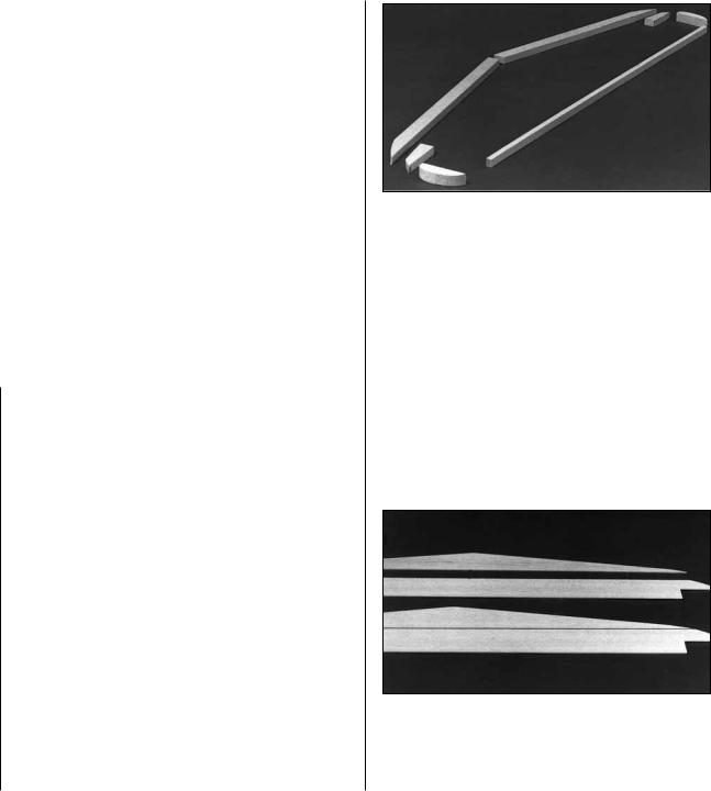
2. Cut the balsa 3/8" x 5/8" x 24" LE stock to fit nicely at the center joint. Save excess material for the fin LE. Trim the tip of the LE to the approximate shape on the plan but leave about 1/16" excess for final shaping later.
3. Cut the balsa 1/4" x 3/8" x 30" TE stock to the correct length. Extra material is kept for the Fin.
4. Cut the two elevator tip blocks from the 1/2" x 1/2" x 4" balsa stick provided. Shape the tips to match the plan shape.
5. Make the stab tips from excess 3/8" x 5/8" LE stock. Set the previously made parts aside for now.
6. Make a top and bottom stab skin by placing the 1/16" die-cut balsa pieces, stab front and stab back, together over waxed paper and glue them together with thin CA. Block sand the skins lightly with 220-grit sandpaper.
7
7. Pin the bottom skin to the stab plan. Draw tick marks for the rib spacing on the skin to match the plan. Glue the LE and TE pieces on top of the bottom skin.
8. Cut the “ribs” from two 3/32" x 3/8" x 24" balsa sticks. Align them with the “tick” marks and glue in place. Do not overlook the two angled pieces in the center over the fuse stab base.
9. Check the fit of the stab tips. Sand if necessary, then glue them in place.
10. Use a bar sander to flatten the top of the exposed structure. No parts should be left high or low. Check all glue joints and add glue to any that appear weak.
11. Glue on the top stab skin with medium or slow CA. Be sure to apply glue to all ribs as well as the LE and TE.
12. True the stab tips to match the die-cut stab skins.
13. Draw a centerline around the stab to help you maintain symmetry during sanding. Rough shape the LE and the tips to the approximate cross section shown on the plan.
BUILD THE FIN
1. Trim the 3/8" x 5/8" LE and the 1/4" x 3/8" TE to match the plan. Notice that they extend down into the formers.
2. Make a left and a right fin skin by placing the die-cut 1/16" balsa fin front and fin back together over waxed paper and applying thin CA to the joint. Block sand lightly.
3. Pin the right skin to the plan. Glue the LE and TE on top of the skin.
4. Cut to length and glue in the 3/32" x 3/8" “ribs” where indicated on the plan.
5. Block sand the structure until it is flat.
6. Use medium CA to glue the left fin skin to all the ribs, the LE and the TE.
7. Draw a centerline around the fin to assist you in hinging and shaping. Shape the LE of the fin to match the cross section on the plan.
BUILD THE ELEVATORS
1. Place the 3/32" balsa die-cut elevators over the plan. Mark the locations of the “ribs” on both sides of both elevators.
2. From the grooved 1/2" x 1/2" x 30" balsa control surface LE, cut two pieces to the length shown on the plan.
3. Slide the elevators into the slot in the control surface LE’s. Glue with CA.
8
4. Hang the LE’s over the edge of the table and glue the 3/32" x 1/4" “ribs” (made from 3/32" x 1/4" x 30" balsa) to the elevators at the locations marked earlier.
5. Flip the elevators over onto their other side and glue the “ribs” onto the second side.
6. Center the 3/32" die-cut balsa balance tabs on the forward surfaces of the elevator LE’s. Glue them in position as indicated by the plan.
7. Glue the elevator tip blocks (cut earlier) to the end of the elevators.
8. Cut 2" balsa balance tab LE’s from 1/4" x 1/2" stock. Glue them to the front edge of the elevator as shown on the plan.
9. Cut balance tab root cap strips from leftover balsa 3/32" balsa. Glue them to the root end of the balance tabs as shown on the plan. Glue a rib to the balance tab (made from 3/32" x 1/4" x 30" balsa) between the tip and the root cap strip.
10. Make doubler caps for the root end of each elevator from leftover 1/8" balsa. Glue a cap to the root end of each elevator. Make four torque rod doublers (see plan for shape and location) from leftover 3/32" balsa. Glue them to both sides of the elevators in the locations shown on the plan.
11. Sand the tip of each elevator to match the outline on the plan.
12. Use a bar sander to sand the ribs to match the typical cross-section on the plan. Note that there is some outward curvature to provide the scale ribbed appearance.
13. Tape the elevators to the stab for blending and shaping.
14. Remove the elevators and shape the LE to a “V” as shown on the cross-section if you are using the standard hinging technique. (See the Hinging section and the plan sheets for alternatives.)
BUILD THE RUDDER
1. Trim the grooved 1/2" x 1/2" balsa LE (left over from the elevators) to the length shown on the plan. Cut the balance tab LE from the 1/4" x 1/2" stock.
2. Join the 3/32" die-cut balsa rudder pieces, rudder front and rudder back together with CA. Mark the “rib” locations on both sides of the rudder.
3. Glue the rudder sheet into the slot in the rudder LE.
4. Cut “ribs” from the 3/32" x 1/4" x 30" balsa sticks and glue them to both sides of the rudder.
5. Glue the 1/4" x 1/2" balance tab LE to the front edge of the rudder.
Photo for steps 1-6
6. Make doublers from leftover 3/32" sheet to reinforce the area where the torque rod protrudes into the rudder (see plan for location).
7. Shape the rudder to match the photos and the typical cross-section on the plan. Tape the rudder to the fin for shaping.
8. Shape the LE to a “V” as shown on the cross-section if you are using the standard hinging technique.
9

BUILD THE WING
WING CENTER SECTION
NOTE: The center section main spar is made of one die-cut 1/8" plywood piece sandwiched between two die-cut 1/16" birch plywood pieces.
NOTE: The wing root ribs are stamped only with a number (2 is R-2), the wing tip ribs are stamped with T and a number (T 4 is T-4).
1. Lightly sand the surfaces of the three pieces that make up the main spar to make sure they will lie flat together for a good glue joint.
2. Make some short sticks from leftover 1/8" balsa to key the rib slots together and assure proper alignment during gluing. Test fit pieces.
3. Use 30-minute epoxy to glue the spar pieces together. Use weights to hold them flat on the table while the glue cures. Apply thin CA on the edges of the spar, especially to areas that do not appear to be well glued.
4. Clean up the edges of the spar with sandpaper. If you will be installing retracts, you may want to cut any holes required for your retracts in the spar at this time. See the instructions that came with your retracts.
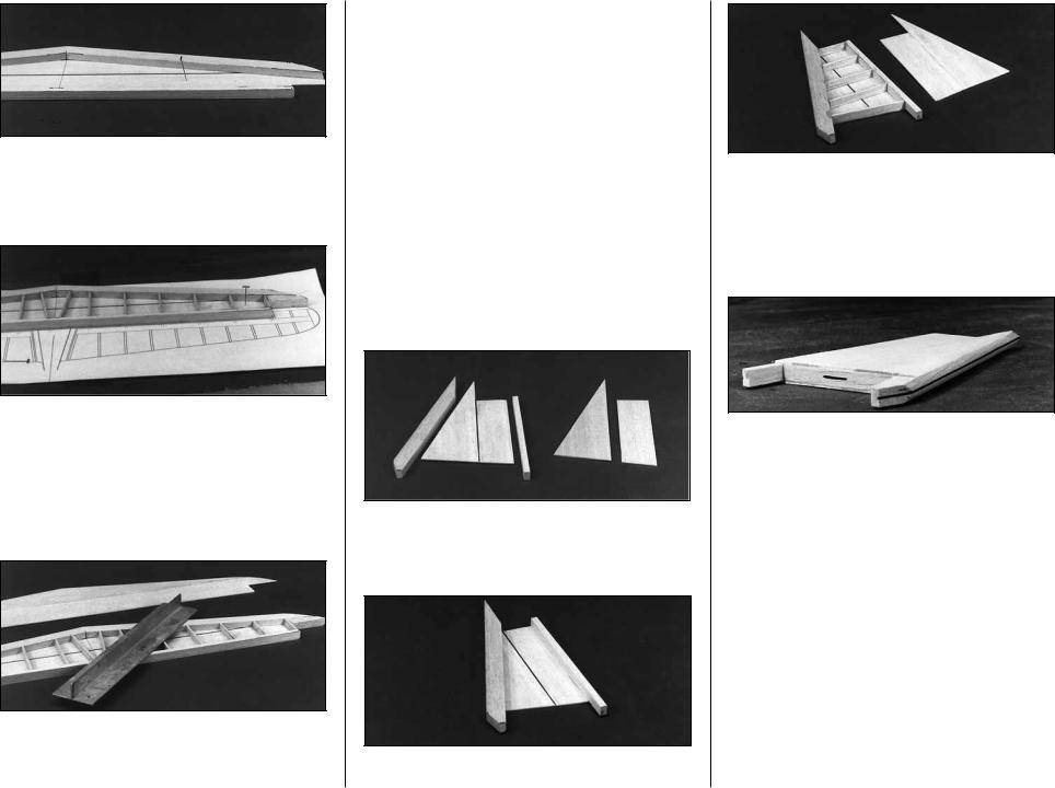
5. Join the die-cut 3/16" balsa aft leading edge pieces at the center over the template provided on the plan. Use the plan to mark the rib locations on the aft LE. Glue the die-cut 3/16" balsa fwd leading edge pieces to the aft leading edge. (Center the fwd leading edge on the aft leading edge as shown on the cross-sectional view.) Refer to the photo - do not put glue where indicated.
6. Join the die-cut 3/16" balsa fwd trailing edge pieces at the center over the template provided on the plan. Use the plan to mark the rib locations on the fwd TE. Glue the die-cut 3/16" balsa aft trailing edge pieces to the fwd trailing edge. (Center the aft trailing edge on the fwd trailing edge as shown on the cross-sectional view.)
7. The hatched area of the forward LE which was not glued may be cut loose with a razor saw and removed after the glue has set on the rest of the part.
8. Drill 3/16" holes through all ribs and doublers that require them for aileron linkage routing. These holes are located by punch marks in the ribs just aft of the spar.
9. Glue the die-cut 1/16" plywood R-2B rib doublers to the die-cut 3/32" balsa R-2 ribs. Glue the plywood R-3B rib doublers to the balsa R-3 ribs. Be sure to make a left and a right of each assembly. Trial fit the R-3 assembly into the spar slot – you may find it necessary to bevel the plywood doubler along the top side a little for a smooth transition.
10. Glue the die-cut 1/8" balsa R-4B sub ribs to the die-cut 1/8" balsa R-4 ribs. Glue the R-5B sub ribs to the R-5 ribs. Be sure to make a left and a right of each assembly.
10
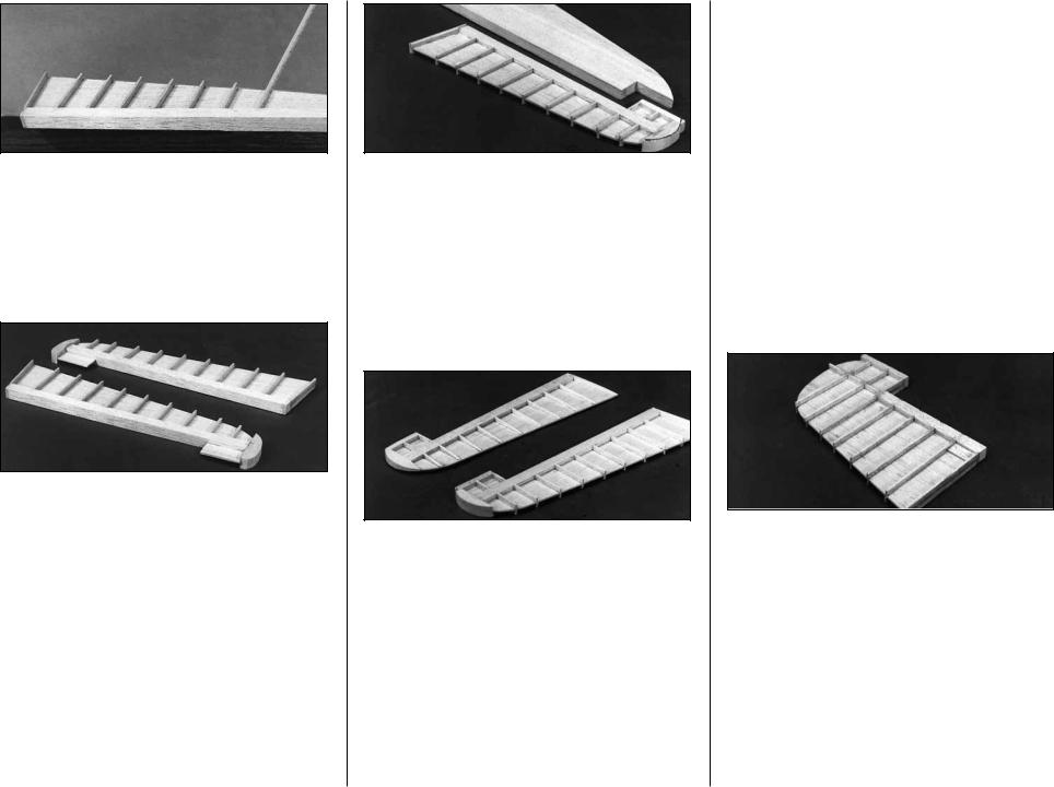
11. Plug the die-cut ribs R-1 to R-6 into the spar. Hold this assembly over the plan to make sure the ribs are perpendicular to the spar and not skewed. When you are satisfied that all ribs are fitting properly, lightly glue them in place with a drop of CA. You will glue all these joints thoroughly after the LE, TE and a few other parts are installed.
12. Make a couple of 1/2" tall balsa blocks to support the ends of the R-1’s and prevent the center section from twisting. Tack glue these to the R-1’s.
13. Slide the die-cut balsa well doublers (WD) into place - do not glue yet.
14. Glue the TE assembly in place. Check the center section on a flat table to be sure it is not twisted. Flex and reglue joints to take out any warps.
15. Align the LE assembly onto the front edge of the wing. Glue only to ribs R-1, R-2 and R-3.
16. Glue the die-cut 3/16" balsa LE triplers in place between R-3 and R-5. Glue ribs R-4 and R-5 to the LE.
17. Glue both 1/8" die-cut plywood dowel plates (DP and ADP) in place as shown on plan. Glue the R-6’s to the LE. Drill a hole through the LE of the wing through the hole in the forward dowel plate (DP). Start with a small drill and gradually increase the size to 5/16".
18. If you are using retracts, glue in the die-cut 1/16" plywood spar doublers (SD) on both sides of the spar using 30-minute epoxy. Cut a notch in
the main spar to match the strut cutout in (SD). The notch will probably need to be deepened slightly during final retract fitting. Keep this cut smoothly radiused to prevent the creation of a weak spot in the wing. A small Dremel® drum sander is helpful here. See Page 42 for details on retract installation.
19. If you are using fixed landing gear, assemble both sets of fixed gear parts with 30-minute epoxy as follows:
A. Drill the holes in the 1/8" x 1-13/16" x 3" 5-ply plates using the pattern on the wing plan.
B. Glue each basswood 7/16" x 5/8" x 7/8" landing gear retainer block to a grooved bass landing gear mount.
C. Refering to the drawing on the wing plan, drill a 5/32" hole where shown into each Grooved LG mount and through each LG retainer block.
D. Slide a 1/8" plywood plate onto each main landing gear wire. Trial fit the LG block assemblies, relieve any parts if necessary to allow the 1/8" plates and the block assemblies to almost come together (a little pressure during final assembly is good).
NOTE: The wire Landing Gear in the kit differs in appearance from the wire LG in the photos.
E. Drill the four 5/64" holes shown in each basswood block assembly for the #4 x 1/2" sheet metal screws, using the 1/8" plate as a pattern.
11

F. Disassemble the parts and enlarge the hole drilled in the previous step in the 1/8" plate to 1/8" for clearance.
G. Reassemble the fixed gear parts.
20. Measure and drill the gear mounting holes in the 1/4" x 5/16" x 3" plywood mounting rails. Mount the fixed gear plates or retracts – test fit between R-2B and R-3B while holding the 1/16" die-cut plywood R-3C gear reinforcement tripler in place (if you are using retracts, make sure the retract will clear the wing skins). Adjust the height of R-3C if necessary. Do this for both wing panels.
21. Glue the R-3C’s in position.
22. Tilt the LG assemblies (fixed or retract) until the struts protrude straight down (the left and right struts should be parallel to each other and perpendicular to the ground). Check the fit of the R-2C’s, adjust their height if necessary, then glue them in place. Glue in the mounting rails.
23. Remove the LG assemblies and apply a small fillet of 30-minute epoxy to all joints involving plywood in the landing gear mounting areas. Apply some epoxy to the dowel plate joints also.
24. Glue all ribs to the spar. Glue both WD’s to ribs R-1, R-2, R-3 and R-4. Reinforce any glue joints that appear weak.
TIP PANELS
NOTE: The tip panels are built “UPSIDE-DOWN” on the plan (the jig tabs are attached to what is, in the end, the TOP surface of the wing.)
1. Place the tip panel plan over a flat building board (you may wish to cut out these sections of the plan sheet). Cover with waxed paper.
2. Cut the top 1/4" x 3/8" x 20" hard balsa spar to length. Pin it in place over the plan.
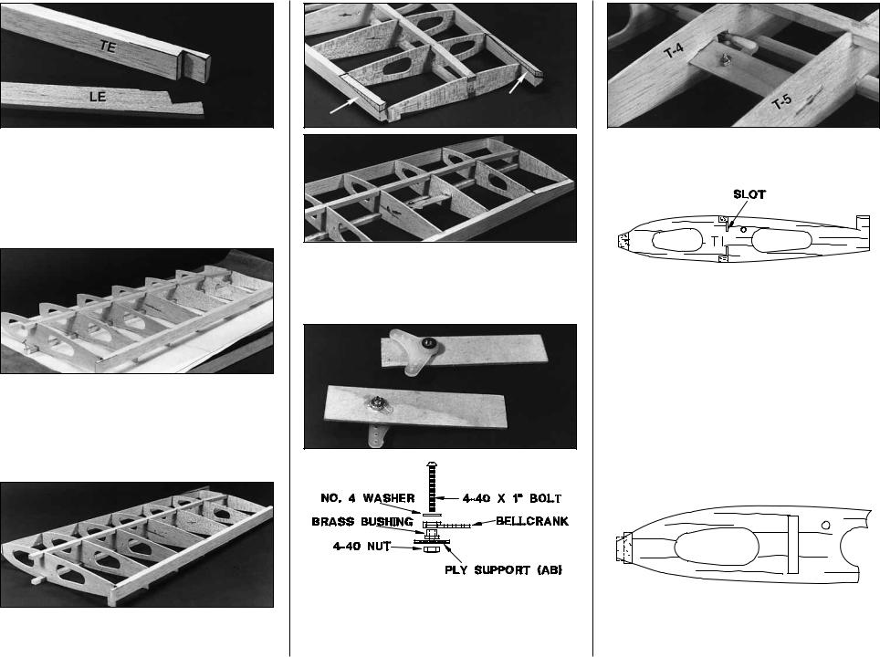
3. Cut a 1/16" slot in the 3/32" balsa die-cut ribs T-4 and T-5 between the punch marks provided to allow the bellcrank platform to slide in place later.
4. Glue die-cut 3/32" balsa ribs T-1 through T-7 to the spar with the jig tabs at the TE flat against the work surface.
5. Cut a V-notch in the bottom 1/4" x 3/8" x 20" balsa spar so it can bend at T-6. Slide the bottom spar into place. It will be glued in step 8.
12
6. Notch the inner end of the shaped LE and TE stock to match the plan.
7. Glue the TE to the ribs. Notice that T-7 is glued flush with the top (toward plan) edge of the TE.
8. With the wing slightly weighted down so the entire top spar and all the jig tabs rest on the building board, apply glue to all joints involving the bottom spar. Make sure the bottom spar is securely glued at T-6 where it is notched.
9. Glue the LE to the ribs, centering it on all ribs except T-7. T-7 is glued flush with top edge (toward plan) of the LE.
10. Draw lines with a pen and a straight edge as shown in the photos to mark the tapering of the bottom of the LE and TE. Use a knife and a sanding block to carefully taper the LE and TE.
11. Assemble the bellcrank parts onto the die-cut 1/16" ply support – make a left and a right. Be sure to put a drop of 6-minute epoxy on the thread and nut of the 4-40 bolt to prevent it from vibrating loose.
12. Glue the bellcrank assembly securely in place through the slots in ribs T-4 and T-5.
13. Cut a 1/16" x 3/8" slot in the top and bottom of T-1 so the 1/16" plywood spar joiners can pass through the rib and overlap the main spar when the panels are joined.
REPEAT THE WING TIP PANEL STEPS 1-13 TO BUILD THE OPPOSITE PANEL. BE SURE TO MAKE A LEFT AND A RIGHT TIP PANEL.
WING JOINING
1. Trim off all tip panel jig tabs except the tabs on the T-7’s.
2. Sand the center section LE and TE (using a block or sanding bar where possible) to approximate the shape of the outer panel LE and TE. Be careful
13

not to alter the shape of the ribs during this process (masking tape can be used to help protect them). Final shaping can be done after wing joining.
3. Trim the tip panel top and bottom spars so they protrude 11/16" past T-1.
4. Notch the front of the center section LE to accept the tip panel LE. Notch the back of the center section TE to accept the tip panel TE.
5. Make any small adjustments necessary to allow you to mate the tip panel with the center section. Use a small ruler to check that ribs R-1 and T-1 can be positioned parallel and 11/16" apart. Adjust if necessary to obtain a good fit.
NOTE: The 3/8" wide tip spar should be centered over the 1/4" wide center spar.
6. Place the wing upside down on a flat table with the balsa 5/8" x 2" x 6" dihedral jig block under the center section. This sets the proper dihedral when the tips are on the table surface.
7. Apply small weights to the tips of the wing. The T-7 jig tabs and the spar tips should contact the table. Adjust the LE and TE junctions of the tip and center sections to align them and relieve any stresses.
8. Check again to see that R-1 and T-1 are parallel.
9. Tack glue the TE and spar joints with CA.
10. Carefully remove the tip weights and look at the entire wing. Make sure there are no twists in the wing. If there are any problems, pop loose the wing joints and realign them.
11. Replace the wing tip weights and apply 30-minute epoxy to all joints involved. Use 30-minute epoxy to glue the die-cut 1/16" ply spar joiners in place before the glue cures.
WING STRUCTURE COMPLETION
1. Cut a piece of the outer pushrod guide tube to 18". Roughen the outside of it with coarse sandpaper. Carefully slide it in place through the wing ribs. Glue it to all ribs it touches.
2. Cut a 20" piece of inner pushrod tube and screw a 1" piece of threaded rod and a nylon clevis into one end.
3. Use a sharp knife to cut a 5/16" sq. window in T-4 where the pushrod passes through. This will allow the pushrod to move slightly as the bellcrank rotates.
4. Slide the inner pushrod tube into place and connect the clevis to the bellcrank.
REPEAT STEPS 1-4 FOR THE OTHER SIDE OF THE WING
5. If you have your aileron servo available it is easiest to install it now. This will allow you to confidently zero the bellcranks when the servo is in its centered position. See plan for proper location and mounting of the aileron servo. The aileron servo is mounted on 3/16" x 3/8" plywood rails.
NOTE: The servo may protrude about 5/16" below the bottom of R-6 into the belly-pan if necessary.
Skip steps 6 to 8 if you are using standard sport ailerons and no flaps.
14
 Loading...