


™
MADEUSAIN
WARRANTY.....Top Flite Models guarantees this kit to be free of defects in both materials and workmanship at the date of purchase. This warranty does not cover any component parts damaged by use or modification. In no case shall Top Flite’s liability exceed the original cost of the purchased kit. Further, Top Flite reserves the right to change or modify this warranty without notice.
In that Top Flite has no control over the final assembly or material used for final assembly, no liability shall be assumed nor accepted for any damage resulting from the use by the user of the final user-assembled product. By the act of using the user-assembled product the user accepts all resulting liability.
If the buyer is not prepared to accept the liability associated with the use of this product, the buyer is advised to immediately return this kit in new and unused condition to the place of purchase.
Top Flite Models
P.O. Box 788
Urbana, IL 61803
Technical Assistance - Call (217) 398-8970
www.top-flite.com
READ THROUGH THIS INSTRUCTION BOOK FIRST. IT CONTAINS IMPORTANT INSTRUCTIONS AND WARNINGS CONCERNING THE ASSEMBLY AND USE OF THIS MODEL.
Entire Contents © Copyright 2002 |
CES6P03 V1.3 |
TABLE OF CONTENTS AND BUILDING SEQUENCE
...........................................INTRODUCTION |
3 |
..............................BUILD THE FUSELAGE |
28 |
...............FINAL HOOKUPS AND CHECKS |
51 |
|
|
|
Build the Fuselage Bottom Frame ............... |
28 |
Flap and Aileron Control Hookup |
................ |
51 |
PRECAUTIONS............................................. |
4 |
Sheet the Fuselage Bottom Frame.............. |
31 |
Install Receiver, Battery, and Antenna......... |
51 |
|
|
|
Fuel Proof and Paint the interior.................. |
33 |
Control Surface Throws ............................... |
|
52 |
DECISIONS YOU MUST MAKE EARLY |
|
Install Pushrods and Servos........................ |
33 |
Balance your Model..................................... |
|
52 |
IN THE BUILDING SEQUENCE ................... |
4 |
Frame the Fuselage Top.............................. |
33 |
|
|
|
Engine Selection........................................... |
4 |
Install Nose Gear Steering .......................... |
35 |
|
|
|
Flaps............................................................. |
4 |
Install the Engine and Tank ......................... |
36 |
PRE-FLIGHT ................................................ |
|
53 |
Operational Lighting ..................................... |
5 |
1.20 Engine Servo Option ........................... |
37 |
|
|
|
Notes for Competition-Minded Modelers ...... |
5 |
Attach the Stab and Fin ............................... |
37 |
|
|
|
Documentation ............................................. |
5 |
Tips for Silver Soldering .............................. |
39 |
AMA SAFETY CODE................................... |
|
54 |
Other Items Required .................................. |
5 |
Complete the Fuse Top ............................... |
39 |
|
|
|
Suggested Supplies and Tools ..................... |
5 |
Mount the Wing to the Fuselage.................. |
41 |
|
|
|
Common Abbreviations ................................ |
6 |
|
|
FLYING......................................................... |
|
54 |
Metric Conversions....................................... |
6 |
|
|
Balance the Propeller .................................. |
|
54 |
Types of Wood.............................................. |
6 |
|
|
Takeoff ......................................................... |
|
55 |
|
|
HINGE THE CONTROL SURFACES ........... |
42 |
Flying ........................................................... |
|
55 |
DIE-CUT PATTERNS................................. |
7&8 |
Hinge the Elevator, Rudder & Ailerons ........ |
42 |
Landing........................................................ |
|
55 |
Get Ready to Build ....................................... |
9 |
|
|
|
|
|
|
|
|
|
TWO-VIEW DRAWING................. |
Back Cover |
|
BUILD THE TAIL SURFACES ...................... |
9 |
FUSELAGE FINISHING TOUCHES ............ |
43 |
|
|
|
Build the Horizontal Stabilizer....................... |
9 |
Assemble the Cowl...................................... |
44 |
|
|
|
Tips for Making Wing & Stab Skins ............. |
10 |
Fit the Cowl to the Fuse and Engine ........... |
44 |
|
|
|
Build the Elevators....................................... |
12 |
Assemble and Install Wheel Pants .............. |
45 |
|
|
|
Build the Fin................................................. |
14 |
Install Wing Struts and Fairings................... |
47 |
|
|
|
Build the Rudder.......................................... |
15 |
|
|
|
|
|
BUILD THE WING........................................ |
16 |
|
|
|
|
|
Build the Center Section.............................. |
16 |
FINISHING ................................................... |
47 |
|
|
|
Build Outer Wing Panels ............................. |
18 |
Final Sanding............................................... |
47 |
|
|
|
Prepare the Polyhedral Braces.................... |
20 |
Fuel Proofing ............................................... |
47 |
|
|
|
Join the Wing Panels................................... |
21 |
Balance the Airplane Laterally..................... |
47 |
|
|
|
Sheet the Bottom of the Wing...................... |
22 |
Cover the Structure with MonoKote® ........... |
48 |
|
|
|
Prepare the Wing Panels for the Flaps........ |
24 |
Painting........................................................ |
49 |
|
|
|
Sheet the Top of the Wing ........................... |
24 |
Draw Door and Hatch Outlines.................... |
49 |
|
|
|
Wing Completion ......................................... |
25 |
Apply the Decals.......................................... |
49 |
|
|
|
Build the Flaps............................................. |
27 |
Cockpit Finishing ......................................... |
50 |
|
|
|
Fit the Flaps................................................. |
27 |
Install Control Surface Corrugations............ |
50 |
|
|
|
|
|
|
|
|
|
|
2

PROTECT YOUR MODEL, YOURSELF & OTHERS – FOLLOW THIS IMPORTANT
SAFETY PRECAUTION
Your Cessna 182 Skylane is not a toy, but rather a sophisticated, working model that functions very much like an actual airplane.
Because of its realistic performance, the Skylane, if not assembled and operated correctly, could possibly cause injury to yourself or spectators and damage property.
To make your R/C modeling experience totally enjoyable, we recommend that you get experienced, knowledgeable help with assembly and during your first flights. You’ll learn faster and avoid risking your model before you’re truly ready to solo. Your local hobby shop has information about flying clubs in your area whose membership includes qualified instructors.
You can also contact the national Academy of Model Aeronautics (AMA), which has more than 2,500 chartered clubs across the country. Instructor training programs and insured newcomer training are available through any one of them.
Contact the AMA at the address or toll-free phone number below.
Academy of Model Aeronautics
5151 East Memorial Drive
Muncie, IN 47302
(800) 435-9262
INTRODUCTION
Thank you for purchasing the Top Flite GOLD EDITION Cessna 182 Skylane.
The Top Flite 182 Skylane makes an excellent sport scale competition aircraft. Its large size and accurate scale outline afford the opportunity for the scale builder to go all out with the surface details and finish. With the abundance of Cessna 182s in airports around the world, finding a full-scale plane to document and duplicate for competition shouldn’t present a problem.
The Top Flite Cessna 182 has demonstrated flight characteristics rarely found in any scale model. Anyone who has mastered a trainer with ailerons should be able to fly this model with a high level of proficiency from the first flight. It handles very much like a full-size Cessna— smooth and predictable. Our 11 pound prototype was flown with an O. S. .61SF 2-stroke and 12 x 6 prop throughout much of its flight testing. This combination provided more than ample power for all normal flight maneuvers and aerobatics.
Because of its 81” wingspan, the Top Flite Cessna 182 is eligible to be entered at IMAA* events. In order to be IMAA-legal, some of the control components and hardware may need to be replaced to conform to Giant Scale rules even though this model does not require heavy duty hookups.
The cockpit interior has been engineered to be free of obstructions, servos and pushrods. This feature provides the modeler with the space to build a scale interior with front and rear seats, baggage compartment, and full figure pilot.
Simulated Fowler Flaps allow beautifully slow approaches and landings. Half flap takeoffs require less ground roll to rotate and allow a fairly steep climb over obstacles.
The nose of this model has been engineered to allow you to completely hide most 2-stroke engines in the recommended range. A Top Flite 2-stroke muffler with headers to fit several of the recommended engines have been specifically designed for and tested in the Skylane and other Top Flite models. This muffler provides good sound reduction while fitting entirely inside the cowling. More information on the recommended engines and related items can be found in the
Engine Selection Section on page 4.
* IMAA is the International Miniature Aircraft Association, an organization that promotes non-competitive flying of giant scale models.
IMAA
International Miniature Aircraft Association
205 S. Hilldale Road
Salina, KS 67401
Please inspect all parts carefully before starting to build! If any parts are missing, broken or defective, or if you have any questions about building or flying this model, please call us at (217) 398-8970 and we’ll be glad to help. If you are calling for replacement parts, please look up the part numbers and the kit identification number (stamped on the end of the carton) and have them ready when calling.
3

PRECAUTIONS
1.You must build the plane according to the plans and instructions. Do not alter or modify the model, as doing so may result in an unsafe or unflyable model. In a few cases the plans and instructions may differ slightly from the photos. In those instances you should assume the plans and written instructions are correct.
2.You must take time to build straight, true and strong.
3.You must use a proper R/C radio that is in first-class condition, a correctly-sized engine and correct components (fuel tank, wheels, etc.) throughout your building process.
4.You must properly install all R/C and other components so that the model operates properly on the ground and in the air.
5.You must test the operation of the model before the first and each successive flight to ensure that all equipment is operating, and you must make certain that the model has remained structurally sound. Be sure to check external nylon clevises often and replace them if they show signs of wear.
6.You must fly the model only with the competent help of a well experienced R/C pilot if you are not already an experienced R/C pilot at this time.
NOTE: We, as the kit manufacturer, can provide you with a top quality kit and great instructions, but ultimately the quality and flyability of your finished model depends on how you build it; therefore, we cannot in any way guarantee the performance of your completed model, and no representations are expressed or implied as to the performance or safety of your completed model.
Remember: Take your time and follow directions to end up with a well-built model that is straight and true.
DECISIONS YOU MUST
MAKE EARLY IN THE
BUILDING SEQUENCE
ENGINE SELECTION
The recommended engine size range is as follows:
.60 to .91 cu. in. 2-stroke
.90 to 1.20 cu. in. 4-stroke
The Cessna 182 Skylane will fly well with any of the recommended engines. The 4-stroke engines and most .90 2-stroke engines will turn a larger prop at lower rpm. This is often desirable for scale realism. Many
.60 2-stroke engines produce about as much horsepower as the popular .90 2-stroke engines. Both are fine choices for the Skylane. If you use a .60 2-stroke, a Schnuerle-ported engine is preferred.
The prototype Skylane that weighed 11 pounds with all of the options, including flaps and operational lighting, was flown with an OS
.61 SF. This engine provided excellent performance and more than enough power, even in gusty winds. Although larger engines can be used to power this model, the extra horsepower is not needed.
The included adjustable engine mount will hold a range of engines from .60 2-stroke through 1.20 4-stroke.
A special Top Flite header and muffler are available that will fit inside your cowling. They are primarily designed for 2-stroke engines mounted horizontally, as used on our prototype.
Header for O.S .61SF (TOPQ7920) Header for SuperTigre S61K & S75K (TOPQ7925)
Muffler for above (TOPQ7916)
OPTIONAL FLAPS
This model is designed to incorporate scale flaps; however, be assured that flaps are optional and not necessary for an excellent flying experience. The only difference is, without flaps the takeoff roll is a little longer and the landing speed is slightly faster.
The flaps are not difficult to assemble, but they do require good craftsmanship if they are to fit well. They add nicely to the model’s flight characteristics and scale appearance while causing no bad effects. Only slight trim correction is needed when they are used with the recommended throws. The flaps add drag and lift to the model on landing approaches, which gives the plane a very steady, locked-in feel.
4

The flaps require one extra channel, a Y-harness, and two standard servos. They are a highly recommended fun option for those who wish to install them. More information on the use of the flaps may be found in the “Flying” section.
OPERATIONAL LIGHTING
We installed an operational lighting system for added realism and scale appearance. If you plan to use a similar system you should route the wiring before enclosing the wing and fin. In lieu of installing the actual wires, string can be taped into position for use in pulling the wires through the structure after covering. We used a separate servo connected to the retract circuit of the radio (instead of “Y-ing” into the flap servo) to operate the landing lights. The rotating beacon and position lights were connected to a hidden toggle switch. (See Optional Lighting in the next section)
NOTES FOR COMPETITION
MINDED MODELERS
If you plan to compete with the trim scheme shown on the box, here are a few things to consider:
The full-size Cessna 182 “Q” Skylane, N735PE, that was modeled for this kit is hangered near Birmingham, Alabama. The 182Q version was manufactured from 1977 through 1980. During this time 2,540 were built. We designed our model from Cessna’s own 1979 3-view drawings for accurate scale outline.
If you plan to enter your Skylane in competition, this kit will qualify for the Sport Scale category without any changes. Always work from
photos of a full-size aircraft when finishing your model because that is what you will need for judging documentation. For dimensional accuracy, the Top Flite Cessna 182 is exactly 1:51¼ 3 scale.
DOCUMENTATION
Three-view drawings and photo packs of N735PE and other Cessna 182’s are available from:
Scale Model Research,
3114 Yukon Ave, Costa Mesa, CA 92626
(714) 979-8058
OTHER ITEMS REQUIRED
4 to 6 channel radio with 5 to 7 servos.
Engine (see page 4)
Propellers (see engine instructions for recommended sizes).
1 or 2 Pilot figures (1/5 scale recommended)
Fuel Tank (Great Planes® 12 oz. GPMQ4105 recommended)
3-1/4” Main Wheels (2) (Dubro 325T)
2-3/4” Nose wheel (1) (Dubro 275T)
(2) 3/16” Wheel Collars (Great Planes GPMQ4308 recommended)
Top Flite Super MonoKote® (3-4 rolls, See
Finishing section)
Paint (see Finishing section)
24” Silicone Fuel Tubing (Great Planes GPMQ4131 recommended)
1/2” Latex Foam Rubber Padding (Hobbico® HCAQ1050 recommended)
2-1/4” Spinner
(Top Flite TOPQ5405 recommended)
Optional:
Fuel Filler Valve (Great Planes GPMQ4160 recommended)
(6) Large Hinge Points (for flaps) (Robart #309 recommended)
Top Flite Header & In-Cowl Muffler (See page 4 for more information)
Ram #03 Landing Lights (RAMQ2303)
Ram #04 Rotating Beacon (RAMQ2304)
Ram #14 Big Airplane Navigation Lights (RAMQ2314)
Robart Robostrut Nosegear (ROBQ1707) or
Robart Front Wheel Strut Cover (ROBQ2703)
SUGGESTED SUPPLIES AND TOOLS
We recommend Top Flite Supreme™ CAs and Epoxies
(2) 2 oz. CA (Thin) (TOPR1003)
(2) 2 oz. CA+(Medium) (TOPR1008)
1 oz. CA- (Thick) (TOPR1011)
6-Minute Epoxy (TOPR1040)
30-Minute Epoxy (TOPR1043)
Titebond® Wood Glue (optional)
Hand or Electric Drill
Drill Bits: 1/16”, 3/32”, 1/8”, 5/32”, 3/16”, 13/64”, 1/4”, 15/64”
Soldering Iron and Silver Solder
Sealing Iron (Top Flite)
Heat Gun (Top Flite)
Hobby Saw (X-ACTO® Razor Saw)
Hobby Knife, #11 Blades
Razor Plane (Master Airscrew)
Pliers
Screwdrivers (Phillips and flatblade)
Round file (or similar tool)
T-Pins (short & long)
String
Straightedge with scale
5

Nylon Strapping Tape (required for bending sheeting)
Masking Tape (required for construction)
Sandpaper (coarse, medium, fine grit)*
T-Bar Sanding Block (or similar)
Chalk Stick (local drug store)
Waxed Paper
Thin Cardstock or a File Folder
Lightweight Balsa Filler, such as Hobbico HobbyLite™
1/4-20 and 8-32 Taps and Tap Wrench
Isopropyl Rubbing Alcohol (70%)
Auto Body Filler (Bondo® or similar)
Dremel® Moto-Tool® or similar (optional)
*NOTE: On our workbench, we have four 11” T-Bar sanders, equipped with #50, #80, #150 and #220-grit sandpaper. This setup is all that is required for almost any sanding task. Custom sanding blocks can be made from balsa for sanding hard to reach spots. We also keep some #320-grit wet-or-dry sandpaper handy for finish sanding before covering.
COMMON ABBREVIATIONS USED IN THIS BOOK AND ON THE PLANS:
Deg = Degrees
Elev = Elevator
Fuse = Fuselage
LE = Leading Edge (front)
LG = Landing Gear
Lt = Left
Ply = Plywood
Rt = Right
Stab = Stabilizer
TE = Trailing Edge (rear)
” = Inches
TYPES OF WOOD
BALSA BASSWOOD PLYWOOD
Metric Conversion Chart
Inches x 25.4 = mm (conversion factor)
1/64” |
= |
.4 mm |
1/32” |
= |
.8 mm |
1/16” |
= |
1.6 mm |
3/32” |
= |
2.4 mm |
1/8” |
= |
3.2 mm |
5/32” |
= |
4.0 mm |
3/16” |
= |
4.8 mm |
1/4” |
= |
6.4 mm |
3/8” |
= |
9.5 mm |
1/2” |
= |
12.7 mm |
5/8” |
= |
15.9 mm |
3/4” |
= |
19.0 mm |
1” |
= |
25.4 mm |
2” |
= |
50.8 mm |
3” |
= |
76.2 mm |
6” |
= |
152.4 mm |
12” |
= |
304.8 mm |
18” |
= |
457.2 mm |
21” |
= |
533.4 mm |
24” |
= |
609.6 mm |
30” |
= |
762.0 mm |
36” |
= |
914.4 mm |
6 |

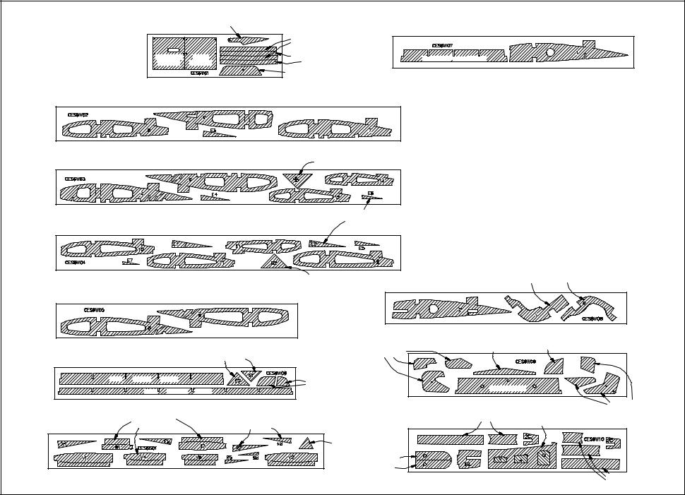
DIE-CUT PATTERNS
CES6F01 |
|
2 REQ. |
CABIN SIDE |
3/32" X 3" X 18" |
BALSA |
TOP |
|
|
HORIZONTAL STAB
RIBS “S’s”
CES6F02 |
|
|
2 REQ. |
|
|
|
|
DORSAL FIN |
|
|
|
|
FORMERS |
|
|
3/32" X 3" X 21" |
BALSA |
CABIN SIDE |
|
|
|
|
BOTTOM |
|
|
FIREWALL |
WINDOW |
|
|
CES6F03 |
FRAME |
2 REQ. |
||
SIDE SUPPORTS |
||||
|
||||
|
|
|
SERVO |
|
|
|
|
TRAY |
1/8" X 6-5/8" X 19" |
PLY |
CES6F04 |
1 REQ. |
|
NOSE GEAR |
|
DOUBLER |
1/8" X 6-5/8" X 19" |
PLY |
CES6S02 |
1 REQ. |
STAB TE |
|
|
STAB TE |
FIN TE |
|
1/4" X 2-3/4" X 15" |
BALSA |
CES6F05 |
INSTRUMENT PANEL |
1 REQ. |
FIN DRILL |
1/8" X 5-3/4" X 19" PLY |
|
GUIDE |
|
|
|
|
CES6F06 |
1 REQ. |
1/8" X 5-3/4" X 19" |
PLY |
CES6F07 |
1 REQ. |
TANK ROOF |
|
1/8" X 5-3/4" X 19" |
PLY |
CES6F08 |
STAB |
2 REQ. |
SADDLE |
||
|
|
FUSE KEEL |
|
WING SADDLE BRACE |
HORN |
|
|
|
|
|
REINFORCEMENT |
|
1/8" X 5-3/4" X 19" |
PLY |
7
|
|
|
|
|
DIE-CUT PATTERNS |
|
|
|
|
|
|
||
|
|
|
FLAP HORN |
|
|
CES6W07 |
|
|
|
|
1 REQ. |
||
|
CES6W01 |
2 REQ. |
UPPER SPAR |
|
|
|
|
||||||
|
|
|
|
|
|
|
|
|
|
|
|
|
|
|
|
|
|
|
|
JOINER |
|
|
|
|
|
|
|
|
|
AILERON |
FLAP |
|
|
LOWER SPAR |
|
CENTER AFT SPAR |
|
|
|
|
|
|
|
|
|
JOINER |
|
|
|
|
|
||||
|
|
HATCH |
HATCH |
|
|
|
|
|
|
|
|
|
|
|
|
|
|
|
|
MAIN WHEEL PANT |
|
1/8" X 2-3/4" X 21" |
BALSA |
|
|||
|
1/16" X 3-3/4" X 11-3/4" |
PLY |
AXLE SUPPORT |
|
|
||||||||
|
|
|
|
|
|
|
|
||||||
CES6W02 |
|
|
|
|
|
|
2 REQ. |
|
|
|
|
|
|
|
|
3/32" X 3" X 30" |
BALSA |
STAB |
|
|
|
|
|
|
|
||
CES6W03 |
|
|
|
|
|
2 REQ. |
|
|
|
|
|
|
|
|
|
|
|
|
GUSSET |
|
|
|
|
|
|
||
|
|
|
|
|
|
|
|
|
|
|
|
||
|
|
3/32" X 3" X 30" |
BALSA |
ELEVATOR |
|
|
|
|
|
|
|||
CES6W04 |
|
|
|
|
|
RIBS “E’s” |
|
|
|
|
|
|
|
|
|
|
|
|
|
2 REQ. |
|
|
|
|
|
|
|
|
|
3/32" X 3" X 30" |
BALSA |
GUSSET |
|
|
|
|
COWL RING |
|
|||
|
|
CES6W08 |
|
TOP |
|
BOTTOM |
2 REQ. |
||||||
CES6W05 |
|
|
|
|
|
|
|
|
|
|
|||
|
|
|
|
|
|
|
|
|
|
|
|
|
|
|
|
|
|
|
|
|
|
1/8" X 2-3/4" X 21" |
BALSA |
|
|||
|
3/32" X 3" X 21" BALSA |
|
|
FLAP DRILL |
CES6W09 |
STAB |
DIHEDRAL |
1 REQ. |
|||||
|
|
|
|
GAUGE |
|||||||||
|
|
|
GUIDE PARTS |
JOINER (SJ) |
|
||||||||
CES6W06 |
|
|
GUSSETS |
2 REQ. |
|
|
|
|
|
|
|
||
|
|
|
|
|
|
|
|
|
|
|
|||
AFT |
INNER |
SPAR |
|
|
|
MAIN WHEEL |
|
|
|
|
|
|
|
|
|
|
|
|
|
|
|
CENTER LE |
|
|
|
|
|
|
AFT |
OUTER |
SPAR |
|
|
PANT SPACERS |
|
|
|
|
|
|
|
|
|
|
|
|
|
|
|
|
|
||||
1/8" X 2-3/4" X 21" BALSA |
|
|
|
1/8" X 3-3/4" X 19" |
PLY |
FLAP DRILL |
|||||||
|
|
|
GUIDE PARTS |
||||||||||
|
VERTICAL FIN |
|
RUDDER |
|
|
CES6W10 |
OUTER DIHEDRAL |
WING JIG |
|
|
|||
|
|
|
|
BRACE PARTS |
|
2 REQ. |
|||||||
CES6S01 |
RIBS “V’s” |
|
RIBS “R’s” |
1 REQ. |
|
|
PARTS |
|
|||||
|
|
|
|
|
|
||||||||
|
|
|
|
|
|
|
|
|
|
|
|
||
|
|
|
|
|
|
FIN |
|
|
|
|
|
|
|
|
|
|
|
|
|
GUSSET |
|
|
|
|
|
|
|
|
|
|
|
|
|
|
WING BOLT |
|
|
|
|
|
|
|
3/32" X 3" X 24" BALSA |
|
|
PLATES |
|
|
|
|
|
|
|||
|
|
|
|
1/8" X 3-3/4" X 19" |
PLY |
POLYHEDRAL |
|||||||
|
|
|
|
BRACE PARTS |
|||||||||
|
|
|
|
|
|
|
|
||||||
|
|
|
|
|
|
8 |
|
|
|
|
|
|
|

Get ready to build
1.Unroll the plan sheets. Re-roll the plans inside-out to make them lie flat.
2.Remove all parts from the box. As you do, figure out the name of each part by comparing it with the plans and the parts list included with this kit. Using a felt tip or ball point pen, lightly write the part name or size on each piece to avoid confusion later. Use the die-cut patterns shown on pages 7 and 8 to identify the die-cut parts and mark them before removing them from the sheet. Save all scraps. If any of the die-cut parts are difficult to punch out, do not force them! Instead, cut around the parts with a hobby knife. After punching out the die-cut parts, use your T- Bar or sanding block to lightly sand the edges to remove any die-cutting irregularities.
3.As you identify and mark the parts, separate them into groups, such as fuse (fuselage), wing, fin, stab (stabilizer), and hardware.
Zipper-top food storage bags are a handy way to store your small parts as you sort, identify, and separate them into sub-assemblies.
BUILD THE TAIL SURFACES
Build the horizontal stabilizer
1. Work on a flat surface over the plans covered with waxed paper. Refer to the plans to identify the parts and their locations. The plans may be cut apart if space is a problem.
2.Punch out both sets of the die-cut 3/32” balsa ribs S-1 through S-7. There is a jig tab on the bottom edge of each of these ribs. If any of these break off, carefully glue them back on with a drop of thin CA. Lightly sand any imperfections. You may need to finish cutting the notch in the forward portion of S-1 for the Stab Joiner (SJ) with a knife. Use a pen to mark the extensions of the bottom edge of the ribs across the fore and aft ends of the jig tabs. These marks will help when you trim off the jig tabs later.
3.The stab Trailing Edges (S) are die-cut from 1/4” balsa. Since some crushing may occur during die-cutting wood of this thickness, they are supplied slightly long and can be trimmed. True up all edges of these pieces with a T-bar.
 FIN / STAB LE
4. Cut the stab Leading Edges (LE’s) to length from the 1/4” x 15” tapered balsa stock.
They should be about 1/4” longer than the length shown on the plans for the stab LE.
5. Center the 1/2” x 5/8” x 9-3/4” balsa TE Center Brace over the plans and pin it in place. Use a triangle and pen to mark the inboard ends of the Stab TE. Remove the TE Center Brace from the building board.
6. Apply thick CA to one half of the TE Center Brace, then align the inboard end of a Stab TE with the reference line you just drew. Glue the TE Center Brace in position. The TE
Center Brace must be centered on the Stab TE. Repeat this operation for the other half of the TE, then use long T-pins to pin the assembly over the plans.
NOTE: Position the outboard ends of the TE about 1/2” above the board. The TE Center Brace should be raised about 3/8”. (See next photo.)
9
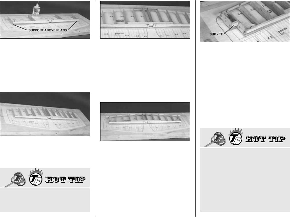
7. Pin the left and right S-3 and S-6 ribs to the building board over their locations on the plans. Adjust the height of the Stab TE to align it evenly with the aft edge of the ribs. Glue the ribs to the Stab TE and to the TE Center Brace with thin CA.
8. Align and glue all of the remaining Stab ribs to the TE.
Lightly sand a bevel along the front edge of the Stab ribs to match the sweep angle of the LE. This will give you a better fit and a stronger glue joint.
9. Glue the two die-cut 3/32” balsa Stab Gussets into the junction of S-6 and the Stab TE. The Gussets should be centered between the top and bottom of the ribs and Stab TE. Glue the die-cut 1/8” ply Forward Stab Brace into the slots in the S-1 ribs and to the inside edges of the S-2 ribs.
10. Sand one end of two shaped balsa Stab LE’s to exactly match the angle at the center of the Stab. Leave the outboard ends long for the time being. Center the LE (vertically) on the front of the ribs, then tack glue the Stab LE’s to the forward edge of ribs S-1 and S-6 and to the Forward Stab Brace (this will align the LE). Glue the remaining ribs to the LE, checking for straightness as you proceed.
11. Glue both S-7 ribs to the Stab LE.
12. Glue the 1/4” x 1/2” x 7/8” balsa Stab Sub TE to the aft edge of S-7 and to the side of S-6. Make sure that the Stab Sub TE is positioned exactly 90 degrees to S-6.
13. Trim the Stab LE’s flush with the S-7’s.
Reinforce all of the joints with medium CA.
Sand the tips of the LE, sub TE, and TE flush with S-7 and S-6.
14. Remove the pins, then lightly sand the top surface of the stab frame to blend all parts and remove any excess CA. Take care not to change the shape of the airfoil.
HOW TO MAKE WING AND STAB SKINS
A.Wherever practical, pre-join the balsa sheets to make a “skin” before attaching them to the structure.
B.Many modelers like to sort the wood so they can put the best wood with the most even grain structure on the top of the wing and stab.
C.Make your skin larger than needed to allow
10
for misalignment. On a large surface such as the wing, 3/8” extra is suggested.
D. To make skins, the following steps are suggested:
1.True up the edges of the sheets with a metal straightedge and a sharp knife or a “T-Bar” sanding block.
2.Test-fit the sheets together to make sure they match well.
3.METHOD “A”: Edge glue the sheets together with thin CA, over a flat surface covered with waxed paper. A quick wipe of the joint with a fresh paper towel will remove excess glue and make sanding easier. Mark the poorest surface to identify it as the “inside” surface.
METHOD “B”: Edge glue the sheets together with Titebond® wood glue. (Titebond is easier to sand and won’t leave a ridge at the seam, as CA is prone to do.) Smear the glue lightly along an edge with your finger, then join the sheets over a flat (waxed paper covered) building board. Pin the sheets to the board to hold them together. Wipe off any excess glue before it dries.
4.Place the skin on a large flat surface and sand it with a large flat sanding block and fresh, sharp 220 paper. Use light pressure and a brisk circular motion.
5.Trim the perimeter of the sheet to even things out.
13" |
12-1/8" |
|
STAB SKIN |
STAB SKIN |
3" |
|
||
12-1/8" |
13" |
|
15. Make two 6”x 30” stab skin planks from four 1/16” x 3” x 30” balsa sheets. From these planks, cut four stab skins. See the sketch for the proper layout on the wood. Refer to the plans for the exact shapes and sizes, but remember to make the skins slightly oversize.
16. Pin the stab structure to your building surface using pins only at the tips and diagonally under the LE & TE. Make sure that the jig tabs are flat on the building surface. Don’t hide the pins under the skin.
17. Use the off-cut 1/16” material from the skin planks to make a 1” wide cross-grain strip to fit between the S-1’s from the LE to the TE. Glue the strip in place between the ribs, flush with the top edge.
18. Test-fit the skins over the stab frame. Make sure the skins meet flush at the center. Adjust them with a sanding block if necessary. Apply an even bead of medium or thick CA to the upward-facing edges on one side of the frame. Place a skin in its proper position and press it firmly down until the glue has set. Repeat this step for the other top skin. Trim off the excess balsa, but save any big scraps for use when making the elevators.
19. Remove the stab from the building board. Trim off the jig tabs with a sharp knife. Trim and blend the LE and TE to the ribs as you did before. Check all glue joints, adding glue as necessary.
20. Cut another 1” wide cross-grain strip from 1/16” x 6” off-cut balsa sheeting and glue it between the two S-1 ribs flush with their bottom edges.
21. It’s important to get a good glue bond between the stab frame and the bottom stab skins. Apply a heavy bead of medium or thick
11
CA to all of the upward facing edges on one side of the stab frame. Place a skin on the frame and hold it in place with your hands until the glue sets. Repeat this for the other bottom skin. Be careful not to bend or twist the stab during this step.
22. Trim off the excess balsa from around the perimeter of the stab. True up the ends of the stab with a sanding block. Round the LE of the stab to match the cross section on the plan.
Build the elevators
15"
ELEVATOR SKIN
3"
SCRAP
1. Cut two 1/16” x 3” x 36” balsa sheets to make four 15” long sheets. Refer to the sketch and the elevator plans, then glue the leftover balsa “wedges” that you cut from the stab skins to the 15” sheets. These joined sheets will be used to make the top and bottom Elevator skins.
2. Use the pattern on the plans to cut four Elevator skins. Sort the skins so that the best surfaces will be facing outward, and on the top.
3. Cover the elevator plan with waxed paper, then pin a skin in position. Use the “tic” marks on the plan to draw the rib locations on the skin.
 3/8"
3/8"

 1/32"
1/32"
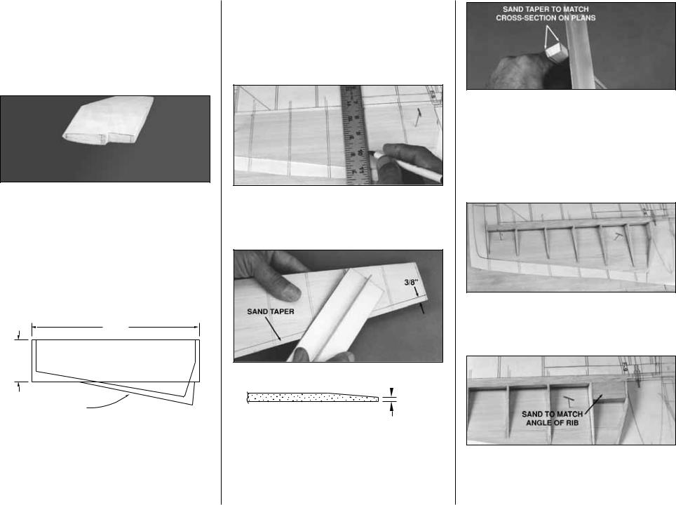
4. Draw a line along the length of the skin’s TE 3/8” in from the edge. Remove the skin from the building board, then holding it along the edge of your work bench, sand a taper from the line towards the TE so that the TE will be approximately 1/32” thick.
5. Locate the 3/8” x 3/4” x 11-5/8” shaped balsa Elevator LE. Draw two lines, 1/32” in from each edge, on one side of the LE as shown in the photo. Use the lines as a reference to taper the top and bottom of the LE toward the elevator TE with a T-bar sander. Proceed carefully, checking your progress against the height of the elevator ribs at each location.
6. Glue the LE to the inside surface of the the elevator skin, flush with the forward edge of the skin. Glue the 3/32” die-cut balsa ribs (E-1 through E-7) to the skin and to the LE with thin CA.
7. Test fit a 1/2” x 1” x 1-5/8” balsa Torque Rod block between ribs E-1 and E-2. Sand the ends, if necessary, for a good fit. Sand a slight angle on the forward edge of the Torque Rod
12
block (the one that will contact the elevator’s LE) to match the angle of the LE. Glue the Torque Rod block in position when you are satisfied with the fit.
8. Carefully sand the top of the Torque Rod block flush with the taper of the ribs.
9. Mark and sand the inside TE of an elevator skin as you did in step 4. Apply a bead of thick CA to LE, TE, and all ribs, then glue the top skin into position. Hold the assembly flat until the CA cures.
10. True up all edges with a T-bar or sanding block.
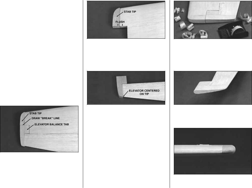
11. Test fit the Stab, Elevator, 5/8” x 7/8” x 6-1/2” shaped balsa Stab Tip, and the 5/8” x 27/32” x 1-9/16” balsa Elevator Balance Tab together. Make any adjustments with light sanding. Mark the “break”between the Stab and the Elevator on the Stab Tip. Cut the Stab Tip apart along this line.
12. Glue the forward balsa Stab Tips in position.
13. Glue the Elevator Balance Tab flush with the Elevator Tip. Center the Stab Tip on the outboard end of the Elevator, before using thick CA to glue in place. Make sure that both the Elevator LE and TE are centered before the CA cures.
14. Tape the elevator assembly to the Stab. Make sure that the Stab Tip and Elevator Balance Tab are flush along the outside edge. There should be a 1/32”-1/16” gap between the Elevator Balance Tab and the Stab. If not, use your T-bar sander to correct the problem by alternately sanding the inside edges of the Elevator Balance Tab and the Stab.
15. When satisfied with the fit, use a razor plane and sanding block to shape the Stab Tip to blend with the Elevator and Stab.
16. Sand a radius around the Balance Tab as shown in the photo.
17. Sand a radius around the outboard edges of the Stab and Elevator Tip.
13

18. Tape the Elevators to the Stab making sure that you have the correct clearance around the Balance Tabs. Hold the bent 1/8” Elevator Joiner Wire and Horn up to the Elevator and mark the location of the Joiner Wire holes that will be perpendicular to the hinge line (see the plans for the joiner location).
NOTE: The Elevator Horn is off-center. When looking at the top surface of the Stab, the Horn will be to the right of Stab center.
19. Drill 9/64” holes in the elevators for the Joiner wire. Cut slots inboard of the holes to allow the wire to be inset into the elevators, flush with the LE. Sand the Elevator LE to a “V” shape to allow for Elevator travel — refer to the plans for the correct angle.
20. Test-fit, but do not glue the joiner wire into the Elevators. Check to see that the Elevators align with each other properly and that they fit the Stab without binding. Make adjustments by removing the Joiner Wire and then bending it, if required.
Build the fin
1. Cover the Fin/Rudder section of the plans with waxed paper.
2. Punch out the die-cut 3/32” balsa ribs V-1 through V-6. Be sure to preserve their jig tabs.
NOTE: If you plan to install an operational beacon light on top of the Fin drill a 3/16” hole through the center (front to back, top to bottom) of each rib. This hole will provide a passage for the wiring.
3. Cut a 15” length of the tapered 1/4” balsa
Stabilizer/Fin LE stock to match the plans exactly, as the length of the LE sets the angle of the fin. Notice that the Fin LE fits into a notch on top of F-8.
4. Punch out the die-cut 1/4” balsa Fin TE and lightly sand the edges to touch them up. Sand (or cut) the tips to match the sweep angle as shown on the plans.
5. Sand an angle on the ends of each rib to match the sweep angle of the LE and TE. Pin ribs V-1 and V-6 to the building board over their proper locations. Center the LE on the front of the ribs and glue it in place. Center the Fin TE on the aft edge of the ribs and glue it in place.
6. Put ribs V-2 through V-5 into their places and glue them to the LE and TE. Remember, all jig tabs should contact the work surface.
7. Glue the die-cut 3/32” balsa Fin Gusset into the corner of V-6 and the Trailing Edge.
8. Apply extra CA+ glue to any joints that do not appear to be well glued.
9. Blend the LE to match the ribs on the upward facing (left) fin side. Sand the TE, if necessary, to blend smoothly with the ribs.
30"
3"
FIN SKIN
10. Make a skin for each side of the fin using 1/16” x 3” x 30” balsa sheet. Leave excess balsa on one edge of the skin so it overhangs past V-1 about 5/8”; this will allow fitting to the stab later. With the structure flat on the table, glue on the left (upward-facing) skin.
14

11. Remove the fin from the building board and trim off the jig tabs. Blend the LE and TE to the ribs on the right side of the fin.
NOTE: If you plan to route wiring for a beacon through the fin, install a 15” length of outer pushrod tube (not supplied) through the 3/16” holes you drilled in step #2. Glue it in position with medium CA, leaving the excess tube protruding from V-1.
12. Use medium or thick CA to glue on the right side skin. Be sure to get a good bond between the ribs and the skin.
13. True up the edges of the fin sheeting with a sanding block. Shape the LE to match the cross section on the plans. Don’t trim the bottom edge of the sheeting at this time.
14. Glue the shaped 3/4” balsa Fin Tip to the top of the fin. Shaping should be done later, with the fin taped to the rudder.
NOTE: If adding a beacon light, drill a hole through the top of the Fin Tip that aligns with the wiring tube before you glue it in place.
Build the rudder
30"
3"
EXCESS
1. Use one 1/16” x 3” x 30 balsa sheet to make two rudder skins, using the rudder skin pattern on the wing plan. You will need to edge glue a small wedge shaped piece of sheeting to the TE of the skin to provide the correct width.
You should have more than enough material left over from the previous assemblies to accomplish this step.
2. Pin one of the rudder skins to the (wax paper covered) plans and draw the location of each rib using the “tic” marks as a guide. Draw a line the length of the rudder skin, 3/8” in from the aft edge, as you did with the elevators. Remove the rudder skin from the board and taper the aft edge to 1/32”. Taper the aft edge of the other rudder skin to 1/32”. (See next photo.)
3. Locate the 3/8” x 3/4” x 12” tapered balsa rudder LE. Cut the tips to match the sweep
angle of the rudder. Lightly sand both sides of the rudder LE to match the angle toward the aft edge of the rudder.
4. Re-pin the rudder skin over the plans. Glue the rudder LE to the surface of the rudder skin, flush with the front edge, using medium CA. The wide end of the rudder LE is at the bottom end of the rudder.
5. Slightly taper the forward edge of the rudder ribs R-1 through R-6 to match the sweep angle of the rudder LE, then glue them in position over the location lines that you drew in step #2.
6. Shape one end of the 1/4” x 1/2” x 1-1/4” balsa rudder Torque Block to match the angle at the intersection of the rudder LE and R-1. Glue the Torque Block in position when satisfied with the fit.
7. Remove the rudder assembly from the board, then lightly sand the frame to blend all joints. Glue the second rudder skin to the frame with thick CA. To prevent twists, be sure that the assembly is held on a flat surface while the CA cures.
15
8. True up all rudder edges with a sanding block.
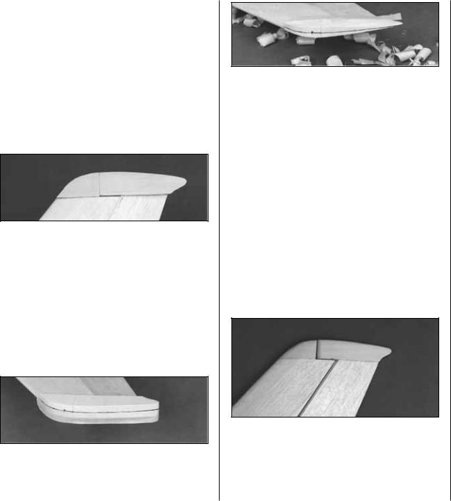
9. Position the rudder against the TE of the fin with the top of the rudder 1/32” above the top of the main body of the fin. Tape the fin and rudder securely together with masking tape.
NOTE: Before proceeding, study the photo at step 15 to see what you will accomplish in the next six steps.
10. Test fit the 3/4” shaped balsa Rudder Tip on top of the rudder. It should butt against the Fin Tip squarely, and have a clearance gap of 1/32” above the fin. Make adjustments with a sanding block if needed.
11. Use thick CA to glue the Rudder Tip to the rudder. Be sure that everything is centered before the CA cures.
12. Draw a center reference line across the top of the rudder and fin blocks. A piece of masking tape stretched across the center of the blocks will help you draw a fairly straight line.
13. Use a razor plane and sanding block to shape the top of the fin and rudder. For scale realism, the Rudder Tip should be slightly wider than the rudder. Apply 4 layers of masking tape to each side of the rudder to prevent you from removing too much material. The Fin Tip may be sanded flush with the fin. Round off the top 3/8” of both the Fin and Rudder Tips. When the top is shaped and sanded, remove all masking tape.
14. Draw a centerline on the rudder’s LE. Sand a “V” bevel along this line with reference to the plans for the correct angle. Hinging and installation of the torque rod will come later in the assembly process.
15. Sand a radius around the forward edge of the Rudder Tip. Hold the fin and rudder together to check the clearance between the Rudder Tip and the Fin Tip. Continue sanding the Rudder Tip radius until there is a 1/32” gap between the two parts.
Okay, the tail feathers are more or less complete, so by now you are on a roll. The stab looks like the wing for a .20-size model, doesn’t it? We’ll build the wing next so you’ll really have something to impress your buddies when they drop in to see “how the ol’ Cessna is doing.”
BUILD THE WING
NOTE: The wing panels are built “UPSIDEDOWN” on the plans. The jig tabs are attached to what is, in the end, the TOP surface of the wing. Since it is the standard convention to show the Top View of the wing, and the wing panels are built upside-down, the LEFT wing panel is built over the RIGHT Wing Top View and vice-versa. This does not present any problems — just be sure to build a left and a right wing.
Build the center section
1. Punch out all the die-cut 3/32” and 1/8” balsa wing Ribs. Smooth out any imperfections with sandpaper. Be sure to keep the jig tabs attached to the ribs.
2. Punch out the 1/8” ply Doublers and Wing Bolt Plates.
16

3. Lay out both sets of balsa Ribs W-2 and W- 3, ply Doublers W-2B and W-2C, and the ply Wing Bolt Plates exactly as shown in the photo.
This way you won’t assemble two right or two left sides. Glue the Doublers to the Ribs and laminate the two pairs of Wing Bolt Plates with 30-Minute Epoxy. After the epoxy has cured, test fit the Wing Bolt Plates into the slots at the aft end of W-2 and W-3. Make slight adjustments to the slots if required, but don’t make the fit too loose as this is a critical area for a nice tight bond.
4. Attach the wing plan (the part showing the center section) to a flat building board and cover it with waxed paper. Cutting apart the wing panel sections of the plan makes handling easier.
5. Locate the 3/8” x 3/8” x 20” basswood Center Spar. Cut two 9-1/4” pieces from it. Pin one of the 3/8” x 3/8” x 9-1/4” basswood Center
Spars to the plan using the method shown in the sketch. The Center Spar is a little longer than actually needed to allow for the dihedral angle at W-3. It will be trimmed to size later.
NOTE: Do not use any CA until step 11.
6. Position rib W-1 and rib assemblies W-2 and W-3 on the Center Spar with the jig tabs touching the plan. Be sure that the ply doublers are facing the correct direction.
7. Insert (without gluing) the die-cut 1/8” balsa Center Aft Spar into the slots above the jig tabs. Insert the second basswood Center Spar into the forward rib notches. Make sure that both Spars are flush with the upper edge of the ribs.
8. Interlock the 1/8” die-cut ply Center LE with the tabs on the LE of ribs W-3 and W-1.
9. Study the structure. Are all parts over their respective locations on the plans and in alignment? If not, lightly use fine grit sandpaper to adjust the fit. Don’t reach for the CA yet!
10. Make sure the W-3 ribs are flush with the Aft Spar and the Center LE. Use the 1/8” die-cut ply Dihedral Gauge on the inside of the W-3 ribs at the forward Spars to set the ribs angle at this location. Hold a straightedge alongside the W-3’s to check for straightness.
11. When you are sure that everything is straight and true (sight down the TE and shim any low ribs with folded paper under the jig tabs) wick thin CA into every joint. Hold the LE and W-3’s in tight contact for a few seconds to allow the CA to work. Follow the initial gluing by applying a fillet of medium CA around the joints.
Isn’t interlocking construction great?!
17
 Loading...