


|
|
|
|
|
|
® |
|
|
|
|
|
|
|
|
® |
|
|
|
|
™ |
|
|
|
|
|
|
|
|
|
|
|
|
|
|
|
|
|
Wingspan: 81 in [2060mm] |
Wing Loading: 30 – 32 oz/ft2 [92 – 98g/dm2] |
Engine: .60 – .91 cu in [10 – 15cc] two-stroke, |
|
|||
|
|
Wing Area: 898 sq in [57.9 dm2] |
Length: 64 in [1630mm] |
.91 – 1.20 cu in [15 – 20cc] four-stroke, |
|
|||
|
|
Weight: 11.5 – 12.5 lb [5220 – 5670g] |
Radio: 5+ channel with 6 – 7 servos |
Motor: RimFire™ 1.20 (50-65-450kV) Out-Runner Motor |
|
|||
|
|
|
|
|
|
|
||
|
|
WARRANTY.....Top Flite® Models guarantees this kit to be free |
the buyer is advised to return this kit immediately in new and unused condition to the place |
|
|
|||
|
|
from defects in both material and workmanship at the date of purchase. This warranty does |
If the buyer is not prepared to accept the liability associated with the use of this product, |
|
|
|||
|
|
of purchase. |
|
Hobby Services |
|
|
||
|
|
not cover any component parts damaged by use or modification. In no case shall Top Flite’s |
To make a warranty claim send the defective part or |
|
|
|||
|
|
liability exceed the original cost of the purchased kit. Further, Top Flite reserves the right to |
3002 N. Apollo Dr., Suite 1 |
|
|
|||
|
|
change or modify this warranty without notice. |
|
item to Hobby Services at the address: |
Champaign, IL 61822 USA |
|
|
|
|
|
In that Top Flite has no control over the final assembly or material used for final assembly, no |
Include a letter stating your name, return shipping address, as much contact information as |
|
|
|||
|
|
liability shall be assumed nor accepted for any damage resulting from the use by the user of |
possible (daytime telephone number, fax number, e-mail address), a detailed description of the |
|
|
|||
|
|
the final user-assembled product. By the act of using the user-assembled product, the user |
problem and a photocopy of the purchase receipt. Upon receipt of the package the problem will |
|
|
|||
|
|
accepts all resulting liability. |
|
be evaluated as quickly as possible. |
|
|
|
|
|
|
|
|
|
|
|
|
|
|
|
|
|
|
|
|
|
|
|
|
READ THROUGH THIS MANUAL BEFORE STARTING CONSTRUCTION. IT CONTAINS IMPORTANT INSTRUCTIONS AND WARNINGS CONCERNING THE ASSEMBLY AND USE OF THIS MODEL. |
|
|
||||
|
Top Flite Models Champaign, IL |
Telephone (217) 398-8970, Ext. 5 |
|
airsupport@top-flite.com |
|
|||
|
|
|
|
|
|
|
|
|
|
|
|
|
|
|
|
|
|
|
|
|
|
|
|
|
|
|
Entire Contents © Copyright 2009 |
TOPA0906MNL V1.0 |

TABLE OF CONTENTS |
|
|
Balance the Model (C.G.) . . . . . . . . |
. 32 |
|
|
|
||||
|
|
|
Balance the Model Laterally . . . . . . . |
. 33 |
|
INTRODUCTION . . . . . . . . . . . . |
. |
2 |
PREFLIGHT . . . . . . . . . . . . . . 33 |
||
AMA . . . . . . . . . . . . . . . . |
. |
. 2 |
Identify Your Model . . . . . . . . . . . |
33 |
|
SAFETY PRECAUTIONS . . . . . . . . |
. |
. 2 |
Charge the Batteries . . . . . . . . . . |
33 |
|
DECISIONS YOU MUST MAKE . . . . . . |
. |
3 |
Balance Propellers . . . . . . . . . . . |
33 |
|
Building Stand . . . . . . . . . . . . |
. |
3 |
Range Check . . . . . . . . . . . . . |
33 |
|
Radio Equipment . . . . . . . . . . . |
. |
3 |
ENGINE SAFETY PRECAUTIONS . . . . . |
. 33 |
|
Engine Recommendations . . . . . . . |
. |
. 3 |
AMA SAFETY CODE (excerpts) . . . . . . |
34 |
|
Scale Competition . . . . . . . . . . |
. |
. 4 |
General . . . . . . . . . . . . . . . . 34 |
||
ADDITIONAL ITEMS REQUIRED . . . . . |
. |
4 |
Radio Control . . . . . . . . . . . . . |
34 |
|
Hardware & Accessories . . . . . . . . |
. |
4 |
CHECK LIST . . . . . . . . . . . . . . 34 |
||
Adhesives & Building Supplies . . . . . . |
. |
4 |
FLYING . . . . . . . . . . . . . . . . 35 |
||
Optional Supplies & Tools . . . . . . . . . . . . . . . |
. . . 4 |
Fuel Mixture Adjustments . . . . . . . . |
. 35 |
||
IMPORTANT BUILDING NOTES . . . . . |
. |
. 5 |
Takeoff . . . . . . . . . . . . . . . . 35 |
||
ORDERING REPLACEMENT PARTS . . . . |
. |
5 |
Flying . . . . . . . . . . . . . . . . 35 |
||
Replacement Parts List . . . . . . . . |
. |
. 5 |
Landing . . . . . . . . . . . . . . . . . . . . . . . . . . . . . . . 35 |
||
KIT INSPECTION . . . . . . . . . . . |
. |
. 5 |
Flaps . . . . . . . . . . . . . . . . . . . . . . . . . . . . . . . . . 35 |
||
Kit Contents . . . . . . . . . . . . . |
. |
7 |
|
|
|
PREPARATIONS . . . . . . . . . . . . |
. |
7 |
INTRODUCTION |
|
|
ASSEMBLE THE WING . . . . . . . . . |
. |
7 |
|
||
Hinge the Ailerons And Flaps . . . . . . |
. |
. 7 |
Congratulations on your purchase of the Top Flite |
||
Install the Aileron Servo & Linkage . . . . |
. |
9 |
|||
Cessna 182 ARF! The Cessna 182 ARF is built using |
|||||
Install the Flap Servo & Linkage . . . . . |
. 11 |
||||
virtually the same airframe as the very successful |
|||||
Finish the Wing . . . . . . . . . . . . |
. 12 |
||||
Top Flite Cessna kit. With the time consuming tasks |
|||||
INSTALL THE TAIL, LANDING GEAR & SERVOS |
. |
13 |
|||
of building, covering, and painting already done for |
|||||
Install the Horizontal Stabilizer, |
|
|
|||
|
|
you, you can be flying your scale Cessna after as |
|||
Elevators & Rudder . . . . . . . . . |
. |
13 |
|||
little as 15 to 20 hours of assembly! A pre-painted |
|||||
Install the Landing Gear . . . . . . . . |
. |
15 |
|||
ABS cockpit kit is included for added realism. The |
|||||
Install the Tail Servos & Pushrods . . . . |
. |
16 |
|||
corrugated control surfaces, functional pre-installed |
|||||
INSTALL THE POWER SYSTEM . . . . . |
. |
19 |
|||
flying lights, and generous use of fiberglass are details |
|||||
Glow Engine Installation . . . . . . . . |
. |
19 |
|||
you typically won’t find in other scale ARF planes. |
|||||
Brushless Motor Installation . . . . . . . |
. 22 |
||||
Although the Cessna 182 ARF already includes an |
|||||
FINISH THE MODEL . . . . . . . . . . |
. |
22 |
|||
impressive list of these “extras” right out of the box, |
|||||
Install the Receiver & Batteries . . . . . |
. |
22 |
|||
the sky is the limit for the amount of additional scale |
|||||
Install the Cowl . . . . . . . . . . . . |
. 24 |
||||
detail you can create while assembling the Cessna to |
|||||
Install the Cockpit Windows . . . . . . . |
. 25 |
||||
be truly admired at the flying field or in competition. |
|||||
Install the Cockpit Kit . . . . . . . . . |
. |
26 |
|||
|
|
||||
Install the Spinner & Propeller . . . . . . |
. 29 |
Because of its 81" wingspan, the Top Flite Cessna 182 |
|||
Final Touches . . . . . . . . . . . . |
. |
29 |
|||
ARF is eligible to be entered at IMAA events. In order |
|||||
Apply the Decals . . . . . . . . . . . |
. 30 |
||||
to be IMAA-legal, some of the control components |
|||||
GET THE MODEL READY TO FLY . . . . . |
. 30 |
||||
and hardware may need to be replaced to conform |
|||||
Install & Connect the Motor Battery . . . . |
. 30 |
||||
to Giant Scale rules even though this model does not |
|||||
Check the Control Directions . . . . . . |
. |
31 |
|||
require heavy duty hookups. |
|
||||
Set the Control Throws . . . . . . . . . |
. 31 |
|
|||
|
|
||||
For the latest technical updates or manual corrections to the Cessna 182 ARF visit the Top Flite web site at www.top-flite.com. Open the “Airplanes” link, then select the Cessna 182 ARF. If there is new technical information or changes to this model, a “tech notice” box will appear in the upper left corner of the page.
AMA
If you are not already a member of the AMA, please join! The AMA is the governing body of model aviation and membership provides liability insurance coverage, protects modelers’ rights and interests and is required to fly at most R/C sites.
Academy of Model Aeronautics
5151 East Memorial Drive Muncie, IN 47302-9252
Tele. (800) 435-9262 Fax (765) 741-0057 Or via the Internet at:
http://www.modelaircraft.org
IMPORTANT!!! Two of the most important things you can do to preserve the radio controlled aircraft hobby are to avoid flying near full-scale aircraft and avoid flying near or over groups of people.
PROTECT YOUR MODEL,
YOURSELF & OTHERS.....FOLLOW THESE IMPORTANT SAFETY PRECAUTIONS
1.Your Cessna 182 ARF should not be considered a toy, but rather a sophisticated, working model that functions very much like a full-size airplane. Because of its performance capabilities, the Cessna, if not assembled and operated correctly, could possibly cause injury to yourself or spectators and damage to property.
2.You must assemble the model according to the instructions. Do not alter or modify the model, as
doing so may result in an unsafe or unflyable model. In a few cases the instructions may differ slightly from the photos. In those instances the written instructions should be considered as correct.
2

3. You must take time to build straight, true and strong.
4.You must use an R/C radio system that is in good condition, a correctly sized engine, and other components as specified in this instruction manual. All components must be correctly installed so that the model operates correctly on the ground and in the air. You must check the operation of the model and all components before every flight.
5.If you are not an experienced pilot or have not flown this type of model before, we recommend that you get the assistance of an experienced pilot in your R/C club for your first flights. If you’re not a member of a club, your local hobby shop has information about clubs in your area whose membership includes experienced pilots.
6.While this kit has been flight tested to exceed normal use, if the plane will be used for extremely high stress flying, such as racing, or if an engine larger than one in the recommended range is used, the modeler is responsible for taking steps to reinforce the high stress points and/or substituting hardware more suitable for the increased stress.
7.WARNING: The cowl, wheel pants, wing struts, tail cone, wing tips and landing gear legs included in this kit are made of fiberglass, the fibers of which may cause eye, skin and respiratory tract irritation. Never blow into a part (wheel pant, cowl) to remove fiberglass dust, as the dust will blow back into your eyes. Always wear safety goggles, a particle mask and rubber gloves when grinding, drilling and sanding fiberglass parts. Vacuum the parts and the work area thoroughly after working with fiberglass parts.
We, as the kit manufacturer, provide you with a top quality, thoroughly tested kit and instructions, but ultimately the quality and flyability of your finished model depends on how you build it; therefore, we cannot in any way guarantee the performance of your completed model, and no representations are expressed or implied as to the performance or safety of your completed model.
Remember: Take your time and follow the instructions to end up with a well-built model that is straight and true.
DECISIONS YOU MUST MAKE
This is a partial list of items required to finish the Cessna 182 ARF that may require planning or decision making before starting to build. Order numbers are provided in parentheses.
Building Stand
A building stand or cradle comes in very handy during the build. We use the Robart Super Stand II (ROBP1402) for most of our projects in R&D, and it can be seen in pictures throughout this manual.
RADIO EQUIPMENT
A 6-channel radio system such as a Futaba® 6EXAS with a standard receiver and six standard size servos with a minimum torque of 44 oz-in [3.2 kg-cm] are required for the control surfaces of the Cessna 182 ARF.
One standard torque servo such as an S3003 is required for the throttle. Two 24" [610mm] servo extensions (aileron servos), six 12" [305mm] servo extensions (ailerons, flaps and wing tip lights) and two Y-harnesses (aileron and flap servos) are also required. A receiver
battery pack with a minimum capacity of 1000mAh is recommended. A 600mAh receiver pack for the flying lights is also required. Order numbers are provided:
•Futaba S9001 Servo Aircraft Coreless
BB(FUTM0075)
•Futaba S3003 Servo Standard (FUTM0031)
•Hobbico® Extension 24" Futaba J (HCAM2200)
•Hobbico Extension 12" Futaba J (HCAM2100)
•Futaba 6" Dual Servo Extension J (FUTM4130)
•Futaba NR4RB Receiver NiCd 4.8V 1000mAh
J(FUTM1380)
•Futaba NR4J Receiver NiCd Flat 4.8V 600mAh
J(FUTM1280)
ENGINE RECOMMENDATIONS
A .60 to .91 cu in [10 to 15cc] two-stroke or .90 to 1.20 [15 to 20cc] four-stroke engine is required. An O.S.® .61 FX two-stroke engine installation is shown in this manual and is plenty of power for scale flight and mild aerobatic maneuvers. Throttle management should be practiced if installing a larger engine. If a two-stroke engine is installed, a Pitts-style muffler is also required.
•O.S. .61 FX Non-Ringed w/Muffler (OSMG0561)
•Bisson O.S. .61 SF/FX Pitts Muffler (BISG4061)
The Cessna 182 ARF also includes provisions for installing a brushless out-runner motor and lithiumpolymer batteries. Installation instructions are detailed in this manual for a brushless power system. The following components are recommended for the best performance:
•Great Planes® RimFire™ 1.20 (50-65-450) Outrunner Brushless (GPMG4770)
•Great Planes Brushless Motor Mount Large
Motors (GPMG1260)
•Great Planes Silver Series 60A Brushless ESC
High Volt (GPMM1850)
•Great Planes ElectriFly™ LiPo 11.1V 3200mAh 20C Power (GPMP0623)
•Great Planes ElectriFly LiPo 7.4V 3200mAh 20C
Power (GPMP0622)
3

(Note: Both of the above referenced batteries are required and should be connected in series. One 18.5V pack will NOT work because it will not fit into the battery compartment.)
•Great Planes Series Deans® U 2 to 1 adapter (GPMM3143)
•Great Planes Velcro® Hook & Loop 1 x 6" (2) (GPMQ4480)
•Great Planes ElectriFly Equinox™ LiPo Cell Balancer 2–5 cell (GPMM3160)
A charger compatible with LiPo batteries such as:
•Great Planes PolyCharge4™ DC 4 Output LiPo Charger (GPMM3015)
(Note: Since the Great Planes PolyCharge4 charger is capable of charging four LiPo battery packs simultaneously, it is recommended to purchase an Equinox cell balancer for each battery pack in order to minimize charge times between flights.)
• APC 16 x 8 Thin Electric Propeller (APCQ4015)
scale competition
Though the Top Flite Cessna 182 ARF may not have the same level of detail as an “all-out” scratch-built competition model, it is a scale model nonetheless and is therefore eligible to compete in the Fun Scale class in AMA competition (we receive many favorable reports of Top Flite models in scale competition!). To receive the five points for scale documentation, the only proof required that a full size aircraft of this type in your paint/markings scheme did exist is a single sheet such as a kit box cover from a plastic model, a photo, or a profile painting, etc. If the photo is in black and white other written documentation of color must be provided. Contact the AMA for a rule book with full details.
If you would like photos of the full-size Cessna 182 for scale documentation, or if you would like to study the photos to add more scale details, photo packs are available from:
Bob’s Aircraft Documentation
3114 Yukon Ave
Costa Mesa, CA 92626
Telephone: (714) 979-8058
Fax: (714) 979-7279
E-mail: www.bobsairdoc.com
ADDITIONAL ITEMS REQUIRED
HARDWARE & ACCESSORIES
In addition to the items listed in the “Decisions You Must Make” section, following is the list of hardware and accessories required to finish the Cessna 182 ARF. Order numbers are provided in parentheses.
oR/C foam rubber (1/4" [6mm] - HCAQ1000, or 1/2" [13mm] - HCAQ1050)
o3' [900mm] Standard silicone fuel tubing (GPMQ4131)
ADHESIVES & BUILDING SUPPLIES
In addition to common household tools (screwdrivers, drill, etc.), this is the “short list” of the most important items required to build the Cessna 182 ARF. We recommend Great Planes Pro™ CA and Epoxy glue.
o1/2 oz. [15g] Thin Pro CA (GPMR6001)
oPro 30-minute epoxy (GPMR6047)
oDrill bits: 1/16" [1.6mm], 5/64" [2mm], 3/32"
[2.4mm], 3/16" [4.8mm]
o8-32 Tap and drill set (GPMR8103) (glow engine installation only)
oGreat Planes Pro Threadlocker (GPMR6060)
o#1 Hobby knife (HCAR0105)
o#11 Blades (5-pack, HCAR0211)
oMedium T-pins (100, HCAR5150)
oMasking tape (TOPR8018)
oDenatured alcohol (for epoxy clean up)
oPanel line pen (TOPQ2510)
oHobbico pin vise 1/16" Collet w/6 bits (HCAR0696)
oJ&Z R/C-56 glue 4 oz (JOZR5007)
oHobbico 5-1/2" curved tip canopy scissors (HCAR0667)
o220-grit Sandpaper
oSmall clamps
oPetroleum jelly
oOil
optional supplies & tools
Here is a list of optional tools that may help you build the Cessna 182 ARF.
o21st Century® sealing iron (COVR2700)
o21st Century iron cover (COVR2702)
o21st Century trim seal iron (COVR2750)
o1/2 oz. [15g] Medium Pro CA+ (GPMR6007)
o1/2 oz. [15g] Thick Pro CA- (GPMR6013)
oPro 6-minute epoxy (GPMR6045)
oSmall metal file
oStick-on segmented lead weights (GPMQ4485)
o2 oz. [57g] spray CA activator (GPMR6035)
o4 oz. [113g] aerosol CA activator (GPMR6034)
oCA applicator tips (HCAR3780)
oCA debonder (GPMR6039)
o(6) Epoxy brushes (GPMR8060)
oMixing sticks (GPMR8055)
oMixing cups (GPMR8056)
oPliers with wire cutter (HCAR0630)
oCompressed air 10 oz (TAEC1060)
oSwitch & charge jack mounting set (GPMM1000)
oErnst charge receptacle Futaba J (ERNM3001)
oRotary tool such as Dremel®
oRotary tool reinforced cut-off wheel (GPMR8200)
oServo horn drill (HCAR0698)
oHobby Heat™ micro torch (HCAR0755)
oDead Center™ engine mount hole locator (GPMR8130)
oAccuThrow™ deflection gauge (GPMR2405)
oC.G. Machine™ (GPMR2400)
oPrecision magnetic prop balancer (TOPQ5700)
oHobbico flexible 18" ruler stainless steel (HCAR0460)
oHobbico 8-piece ball tip hex “L” wrench (SAE, HCAR0520)
oHobbico 7-piece ball tip hex “L” wrench (metric, HCAR0521)
4
oGreat Planes precision prop reamer (standard, GPMQ5006)
oGreat Planes precision prop reamer (metric, GPMQ5007)
oGreat Planes clevis installation tool (GPMR8030)
IMPORTANT BUILDING NOTES
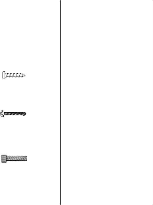
• There are two types of screws used in this kit:
Sheet Metal Screws are designated by a number and a length. For example #6 x 3/4" [19mm].
This is a number six screw that is 3/4" [19mm] long.
Machine Screws are designated by a number, threads per inch, and a length. For example 4-40 x 3/4" [19mm].
This is a number four screw that is 3/4" [19mm] long with forty threads per inch.
Socket Head Cap Screws (SHCS) are designated by a number, threads per inch, and a length. For example 4-40 x 3/4" [19mm].
This is a 4-40 SHCS that is 3/4" [19mm] long with forty threads per inch.
• When you see the term test fit in the instructions, it means that you should first position the part on the assembly without using any glue, then slightly modify or custom fit the part as necessary for the best fit.
•Whenever the term glue is written you should rely upon your experience to decide what type of glue to use. When a specific type of adhesive works best for that step, the instructions will make a recommendation.
•Whenever just epoxy is specified you may use either 30-minute (or 45-minute) epoxy or 6-minute
epoxy. When 30-minute epoxy is specified it is highly recommended that you use only 30-minute (or 45-minute) epoxy, because you will need the working time and/or the additional strength.
• Photos and sketches are placed before the step they refer to. Frequently you can study photos in following steps to get another view of the same parts.
ORDERING REPLACEMENT PARTS
To order replacement parts for the Top Flite Cessna 182 ARF, use the order numbers in the Replacement Parts List that follows. Replacement parts are available only as listed. Not all parts are available separately (an aileron cannot be purchased separately, but is only available with the wing kit). Replacement parts are not available from Product Support but can be purchased from hobby shops or mail order/Internet order firms. Hardware items (screws, nuts, bolts) are also available from these outlets. If you need assistance locating a dealer to purchase parts, visit www.top-flite.com and click on “Where to Buy.” If this kit is missing parts, contact
Product Support.
Replacement Parts List
Order Number Description |
How to purchase |
|
Missing Pieces.................. |
Contact Product Support |
|
Instruction Manual............. |
Contact Product Support |
|
Full-Size Plans..................................... |
|
Not Available |
Contact your hobby supplier to purchase these items:
TOPA1755 Fuselage Set
TOPA1756 Wing Set
TOPA1757 Tail Set (Elevators and Stabilizers)
TOPA1758 Cowl
TOPA1759 Cockpit Kit
TOPA1760 Decal
TOPA1761 Window Set
TOPA1762 Aluminum Spinner
TOPA1763 Wing Struts
TOPA1764 Wing Tips
TOPA1765 Dummy Antennas
TOPA1766 Wheel Pants
TOPA1767 Landing Gear
TOPA1768 Lighting Kit
KIT INSPECTION
Before starting to build, compare the parts in this kit with the Replacement Parts List and note any missing parts. Also inspect all parts to make sure they are of acceptable quality. If any parts are missing, broken or defective, or if you have any questions about building or flying this airplane, please contact Top Flite at the address or telephone number below. If requesting replacement parts, please provide the full kit name (Cessna 182 ARF) and the part numbers as listed in the Replacement Parts List.
Top Flite Product Support:
3002 N. Apollo Drive, Suite 1
Champaign, IL 61822
Telephone: (217) 398-8970
Fax: (217) 398-7721
E-mail: productsupport@top-flite.com.
5

|
|
|
19 |
|
|
|
|
|
|
|
|
|
20 |
|
|
|
|
|
18 |
19 |
|
|
|
1 |
|
|
4 |
|
|
|
|
|
|
|
|
|
|
|
|
|
|
2 |
3 |
|
|
|
|
|
|
|
|
|
|
|
|
|
|
|
|
|
|
|
21 |
|
|
|
5 |
|
|
|
|
|
|
|
6 |
|
|
22 |
|
|
|
|
|
|
|
23 |
|
|
|
|
|
|
|
|
|
|
7 |
|
10 |
|
|
|
|
|
|
|
|
|
|
|
|
|
|
|
|
|
|
|
28 |
|
|
|
|
|
24 |
|
29 |
|
|
|
|
|
|
|
|
|
|
|
|
25 |
|
27 |
29 |
|
|
|
|
|
|
|
|
|
|
8 |
|
|
|
26 |
30 |
|
|
|
11 |
|
|
|
|
|
|
|
|
|
|
2 |
|
|
|
9 |
|
|
|
|
|
|
|
31 |
32 |
|
|
|
|
|
16 |
|
27 |
|
|
|
|
|
14 |
|
|
12 |
|
|
33 |
|
|
|
|
|
|
|
34 |
|
13 |
|
|
15
17
2
35
6
KIT CONTENTS
1.Right Wing Tip
2.Wheels (3)
3.Right Wheel Pant
4.Hook & Loop Material
5.Right Landing Gear
6.Right Wing Panel (with Flap & Aileron)
7.Right Wing Strut
8.Adjustable Engine Mount
9.Fuel Tank
10.Fuselage
11.Cowl
12.Spinner
13.Nose Gear Wire
14.Windshield
15.Nose Wheel Pant
16.Left Wing Panel (with Flap & Aileron)
17.Left Wing Strut
18.Horizontal Stabilizer
19.Right & Left Elevator Halves
20.Rudder
21.Tail Cone
22.Side Windows
23.CA Hinge Material
24.Rear Window
25.Left Landing Gear
26.Left Wheel Pant
27.Wing Joiners (6)
28.3-Way Light Connector
29.Lights (2)
30.Lighting Switch
31.Wing Center Section
32.Servo Mounting Blocks (8)
33.Elevator & Rudder Servo Trays
34.Receiver Tray Parts
35.Left Wing Tip
preparations
o 1. If you have not done so already, remove the major parts of the kit from the box and inspect for damage. If any parts are damaged or missing, contact Product Support at the address or telephone number listed in the “Kit Inspection” section on page 5.
o 2. Remove the tape and carefully separate all the control surfaces. Use a covering iron with a covering sock on medium/high heat to tighten the covering if necessary. Apply pressure over sheeted areas to thoroughly bond the covering to the wood.
ASSEMBLE THE WING
HINGE THE AILERONS AND FLAPS
Do the right wing first so your work matches the photos the first time through.You can do one wing at a time, or work on them together. Also, we suggest reading the entire flap installation procedure before beginning this section so you will have an understanding of how they are hinged before gluing.
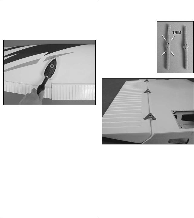
o o 1. Trim the triangular tabs from both sides of three hinge points using a sharp hobby knife (protect your fingers by holding the hinges with pliers while trimming the tabs). Test fit (without glue) the hinge points into the pre-drilled pockets in the flap and wing so that the hinging direction of each hinge point is parallel with the leading edge of the flap. Press the hinge points into the pockets until the pin in each of the hinge points is positioned over the flap hinge line when the flap is in the up position as shown. Work the flap up and down, ensuring that the flap moves freely. When the flap is in the up position, it should sit flush against the trailing edge of the wing.
7
Before performing steps 2 and 3, have denatured alcohol and some paper towel pieces ready for epoxy cleanup.
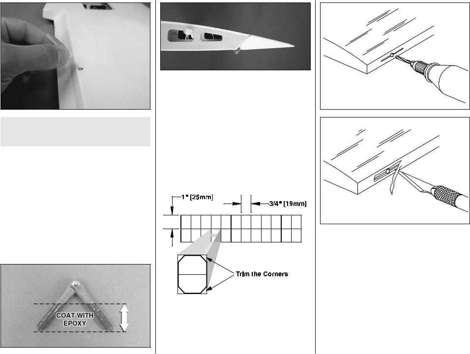
o o 2. Make note how deep the hinge points fit into the hinge pockets. Epoxy will be applied to the hinges only on the portion that fits into the pockets. Remove the flap from the wing panel and pull the hinge points from the pockets. Coat the center of each hinge point with petroleum jelly or oil. This will prevent epoxy from sticking to the pivoting portion of the hinges and will keep the hinges moving smoothly. Mix up a batch of 30-minute epoxy. Use a toothpick or something similar to coat the insides of the hinge point pockets in the flap and the wing panel. Wipe away any excess epoxy from around the pockets using a paper towel dampened with alcohol.
o o 3. Coat the portion of each hinge point that fits into the hinge pockets with epoxy. Insert the hinges into the pockets in the flap and wing as was done in step 1. Use a paper towel dampened with denatured alcohol to clean up any epoxy. Work the flap up and down to ensure it moves freely. Look at the flap from the root rib and confirm that when the flap is all the way in the up position, the top of the flap follows the airfoil contour of the top of the wing. Also, confirm that the flap is flush with the TE of the wing. Make any small adjustments to the hinges as necessary. When satisfied, set the wing aside and let the epoxy cure undisturbed.
o o 4. Cut the included 2” x 9” [51mm x 229mm] piece of CA hinge material into 3/4” x 1” [19mm x 25mm] individual hinges. Use a hobby knife or scissors to trim the corners from each hinge to make them easier to insert into the hinge slots.
8
Drill a 3/32" [2.4mm] hole |
1/2" [13mm] deep, in the center |
of the hinge slot. |
Cut the covering |
away from the slot. |
o o 5. Drill a 3/32” [2.4mm] hole 1/2” [13mm] deep in the center of each hinge slot in the wing panel and aileron. Use a sharp hobby knife to carefully cut away the covering just around each hinge slot in the wing.
Temporary pin
to keep the hinge
centered.
o o 6. Fit a CA hinge into each hinge slot in the wing panel. If the hinges are difficult to install, use a hobby knife to slightly enlarge the slots. Push a pin (T-pins work well for this) through the middle of each hinge to keep them centered.
o o 7. Fit the aileron to the hinges and align the root edge of the aileron with the root of the trailing edge for the aileron on the wing panel as shown. Remove the pins from the hinges and position the aileron against the trailing edge of the wing panel. The hinge gap between the aileron and wing should only be wide enough to allow a small line of light through. When satisfied, apply 6 drops of thin CA glue to the center of each hinge on both sides. When the CA has dried, gently pull on the aileron to confirm that it is securely glued in place.
o 8. Repeat steps 1-7 for the left wing panel.
INSTALL the AILERON SERVO & LINKAGE
Before completing this section, confirm that the servos that you will be using will properly fit between the servo mounting block locations on the aileron and flap servo hatch covers. Make adjustments as necessary for your brand servos. The block locations shown in this section will fit a standard size Futaba brand servo.
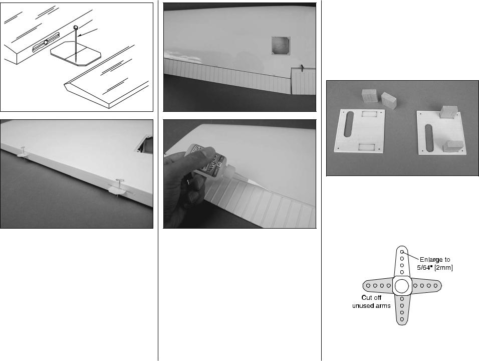
o o 1. Use epoxy to glue the 3/4" x 3/4" x 5/16" [19 x 19 x 8mm] hardwood servo mounting blocks to the inside of the aileron hatch cover. Be sure that the blocks are aligned over the rectangles with the grain direction perpendicular to the covers as shown. Allow the epoxy to cure undisturbed.
o o 2. Cut three arms from a four-armed servo arm included with the aileron servo. Enlarge the outer hole of the remaining arm with a 5/64" [2mm] drill bit.
9

o o 3. Attach a 24" [610mm] servo extension to each aileron servo and secure the connector using tape or heat shrink tubing. Center the servos with your radio system and install the servo arm to the servo perpendicular to the servo case as shown. Be sure to reinstall the servo arm screw into the servo.
o o 4. Position the servo against the underside of the aileron servo hatch cover between the mounting blocks. Shim the aileron servo away from the hatch cover approximately 3/64" [1.2mm] to isolate it from vibration (a business card folded in thirds works well for this). Drill 1/16" [1.6mm] holes through the mounting tabs on the servo case into the blocks. Thread a servo mounting screw (included with the servo) into each hole and back it out. Apply a drop of thin CA to each hole to harden the wood. When the CA has dried, install the servo onto the hatch cover using the hardware supplied with the servo.
o o 5. Use the strings taped inside the aileron servo hatches to pull the servo leads through the wing ribs.
o o 6. Thread a #2 x 3/8" [9.5mm] self-tapping screw into each hatch mounting hole in the wing and back it out. Apply a drop of thin CA to each hole to harden the wood. Install the aileron hatch cover to the wing as shown using four #2 x 3/8" [9.5mm] selftapping screws.
o o 7. Thread a nylon clevis 15 complete turns onto a 6" [152mm] pushrod. Slide a silicone clevis retainer onto the clevis and connect the clevis to the outer hole of a nylon control horn.
o o 8. Position the control horn onto the aileron between the two corrugations that are inline with the aileron servo arm. Align the holes in the control
10
horn directly over the aileron hinge line and mark the location of the control horn mounting holes.
o o 9. Drill 1/16" [1.6mm] holes at the marks you made through the plywood plate inside the aileron. Do not drill all the way through the aileron! Thread a #2 x 3/8" [9.5mm] self-tapping screw through each hole and back it out. Apply a couple drops of thin CA glue to each hole to harden the wood. When the glue has dried, install the control horn onto the aileron using two #2 x 3/8" [9.5mm] self-tapping screws.
Servo Horn
2-56 (.074") 
 Pushrod Wire FasLink 1/16"
[1.6mm]
o o 10. Use tape or a small clamp to hold the aileron in the neutral position. Make a mark on the
pushrod where it crosses the outer hole in the servo arm. Make a 90° bend at the mark on the pushrod and cut off the excess pushrod 3/16" [4.8mm] beyond the bend. Attach the pushrod to the servo arm using a nylon FasLink. Thread the clevis up or down on the pushrod as necessary to center the aileron with the servo arm centered. Slide the silicone clevis retainer to the end of the clevis to secure it.
o 11. Repeat steps 1 to 10 for the left wing panel.
INSTALL the FLAP SERVO & LINKAGE
oo1. As you did with the aileron, glue the mounting blocks to the underside of the flap servo hatch cover. When the epoxy has cured, attach the flap servo to the hatch cover using the hardware included with the servo. Center the servo with your radio system and install a servo arm at a 30° angle as shown. The flap servo does not require a servo extension.
o o 2. Prepare the flap linkage by threading a nylon clevis onto a 4" [102mm] pushrod 15 complete
turns. Install a silicone clevis retainer onto the clevis. Measure 3-1/4" [83mm] from the clevis pin and make a bend in the pushrod. Cut off the excess pushrod 3/16" [4.8mm] beyond the bend.
o o 3. Slide the pushrod through the access hole in the wing and connect the bent end of the pushrod to the outer hole in the flap control horn using a nylon FasLink. Connect the clevis to the outer hole in the flap servo arm. Put the flap servo hatch cover in place onto the wing. While holding the hatch cover down, use your radio system to test the operation of the flap. Make any adjustments necessary to the position of the clevis on the pushrod or the servo arm.
11
 Loading...