


Before beginning construction of your Bonanza you should make these following corrections:
Fuselage Plan The correct site of the rudder/fintip block (BON9S08) is: 5/8" x 7/8'x 6-1/4'
Page 57, step 7 |
- Change F2to F1A. |
|
|
Page 57,step 9 |
- |
Change F2 to F1A. |
|
Page58,step 17 |
- Change "..along the cut lines .." to "..about l/l6"inside the cut lines." |
||
Page 58,step 2 |
- |
Change "..Phillips head . |
to .Socket Head Cap Screw. ." |
Page 60,step 4 |
- |
Change 1" x 1-3/4"X2"-3/8'x 1-3/8' x 1-1/2' |
|
Page 62,step 15 |
- Change Fuselage to "cowl" |
Page 64,step (wing)l - Add " as" after the word "such" |
|
Page 68,step 10 |
-Add sure" after the word "make" |
Page 69,control throw chart -Trim mixing section change references to "Down" to "Up"

WARRANTY. ....TOP Flite Models guarantees this kit to be free of defects in both materials and workmanship at the date of purchase. This warranty does not cover any component parts damaged by use or modification. In no case shall Top Flite's liability exceed the original cost of the purchased kit. Further, Top Flite reserves the right to change or modify this warranty without notice.
In that Top Flite has no control over the final assembly or material used for final assembly, no liability shall be assumed nor accepted for any damage resulting from the use by the user of the final user-assembled product. By the act of using the user-assembled product the user accepts all resulting liability.
If the buyer is not prepared to accept the liability associated with the use of this product, the buyer is advised to immediately return this kit in new and unused condition to the place of purchase.
I J
Top Flite Models
P.O. Box 788
Urbana, IL 61803
Technical Assistance - Call (217) 398-8970
READ THROUGH THIS INSTRUCTION BOOK FIRST. IT CONTAINS IMPORTANT INSTRUCTIONSAND WARNINGS CONCERNINGTHE ASSEMBLY AND USE OF THIS MODEL.
Entire Contents - Copyright 1997 3005140 |
BON9P03 |

INTRODUCTION ................................................ |
3 |
PRECAUTIONS.................................................. |
4 |
DECISIONS YOU MUST MAKE......................... |
4 |
Tail configuration ............................................ |
4 |
Engine selection ............................................. |
4 |
Exhaust system .............................................. |
4 |
Retractable landing gear ................................ |
4 |
Flaps............................................................... |
4 |
TOP FLITE SCALE ACCESSORIES ................. |
5 |
Operational lighting......................................... |
5 |
Scale cockpit interior ...................................... |
5 |
NOTES FOR COMPETITION MINDED |
|
MODELERS........................................................ |
5 |
DOCUMENTATION............................................ |
5 |
OTHER ITEMS REQUIRED ............................... |
5 |
Accessories .................................................... |
5 |
Building supplies............................................. |
6 |
IMPORTANT BUILDING NOTES....................... |
6 |
COMMON ABBREVIATIONS ............................ |
7 |
TYPES OF WOOD.............................................. |
7 |
METRIC CONVERSIONS................................... |
7 |
NOTES FROM THE DESIGNER........................ |
7 |
DIE-CUT PATTERNS .................................. |
8 & 9 |
GET READY TO BUILD................................... |
10 |
BUILD THE TAIL SURFACES......................... |
10 |
Make the skins for the tail surfaces .............. |
10 |
Build the stab and elevators (straight-tail) ....11 |
|
Build the fin and rudder (straight-tail) ........... |
15 |
Build the stab and ruddervators (V-tail) ........ |
17 |
Make the stab tips ........................................ |
20 |
BUILD THE WING ............................................ |
21 |
Make the wing skins ..................................... |
21 |
Preparations................................................. |
21 |
Build the outer wing panels .......................... |
22 |
Sheet the top of the wing panels .................. |
23 |
TABLE OF CONTENTS
Finish the outer wing panels |
......................... |
24 |
Build the center section ................................ |
|
27 |
Sheet the top of the center section............... |
28 |
|
Prepare the bottom of the wing for sheeting.28 |
||
Sheet the bottom of the wing ............panels |
30 |
|
Cut out the wheel wells................................. |
|
31 |
Build the wing tips......................................... |
|
31 |
Build the flaps ............................................... |
|
32 |
Build the ailerons .......................................... |
|
34 |
Mount the flap and aileron servos ................ |
34 |
|
Join the wing panels ..................................... |
|
35 |
BUILD THE FUSELAGE.................................. |
: |
36 |
Preparation........................... ....................... |
36 |
|
Build the bottom of the fuselage ................... |
37 |
|
Mount the servos .......................................... |
|
38 |
Finish framing the fuse ................................. |
|
38 |
Sheet the fuselage sides .............................. |
|
39 |
Glue the tail cone together ........................... |
|
40 |
MOUNT THE V-TAIL STAB ............................. |
|
40 |
Build the turtle deck (V-tail) .......................... |
|
42 |
Hook up the ruddervators............................. |
|
43 |
Fit the tail cone ............................................. |
|
44 |
MOUNTTHE STRAIGHT-TAIL STAB AND FIN |
.....45 |
|
Center the stab ............................................. |
|
45 |
Align the stab horizontally............................. |
|
46 |
Mount the fin ................................................. |
|
47 |
Build the turtle deck (straight .................-tail) |
47 |
|
Hook up the rudder and elevator .................. |
49 |
|
Build the dorsal fin ........................................ |
|
49 |
Fit the tail cone ............................................. |
|
50 |
MOUNT THE ENGINE...................................... |
|
50 |
MOUNT THE NOSE LANDING .............GEAR |
52 |
|
Fixed gear..................................................... |
|
52 |
Retractable gear ........................................... |
|
53 |
FINISH CONSTRUCTION................................ |
|
55 |
Hook up the throttle ...................................... |
|
55 |
Sheet the forward deck and ..............bottom |
56 |
|
Fit the cabin top ............................................ |
|
57 |
Mount the cabin top ...................................... |
|
58 |
Fit the windows ............................................. |
|
59 |
Mount the wing to the fuse ........................... |
|
55 |
Sheet the bottom of the wing center section 60 |
||
Make the belly pan ....................................... |
|
60 |
Build and fit the cowl to the fuselage ............ |
61 |
|
FINISHING........................................................ |
|
63 |
Fuel proofing................................................. |
|
63 |
Cabin details................................................. |
|
63 |
Scale details ................................................. |
|
63 |
Final sanding ................................................ |
|
63 |
Cover Top Flite MonoKote film ..................... |
|
64 |
Painting......................................................... |
|
64 |
Join the control surfaces............................... |
|
65 |
Glue in the windows ..................................... |
|
65 |
Make door and hatch outlines ...................... |
|
66 |
Apply the decals ........................................... |
|
66 |
GET YOUR MODEL READY TO FLY.............. |
66 |
|
Balance your model...................................... |
|
66 |
Balance the airplane laterally ....................... |
|
67 |
Install your receiver and battery pack........... |
67 |
|
Control surface throws ......................... |
|
68 & 69 |
PREFLIGHT...................................................... |
|
69 |
Charge your batteries ................................... |
|
69 |
Balance your propellers................................ |
|
69 |
Find a safe place to fly.................................. |
|
69 |
Ground check your model ............................ |
|
69 |
Range check your radio................................ |
|
69 |
Engine safety precautions ............................ |
|
69 |
FLYING............................................................. |
|
70 |
Fuel mixture adjustment ............................... |
|
70 |
Takeoff .......................................................... |
|
70 |
Flying............................................................ |
|
70 |
Landing......................................................... |
|
71 |
Flaps............................................................. |
|
71 |
TWO-VIEW DRAWING..................... |
Back Cover |
|
-2-
PROTECT YOUR MODEL,
YOURSELF& OTHERS -FOLLOW
THIS IMPORTANT SAFETY
PRECAUTION
Your Beechcraft Bonanza is not a toy, but a sophisticated working model that functions very much like an actual airplane.
Because of its realistic performance, if you do not assemble and operate your Bonanza correctly, you could possibly injure yourself or spectators and damage property.
To make your R/C modeling experience totally enjoyable, get assistance with assembly and your first flights from an experienced, knowledgeable modeler. You’ll learn faster and avoid risking your model before you’re truly ready to solo. Your local hobby shop has information about flying clubs in your area whose membership includes qualified instructors.
You can also contact the Academy of Model Aeronautics (AMA), which has more than 2,300 chartered clubs across the United States. We recommend you join the AMA which will insure you at AMA club sites and events. AMA Membership is required at chartered club fields where qualified flight instructors are available.
Contact the AMA at the address or toll-free phone number below:
S I N C E 1936
Academy of Model Aeronautics
5151 East Memorial Drive
Muncie, IN 47302
(800) 435-9262
Fax (765) 741-0057
Your Top Flite Gold Edition Beechcraft Bonanza is intended for scale and general sport flying including mild aerobatics such as loops, stall turns, rolls, etc. Its structure is designed to withstand such stresses. If you intend to use your Bonanza for more abusive types of flying such as racing, aggressive aerobatics, or flying from rough fields, it is your responsibility to reinforce areas of the model that will be subjected to the resulting unusually high stresses.
INTRODUCTlON
Thank you for purchasing the Top Flite Gold
Edition Beechcraft Bonanza.
From this kit you can build either the V35B V-tail (1970, 1971) or the F33A straight tail (1970, 1971). If you like the looks of the V-tail best, don’t be intimidated. Actually, the V-tail is a little easier to build than the straight tail because it has fewer parts! See page 7 for more comments on the differences between the V-tail and the straight tail.
Since this is a scale model with lots of detail, you’ll find it takes a little longer to complete than the sport models you’ve built before. But since this is a Top Flite Gold Edition kit, it isn’t more difficult to build than those sport models. The Top Flite Bonanza uses the same materials and standard construction techniques you’ve already become accustomed to. You won’t have to learn anything new to end up with a first class scale model! Not only that, nearly all of the trim schemes you’ll find on full size Bonanzas are quite simple and should be easy to duplicate with Top Flite MonoKote film! The Top Flite Beechcraft Bonanza is an excellent Sportsman or Expert Scale subject. Its large size and accurate scale outline afford you the opportunity to go all out with as many extra details as you like. And with the abundance of Bonanzas at airports around the country, finding a full scale plane to model shouldn’t be a problem. The option of building either a V-tail or conventional tail opens up the possibilities even more!
- 3 -
Anyone who has mastered a low wing sport model should be able to fly the Bonanza without difficulty. It handles very much like a full size Bonanza-smoothandpredictable.
Because of its 81” wingspan, the Top Flite Beechcraft Bonanza is eligible for IMAA* events. In order to be IMAA legal some of the control components and hardware may need to be replaced to conform to Giant Scale rules even though this model does not require heavy duty hookups.
Several scale accessories specially designed for the Top Flite Bonanza are available separately including a full cabin interior, in-cowl exhaust system, and a complete lighting kit. See the Scale Accessories section on page 5 for more information.
*IMAA (International Miniature Aircraft Association) is an organization that promotes non-competitive flying of giant scale models.
IMAA
International Miniature Aircraft Association
205 S. Hilldale Road
Salina, KS 67401
Please inspect all parts carefully before starting to build! If any parts are missing, broken or defective, or if you have any questions about building or flying this model, please call us at (217) 398-8970 and we’ll be glad to help. If you are calling for replacement parts, please look up the part numbers and the kit identification number (stamped on the end of the carton) and have them ready when calling.

PRECAUTIONS
 You must build the plane according to the plans and instructions. Do not alter or modify the model, as doing so may result in an unsafe or unflyable model. In a few cases the plans and instructions may differ slightly from the photos. In those instances you should assume the plans and written instructions are correct.
2.You must take time to build straight, true and strong.
3.You must use a proper RIC radio that is in first class condition, the correct sized engine and correct components (fuel tank, wheels, etc.) throughout your building process.
4.You must properly install all R/C and other components so that the model operates properly on the ground and in the air.
5.You must test the operation of the model before every flight to insure that all equipment is operating, and you must make certain that the model has remained structurally sound. Be sure to check external nylon clevises often and replace them if they show signs of wear.
6.If you are not already an experienced R/C pilot you must fly the model only with the help of a competent, experienced R/C pilot.
NOTE: We, as the kit manufacturer, can provide you with a top quality kit and great instructions, but ultimately the quality and flyability of your finished model depends on how you build it; therefore, we cannot in any way guarantee the performance of your completed model, and no representations are expressed or implied as to the performance or safety of your completed model.
Remember: Take your time and follow directions to end up with a well-built model that is straight and true.
DECISIONS YOU MUST MAKE
TAIL CONFIGURATION
You may build your Bonanza as a straight tail or a V-tail. Complete instructions are provided for both. The main differences in construction are building the tail surfaces themselves, the way they mount to the fuse, and the turtle deck
sheeting. If you wish to utilize the elevators as ruddewators (elevators and rudder) on the V-tail, you will need a computer radio with V-tail mixing or a servo mixer such as the Ace MixMaster (ACEM2510). However, the Bonanza will fly just fine with elevators only and no rudder input. Do not be intimidated by the V-Tail configuration. It flies beautifully and is as easy to handle as the straight tail.
ENGINE SELECTION
Recommended engine size:
.60 to .91 cu. in. 2-stroke -or- .90 to ,120 cu. in. 4-stroke
The Bonanza will fly well with any of the recommended engines. The 4-stroke engines and most .75 2-stroke engines will turn a larger prop at lower RPM’s. This is often desirable for scale realism. Many .60 2-stroke engines produce about as much horsepower as the popular .75 or .90 2-stroke engines and will fly the Bonanza well. If you use a .60 2-stroke, a ball bearing, Schnuerle-ported engine is highly recommended. Our prototype Bonanza weighed 13 pounds with all of the options, including flaps, scale cockpit interior and operational lighting, and was flown with a SuperTigre G-75. It turned a Top Flite Power Point 12x8 prop at 9,600 RPM.
This engine provided excellent performance and more than enough power, even in gusty winds. Although larger engines can be used to power this model, the extra horsepower is not needed.
The included adjustable engine mount will hold a range of engines from .60 2-stroke through 1.20 4-stroke.
EXHAUST SYSTEM
A Top Flite header and muffler are available that will fit inside your cowl. They are designed for 2-stroke engines mounted horizontally, as used on the model and shown in the instructions.
For part numbers see the accessory list on page 6.
RETRACTABLE LANDING GEAR
You may build the Bonanza either with fixed or retractable landing gear. Of course, fixed gear will be much easier to install than retracts; but we provide detailed instructions on retract installation so you should have no trouble. We chose the Robart #BZA80 retracts because they are specially designed for this model. This landing gear is a special adaptation of the Robart #640 mains and the #631 nose gear. Other systems may work as well but it is up to you to make modifications to fit them into the model.
FLAPS
This model was designed to incorporate scale flaps; however,flaps are optional are not necessary for an excellent flying experience. Without flaps, the takeoff roll is longer and the landing speed is faster.
The flaps are not difficult to build, but they do require good craftsmanship to fit well. Flaps add nicely to the model’s flight characteristics and scale appearance while causing no bad effects. Only slight trim correction is needed when they are used with the recommended throws. They are a highly recommended fun option for those who wish to install them. More information on the use of the flaps may be found in the “Flying” section.
For part numbers see the accessory list on page 5.
- 4 -
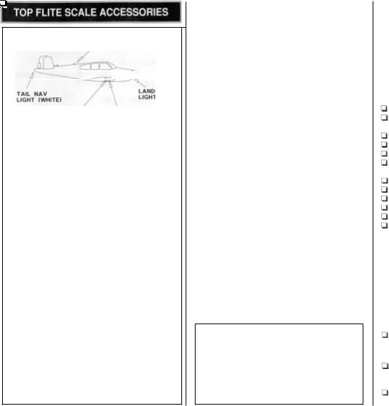
Operational lighting
ROTATING BEACON
ING
NAVIGATION LIGHTS |
\ |
STROBE LIGHT |
|
(GREEN-RIGHT, RED-LEFT) |
|
An operational lighting system (TOPQ7912) has been developed specially for the Top Flite Bonanza and was installed in our prototypes. Guidelines are provided in this manual for building the wiring into the wing and building brackets to hold the wing tip and tail navigation lights. You can install the lights in the fuse at any time. The instructions included with the lighting kit provide information on how to hook everything up. The lighting kit includes one rotating beacon for the top of the fuselage, one landing light for the front of the cowl, and three navigation or position lights for the wing tips and tail cone (green in the right wing tip, red in the left wing tip, and white in the tail cone). If you would like to add the strobe lights in the wing tips, order RAM #RAM01 (RAMQ2301) and purchase additional clear lenses directly from RAM.
Scale cockpit interior
Your model won't be complete without the Top Flite Beechcraft Bonanza Scale Cabin Interior (TOPQ8402). It includes the floor, side panels, full instrument panel and six seats! You can install the Cabin Interior at any time because the cabin top is removable but it's easiest to build the cockpit into the model while it's under construction. The servos and pushrods are located so the Cabin Interior can be installed without any modification.
NOTES FOR COMPETITION MINDED MODELERS
We designed our model from Beechcraft's own 1969 3-view drawings and from measurements taken from a V35B at a local airport. The model scale is 1 5 .
If you plan to enter your Bonanza in scale competition (it's lots of fun, and the runways are almost always paved!), this kit qualifies for Fun Scale and the Sportsman and Expert classes in Sport Scale. Fun Scale and Sport Scale have the same flight requirements where you must perform ten maneuvers of which five are mandatory. If you have never competed in a scale contest, you could start out in Fun Scale. In Fun Scale, the only documentation you need for static judging is any proof that a full size aircraft of this type, in the painffmarkings scheme on your model, did exist. A single photo, kit box cover, even a painting is sufficient proof! If you're interested, contact the AMA for a rule book which will tell you everything you need to know. Look in the back of the AMA magazine Model Aviation for a schedule of events.
The trim scheme of the Bonanza on your kit box was inspired by several trim schemes and is not taken from one particular plane. If you are not too concerned with an exact scale trim scheme you can duplicate the one on the kit box, make a variation of the one on the box, or design your own trim scheme. If you are going to compete in scale competition use the photos in your documentation package as a guide for your trim scheme.
DOCUMENTATION
three view drawings and photo packs of full size Beechcraft Bonanzas are available from:
Scale Model Research,
3114 Yukon Ave, Costa Mesa, CA 92626
(714) 979-8058
OTHER ITEMS REQUIRED
Accessories
These are additional items you will need to complete your Bonanza that are not included with your kit. Order numbers are in parentheses (GPMQ4130). Our exclusive brand is listed where possible: TOP is the Top Flite brand, GPM is the Great Planes brand, and HCA is the Hobbico brand.
4- to 6-channel radio with 6 to 9 servos
(2) 24" extension for ailerons
(2) 12" extension for elevator and rudder servo
(1) " Y Harness for ailerons
3-1/2" Main Wheels (ROBQI516)
2-3" Nose Wheel (ROBQI513)
(6) 3/16 Wheel Collars (GPMQ4309)
14 oz. Fuel Tank (GPMQ4106)
2-3/4" White Spinner (GPMQ4525)
36" Medium Silicone Fuel Tubing (GPMQ4131) 1 / 2 R/C Foam Rubber Padding (HCAQ1050) 1/5 Scale Pilot Figures (WBRQ2485)
Fuel Filler Valve (GPMQ4160)
Exhaust Deflector (HCAP2175)
3-4 rolls Top Flite Super MonoKote covering, see Finishing on page 64
Paint, see Finishing on page 64 Propellers, see the engine instructions
Items for V-tail with elevator only:
(1) " Y Harness for elevator servos (if building V-tail with elevator only)
For Flaps, the following additional items will be required:
(1) " Y Harness
OR
(2) 9" Servo Extensions
(1) Dual Servo Extension
Robart #309 Super Hinge Points (ROBQ2509) Two standard servos
- 5 -
For an In Cowl Muffler setup, the following items will be required:
O.S.61SF & FX Top Flite Header (TOPQ7920) SuperTigre .61-.90KTop Flite Header (TOPQ7925) SuperTigre .75-.9OGTop Flite Header (TOPQ7926)
.61-.75 Bonanza In CowlMuffler (TOPQ7917)
BUILDING SUPPLIES
Here's a checklist of supplies you should have on hand while you're building. We recommend Great
CA and Epoxy.
Glue/Filler
4 oz. Thin CA (GPMR6003)
4 oz. Medium CA+ (GPMR6009)
2 oz. Thick CA- (GPMR6015)
CA Accelerator (GPMR6035)
CA Debonder (GMPR6039)
CA Applicator Tips (HCAR3780)
30-minute epoxy (GPMR6047)
6-minute epoxy (GPMR6045)
Pro Wood Glue (GPMR6161)
J & Z Products Z RC/56 canopy glue (JOZR5007)
Microballoons (TOPR1090)
Milled Fiberglass (GPMR6165)
Lightweight Hobby Filler (BalsaColor, HCAR3401)
Auto body filler (Bondo@or similar) 3M #75 Spray Adhesive (MMMR1900) Denatured or lsopropyl Alcohol
Tools
#11 Blades (HCAR0311, 100 qty.)
Single Edge Razor Blades (HCARO312, 100 qty.)
Razor Plane (MASRl510) X-Acto@Building Square (XACR7726) X-Act0 Building Triangle (XACR7725) T-Pins (HCAR5100 - small, HCAR5150 - medium, HCAR5200 - large)
Drill Bits: |
1/16" |
17/64" |
|
3/32" |
9/32" |
|
1/8 |
5/16" |
|
5/32" |
9/64" or #29 |
|
Q 3/16" |
u11/64"or#10 |
|
1 / 4 |
13/64" or #7 |
Tools (Cont.)
 1/4-20 Tap and drill set (GPMR8105) 8-32 Tap and drill set (GPMR8103)
 Kyosho" LexarP Curved Scissors (KYORl010)
 Long handle 9/64 ball driver (GPMR8004)
 Long handle 3/32" ball driver (GPMR8002)
 Silver Solder (GPMR8070w/flux)
 Masking Tape
 Wax Paper
 Easy-Touch'" Bar Sanders*
 Heat Gun (TOPR2000)
 Trim Seal Tool (TOPR2200)
 Hot Sock (TOPR2175)
  Sealing Iron (TOPR2100)
EASY-TOUCHTM
HAND SANDER
*A flat, durable, easy to handle sanding tool is a necessity for building a well finished model. Great Planes makes a complete range of Easy-Touch Bar Sanders (patent pending) and replaceable
Easy-Touch adhesive-backed sandpaper. While building the Bonanza we used two 5-1/2" Bar Sanders and two 11" Bar Sanders equipped with 80-grit and 150-grit adhesive-backed sandpaper.
Here's the complete list of Easy-Touch Bar Sanders and adhesive backed sandpaper:
5-1/2 Bar Sander |
(GPMR6169) |
11" Bar Sander |
(GPMR6170) |
22" Bar Sander |
(GPMR6172) |
12' roll of Adhesive-backed sandpaper
80-grit |
(GPMR6180) |
150-grit |
(GPMR6183) |
220-grit |
(GPMR6185) |
Assortment pack of 5-1/2 strips (GPMR6189)
We also use 3M 320-grit or 400-grit wet-or-dry sandpaper for finish sanding.
IMPORTANT BUILDING NOTES
There are two types of screws used i\n this kit:
Sheet metal screws are designated by a number and a length.
For example #4 x 5/8":
Machine screws are designated by a number, threads per inch, and a length.
For example 4-40 x 3/4":
 When you see the term test fit in the instructions, it means that you should first position the part on the assembly without using any glue, then slightly modify or custom fit the part as necessary for the best fit.
. Whenever the term glue is used this means you should rely upon your experience to decide what type of glue to use. When a specific type of adhesive works best for that step we will tell you what type of glue to use.
 Whenever just epoxy is specified you may use either 30-minute epoxy or 6-minute epoxy. When 30-minute epoxy is specified it is highly recommended that you use only 30-minute epoxy because you will need the working time and/or the additional- strength.
Occasionally we refer to the top or bottom of the model or up or down. To avoid confusion, the top or bottom of the model is as it would be when the airplane is right side up and will be referred to as the top even if the model is upside down during that step, i.e. the top main spar is always the top main spar even if the wing is upside down when you are working on it. Similarly, move the former up means move the former toward the top of the fuselage even if the fuselage is upside down when you are working on it.
 Incidence and Thrust Angles: The incidence angles and down thrust angles shown on the fuselage side view are in reference to the stepped main fuselage stringer (the 1/4" x 3/8" x 36" stepped stringer), which is set at 0". The right thrust shown on the bottom view is in reference to the centerline of the fuselage. Remember, this is
- 6 -
the bottom view so right thrust is viewed as an offset to the left from the bottom.
 When you get to each step, read that step completely through to the end before you begin. Frequently there is important information or a note at the end of the step that you need to know before you start.
 Photos and sketches are placed ahead of the step they refer to. Frequently you can study photos in following steps to get another view of the same parts.
COMMONABBREVIATIONS USED IN
THIS BOOK AND ON THE PLANS:
Deg = Degrees
Ply = Plywood
Fuse = Fuselage
LE = Leading Edge (front)
LG = Landing Gear
Lt = Left
Rt = Right
Stab = Stabilizer
TE = Trailing Edge (rear)
" = Inches
Elev = Elevator
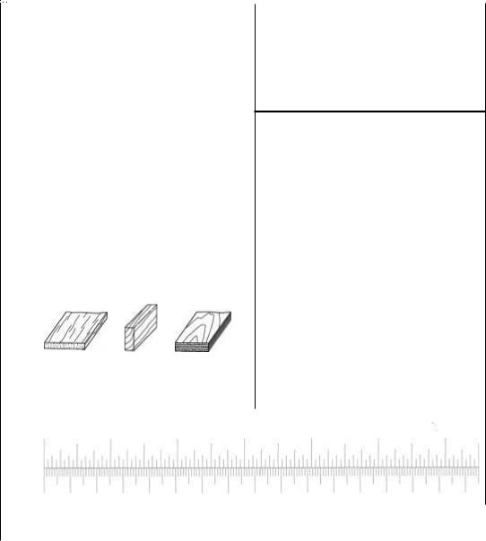
TYPES OF WOOD:
.,..._..... . . |
|
|
Balsa |
Basswood |
Plywood |
Inch Scale
0" 1" 2" 3"
INCHES X 25.4 = MM (CONVERSION FACTOR)
1/64" = .4mm |
3/4" |
= 19.0 mm |
|
1/32" = .8 mm |
1" |
= 25.4 mm |
|
1/16 = 1.6rnm |
2" |
= 50.8 mm |
|
3/32" |
= 2.4 mm |
3" |
= 76.2 mm |
118" |
= 3.2 rnrn |
6 |
= 152.4 mm |
5/32" |
= 4.0 rnrn |
12" |
= 304.8 mm |
3/16 |
= 4.8 mrn |
1 8 |
= 457.2 mm |
114" |
= 6.4 mrn |
21" |
= 533.4 mm |
3 / 8 |
= 9.5rnm |
24" |
= 609.6 mm |
1/2" |
= 12.7rnrn |
30" |
= 762.0 mm |
5/8 |
= 15.9 rnrn |
36" = 914.4 mm |
|
NOTES FROM THE DESIGNER
Scale Accuracy: The Bonanza was designed using three view drawings from Beechcraft dated 1969. In addition, measurements of all aircraft components were taken from a V35B Bonanza at a local airport.
Wing Design: The TF Bonanza was designed with an "1- Beam" type of wing spar rather than the more traditional "D- Tube" type construction. Actually, the design could be called an "I-Tube". This simplifies construction and is approximately 50% stronger than D-Tube designs. The wing was designed with an absolute minimum number of seams that must be sanded on the finished wing. The result is a very smooth wing.
Flaps: Flaps on the full scale aircraft allow steeper approaches and slower landing speeds. They do exactly the same on this model. The improvement in performance is well worth the effort.
Landing Gear: If you are installing fixed gear you will note that the strut extends out from the center of the groved rail instead of the end. This allows landing stresses to be distributed across three ply reinforced ribs, rather than being concentrated at the end of the rail. If you plan to install retractable landing gear, I highly recommend the Robart units especially designed for the Bonanza. They are very robust and include shock absorbing struts. One of our prototype models was built with Robart #606HD mains and a #607 nose unit. Though adequate, they required a lot of maintenance and occasional repair. Gear doors would look great on this model but you will have to do some modifications if you want to install then. The mounting rails
4" |
5" |
6" |
0 |
10 |
20 |
30 |
40 |
50 |
60 |
70 |
80 |
90 |
100 |
110 |
120 |
130 |
140 |
150 |
160 |
|
Metric Scale |
|
|
|
|
|
|
|
|
|
- 7 - |
|
|
|
|
|
are designed to minimize damage in the event of hard landings or contact with obstacles.
Fuselage Design: The fuselage design is fairly conventional. The cabin top is a LARGE ABS piece and it drove many of the other design elements - such as how to get it into the box! But it does simplify construction and looks great. It is designed to be removable but if you are not concerned with access to the fuel tank and cabin interior it can be permanently glued in place, allowing the seams to be filled in. We found that if you choose your trim design carefully, the seams are pretty well hidden.
The cabin area is reinforced with 1 / 8 lite ply. While it is more than strong enough, I would recommend that you reinforce the area with some basswood rails along the bottom of formers F2, F4 and F6 across the width of the fuselage. We have included ample extra 1/4" x 3/8" basswood material for this purpose.
V-Tail vs straight tail: I personally feel that a Bonanza is not a Bonanza if it isn't a V-Tail. If you are intimidated by rumors about V-Tails being hard to build or difficult to fly, you shouldn't be. The V-Tail is easier to build and just as easy to fly. I, on the other hand, was intimidated by the V-Tail! Just kidding. It was designing the model to be either a V-Tail or straight tail, using the same basic mounting structure and pushrods and showing it all on the plans that I found intimidating.
Do You Need a Computer Radio? NO!! A computer radio will simplify radio installation and allow full utilization of the ruddervators but it is in no way required. Simply connect the ruddervator servos together with a Y-cable and use them as elevators. Or use one of the many mixers available to obtain V-Tail mixing. Incidentally, this model duplicates virtually all of the flight characteristics of the full size aircraft. The rudders are somewhat ineffective and it has the characteristic Bonanza tail wiggle. The full size aircraft has differential throw when rudder is applied - the ruddervator having more up throw than down. This compensates for a nose down tendency otherwise. Try to duplicate this if you use a computer radio. We used a Futaba radio and did get the required compensation as you will note in the recommended control throws section.
Will It Really Fly On a .60 Size Engine? YES!! And very scale like as well. Our test flying was done with a new Super Tigre .75 with a TF in-cowl muffler. It was during winter and it was cold so we weren't able to dial in the engine very well. It was turning a TF 12-8 Power Point prop at 9,600 RPM and we never felt a need for more power. It flew in a very scale like manner.
Good luck and good flying. I hope you enjoy building and flying your Bonanza as much as I did designing it.


GET READY TO BUILD
 1. Unroll the plan sheets, then roll them inside out so they lie flat.
 2. Remove all the parts from the box. Use a ballpoint pen (not a felt-tip pen) to lightly write the name or size on each piece so you can identify it later. Use the die-cut patterns on pages 8 & 9 to identify and mark the die-cut parts before you remove them from their die-cut sheets. Many of the parts already have numbers stamped on them, but in some cases the number is located alongside the parts. You may remove all the die-cut parts from their die sheets now or wait until you need them. If a part is difficult to remove, don't force it out but cut around it with a # I 1 blade. After you remove the parts from their die sheets, lightly sand the edges to remove slivers or die-cutting irregularities. Save some of the larger scraps of wood.
DO NOT PUNCH OUT THE
ROUND LIGHTENING HOLE
W4, W5, W6
Note: If you are going to install retracts, don't punch out the round lightening hole in the die-cut 3/32" balsa wing ribs W4, W5 and W6. Instead, apply thin CA around the lightening hole to glue it in place.
 3. Separate the parts into groups such as stab, fin, wing and fuse.
Store smaller parts in zipper-top food storage bags.
BUILD THE TAIL SURFACES
Make the skins for the tail surfaces
 1. See the Hot Tip that follows and use six 1/16" x 3" x 30" balsa sheets to make two 1/16" x 9" x 30" stab skin planks. If you're building the straight-tail, make a third plank for the finlrudder skin from three more 1/16" x 3" x 30" balsa sheets. Hey, if you're building the V-tail it looks as if you are going to have three sheets of 1/16" balsa leftover!
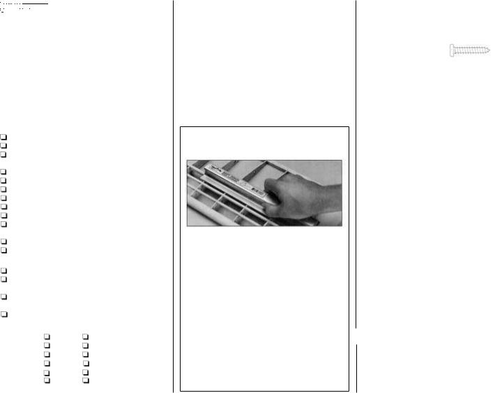
HOW TO MAKE THE SKINS
A. Use a straightedge and a sharp # I 1 blade to true the joining edges of the sheets. When you trim them, do not cut all the way through the first time but make several passes so you slice the wood instead of splitting it.
B. Tightly tape the sheets together with masking tape placed about every 4" along the seams. The sheets will not lay flat because they are tightly taped together.
C. Place wax paper on your workbench. Flip the sheets over and apply a bead of aliphatic resin (wood workers glue such as Great Planes Pro"") between the seams. Immediately proceed to the next steD.
D. Use a credit card or thin peice of plywood to squeegee the excess glue from the seam. Wipe the glue off your squeegee with a paper towel or a stick of wood. Immediately proceed to the next step.
-10-
INCORRECT: SHEETS
NOT FLAT AND EVEN
 ....
.... 


 y
y
CORRECT SHEETS ARE
FLAT AND EVEN


 . .
. . 


 ....
....
E. Press the joining edges of the sheets down with your fingers so they are flat and even. Place weights on top of the sheets to hold them flat.
F.Squeegee the glue, press the seams flat, and place weights along the other glue joint. Let the glue dry.
G.Use the same procedure to make the wing skins when you build the wing.
 2. After the glue is dry, peel off the masking tape and decide which side of the planks will be the outside. Use a bar sander or a large, flat sanding block and 150-grit sandpaper to sand the planks so they are flat, even and smooth. The idea is to do the sanding before you glue the skins to the structure.
 3. Cut the 9" x 30" sheets in half, making four (or six for the straight tail) 9" x
  planks.
LE |
Grain |
Stab
!-
Elevator (Ruddervater)
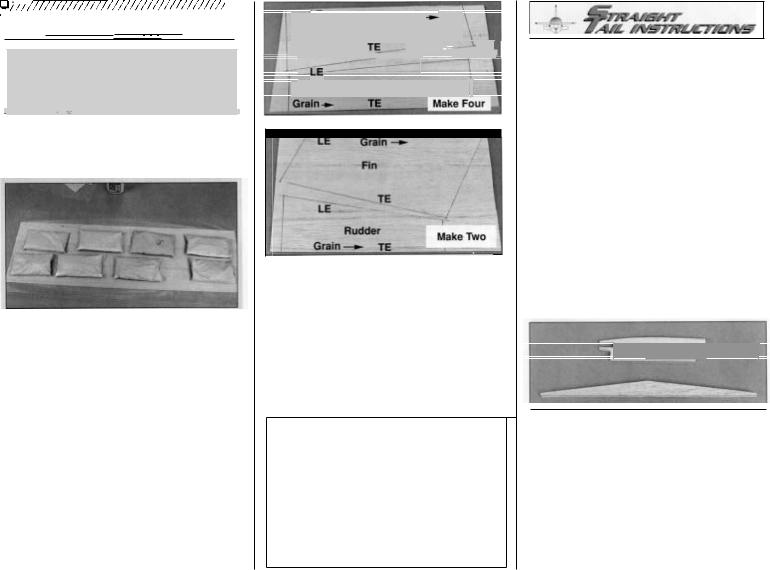
 4. Cut the stab and elevator skin templates from the plan. Use a straightedge and a ballpoint pen to mark their outline onto the 9" x
  planks (do not use a felt-tip pen). The templates are slightly oversize to allow for slight variances in construction. Note the grain direction. Cut the stab and elevator skins from the planks. If you're building the straight tail do the same for the fin and rudder skin. Note: The template shown on the plans for the elevator (ruddervator) is larger than needed. You will need to trim this to the correct size when you fit the skin into place.
B e e c h Fact: Let's get it straight. All Bonanza 35's (that's A through V including the very first Bonanza-the 35 are V-tails. Models 33 through 33C are Debonairs (more on the Debonair in a later Beech Fact). Models 33E through G are straight tail Bonanzas, as well as the very last Bonanzas produced: the 36 and A36. But it's not that simple. The designations didn't necessarily proceed from A, to B, to C, etc. There were variations of some of the models such as the V35, V35TC. V35A, V35A-TC and so on. Or, the F33, F33A and F33C. But, the number designation rule still applies. Now you can really impress your friends!
- 1 1 -
I I
If you're building the V-tail, skip to "Build the stabilizer and ruddervators" on page 17.
BUILD THE STABILIZER AND ELEVATORS
Build the right and left stab halves simultaneously. The left half of the stab plan shows the straight tail stab with dashed lines indicating the V-tail stab. The right half of the stab plan shows the V-tail stab with dotted lines indicating the straight tail stab.
 STI. Position the plan so the stab is over your flat building board (or cut the stab from the wing plan) and tape it down and cover it with wax paper.
s1s
ph
 ST2. Glue both die-cut 118" balsa straight tail LE braces together and both die-cut 3/32" balsa S1S ribs together.
ST3. Test fit the die-cut 3/32" balsa stab ribs S2S through S7S in the notches of both die-cut 1/8" balsa stab TE spars Place both assemblies over the plan and add the LE brace. See the photo at step ST4.
 Loading...