


Wingspan: 69 in [1755mm] Wing Area: 730 sq in [47.1 dm2] Weight: 8.5-9.5 lb [3855-4310g]
Wing Loading: 27-30 oz/sq ft [82-91 g/dm2] Length: 51 in [1295mm]
Radio: 6 channel w/8 servos Engine: .60 cu in [10cc] two-stroke,
.70-.91 cu in [11.5-15cc] four-stroke
ª
WARRANTY.....Top Flite Models guarantees this kit to be free from defects in both material and workmanship at the date of purchase. This warranty does not cover any component parts damaged by use or modiÞ cation. In no case shall Top Flite’s liability exceed the original cost of the purchased kit. Further, Top Flite reserves the right to change or modify this warranty without notice.
In that Top Flite has no control over the Þ nal assembly or material used for Þ nal assembly, no liability shall be assumed nor accepted for any damage resulting from the use by the user of the Þ nal user-assembled product. By the act of using the userassembled product, the user accepts all resulting liability.
If the buyer is not prepared to accept the liability associated with the use of this product, the buyer is advised to return this kit immediately in new and unused condition to the place of purchase.
To make a warranty claim send the defective |
Hobby Services |
|
3002 N. Apollo Dr. Suite 1 |
||
part or item to Hobby Services at the address: |
||
Champaign IL 61822 USA |
||
|
Include a letter stating your name, return shipping address, as much contact information as possible (daytime telephone number, fax number, e-mail address), a detailed description of the problem and a photocopy of the purchase receipt. Upon receipt of the package the problem will be evaluated as quickly as possible.
READ THROUGH THIS MANUAL BEFORE STARTING CONSTRUCTION. IT CONTAINS IMPORTANT INSTRUCTIONS AND WARNINGS CONCERNING THE ASSEMBLY AND USE OF THIS MODEL.
Top Flite Models Champaign, IL |
Telephone (217) 398-8970, Ext. 5 |
airsupport@top-flite.com |
Entire Contents © Copyright 2008 |
TOPA0965Mnl V1.0 |

TABLE OF CONTENTS |
|
|
INTRODUCTION ..................................................... |
|
2 |
SAFETY PRECAUTIONS ....................................... |
|
2 |
DECISIONS YOU MUST MAKE.............................. |
|
3 |
Radio Equipment .................................................. |
|
3 |
Engine Recommendations ................................... |
|
3 |
ADDITIONAL ITEMS REQUIRED .......................... |
|
3 |
Adhesives and Building Supplies.......................... |
|
3 |
Optional Supplies and Tools ................................. |
|
4 |
IMPORTANT BUILDING NOTES............................ |
|
4 |
KIT CONTENTS...................................................... |
|
4 |
ORDERING REPLACEMENT PARTS .................... |
|
5 |
PREPARATIONS..................................................... |
|
6 |
ASSEMBLE THE WING .......................................... |
|
6 |
Install the Flaps/Ailerons ...................................... |
|
6 |
Install the Aileron/Flap Servos and Pushrods....... |
8 |
|
Install the Wing Joiners & Join the Wing Halves.. 10 |
||
Install the Retract Landing Gear and Wheels ..... |
13 |
|
BUILD THE FUSELAGE ....................................... |
|
15 |
Install the Stabilizers, Elevators and Rudder ...... |
15 |
|
Install the Engine Fuel Tank & Throttle Servo..... |
18 |
|
Install the Radio System..................................... |
|
20 |
Final Set-up of the Retract Servo ....................... |
|
21 |
Install the Cowl & Dummy Engine ...................... |
|
22 |
Install the Cockpit & Remaining Scale Details.... |
24 |
|
Apply the Decals................................................. |
|
26 |
GET THE MODEL READY TO FLY ....................... |
|
27 |
Check the Control Directions.............................. |
|
27 |
Set the Control Throws ....................................... |
|
27 |
Balance the Model (C.G.) ................................... |
|
28 |
Balance the Model Laterally ............................... |
|
29 |
PREFLIGHT .......................................................... |
|
29 |
Identify Your Model ............................................. |
|
29 |
Charge the Batteries........................................... |
|
29 |
Balance Propellers ............................................. |
|
29 |
Ground Check..................................................... |
|
29 |
Range Check...................................................... |
|
29 |
ENGINE SAFETY PRECAUTIONS....................... |
|
30 |
AMA SAFETY CODE............................................ |
|
30 |
CHECK LIST......................................................... |
|
30 |
FLYING.................................................................. |
|
31 |
Fuel Mixture Adjustment..................................... |
|
31 |
Takeoff ................................................................ |
|
31 |
Flight..................................................... |
Back Cover |
|
Landing................................................. |
Back Cover |
|
INTRODUCTION
The real lineage of the AT-6 Texan began in 1937 with a USAAF competition to develop a basic trainer. The requirements were for a type capable of basic instruction as well as simulating the controls and feel of an actual combat aircraft. Top Flite has returned this vintage airplane to the modeling community in the form of a ÒWorld ClassÓ ARF that we are sure will bring you hours of great fun.
For the latest technical updates or manual corrections to the AT-6 Texan visit the Top Flite web site at www. top-flite.com. Open the ÒAirplanesÓ link, and then select the AT-6 Texan ARF. If there is new technical information or changes to this model a Òtech noticeÓ box will appear in the upper left corner of the page.
ACADEMY OF MODEL AERONAUTICS
If you are not already a member of the AMA, please join! The AMA is the governing body of model aviation and membership provides liability insurance coverage, protects modelersÕ rights and interests and is required to ß y at most R/C sites.
Academy of Model Aeronautics
5151 East Memorial Drive
Muncie, IN 47302-9252
Tele. (800) 435-9262
Fax (765) 741-0057 www.modelaircraft.org
IMPORTANT!!! Two of the most important things you can do to preserve the radio controlled aircraft hobby are to avoid ß ying near full-scale aircraft and avoid ß ying near or over groups of people.
SCALE COMPETITION
Though the Top Flite AT-6 is an ARF and may not have the same level of detail as an Òall-outÓ scratch-built competition model, it is a scale model nonetheless 2
and is therefore eligible to compete in the Fun Scale class in AMA competition (we receive many favorable reports of Top Flite ARFs in scale competition!). In Fun Scale, the Òbuilder of the modelÓ rule does not apply. To receive the Þve points for scale documentation, the only proof required that a full size aircraft of this type in this paint/markings scheme did exist is a single sheet such as a kit box cover from a plastic model, a photo, or a proÞle painting, etc. If the photo is in black and white other written documentation of color must be provided. Contact the AMA for a rule book with full details.
If you would like photos of full-size AT-6s for scale documentation, or if you would like to study the photos to add more scale details, photo packs are available from:
Bob’s Aircraft Documentation
3114 Yukon Ave
Costa Mesa, CA 92626
Telephone: (714) 979-8058
Fax: (714) 979-7279 www.bobsairdoc.com
PROTECT YOUR MODEL, YOURSELF AND OTHERS. FOLLOW THESE IMPORTANT SAFETY PRECAUTIONS
1.Your AT-6 should not be considered a toy, but rather a sophisticated, working model that functions very much like a full-size airplane. Because of its performance capabilities, the AT-6, if not assembled and operated correctly, could possibly cause injury to yourself or spectators and damage to property.
2.You must assemble the model according to the instructions. Do not alter or modify the model, as doing so may result in an unsafe or unß yable model. In a few cases the instructions may differ slightly from the photos. In those instances the written instructions should be considered as correct.
3.You must take time to build straight, true
and strong.

4.You must use an R/C radio system that is in Þ rstclass condition, and a correctly sized engine and components (fuel tank, wheels, etc.) throughout the building process.
5.You must correctly install all R/C and other components so that the model operates correctly on the ground and in the air.
6.You must check the operation of the model before every ßight to insure that all equipment is operating and that the model has remained structurally sound. Be sure to check clevises or other connectors often and replace them if they show any signs of wear or fatigue.
7.If you are not an experienced pilot or have not ß own this type of model before, we recommend that you get the assistance of an experienced pilot in your R/C club for your Þ rst ß ights. If youÕre not a member of a club, your local hobby shop has information about clubs in your area whose membership includes experienced pilots.
8.While this kit has been ß ight tested to exceed normal use, if the plane will be used for extremely high stress ß ying, such as racing, or if an engine larger than one in the recommended range is used, the modeler is responsible for taking steps to reinforce the high stress points and/or substituting hardware more suitable for the increased stress.
9.WARNING: The cowl and air scoops included in this kit are made of Þ berglass, the Þ bers of which may cause eye, skin and respiratory tract irritation. Never blow into a part to remove Þ berglass dust, as the dust will blow back into your eyes. Always wear safety goggles, a particle mask and rubber gloves when grinding, drilling and sanding Þ berglass parts. Vacuum the parts and the work area thoroughly after working with Þ berglass parts.
We, as the kit manufacturer, provide you with a top quality, thoroughly tested kit and instructions, but ultimately the quality and ß yability of your Þ nished model depends on how you build it; therefore, we cannot in any way guarantee the performance of your completed model, and no representations are expressed or implied as to the performance or safety of your completed model.
Remember: Take your time and follow the instructions to end up with a well-built model that is straight and true.
DECISIONS YOU MUST MAKE
This is a partial list of items required to Þ nish the AT-6 that may require planning or decision making before starting to build. Order numbers are provided in parentheses.
RADIO EQUIPMENT
6-channel with seven servos of at least 50 oz-in. and one retract servo of at least 60 oz-in.
One 6" [150mm] servo extension (HCAM2701 for Futaba)
Seven 12" [300mm] servo extension (HCAM2711 for Futaba)
Two Y-harnesses (HCAM2751 for Futaba)
1000 mAh battery (minimum)
ENGINE RECOMMENDATIONS
The recommended engine for the AT-6 is an O.S.¨ .60 two-stroke or .91 four-stroke.
ADDITIONAL ITEMS REQUIRED
ADHESIVES AND BUILDING SUPPLIES
This is the list of Adhesives and Building Supplies that are required to Þ nish the AT-6.
1/2 oz. [15g] Thin Proª CA (GPMR6001)
1 oz. [30g] Medium Pro CA+ (GPMR6008)
Pro 30-minute epoxy (GPMR6047)
Pro 6-minute epoxy (GPMR6045)
R/C foam rubber (1/4" [6mm] - HCAQ1000
3Õ [900mm] standard silicone fuel tubing (GPMQ4131)
Drillbits:1/16"[1.6mm],5/64"[2mm],3/32"[2.4mm], 7/64" [2.8mm], 1/8" [3.2mm], 9/64" [3.6mm].
8-32 tap and drill set (GPMR8103)
Small T-pins (100, HCAR5100)
#1 Hobby knife (HCAR0105)
#11 blades (5-pack, HCAR0211)
Stick-on segmented lead weights (GPMQ4485)
21st Century¨ sealing iron (COVR2700)
4 oz. [113g] aerosol CA activator (GPMR634)
CA applicator tips (HCAR3780)
Epoxy brushes (6, GPMR8060)
Mixing sticks (50, GPMR8055)
Mixing cups (GPMR8056)
Microballoons (TOPR1090)
Threadlocker thread locking cement (GPMR6060)
Denatured alcohol (for epoxy clean up)
3

OPTIONAL SUPPLIES AND TOOLS
Here is a list of optional tools mentioned in the manual that will help you build the AT-6.
Masking tape (TOPR8018)
Panel Line Pen (TOPQ2510)
Rotary tool such as Dremel¨
Rotary tool reinforced cut-off wheel (GPMR8020)
Servo horn drill (HCAR0698)
Hobby Heatª micro torch (HCAR0750)
AccuThrowª Deß ection Gauge (GPMR2405)
Precision Magnetic Prop Balancer (TOPQ5700)
CG Machineª (GPMR2400)
Dead Centerª Engine Mount Hole Locator (GPMR8130)
IMPORTANT BUILDING NOTES
¥ There are two types of screws used in this kit:
Sheetmetalscrewsaredesignated by a number and a length. For example #6 x 3/4" [19mm]
Machine screws are designated by a number, threads per inch, and a length. For example 4-40 x 3/4" [19mm]
Socket Head Cap Screws (SHCS) are designated by a number, threads per inch, and a length. For example, 4-40 x 3/4" [19mm]
¥When you see the term test fit in the instructions, it means that you should Þ rst position the part on the assembly without using any glue, then slightly modify or custom Þ t the part as necessary for the best Þ t.
¥Wheneverthetermglueiswrittenyoushouldrelyupon your experience to decide what type of glue to use. When a speciÞc type of adhesive works best for that step, the instructions will make a recommendation.
¥Whenever just epoxy is speciÞ ed you may use either 30-minute (or 45-minute) epoxy or 6-minute epoxy. When 30-minute epoxy is speciÞ ed it is highly recommended that you use only 30-minute (or 45-minute) epoxy, because you will need the working time and/or the additional strength.
¥Photos and sketches are placed before the step they refer to. Frequently you can study photos in following steps to get another view of the same parts.
¥The AT-6 is factory-covered with Top Flite MonoKote¨ Þlm. Should repairs ever be required, MonoKote can be patched with additional MonoKote purchased separately. MonoKote is packaged in six-foot rolls, but some hobby shops also sell it by the foot. If only a small piece of MonoKote is needed for a minor patch, perhaps a fellow modeler would give you some. MonoKote is applied with a model airplane covering iron, but in an emergency a regular iron could be used. A roll of MonoKote includes full instructions for application. Following are the colors used on this model and order numbers for six foot rolls.
Aluminum (TOPQ0205)
Black (TOPQ0208)
Cub Yellow (TOPQ0220)
Missile Red (TOPQ0201)
KIT INSPECTION
Before starting to build, inspect the parts to make sure they are of acceptable quality. If any parts are missing or are not of acceptable quality, or if you need assistance with assembly, contact Product Support. When reporting defective or missing parts, use the part names exactly as they are written in the Kit Contents list on this page.
Top Flite Product Support:
3002 N Apollo Drive Suite 1
Champaign, IL 61822
Telephone: (217) 398-8970
Fax: (217) 398-7721
E-mail: airsupport@top-flite.com
KIT CONTENTS
1.Right wing with aileron and ß ap
2.Left wing with aileron and ß ap
3.Joiner covers (2)
4.Horizontal stabilizer with elevators
5.Rudder
6.Tail wheel assembly
7.Fuselage
8.Wing center section with ß aps
9.Cowl
10.Main wheels (2)
11.Main retract assembly (2)
12.Fiberglass exhaust stack
13.Fuel tank
14.Engine mount halves (R&L)
15.Fiberglass dummy engine
16.Spinner
17.Cockpit ß oor
18.Fiberglass air scoops (2)
19.Pilots (2)
20.Turnover post
21.Canopy
4

|
|
|
|
|
|
|
|
|
ORDERING REPLACEMENT PARTS |
|||
|
|
|
|
|
|
|
|
|
To order replacement parts for the Top Flite AT-6 ARF, |
|||
|
|
|
|
|
|
|
|
|
use the order numbers in the Replacement Parts |
|||
|
|
|
|
|
|
|
|
|
List that follows. Replacement parts are available |
|||
|
|
|
|
|
|
|
|
|
only as listed. Not all parts are available separately |
|||
|
|
|
|
|
|
|
|
|
(an aileron cannot be purchased separately, but is |
|||
|
|
|
|
|
|
|
|
|
||||
|
|
|
|
|
|
|
|
|
only available with the wing kit). Replacement parts |
|||
|
|
|
|
|
|
|
|
|
are not available from Product Support, but can be |
|||
|
|
|
|
|
|
|
|
|
purchased from hobby shops or mail order/Internet |
|||
|
|
|
|
|
|
|
|
|
order Þ rms. Hardware |
items |
(screws, nuts, |
bolts) |
|
|
|
|
|
|
|
|
|
are also available from these |
outlets. If you |
need |
|
|
|
|
|
|
|
6 |
|
|
assistance locating a dealer to purchase parts, visit |
|||
|
|
|
|
|
|
|
|
|
www.top-flite.com and click on ÒWhere to Buy.Ó If |
|||
|
|
|
3 |
|
|
|
|
|
this kit is missing parts, contact Product Support. |
|||
|
|
|
|
|
|
|
|
|
|
|
|
|
|
|
|
|
|
|
|
5 |
|
REPLACEMENT PARTS LIST |
|
||
|
|
1 |
|
|
|
|
|
|
|
|||
|
|
|
|
7 |
3 |
|
|
|
Order Number |
Description |
How to purchase |
|
|
|
|
|
4 |
|
|
Missing Pieces |
Contact Product Support |
||||
|
|
|
|
|
|
|
||||||
|
|
|
|
|
8 |
|
|
|
||||
|
|
|
|
|
|
|
|
Instruction Manual |
Contact Product Support |
|||
|
11 |
|
|
|
|
|
|
|
||||
|
|
|
|
|
|
|
|
Full-Size Plans |
|
Not Available |
||
|
|
|
|
|
|
|
|
|
|
|||
|
10 |
|
|
|
|
2 |
|
|
Contact your hobby supplier to purchase these items: |
|||
|
|
|
|
|
|
|
|
|||||
|
|
|
9 |
|
|
|
|
|
|
|
|
|
|
|
|
|
|
|
|
|
|
|
|
|
|
13 |
18 |
|
|
|
11 |
|
|
|
TOPA1740 ....... |
|
|
|
|
|
|
|
|
|
|
TOPA1741 |
Fuselage |
|
|
||
|
|
|
|
|
|
|
|
|
|
|||
|
|
|
|
|
|
|
|
|
|
|
||
|
|
|
|
|
|
|
|
|
TOPA1742 ....... |
Tail Surface Set |
|
|
|
|
14 |
|
|
|
19 |
|
|
TOPA1743 ....... |
|
|
|
|
|
|
|
|
|
|
|
TOPA1744 |
|
|
|
|
|
|
|
18 |
|
10 |
|
|
|
|
|
|
|
|
|
|
|
|
|
|
|
TOPA1745 |
Dummy Radial Engine |
|
||
|
|
|
|
|
17 |
|
|
|
|
|||
|
15 |
|
|
|
|
20 |
|
|
GPMQ9117...... |
|
|
|
|
|
|
|
|
|
|
|
TOPA1746 |
|
|
|
|
|
|
|
16 |
|
|
|
|
|
|
|
|
|
|
|
|
|
|
|
|
|
TOPA1747 |
|
|
|
|
|
|
|
|
|
|
21 |
|
|
|
|
|
|
|
|
|
|
|
|
|
|
TOPA1748 |
Wire Landing Gear Set |
|
||
|
|
|
|
|
19 |
|
|
|
|
|||
|
|
|
|
|
|
|
|
|
TOPA1749 ....... |
Cockpit Kit |
|
|
|
|
|
|
|
|
|
|
|
TOPA1750 ....... |
|
|
|
|
|
|
|
|
|
|
|
|
TOPQ7950 ...... |
Retracts w/o Wires |
|
|
|
|
|
|
|
|
|
|
|
TOPA1751 |
Fiberglass Scoop/Exhaust Set (3 pc.) |
||
|
|
|
|
|
|
|
|
|
||||
|
|
|
|
|
|
|
|
|
|
|
|
|
5
PREPARATION
1. If you have not done so already, remove the major parts of the kit from the box and inspect for damage. If any parts are damaged or missing, contact Product Support at the address or telephone number listed in the ÒKit InspectionÓ section on page 4.
2. Remove the tape and separate the ailerons and ß aps from the wing and the elevators from the stab. Use a covering iron with a covering sock on high heat to tighten the covering if necessary. Apply pressure over sheeted areas to thoroughly bond the covering to the wood.
ASSEMBLE THE WING
INSTALL THE FLAPS/AILERONS
Do the bottom right wing first so your work matches the photos the first time through.
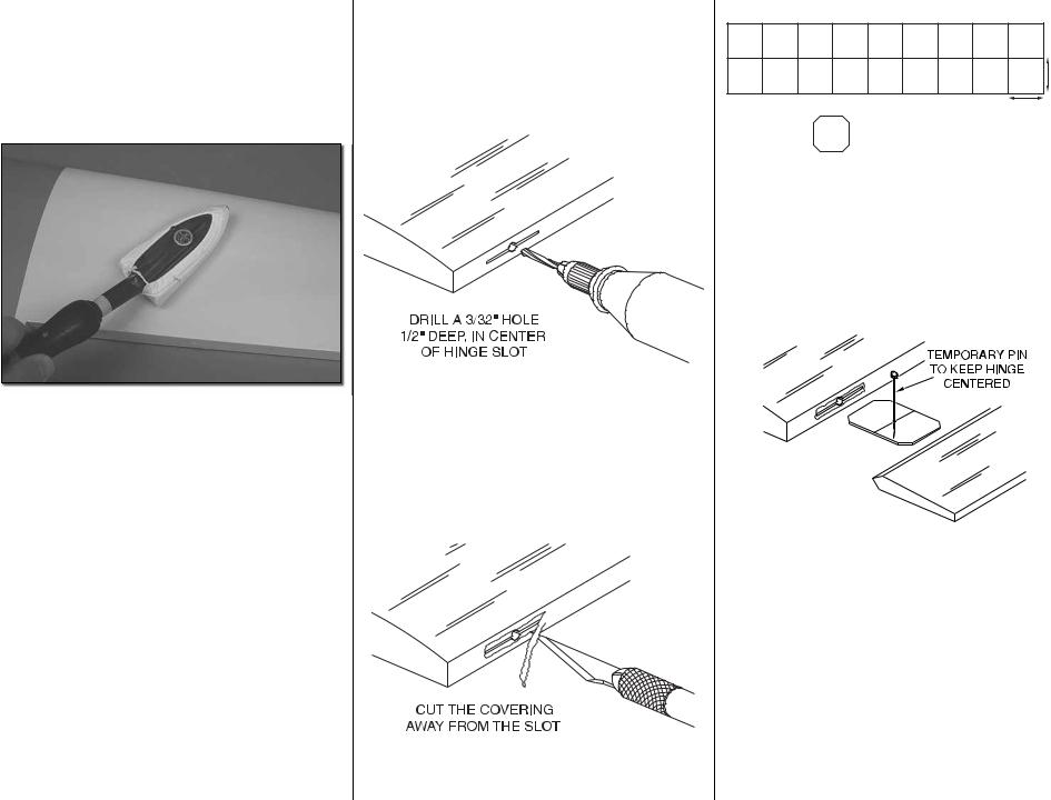
1. Drill a 3/32" hole, 1/2" deep in the center of each hinge slot to allow the CA to ÒwickÓ in. Followup with a #11 blade to clean out the slots. Hint: If you have one, use a high-speed rotary tool to drill the holes.
2.Use a sharp #11 blade to cut a strip of covering from the hinge slots in the wing and aileron.
6
1"
1"
CLIP CORNERS
3. Cut twelve 1" x 1" [25 x 25mm] hinges from a CA hinge strip. Snip off the corners so they go in easier.
4.Test Þ t the aileron to the wing with the hinges. If the hinges donÕt remain centered, stick a pin through the middle of the hinge to hold it in position.
5. Remove any pins you may have inserted into the hinges. Adjust the aileron so there is a small gap between the LE of the aileron and the wing. The gap should be small, just enough to see light through or to slip a piece of paper through.

6. Apply six drops of thin CA to the top and bottom of each hinge. Do not use CA accelerator. After the CA has fully hardened, test the hinges by pulling on the aileron.
7. Locate three hinge point hinges. Apply a drop of oil or apply a small amount of Vaseline into the hinge pin. This will keep glue from getting into the hinge and preventing it from moving freely. Be careful not to get oil on the hinge point. If you do, clean it with a cloth and alcohol.
8. Apply 30-minute epoxy to one side of each hinge and using a toothpick work a small amount of epoxy into each of the holes for the hinge in the leading edge of the ßap. Insert one hinge into each hole.
9. Clean excess epoxy from the hinge and ß ap. Apply epoxy to the other end of the hinge and 7
the holes in the trailing edge of the wing. Insert the ß ap into the wing. Align the hinges with the pivot point in the hinge pocket and so the hinge pivots perpendicular to the leading edge of the ß ap. Be sure the ß ap is pushed close enough to the trailing edge of the wing so the ß ap sits completely ß ush with the bottom of the wing.
10. Set the assembly aside until the glue cures.
11. Repeat steps 1- 10 for the left wing panel.
12. Using the same technique used for the wing ß aps, install four hinges into the ß ap of the wing center section.
13. After the glue has completely cured work the ß ap hinges until they move smoothly.
Did you know…The AT-6 advanced trainer was one of the most widely used aircraft in history. Most AAF fi ghter pilots trained in AT-6s prior to graduation from fl ying school. Many of the “Spitfi re” and “Hurricane” pilots in the Battle of Britain trained in Canada in “Harvards,” the British version of the AT-6.
INSTALL THE AILERON/FLAP SERVOS
AND PUSHRODS
1. Remove the aileron and ß ap covers from the right wing panel.
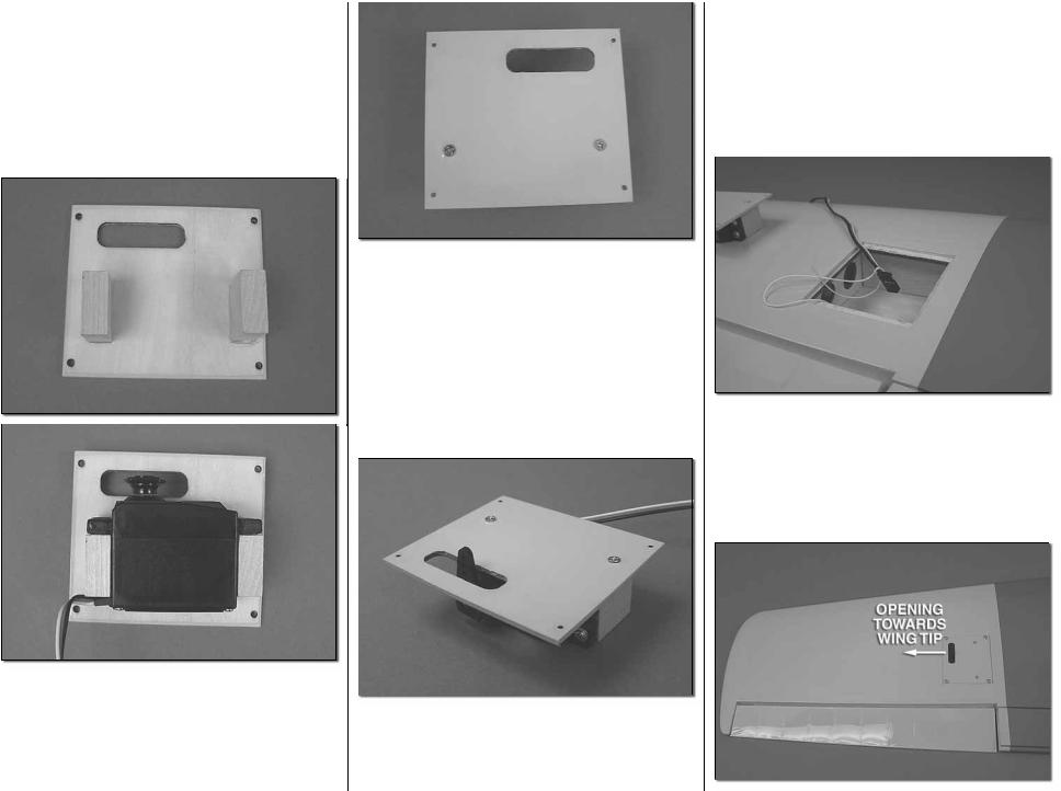
2. Glue two 5/16" x 3/4" x 3/4" [8 x 19 x 19mm] hardwood blocks to the servo cover. Position the blocks so the servo Þ ts between the blocks and the servo horn is centered in the opening.
3. Drill a 1/16" [1.6mm] hole through the servo cover into the center of the servo mounting blocks. Install and then remove a #2 x 3/8" [10mm] wood screw into the holes you drilled. Apply a drop of thin CA into the holes to harden the threads. Once the glue has cured install the screws into the servo cover.
4. Install a 12" servo extension onto the servo lead. Secure the extension to the lead with tape, a piece of shrink tube or some other method to keep them from coming unplugged.
5. Using a 5/64" [2mm] drill bit, enlarge the outer hole on the servo horn. Place the servo onto the servo mounting blocks. Drill through the servo mounting holes with a 1/16" [1.6mm] drill bit. Remove the servo from the servo cover. Install and then
8
remove a servo mounting screw into each of the holes you have drilled. Apply a drop of thin CA into the holes to harden the threads. Once the glue has cured install the servo onto the servo cover using the hardware included with your servo. Center the servo. Then install a servo arm as shown.
6. Inside the servo bay a string is taped. Tie the string to the servo extension. Pull the string and the servo lead through the wing. Do not untie the string from the servo lead.

7. Place the servo cover onto the wing. The opening for the servo arm should be pointed towards the wing tip. Drill a 1/16" [1.6mm] hole through each corner of the cover. Remove the cover. Then install and remove a #2 x 3/8" [10mm] screw into the holes you drilled. Apply a drop of thin CA into the holes to harden the threads. Once the glue has hardened, mount the servo cover with #2 x 3/8" [10mm] screws and #2 ß at washers.
8. Place a nylon control horn in line with the outer hole in the servo arm.When positioned properly the control horn will rest on a hardwood plate in the aileron. Mark the location of the mounting holes onto the aileron. Drill a 1/16" [1.6mm] hole on the marks, drilling through the plywood plate but not through the top of the aileron. Insert and remove a #2 x3/8"
[10mm] screw into each of the holes. Apply a couple drops of thin CA into the holes to harden the threads. Once the glue has hardened attach the horn to the aileron with two #2 x 3/8" [10mm] screws.
9. Screw a nylon clevis onto a .074 x 6" [152mm] threaded wire 20 turns. Slide a nylon clevis retainer onto the clevis. Install the clevis into the second hole from the end of the control horn. Then slide the silicone retainer over the clevis. Center the servo and the aileron. With a Þ ne tip marker, mark the wire where it aligns with the outer hole of the servo arm. Make a 90 degree bend on the mark. Cut the wire so the wire is 3/8" [10mm] in length after the bend. Insert the wire into the servo arm and lock it in place with a nylon Faslink.ª
10. Glue two 5/16" x 3/4" x 3/4" [8 x 19 x 19mm] hardwood blocks to the ß ap servo cover. Position the blocks so the servo Þ ts between the blocks.
11. Drill a 1/16" [1.6mm] hole through the servo cover into the center of the servo mounting blocks. Install and then remove a #2 x 3/8" [10mm] wood screw into the holes you drilled. Apply a drop of thin CA into the holes to harden the threads. Once the glue has cured install the screws into the servo cover.
9
12. Place the servo onto the servo mounting blocks. Drill through the servo mounting holes with a 1/16" [1.6mm] drill bit. Remove the servo from the servo cover. Install and then remove a servo mounting screw into each of the holes you have drilled. Apply a drop of thin CA into the holes to harden the threads. Once the glue has cured install the servo onto the servo cover using the hardware included with your servo. Center the servo and then install a servo arm as shown.
13. Tie the ß ap servo lead to the string with the aileron servo lead. This one string will be used to pull the leads through the wing center section.
14. Place the ß ap servo cover onto the wing. For the right wing the opening for the servo arm should be pointed towards the wing tip. (For the left wing the servo will be located toward the root rib.) Drill a 1/16" [1.6mm] hole through each corner of the cover. Remove the cover. Then install and remove a #2 x 3/8" [10mm] screw into the holes you drilled. Apply a drop of thin CA into the holes to harden the threads. Once the glue has hardened, mount the servo cover with #2 x 3/8" [10mm] screws and #2 ß at washers.

15. Place a nylon control horn in line with the outer hole in the servo arm. Place the nylon control horn backwards from what would be considered the normal mounting position, in line with the outer hole in the servo arm. (This provides better mechanical advantage for the ß ap operation). When positioned properly the control horn will rest on a hardwood plate in the ß ap. Mark the location of the mounting holes onto the ß ap. Drill a 1/16" [1.6mm] hole on the marks, drilling through the plywood plate but not through the top of the ß ap. Insert and remove a #2 x3/8" [10mm] screw into each of the holes. Apply a couple drops of thin CA into the holes to harden the threads. Once the glue has hardened attach the horn to the ß ap with two #2 x 3/8" [10mm] screws.
16. Screw a nylon clevis onto a .074 x 6" [152mm] threaded wire 20 turns. Slide a nylon clevis retainer onto the clevis. Install the clevis into the second hole from the end of the control horn. Then slide the silicone retainer over the clevis. Position the ß ap tight to the bottom of the wing. Position the servo arm so that it is pointed towards the trailing edge of the wing. With a Þ ne tip marker, mark the wire where it aligns with the outer hole of the servo arm. Make a 90 degree bend on the mark. Cut the wire so the wire is 3/8" [10mm] in length after the bend. Insert the wire into the servo arm and lock it in place with a nylon Faslink.
17. Repeat steps 1-15 for the left wing panel.
Important! At step 13 pay close attention to be sure you install the flap servo properly for the left wing.
INSTALL THE WING JOINERS AND
JOIN THE WING HALVES
Important! Be sure to take your time and follow the instructions for installing the wing joiners. Because of the unusual angles of the joiner it can be confusing. Taking your time will insure a proper assembly. It is recommended that you read completely through the instructions and pay attention to the pictures before proceeding with the joiner and joining the wing.
1. Locate two hardwood wing joiners. Slide the joiners completely into the joiner pocket of the wing center section. When you have the joiners matched to the correct side of the wing center section, they will Þ t without force. There will be a slight upward angle of the joiner extending from the center section.
10
 Loading...