

Page 1

Europe, Middle East
ENGLISH
FRANÇAIS
DEUTSCH
NEDERLANDS
ITALIANO
ESPAÑOL
PORTUGUÊS
РУССКИЙ
ČESTINA
TÜRKÇE
POLSKI
SVENSKA
SUOMI
SLOVENCINA
MAGYAR NYELV
תירבע
ﺔﻴﺑﺮﻌﻟا
North America/
Norteamérica
ENGLISH
FRANÇAIS
ESPAÑOL
Latin America/
América Latina
ENGLISH
ESPAÑOL
PORTUGUÊS
Asia Pacic
日本語
简体中文
繁體中文
한국어
ENGLISH
Page 2

1/32
®
For PlayStation
5 consoles and PlayStation®4 consoles
User Manual
Page 3

2/32
TECHNICAL FEATURES
1 T248 base
9 MODE button
10 PS button
2 Wheel rim
3 T-RDD (Thrustmaster Race Dash Display)
screen
4 Encoder selector switch and encoder push
function
5 + and - encoder selector switch
6 2 magnetic paddle shifters (Up and Down)
7 Directional buttons
8 SHARE button on PS4™ consoles
CREATE button on PS5™ consoles
11 DISPLAY button
12 OPTIONS button on PS4™ consoles and
PS5™ consoles
13 Attachment system
14 Metal fastening screw
15 Power cable (EU/US or UK…)
16 Power adapter
17 USB-C (17a) – USB-A (17b) cable
Page 4

3/32
connector for Thrustmaster
18 Large threaded hole (for attachment system
and fastening screw)
19 Threaded holes for attachment to a racing
cockpit (not included)
20 Hook-and-loop fastener cable holder
21 Power adapter connector
22 Racing wheel’s USB-C connector
23 Mini-DIN
shifter, handbrake or hub (sold separately)
24 RJ12 connector for pedal set
Page 5

4/32
WARNING
Information published
Value
Unit
Manufacturer’s name or trademark, commercial
GUILLEMOT CORPORATION S.A.
France Model identifier
A481-1852590D
Input voltage
100 - 240
V
Input AC frequency
50 - 60
Hz
Output voltage
18.5
V
DC
Output current
2.6 A Output power
47.9 W Average active efficiency
87.8 % Efficiency at low load (10%)
87.8 % No-load power consumption
0.10
W
Before using this product, please read this manual carefully and save it for later reference.
Warning – Electrical shock
* Keep the product in a dry location and do not expose it to dust or sunlight.
* Do not twist or pull on the connectors and cables.
* Do not spill any liquid on the product or its connectors.
* Do not short-circuit the product.
* Never dismantle the product; do not throw it onto a fire and do not expose it to high temperatures.
* Do not use a power supply cable other than the one provided with your racing wheel.
* Do not use the power supply cable if the cable or its connectors are damaged, split or broken.
* Make sure that the power supply cable is properly plugged into an electrical outlet, and properly
connected to the connector at the rear of the racing wheel’s base.
* Do not open up the racing wheel: there are no user-serviceable parts inside. Any repairs must be
carried out by the manufacturer, its authorized representative or a qualified technician.
* Only use attachment systems/accessories specified by the manufacturer.
* If the racing wheel is operating abnormally (if it is emitting any abnormal sounds, heat or odors), stop using
it immedi ately, unplug the power supply cable from the electrical outlet and discon nect the other cables.
* If you will not be using the racing wheel for an extended period of time, unplug its power supply cable
from the electrical outlet.
* The electrical outlet must be located near the equipment and must be easily accessible.
Use only the power supply listed in the user instructions.
Information for power supply adapter
registration number and address
414 196 758 Rennes
Place du Granier
BP 97143
35571 Chantepie Cedex
Page 6

5/32
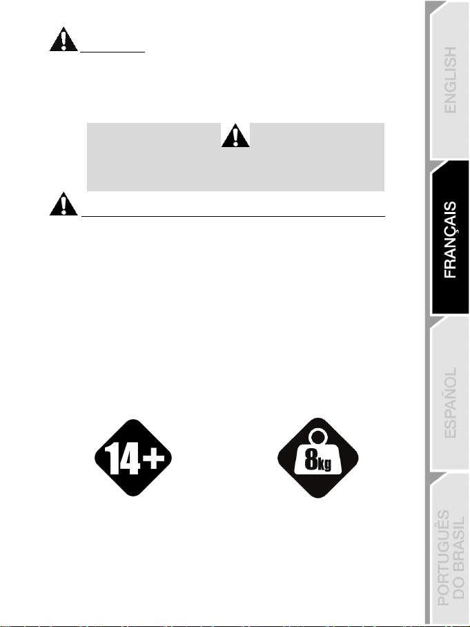
14 years of age or older
HEAVY PRODUCT
yourself or on anyone else!
Air vents
Make sure not to block any of the air vents on the racing wheel’s base. For optimal ventilation, make sure
to do the following:
* Position the wheel’s base at least 10 cm away from any wall surfaces.
* Do not place the base in any tight spaces.
* Do not cover the base.
* Do not let any dust build up on the air vents.
For safety reasons, never use the pedal set with bare feet
or while wearing only socks on your feet.
THRUSTMASTER® DISCLAIMS ALL RESPONSIBILITY IN THE EVENT OF
INJURY RESULTING FROM USE OF THE PEDAL SET WITHOUT SHOES.
Warning – Injuries due to Force Feedback and repeated movements
Playing with a Force Feedback racing wheel may cause muscle or joint pain. To avoid any problems:
* Avoid lengthy gaming periods.
* Take 10 to 15-minute breaks after each hour of play.
* If you feel any fatigue or pain in your hands, wrists, arms, feet or legs, stop playing and rest for a few
hours before you start playing again.
* If the symptoms or pain indicated persist when you start playing again, stop playing and consult your
doctor.
* Keep out of children’s reach.
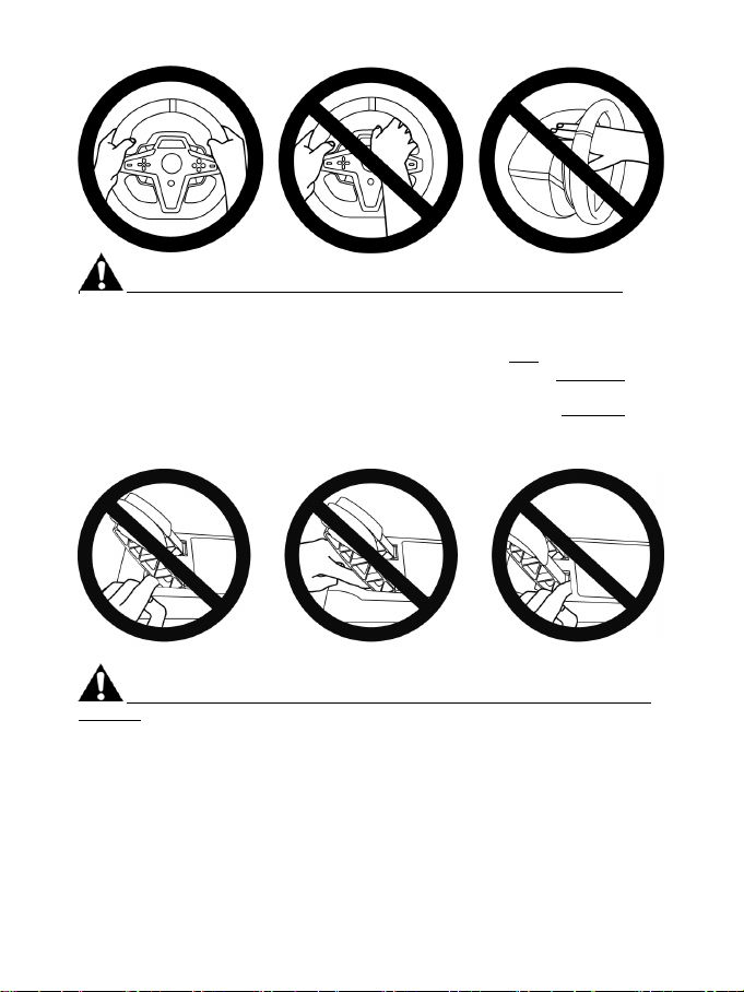
* During gameplay, always leave both hands correctly positioned on the wheel without completely
letting go.
* During gameplay, never place your hands or your fingers under the pedals or anywhere near the
pedal set.
* During calibration and gameplay, never place your hand or your arm through the openings in the
racing wheel.
* Make sure that the racing wheel’s base is properly secured, as per this manual’s instructions.
Product to be handled only by users
Be careful not to drop the product on
Page 7

6/32
ALWAYS NEVER NEVER
Warning – Pedal set pinch hazard when playing
* Keep the pedal set out of children’s reach.
* During gameplay, never place your fingers on or anywhere near the sides of the pedals.
* During gameplay, never place your fingers on or anywhere near the pedal’s rear base.
* During gameplay, never place your fingers on or anywhere near the pedal’s front base.
NEVER NEVER NEVER
Warning – Pedal set pinch hazard when not playing
* Store the pedal set in a safe place, and keep it out of children’s reach.
Page 8

7/32
WARNING: Never tighten the screw alone without the attachment system in place!
(This could damage the racing wheel.)
ATTACHING THE RACING WHEEL
Attaching the racing wheel to a table or a desktop
Start by connecting on the underside of the wheel:
- the power adapter (21);
- the USB-C cable (17a) to the USB-C connector (22);
- the T3PM pedal set (24).
Make sure to follow the paths for the different cables, and attach the cables using the hook-and-loop
fastener cable holder (20).
1. Place the racing wheel on a table or any other horizontal, flat and stable surface.
2. Insert the fastening screw (14) in the attachment system (13), then tighten the device by turning
the screw counterclockwise, so that it feeds into the large threaded hole (18) located beneath the
racing wheel, until the wheel is perfectly stable.
ALWAYS NEVER
Page 9

8/32
ATTACHMENT /
REMOVAL
To tighten:
Turn the screw
counterclockwise
To release:
Turn the screw
clockwise
DIRECTION
Page 10

9/32
Attaching the racing wheel to a racing cockpit (not included)
1. Place the base of the racing wheel on the cockpit’s shelf.
2. Screw two M6 screws (not included) into the cockpit’s shelf and into the two threaded holes on
the underside of the racing wheel (19).
Important
The length of the two M6 screws must not exceed the thickness of the shelf by
more than 0.47 inches/12 mm; longer screws could cause damage to internal
components located in the racing wheel’s base.
3. If necessary, you can also screw the standard attachment system (13, 14) into the large
threaded hole (18).
The T248 racing wheel’s setup diagrams for cockpits and other supports are available at
https://support.thrustmaster.com: click Racing Wheels / T248, and then Template - Cockpit
Setup.
Page 11

10/32
INSTALLATION
AUTOMATIC CALIBRATION OF THE WHEEL
The wheel automatically self-calibrates when you plug the racing wheel into an electrical outlet and
connect the racing wheel’s USB connector to the PlayStation
During this phase, the racing wheel will rotate quickly towards the left and the right, covering a 900
degree angle, before stopping at the center.
Never touch the racing wheel during the self-calibration phase!
(This could result in improper calibration and/or personal injuries.)
WARNING:
5 console or PlayStation4 console.
AUTOMATIC CALIBRATION OF THE PEDAL SET
Never connect the pedal set to the racing wheel’s base (or disconnect it from the base) when it is
connected to the system or during gameplay (this could result in improper calibration).
Always connect the pedal set before connecting the racing wheel to the system.
Once the racing wheel’s calibration is complete and the game has been started, the pedals are
automatically calibrated after a few presses.
Never press the pedals during the racing wheel's
self-calibration phase or while a game is loading!
(This could result in improper calibration.)
WARNING:
If your racing wheel and/or pedal set do not function correctly, or if they seem to be
improperly calibrated:
Power off your console and completely disconnect the racing wheel. Then reconnect all cables
(including the power supply cable and the pedal set), and restart your console and your game.
Page 12

11/32
INSTALLATION ON PLAYSTATION®4 CONSOLES OR PLAYSTATION®5 CONSOLES
1. Plug the power cable and power adapter i nto an electrical outlet.
2. Connect the USB-A cable (17b) to a USB-A port on the PS4™ console or the PS5™ console. Once
the console is powered on, your racing wheel will self-calibrate automatically.
3. Press the PS button (10) on the racing wheel, and sign in to your PlayStation™Network account so
that your racing wheel will be functional.
You are now ready to play!
Please note:
- The list of games compatible with the PlayStation®4 console and the PlayStation®5 console and the
T248 racing wheel is available here: https://support.thrustmaster.com (in the Racing Wheels /
T248 / Games Settings section). This list is updated regularly.
- The racing wheel is recognized in games as a Thrustmaster T-GT racing wheel or a Thrustmaster
Advanced Racer racing wheel.
Page 13

12/32
INSTALLATION ON PC*
* PC functionality not endorsed by Sony Interactive Entertainment Europe and Sony Interactive
Entertainment LLC.
1. Visit https://support.thrustmaster.com to download the drivers and Force Feedback software for
PC. Click Racing Wheels / T248 / Drivers.
2. Plug the power cable and power adapter into an electrical outlet.
3. Connect the USB-A cable (17b) to a USB-A port on your PC.
You are now ready to play!
Please note:
- In the Control Panel and in games, the racing wheel is recognized under the name Thrustmaster
Advanced Racer.
UPDATING THE RACING WHEEL’S FIRMWARE
Visit https://support.thrustmaster.com.
Click Racing Wheels / T248 / Firmware, and follow the instructions.
Page 14

13/32
MAPPING FOR PLAYSTATION®4 CONSOLES OR PLAYSTATION®5
CONSOLES
USING THE E1 / E2 / E3 / E4 ENCODERS
You can select the active encoder by pushing the encoder selector switch (4) up. The active
encoder is displayed on the screen: E1, E2, E3, E4 in succession, and then E1… and so on again.
When the encoder (E1, E2, E3 or E4) is selected, the associated functions are as follows:
- Push (P) by pushing the encoder selector switch (4) down.
- + by pushing the encoder selector switch on the right-hand side (5) up.
- - by pushing the encoder selector switch on the right-hand side (5) down.
The corresponding action is displayed on the screen.
Please note:
- The E1, E2, E3 and E4 encoders function in games compatible with Thrustmaster encoders (F1
2020, F1 2021, Gran Turismo Sport, Assetto Corsa® Competizione, and other upcoming games).
- The screen displaying telemetry information functions in games compatible with the Thrustmaster
SDK. The list of compatible games is available here: https://support.thrustmaster.com (in the
Racing Wheels / T248 / Games Settings section). This list is updated regularly.
Page 15

14/32
MAPPING FOR PC
USING THE E1 / E2 / E3 / E4 ENCODERS
You can select the active encoder by pushing the encoder selector switch (4) up. The active
encoder is displayed on the screen: E1, E2, E3, E4 in succession, and then E1… and so on again.
When the encoder (E1, E2, E3 or E4) is selected, the associated functions are as follows:
- Push (P) by pushing the encoder selector switch (4) down.
- + by pushing the encoder selector switch on the right-hand side (5) up.
- - by pushing the encoder selector switch on the right-hand side (5) down.
The corresponding action is displayed on the screen.
Please note:
- The E1, E2, E3 and E4 encoders function in most games.
- The screen displaying telemetry information functions in games compatible with the Thrustmaster SDK.
The list of compatible games is available here: https://support.thrustmaster.com (in the Racing
Wheels / T248 / Games Settings section). This list is updated regularly.
Page 16

15/32
MODE BUTTON
DISPLAYING INFORMATION ON THE RACING WHEEL, AND CONFIGURING THE RACING WHEEL AND PEDAL
SET
Press the MODE button (9) to enter the MODE menu.
Only the first two segments are displayed when you are in this menu.
Page 17

16/32
Use the directional buttons (7) in this menu as follows:
FFB
DIAGRAM section)
ROT°
automatic)
TEMP
Racing wheel’s motor temperature displayed in
- N: No
screen.
Navigation Screen Information / Options
PS/PC
Select your
system: PS4™
console, PS5™
3 options
3 displays
console or PC
ABOUT
General
information
- Selection of PS4™ console (by default)
- Selection of PS5™ console
- Selection of PC
Note: To validate your system choice,
press the MODE button (9). Selection will
be saved when EXIT appears on screen.
- Firmware v ersion of racing wheel base
- Name of device connected to mini-DIN
connector (23)
- Type of pedal set connected to RJ12
connector (24)
8 levels
3 options
6 options
6 options
2 options
1 display
1 option
Select the Force
Feedback profile
(see FFB
PROFILE
FORCE
Select the overall
wheel’s force effect
level
Select the angle of
rotation
(only for games in
which the angle of
rotation is not
PEDAL
Select the pedal
set configuration
Motor temperature
RESET
Reset the racing
wheel to default
mode.
- FFB 1
- FFB 2 (by default)
- FFB 3
- 270°
- 360°
- 540°
- 720°
- 900°
- AUTO = Automatic (by default)
- FLOOR: floor position (by default)
- INV.: suspended position
(the accelerator and clutch pedals are
reversed)
real time
- Y: Yes
Select Y, then press the MODE button (9). The
racing wheel is reset when EXIT appears on
Page 18

17/32
FORCE
Allows to adjust in real time (= directly in race) all the racing wheel’s force effects, from 20 to 100%.
FFB (FFB 1 / FFB 2 / FFB 3) PROFILE DIAGRAM
FFB 1
The FFB 1 effect provides linear Force Feedback. The force that you feel is 100% proportional to the
force requested by the game.
FFB 2 and FFB 3
The FFB 2 and FFB 3 effects boost the Force Feedback in order to accentuate the force that you feel
in relation to the force requested by the game.
Please note:
- Validate your choices by pressing the MODE button (9): EXIT is displayed before returning to your
default screen.
- The directional buttons (7) are disabled in games and in the console’s interface when the MODE
button is enabled.
Page 19

18/32
DISPLAY BUTTON
CONFIGURING THE DISPLAY OF TELEMETRY SETTINGS
(in compatible games)
Please note:
- The list of games compatible with the T-RDD (Thrustmaster Race Dash Display) screen is available
here: https://support.thrustmaster.com (in the Racing Wheels / T248 / Games Settings section). This
list is updated regularly.
- The DISPLAY button only works in these games.
Press the DISPLAY button (11) to enter the DISPLAY menu.
Only the last two segments are displayed when you are in this menu.
Page 20

19/32
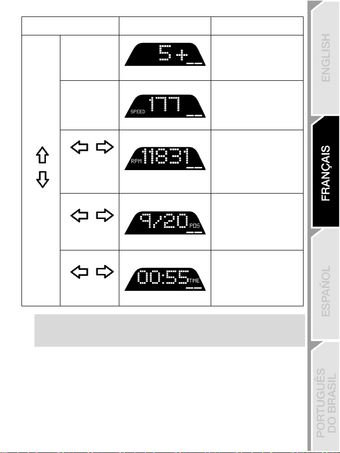
- REV >>: left to right
segments
Use the directional buttons (7) in this menu as follows:
Navigation Screen Information / Options
No
Shifter
SPEED
- REV <<: right to left
- REV ><: outside toward
center
- REV <>: center toward
outside
- REV --: no display on the
5 levels
No
5 options for display
across the segments
Speed
RPM
RPM and choice of view
across the 9 segments
POS
- DRI: position in the race
2 options
Position
TIME
3 options
Please note:
- Validate your choices by pressing the DISPLAY button (11).
- The directional buttons (7) are disabled in games and in the console’s interface when the DISPLAY
button is enabled.
Time
- LAP: number of laps
- PBL: best personal lap
time
- C L: current lap time
- L L: last lap time
Page 21

20/32
VARIOUS TIPS AND FAQs
Visit https://support.thrustmaster.com. Click Racing Wheels / T248, and then Manual or FAQ.
Page 22

21/32
T3PM PEDAL SET
Page 23

22/32
TECHNICAL FEATURES
1 Pedal set
5 Upper retaining head with washer
6 Elastomer cushioning ring (white – Shore 70)
2 Additional hard spring (black)
3 2.5 mm Allen key
4 Spring retaining rod
7 Upper plastic spacer (red)
8 Soft spring (silver – installed by default)
9 Lower plastic spacer (red)
Page 24

23/32
NEVER
NEVER
NEVER
WARNING
Before using this product, please read this manual carefully and save it for later reference.
For safety reasons, never use the pedal set with bare feet
THRUSTMASTER® DISCLAIMS ALL RESPONSIBILITY IN THE EVENT OF
* Keep the pedal set out of children’s reach.
* During gameplay, never place your fingers on or anywhere near the sides of the pedals.
* During gameplay, never place your fingers on or anywhere near the pedal’s rear base.
* During gameplay, never place your fingers on or anywhere near the pedal’s front base.
INJURY RESULTING FROM USE OF THE PEDAL SET WITHOUT SHOES.
Warning – Pedal set pinch hazard when playing
or while wearing only socks on your feet.
Page 25

24/32
AUTOMATIC CALIBRATION OF THE PEDAL SET
- Never connect the pedal set to the racing wheel’s base (or disconnect it from the base) when it is
connected to the PS4™ console or PS5™ console, or during gameplay (this could result in
improper calibration).
Always connect the pedal set before connecting the racing wheel to the console.
- Once the racing wheel’s calibration is complete and the game has been started, the pedals are
automatically calibrated after a few presses.
- Never press the pedals during the racing wheel's self-calibration phase or while a game is loading!
This could result in improper calibration.
If your racing wheel and/or pedal set do not function correctly, or if they seem to be
improperly calibrated:
Power off your console and completely disconnect the racing wheel. Then reconnect all cables
(including the power supply cable and the pedal set), and restart your console and your game.
IMPORTANT
Page 26

25/32
ATTACHING THE PEDAL SET TO A SUPPORT OR COCKPIT
The pedal set can be attached to a variety of different compatible supports (sold separately) using
the five M6-type threaded holes located underneath the base. To do so, screw at least two M6
screws (not included) through the support shelf, and into the threaded holes on the underside of the
pedal set’s base.
Important: the length of the M6 screws must not exceed the thickness of your support by
more than 0.47 inches/12 mm, so as not to risk damaging the pedal set’s internal
The pedal set’s setup diagrams for cockpits and other supports are available at
https://support.thrustmaster.com: click Racing Wheels / T3PM, and then Template - Cockpit
setup.
components.
Page 27

26/32
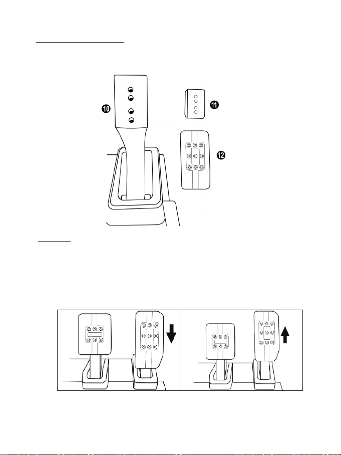
ADJUSTING THE PEDAL SET
Low position
High position (default)
Each of the three pedals includes:
- A pedal arm (10) with two perforations.
- A plastic head support (11) (placed between the head and the arm) with four perforations.
- A metal head (12) with multiple perforations (nine for the accelerator – six for the brake – six for
the clutch).
ATTENTION: To avoid any calibration problems, be sure to always disconnect your wheel’s
USB cable from the console or PC before making any adjustments to your pedal set.
Adjusting the HEIGHT of the gas pedal
- Using the included 2.5 mm Allen key (3), unscrew the two screws holding the metal head (12) and
its support ( 11) in place.
- Select your preferred height position, then replace and re-tighten the screws so that the metal
head (12) and its support (11) are held firmly in place.
Page 28

27/32
(default)
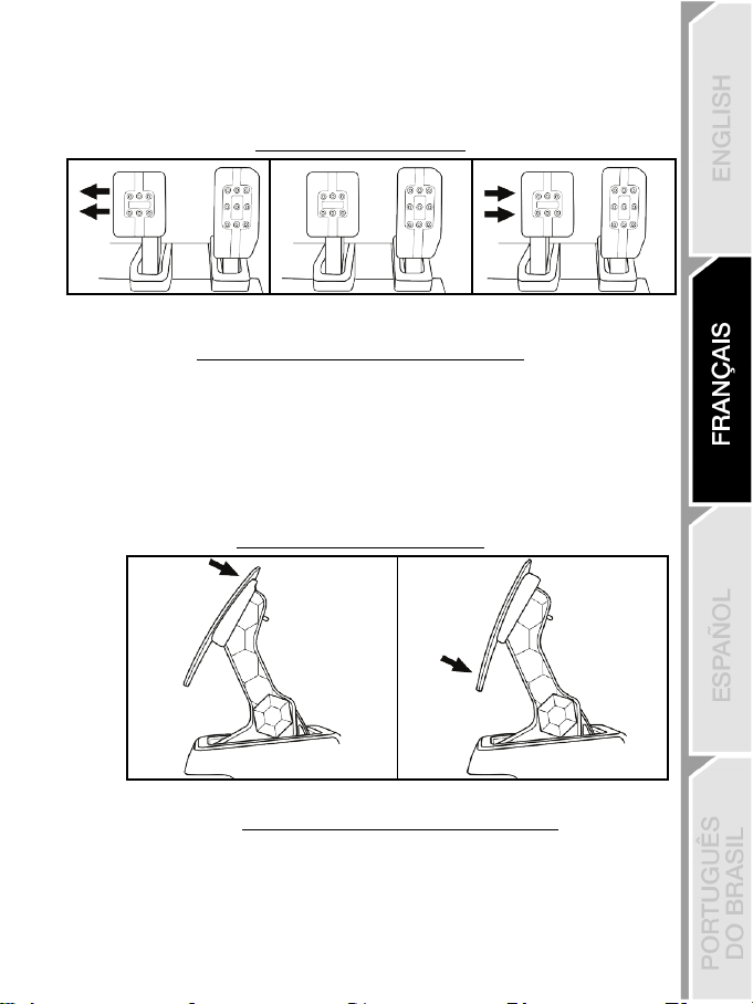
Adjusting the SPACING of the three pedals
- Using the included 2.5 mm Allen key (3), unscrew the two screws holding the metal head (12) and
its support (11) in place.
- Select your preferred position (to the left, centered, or to the right), then replace and re-tighten the
screws so that the metal head (12) and its support (11) are held firmly in place.
Examples illustrating the brake pedal:
Left position Centered position
Number of possible spacing positions per pedal:
- Three for gas pedal
- Three for brake pedal
- Three for clutch pedal
Right position
Adjusting the INCLINATION of the pedals
- Using the included 2.5 mm Allen key (3), unscrew the two screws holding the metal head (12) and
its support ( 11) in place.
- Turn the plastic head support (11) 180°, then replace and re-tighten the screws so that the metal
head (12) and its support (11) are held firmly in place.
Examples illustrating the gas pedal:
Less inclined position (default) More inclined position
Number of possible inclination positions per pedal:
- Two for gas pedal
- Two for brake pedal
- Two for clutch pedal
Page 29

28/32
INCLUDED SET OF BRAKE SPRINGS
Medium
(by default)
Pedal set
support
Soft silver spring (8)
x
x
White elastomer cushioning
ring (6)
x x
Hard black spring (2)
x x
4 possible configurations and settings for the brake pressure force
This mod lets you experience a different feel and resistance when braking.
You can choose to install it or not, according to your preferences.
Brake resistance Soft
Hard Very hard
Recommended use Desk Desk
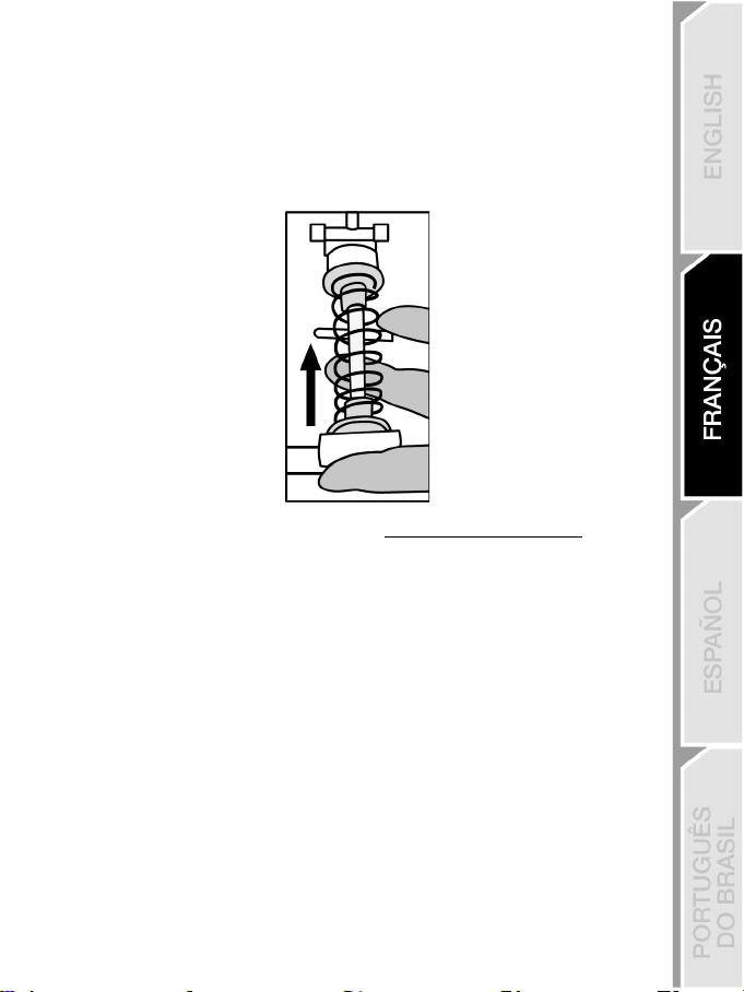
1. Pull hard on the lower plastic spacer (9) to compress the spring and remove the spring retaining
rod (4) from its location.
Method 1:
Method 2:
Cockpit
Page 30

29/32
2. Reposition the different elements on the spring retaining rod (4).
Start with the lower plastic spacer (9), your choice of spring (2) or (8), and then the upper plastic
spacer (7).
3. After your selected configuration, install the elastomer cushioning ring (6).
4. Adjust the upper retaining head with washer (5) and position it in its location.
5. Strongly compress the spring in order to place the spring retaining rod (4) in its location
A video showing how to change the spring is available at https://support.thrustmaster.com: click
Racing Wheels / T3PM.
Page 31

30/32
CONSUMER WARRANTY INFORMATION
Worldwide, Guillemot Corporation S.A., whose registered office is located at Place du Granier, B.P. 97143,
35571 Chantepie, France (hereinafter “Guillemot”) warrants to the consumer that this Thrustmaster product shall
be free from defects in materials and workmanship, for a warranty period which corresponds to the time limit to
bring an action for conformity with respect to this product. In the countries of the European Union, this
corresponds to a period of two (2) years from delivery of the Thrustmaster product. In other countries, the
warranty period corresponds to the time limit to bring an action for conformity with respect to the Thrustmaster
product according to applicable laws of the country in which the consumer was domiciled on the date of
purchase of the Thrustmaster product (if no such action exists in the corresponding country, then the warranty
period shall be one (1) year from the original date of purchase of the Thrustmaster product).
Should the product appear to be defective during the warranty period, immediately contact Technical Support,
who will indicate the procedure to follow. If the defect is confirmed, the product must be returned to its place of
purchase (or any other location indicated by Technical Support).
Within the context of this warranty, the consumer’s defective product shall, at Technical Support’s option, be
either replaced or returned to working order. If, during the warranty period, the Thrustmaster product is subject to
such reconditioning, any period of at least seven (7) days during which the product is out of use shall be added
to the remaining warranty period (this period runs from the date of the consumer’s request for intervention or
from the date on which the product in question is made available for reconditioning, if the date on which the
product is made available for reconditioning is subsequent to the date of the request for intervention). If permitted
under applicable law, the full liability of Guillemot and its subsidiaries (including for consequential damages) is
limited to the return to working order or the replacement of the Thrustmaster product. If permitted under
applicable law, Guillemot disclaims all warranties of merchantability or fitness for a particular purpose.
This warranty shall not apply: (1) if the product has been modified, opened, altered, or has suffered damage as a
result of inappropriate or abusive use, negligence, an accident, normal wear, or any other cause unrelated to a
material or manufacturing defect (including, but not limited to, combining the Thrustmaster product with any
unsuitable element, including in particular power supplies, rechargeable batteries, chargers, or any other
elements not supplied by Guillemot for this product); (2) if the product has been used for any use other than
home use, including for professional or commercial purposes (game rooms, training, competitions, for example);
(3) in the event of failure to comply with the instructions provided by Technical Support; (4) to software, said
software being subject to a specific warranty; (5) to consumables (elements to be replaced over the product’s
lifespan: disposable batteries, audio headset or headphone ear pads, for example); (6) to accessories (cables,
cases, pouches, bags, wrist-straps, for example); (7) if the product was sold at public auction.
This warranty is nontransferable.
The consumer’s legal rights with respect to laws applicable to the sale of consumer goods in his or her country
are not affected by this warranty.
Additional warranty provisions
During the warranty period, Guillemot shall not provide, in principle, any spare parts, as Technical Support is the
only party authorized to open and/or recondition any Thrustmaster product (with the exception of any
reconditioning procedures which Technical Support may request that the consumer carry out, by way of written
instructions – for example, due to the simplicity and the lack of confidentiality of the reconditioning process – and
by providing the consumer with the required spare part(s), where applicable).
Given its innovation cycles and in order to protect its know-how and trade secrets, Guillemot shall not provide, in
principle, any reconditioning notification or spare parts for any Thrustmaster product whose warranty period has
expired.
In the United States of America and in Canada, this warranty is limited to the product’s internal mechanism and
external housing. In no event shall Guillemot or its affiliates be held liable to any third party for any consequential
or incidental damages resulting from the breach of any express or implied warranties. Some States /Provinces do
not allow limitation on how long an implied warranty lasts or exclusion or limitation of liability for consequential or
incidental damages, so the above limitations or exclusions may not apply to you. This warranty gives you
specific legal rights, and you may also have other rights which vary from State to State or Province to Province.
Page 32

31/32
TECHNICAL SUPPORT
Canada: 866-889-2181
Liability
If permitted under applicable law, Guillemot Corporation S.A. (hereinafter “Guillemot”) and its subsidiaries
disclaim all liability for any damages caused by one or more of the following: (1) the product has been modified,
opened or altered; (2) failure to comply with assembly instructions; (3) inappropriate or abusive use, negligence,
an accident (an impact, for example); (4) normal wear; (5) the use of the product for any use other than home
use, including for professional or commercial purposes (game rooms, training, competitions, for example). If
permitted under applicable law, Guillemot and its subsidiaries disclaim all liability for any damages unrelated to a
material or manufacturing defect with respect to the product (including, but not limited to, any damages caused
directly or indirectly by any software, or by combining the Thrustmaster product with any unsuitable element,
including in particular power supplies, rechargeable batteries, chargers, or any other elements not supplied by
Guillemot for this product).
DECLARATION OF CONFORMI TY
CANADIAN COMPLIANCE NOTICE: this Class B digital apparatus meets all requirements of the Canadian
Interference-Causing Equipment Regulations.
USA COMPLIANCE NOTICE: this equipment has been tested and found to comply with the limits for a Class B
digital device, pursuant to Part 15 of the FCC rules. Operation is subject to the following two conditions:
(1) This device may not cause harmful interference, and
(2) This device must accept any interference received, including interference that may cause undesired
operation.
These limits are designed to provide reasonable protection against harmful interference in a residential
installation. This equipment generates, uses and can radiate radio frequency energy and, if not installed and
used in accordance with the instructions, may cause harmful interference to radio communications. However,
there is no guarantee that interference will not occur in a particular installation. If this equipment does cause
harmful interference to radio or television reception, which can be determined by turning the equipment on and
off, the user is encouraged to try to correct the interference by one or more of the following measures:
- Reorient or relocate the receiving antenna.
- Increase the separation between the equipment and receiver.
- Connect the equipment into an outlet on a circuit different from that to which the receiver is connected.
- Consult the dealer or an experienced radio/TV technician for help.
https://support.thrustmaster.com
UK: 020 3147 4889
US: (866) 889-5036
Page 33

32/32
COPYRIGHT
*
*
©2022 Guillemot Corporation S.A. All rights reserved. Thrustmaster® is a registered trademark of
Guillemot Corporation S.A. Manufactured and distributed by Guillemot Corporation S.A. All other
trademarks and brand names are hereby acknowledged and are the property of their respective
owners. Contents, design, and specifications are subject to changes without notice and may vary
from one country to another. Photos and illustrations not binding. Designed in North America and
Europe, made in Chin a.
For use exclusively with PlayStation
“1”, “PlayStation”, “PS5”, “PS4” and “PlayStation Shapes Logo” are registered trademarks or
trademarks of Sony Interactive Entertainment Inc. All rights reserved. All other trademarks are the
property of their respective owners. Manufactured and distributed under license from Sony
Interactive Entertainment LLC.
WARNING: this product can expose you to chemicals including Bisphenol A (BPA), which is
known to the State of California to cause birth defects or other reproductive harm. For more
information go to www.P65Warnings.ca.gov
ENVIRONMENTAL PROTECTION RECOMMENDATION
In the European Union, the UK and Turkey: At the end of its working life, this product
should not be disposed of with standard household waste, but rather dropped off at
a collection point for the disposal of Waste Electrical and Electronic Equipment
(WEEE) for recycling.
This is confirmed by the symbol found on the product, user manual or packaging.
Depending on their characteristics, the materials may be recycled. Through recycling
and other forms of processing Waste Electrical and Electronic Equipment, you can
Please contact your local authorities for information on the collection point nearest you.
For all other countries: Please adhere to local recycling laws for electrical and electronic equipment.
Retain this information. Colors and decorations may vary.
Plastic fasteners and adhesives should be removed from the product before it is used.
www.thrustmaster.com
*Applicable to EU, UK and Turkey only
make a significant contribution towards helping to protect the environment.
®5 consoles and PlayStation®4 consoles.
Page 34

1/32
®
Pour consoles PlayStation
5 et consoles PlayStation®4
Manuel de l’utilisateur
Page 35

2/32
CARACTÉRISTIQUES TECHNIQUES
1 Base T248
9 Bouton MODE
10 Bouton PS
2 Roue du volant
3 Ecran T-RDD (Thrustmaster Race Dash
Display)
4 Sélecteur encodeur et fonction encodeur push
5 Encodeur + et -
6 2 palettes de vitesses magnétiques (Up et
Down)
7 Boutons directionnels
8 Bouton SHARE sur consoles PS4™
Bouton CREATE sur consoles PS5™
11 Bouton DISPLAY
12 Bouton OPTIONS sur consoles PS4™ et
consoles PS5™
13 Système de fixation
14 Vis de serrage métallique
15 Câble d’alimentation (EU/US ou UK…)
16 Adaptateur secteur
17 Câble USB-C (17a) – USB-A (17b)
Page 36

3/32
21 Connecteur pour l’adaptateur secteur
24 Connecteur RJ12 pour le pédalier
18 Gros pas de vis (pour le système de fixation
et la vis de serrage)
19 Pas de vis pour fixation cockpit (non inclus)
20 Serre-câble auto-agrippant
22 Connecteur USB-C du volant
23 Connecteur mini-DIN pour la boîte de
vitesses, le frein à main ou le hub
Thrustmaster (vendus séparément)
Page 37

4/32
AVERTISSEMENTS
Informations publiées
Valeur
Unité
Nom ou marque du fabricant
GUILLEMOT CORPORATION S.A.
France Identifiant du modèle
A481-1852590D
Tension d'entrée
100 - 240
V
Fréquence AC d'entrée
50 - 60
Hz
Tension de sortie
18,5
V CC
Courant de sortie
2,6 A Puissance de sortie
47,9 W Efficacité active moyenne
87,8 % Efficacité en charge faible (10 %)
87,8 % Consommation électrique sans charge
0,10
W
Avant d’utiliser ce produit, lisez attentivement cette documentation et conservez-la pour pouvoir la
consulter ultérieurement.
Avertissement – Choc électrique
* Conservez le produit dans un endroit sec et ne l’exposez ni à la poussière ni au soleil.
* Ne tordez pas et ne tirez pas sur les connecteurs et câbles.
* Ne renversez pas de liquide sur le produit et ses connecteurs.
* Ne mettez pas le produit en court-circuit.
* Ne démontez jamais le produit, ne le jetez pas au feu et ne l’exposez pas à des températures élevées.
* N’utilisez pas de câble d’alimentation autre que celui fourni avec votre volant.
* N’utilisez pas le câble d’alimentation secteur si celui-ci où ses connecteurs sont endommagés, fendus
ou cassés.
* Assurez-vous que le câble d’alimentation secteur est parfaitement inséré dans la prise murale et dans
son connecteur situé à l’arrière de la base du volant.
* N’ouvrez pas l’appareil. L’appareil ne contient pas de pièces réparables par l'utilisateur. Confiez toute
réparation au fabricant, à une agence spécifiée ou un technicien qualifié.
* Utilisez uniquement les systèmes de fixation /accessoires spécifiés par le fabricant.
* Si le volant fonctionne de manière anormale (s’il émet des sons, de la chaleur ou des odeurs
anormales), arrêtez immédiatement de l’utiliser, débranchez le câble d’alimentation de la prise
électrique et déconnectez les autres câbles.
* Lorsque vous n’utilisez pas le volant pendant une période prolongée, débranchez le câble
d’alimentation secteur de la prise électrique.
* La prise électrique doit être située à proximité de l’équipement et doit être facilement accessible.
Utilisez uniquement le bloc d’alimentation listé dans le manuel de l’utilisateur.
Information relative au bloc d’alimentation
Numéro d'entreprise
Adresse
414 196 758 Rennes
Place du Granier
BP 97143
35571 Chantepie Cedex
Page 38
5/32
personnes âgées de 14 ans ou plus
PRODUIT LOURD
une autre personne
Grilles d’aération
Veuillez à n’obstruer aucune grille d’aération de la base du volant. Pour assurer une ventilation optimale,
respectez les points ci-après :
* Placez la base à 10 cm au moins d’une surface murale.
* Ne placez pas la base dans un endroit exigu.
* Ne couvrez pas la base.
* Ne laissez pas la poussière s’accumuler sur les grilles d’aération.
Pour des raisons de sécurité, ne jouez pas pieds nus ou en chaussettes
lorsque vous utilisez le pédalier.
THRUSTMASTER® DECLINE TOUTE RESPONSABILITE EN CAS DE
BLESSURE SUITE A UNE UTILISATION DU PEDALIER SANS CHAUSSURES.
Avertissement – Blessures dues au retour de force et aux mouvements répétitifs
Jouer avec un volant à retour de force peut causer des douleurs aux muscles et aux articulations. Afin
d’éviter tout problème :
* Evitez les périodes trop longues de jeu.
* Faites une pause de 10 à 15 minutes après chaque heure de jeu.
* Si vous éprouvez fatigue ou douleur au niveau des mains, des poignets, des bras, des pieds ou des
jambes, cessez de jouer et reposez-vous pendant quelques heures avant de recommencer à jouer.
* Si les symptômes ou les douleurs indiqués ci-dessus persistent lorsque vous reprenez le jeu, arrêtez
de jouer et consultez votre médecin.
* Laissez hors de portée des enfants.
* Lors des phases de jeu, laissez toujours vos deux mains correctement positionnées sur le volant
sans jamais le lâcher complètement.
* Lors des phases de jeu, ne placez jamais vos mains ou vos doigts sous les pédales ou à proximité
du pédalier.
* Lors des phases de calibration et de jeu, ne jamais introduire une main ou un bras à l’intérieur de la
roue du volant.
* Vérifiez que la base du volant est correctement fixée, conformément aux instructions du manuel.
Produit à manipuler uniquement par des
Ne pas laisser tomber le produit sur vous ou
Page 39
6/32
TOUJOURS JAMAIS JAMAIS
Avertissement – Risque de pincement au niveau du pédalier lors des phases de jeu
* Laissez le pédalier hors de portée des enfants.
* Lors des phases de jeu, ne placez jamais vos doigts sur ou à proximité des côtés des pédales.
* Lors des phases de jeu, ne placez jamais vos doigts sur ou à proximité de la base arrière des
pédales.
* Lors des phases de jeu, ne placez jamais vos doigts sur ou à proximité de la base avant des
pédales.
JAMAIS JAMAIS JAMAIS
Avertissement – Risque de pincement au niveau du pédalier lorsque vous n’utilisez pas
le pédalier
* Placez le pédalier dans un endroit sûr et hors de portée des enfants.
Page 40

7/32
ATTENTION : Ne jamais visser la vis de serrage seule sans le système de fixation !
(au risque de détériorer le volant).
FIXATION DU VOLANT
Fixer le volant sur une table ou un bureau
Commencez par connecter sous le volant :
- l’adaptateur secteur (21),
- le câble USB-C (17a) dans le connecteur USB C (22),
- le pédalier T3PM (24).
Veillez à suivre les chemins de câbles et à attacher les câbles à l’aide du serre-câble (20) prévu à
cet effet.
1. Placez le volant sur une table ou autre surface plane.
2. Placez la vis de serrage (14) dans le système de fixation (13), puis vissez l’ensemble (dans le
sens inverse des aiguilles d’une montre) dans le gros pas de vis (18) situé sous le volant, jusqu’à
ce que ce dernier soit parfaitement stable.
TOUJOURS JAMAIS
Page 41

8/32
MONTAGE /
DEMONTAGE
Pour serrer :
dans le sens
des aiguilles d’une
Pour desserrer :
Dévissez
dans le sens
des aiguilles d’une
SENS
Vissez
inverse
montre
montre
Page 42
9/32
Fixer le volant sur un cockpit (non inclus)
1. Placez la base du volant sur la tablette du cockpit.
2. Vissez 2 vis M6 (non fournies) dans la tablette du cockpit et dans les 2 pas de vis situés sous le
volant (19).
Important
La longueur des vis M6 ne doit pas dépasser l’épaisseur de votre support
+12 mm afin de ne pas endommager les composants internes de la base.
3. Si nécessaire, vissez en plus le système de fixation classique (13, 14) dans le gros pas de vis (18).
Le plan d’implantation du T248 pour les supports est disponible sur
https://support.thrustmaster.com : cliquez sur Volants / T248, puis sur Template - Cockpit
Setup.
Page 43

10/32
INSTALLATION
CALIBRAGE AUTOMATIQUE DU VOLANT
La roue du volant s’autocalibre de manière automatique une fois le volant relié au secteur et le
connecteur USB connecté à la console PlayStation
Cette opération entraîne des mouvements rapides du volant de gauche à droite sur 900° avant de
s’immobiliser au centre.
Lors des phases d’autocalibration de la roue du volant, ne jamais toucher au volant
(au risque de fausser la calibration ou de se blesser).
®5 ou la console PlayStation4.
ATTENTION :
CALIBRAGE AUTOMATIQUE DES PEDALES
Ne jamais débrancher ou brancher le pédalier de la base du volant lorsque celui-ci est connecté à la
console ni en cours de jeu (pour ne pas fausser la calibration)
= le pédalier doit toujours être branché avant de relier le volant à la console.
Une fois le volant autocalibré et le jeu lancé, les pédales se calibrent automatiquement après quelques
pressions.
Lors des phases d’autocalibration de la roue du volant et lorsque votre jeu se lance,
ATTENTION :
ne jamais appuyer sur les pédales
(au risque de fausser la calibration)
Si votre volant et vos pédales ne fonctionnent pas correctement ou semblent mal calibrés :
Eteignez votre console, déconnectez entièrement votre volant, reconnectez tous les câbles (avec le
câble d’alimentation secteur et le pédalier), redémarrez et relancez votre jeu.
Page 44

11/32
INSTALLATION SUR CONSOLES PLAYSTATION®4 OU SUR CONSOLES
PLAYSTATION
1. Branchez l’adaptateur secteur sur une prise de courant.
2. Branchez le câble USB A (17b) sur un port USB A de la console PS4™ ou de la console PS5™.
Une fois votre console allumée, votre volant s’autocalibre de manière automatique.
3. Appuyez sur le bouton PS (10) du volant, puis connectez-vous à votre compte PlayStation™Network
pour que votre volant soit fonctionnel.
us êtes maintenant prêt à jouer !
Vo
Remarques :
- La liste des jeux compatibles avec la console PlayStation®4 et la console PlayStation®5 et le T248 est
disponible ici : https://support.thrustmaster.com (dans la rubrique Volants / T248 / Paramètres de
jeux). Cette liste est régulièrement mise à jour.
- Le volant est reconnu dans les jeux comme un volant Thrustmaster T-GT ou un volant
Thrustmaster Advanced Racer.
®5
Page 45

12/32
INSTALLATION SUR PC*
*Fonctionnalité PC non endossée par Sony Interactive Entertainment Europe et Sony Interactive
Entertainment LLC.
1. Allez sur https://support.thrustmaster.com
pour PC. Cliquez sur Volants / T248 puis Pilotes.
2. Branchez l’adaptateur secteur sur une prise de courant.
3. Branchez le câble USB A (17b) sur un port USB A de votre PC.
pour télécharger les pilotes et le logiciel Force Feedback
Vous êtes maintenant prêt à jouer !
Remarque :
- Dans le Panneau de configuration et dans les jeux, le volant est connu sous le nom Thrustmaster
Advanced Racer.
METTRE A JOUR LE FIRMWARE DU VOLANT
Aller sur https://support.thrustmaster.com
Cliquez sur Volants / T248 / Firmware puis suivez les instructions.
.
Page 46

13/32
MAPPING POUR CONSOLES PLAYSTATION®4 OU CONSOLES
PLAYSTATION
UTILISATION DES ENCODEURS E1 / E2 / E3 / E4
Vous pouvez choisir l’encodeur actif en actionnant le sélecteur encodeur (4) vers le haut. L’encodeur
actif s’affiche à l’écran : successivement E1, E2, E3, E4, puis de nouveau E1…
Lorsque l’encodeur (E1, E2, E3 ou E4) est sélectionné, les fonctions associées sont les suivantes :
- Push (P) en actionnant le sélecteur encodeur (4) vers le bas.
- + en actionnant l’encodeur droit (5) vers le haut.
- - en actionnant l’encodeur droit (5) vers le bas.
L’action correspondante s’affiche à l’écran.
Remarques :
- Les encodeurs E1, E2, E3, E4 fonctionnent dans les jeux compatibles avec les encodeurs Thrustmaster
(F1 2020, F1 2021, Gran Turismo Sport, Assetto Corsa® Competizione et d’autres jeux bientôt
disponibles).
- L’écran affichant les informations de télémétrie fonctionne dans les jeux compatibles avec le SDK
Thrustmaster. La liste des jeux compatibles est disponible ici : https://support.thrustmaster.com (dans
la rubrique Volants / T248 / Paramètres de jeux). Cette liste est régulièrement mise à jour.
®5
Page 47

14/32
MAPPING POUR PC
UTILISATION DES ENCODEURS E1 / E2 / E3 / E4
Vous pouvez choisir l’encodeur actif en actionnant le sélecteur encodeur (4) vers le haut. L’encodeur
actif s’affiche à l’écran : successivement E1, E2, E3, E4, puis de nouveau E1…
Lorsque l’encodeur (E1, E2, E3 ou E4) est sélectionné, les fonctions associées sont les suivantes :
- Push (P) en actionnant le sélecteur encodeur (4) vers le bas.
- + en actionnant l’encodeur droit (5) vers le haut.
- - en actionnant l’encodeur droit (5) vers le bas.
L’action correspondante s’affiche à l’écran.
Remarques :
- Les encodeurs E1, E2, E3, E4 fonctionnent dans la plupart des jeux.
- L’écran affichant les informations de télémétrie fonctionne dans les jeux compatibles avec le SDK
Thrustmaster. La liste des jeux compatibles est disponible ici : https://support.thrustmaster.com (dans
la rubrique Volants / T248 / Paramètres de jeux). Cette liste est régulièrement mise à jour.
Page 48

15/32
BOUTON MODE
AFFICHAGE DES INFORMATIONS SUR LE VOLANT ET CONFIGURATION DU VOLANT ET DU PÉDALIER
Un appui sur le bouton MODE (9) permet d’entrer dans le menu MODE.
Seuls les 2 premiers segments sont affichés tant que vous vous trouvez dans ce menu.
Page 49

16/32
Utilisez les boutons directionnels (7) comme suit dans ce menu :
- Choix de la console PS4™ (par défaut)
le menu et que EXIT s’affiche.
3 affichages
6 options
3 options
ROT°
automatique)
- 270°
- AUTO = Automatique (par défaut)
TEMP
Température du moteur
Affichage de la température du moteur en
temps réel
- N : No
vous quittez le menu et que EXIT s’affiche.
Navigation Ecran Informations / Options
8 niveaux
3 options
6 options
2 options
1 affichage
1 option
PS/PC
Choix du système : console
PS4™, console PS5™
ou PC
ABOUT
Informations générales
FORCE
Choix de la force générale
du volant
FFB
Choix du profil de retour de
force (cf. COURBES FFB)
Choix de l’angle de rotation.
(uniquement pour les jeux
dans lesquels l’angle de
rotation n’est pas
PEDAL
Choix de la configuration du
pédalier
RESET
Pour reconfigurer le volant
en mode « par défaut ».
- Choix de la console PS5™
- Choix du PC
Remarque : Pour valider votre choix de
système, appuyez sur le bouton MODE (9).
Le choix est enregistré lorsque vous quittez
- Version du firmware de la base
- Nom du périphérique connecté au port
mini-DIN (23)
- Type du pédalier connecté au port RJ12
- FFB 1
- FFB 2 (par défaut)
- FFB 3
- 360°
- 540°
- 720°
- 900°
- FLOOR : position plancher (par défaut)
- INV. : position suspendue (les pédales
d’accélérateur et d’embrayage sont
inversées)
- Y : Yes
Sélectionnez Y puis appuyez sur le bouton
MODE (9). Le volant est reconfiguré lorsque
(24)
Page 50

17/32
FORCE
Permet d’ajuster en temps réel (= directement en course) l’ensemble des effets de forces du volant,
de 20 à 100%.
COURBES FFB (FFB 1 / FFB 2 / FFB 3)
FFB 1
L’effet FFB 1 fournit un retour de force linéaire. La force ressentie est 100% proportionnelle à la force
demandée dans le jeu.
FFB 2 et FFB 3
Les effets FFB 2 et FFB 3 boostent le retour de force pour accentuer la force ressentie par rapport à la
force demandée dans le jeu.
Remarques :
- Validez vos choix par un appui sur le bouton MODE (9), EXIT s’affiche avant de revenir sur votre écran
par défaut.
- Les boutons directionnels (7) sont désactivés dans les jeux et dans l’interface de la console lorsque le
menu MODE est actif.
Page 51

18/32
BOUTON DISPLAY
CONFIGURATION DE L’AFFICHAGE DES PARAMETRES DE TELEMETRIE
(dans les jeux compatibles)
Remarques :
- La liste des jeux compatibles avec l’écran T-RDD (Thrustmaster Race Dash Display) est disponible ici :
https://support.thrustmaster.com (dans la rubrique Volants / T248 / Paramètres de jeux). Cette liste
est régulièrement mise à jour.
- Le bouton DISPLAY n’est fonctionnel que dans ces jeux.
Un appui sur le bouton DISPLAY (11) permet d’entrer dans le menu DISPLAY.
Seuls les 2 derniers segments sont affichés tant que vous vous trouvez dans ce menu.
tilisez les boutons directionnels (7) comme suit dans ce menu :
U
Page 52
19/32
avigation Ecran Informations / Options
N
Non
oîte de vitesses
B
SPEED
Non
tesse
Vi
- REV >> : gauche vers droite
- REV << : droite vers gauche
- REV >< : extérieur vers centre
- REV <> : centre vers extérieur
- REV -- : pas d’affichage sur
les segments
5 ni
veaux
5 options pour
l’affichage sur les
segments
RPM
M et choix de visualisation
RP
sur les 9 segments
POS
- DRI : position en course
- LAP : nombre de tours
osition
2 options
ions
3 opt
Remarques :
- Validez vos choix par un appui sur le bouton DISPLAY (11).
- Les boutons directionnels (7) sont désactivés dans les jeux et dans l’interface de la console lorsque le
menu DISPLAY est actif.
P
TIME
Tem
- PBL : meilleur temps
personnel au tour
- C L : temps du tour actuel
ps
- L L : temps du dernier tour
Page 53

20/32
AIDES & FAQ DIVERSES
Allez sur https://support.thrustmaster.com. Cliquez sur Volants / T248 puis Manuel utilisateur
ou FAQ.
Page 54

21/32
Pédalier T3PM
Page 55

22/32
CARACTERISTIQUES TECHNIQUES
1 Pédalier
5 Tête de maintien supérieure avec rondelle
6 Tampon élastomère (blanc – Shore 70)
2 Ressort dur supplémentaire (noir)
3 Clé Allen 2,5 mm
4 Tige de maintien du ressort
7 Entretoise plastique supérieure (rouge)
8 Ressort souple (argent – monté par défaut)
9 Entretoise plastique inférieure (rouge)
Page 56

23/32
AVERTISSEMENT
JAMAIS
JAMAIS
JAMAIS
Avant d’utiliser ce produit, lisez attentivement cette documentation et conservez-la pour pouvoir la
consulter ultérieurement.
Pour des raisons de sécurité, ne jouez pas pieds nus ou en chaussettes
THRUSTMASTER® DECLINE TOUTE RESPONSABILITE EN CAS DE
BLESSURE SUITE A UNE UTILISATION DU PEDALIER SANS CHAUSSURES.
Avertissement – Risque de pincement au niveau du pédalier lors des phases de jeu
* Laissez le pédalier hors de portée des enfants.
* Lors des phases de jeu, ne placez jamais vos doigts sur ou à proximité des côtés des pédales.
* Lors des phases de jeu, ne placez jamais vos doigts sur ou à proximité de la base arrière des
pédales.
* Lors des phases de jeu, ne placez jamais vos doigts sur ou à proximité de la base avant des
pédales.
lorsque vous utilisez le pédalier.
Page 57

24/32
CALIBRAGE AUTOMATIQUE DES PEDALES
- Ne branchez ou débranchez jamais le pédalier de la base du volant lorsque celui-ci est connecté à
la console PS4™ ou la console PS5™, ou en cours de jeu, pour ne pas fausser la calibration.
Branchez toujours le pédalier avant de relier le volant à la console.
fois le volant autocalibré et le jeu lancé, les pédales se calibrent automatiquement après
- Une
quelques pressions.
rs des phases d’autocalibration de la roue du volant et lorsque votre jeu se lance, n’appuyez
- Lo
jamais sur les pédales, au risque de fausser la calibration.
i vos pédales ne fonctionnent pas correctement ou semblent mal calibrées
S
Éteignez votre console, déconnectez entièrement votre volant, reconnectez tous les câbles (y
compris le câble d’alimentation secteur et le câble du pédalier), redémarrez la console et relancez
votre jeu.
IMPORTANT
Page 58

25/32
FIXATION DU PÉDALIER SUR UN SUPPORT OU UN COCKPIT
Le pédalier peut être fixé sur divers supports compatibles (vendus séparément) via cinq pas de vis
type M6 situés sous sa base. Pour ce faire : vissez au minimum deux vis M6 (non fournies) dans la
tablette du support et dans les pas de vis du pédalier.
La longueur des vis M6 ne doit pas dépasser l’épaisseur de votre support +12 mm afin de
ne pas endommager les composants internes du pédalier.
Important
Le plan d’implantation du pédalier pour les supports est disponible sur
https://support.thrustmaster.com : cliquez sur Volants / T3PM, puis sur Template - Cockpit
Setup.
Page 59
26/32
REGLAGES DU PEDALIER
Position basse
Position haute (par défaut)
Chacune des 3 pédales comprend :
- Un bras de pédale (10) avec 2 perforations.
- Un support de tête plastique (11) (placé entre la tête et le bras) avec 4 perforations.
- Une tête métallique (12) avec plusieurs perforations (9 pour l’accélérateur – 6 pour le frein – 6 pour
l’embrayage).
ATTENTION : Pour éviter tout problème de calibration, débranchez toujours le câble USB de
votre volant avant d’effectuer des réglages sur votre pédalier.
Ajuster la HAUTEUR de la pédale d’accélérateur
- A l’aide de la clé Allen 2,5 mm fournie (3), dévissez les 2 vis maintenant la tête métallique (12) et
son support (11).
- Choisissez ensuite votre position en hauteur, puis revissez le tout.
Page 60
27/32
(par défaut)
Position moins inclinée (par défaut)
Position plus inclinée
Ajuster l’ECARTEMEMENT des 3 pédales
- A l’aide de la clé Allen 2,5 mm fournie (3), dévissez les 2 vis maintenant la tête métallique (12) et
son support (11).
- Choisissez ensuite votre position (à gauche, au centre ou à droite), puis revissez le tout.
Exemples ici avec la pédale de frein :
Position à gauche Position au centre
Nombre de positions en écartement possibles par pédale :
- 3 pour la pédale d’accélérateur
- 3 pour la pédale de frein
- 3 pour la pédale d’embrayage
Position à droite
Ajuster l’INCLINAISON des pédales
- A l’aide de la clé Allen 2,5 mm fournie (3), dévissez les 2 vis maintenant la tête métallique (12) et
son support (11).
- Retournez ensuite le support de tête plastique (11) de 180°, puis revissez le tout.
Exemples ici avec la pédale d’accélérateur :
Nombre de positions d’inclinaison possibles par pédale :
- 2 pour la pédale d’accélérateur
- 2 pour la pédale de frein
- 2 pour la pédale d’embrayage
Page 61

28/32
KIT de ressort de frein inclus.
Medium
(par défaut)
Support de
pédalier
Ressort souple argent (8)
x
x
Tampon élastomère blanc (6)
x x
x x
4 configurations et réglages possibles pour la force de pression du frein.
Ce MOD permet d’apporter un feeling et une résistance différents lors des freinages.
Il appartiendra à chacun de l’installer ou non en fonction de ses préférences.
Resistance Frein Souple
Dur Ultra Dur
Utilisation recommandée Bureau Bureau
Ressort dur noir (2)
1. Tirez fortement sous l’entretoise inférieure (9) pour compresser le ressort et sortir la tige de
maintien du ressort (4) de son emplacement.
Méthode 1 :
Méthode 2 :
Cockpit
Page 62
29/32
2. Repositionnez les différents éléments sur la tige de maintien (4).
Commencez par l’entretoise plastique inférieure (9), le ressort de votre choix (2) ou (8), puis
l’entretoise plastique supérieure (7).
3. Suivant votre configuration choisie, installez le tampon élastomère (6).
4. Ajoutez la tête de maintien supérieure avec rondelle (5) et positionnez-la dans son emplacement.
5. Compressez fortement le ressort pour remettre en place la tige de maintien du ressort (4) dans
son emplacement.
Une vidéo de montage du ressort est disponible sur https://support.thrustmaster.com
sur Volants / T3PM.
: cliquez
Page 63

30/32
INFORMATIONS RELATIVES A LA GARANTIE AUX CONSOMMATEURS
Dans le monde entier, Guillemot Corporation S.A., ayant son siège social Place du Granier, B.P. 97143, 35571 Chantepie,
France (ci-après « Guillemot ») garantit au consommateur que le prés ent produit Thrustmaster est exempt de défaut matériel
et de vice de fabrication, et ce, pour une période de garantie qui correspond au délai pour intenter une action en conformité de
ce produit. Dans les pays de l’Union Européenne, ce délai est de deux (2) ans à compter de la délivrance du produit
Thrustmaster. Dans les autres pays, la durée de la période de garantie correspond au délai pour intenter une action en
conformité du produit Thrustmaster selon la législation en vigueur dans le pays où le consommateur avait son domicile lors de
l’achat du produit Thrustmaster (si une telle action en conformité n’existe pas dans ce pays alors la période de garantie est de
un (1) an à compter de la date d’achat d’origine du produit Thrustmaster).
Si, au cours de la période de garantie, le produit s emble défectueux, contactez immédiatement le Support Technique qui vous
indiquera la procédure à suivre. Si le défaut est confirmé, le produit devra être retourné à son lieu d’achat (ou tout autre lieu
indiqué par le Support Technique).
Dans le cadre de la garantie, le consommateur bénéficiera, au choix du Support Technique, d'un remplacement ou d'une
remise en état de marche du produit défectueux. Si, pendant la période de garantie, le produit Thrustmaster fait l'objet d'une
telle remise en état, toute période d'immobilisation d'au moins sept jours vient s'ajouter à la durée de la garantie qui restait à
courir (cette période court à compter de la demande d'intervention du consommateur ou de la mise à disposition pour remise
en état du produit en cause, si cette mise à disposition est postérieure à la demande d'intervention). Lorsque la loi applicable
l’autorise, toute responsabilité de Guillemot et ses filiales (y compris pour les dommages indirects) se limite à la remise en état
de marche ou au remplacement du produit Thrustmaster. Lorsque la loi applicable l’autorise, Guillemot exclut toutes garanties
de qualité marchande ou d’adaptation à un usage particulier.
Cette garantie ne s’appliquera pas : (1) si le produit a été modifié, ouvert, altéré, ou a subi des dommages résultant d’une
utilisation inappropriée ou abusive, d’une négligence, d’un accident, de l’usure normale, ou de toute autre cause non liée à un
défaut matériel ou à un vice de fabrication (y compris, mais non limitativement, une combinaison du produit Thrustmaster
avec tout élément inadapté, notamment alimentations électriques, ba tteries, chargeurs, ou tous autres éléme nts non-fournis
par Guillemot pour ce produit) ; (2) si le produit a été utilisé en dehors du cadre privé, à des fins professionnelles ou
commerciales (salles de jeu, formations, compé titions, par exemple). (3) en cas de non respect des instr uctions du Support
Technique ; (4) aux logiciels, lesdits logiciels faisant l’objet d’une garantie spécifique ; (5) aux consommables (éléments à
remplacer pendant la durée de vie du produit : piles, coussinets de casque audio, par exemple) ; (6) aux accessoires (câbles,
étuis, housses, sacs, dragonnes, par exemple) ; (7) si le produit a été vendu aux enchères publiques.
Cette garantie n’est pas transférable.
Les droits légaux du consommateur au titre de la législation applicable dans son pays à la vente de biens de consommation
ne sont pas affectés par la présente garantie.
Par exemple, en France, indépendamment de la présente garantie, le vendeur reste tenu de la garantie légale de conformité
mentionnée aux articles L. 217-4 à L.217-12 du code de la consommation et de celle relative aux défauts (vices cachés) de la
chose vendue, dans les conditions prévues aux articles 1 641 à 1648 et 2232 du code civil. La loi applicable (c'est-à-dire la loi
française) impose de reproduire les extraits de la loi française suivants:
Article L. 217-4 du code de la consommation:
Le vendeur livre un bien conforme au contrat et répond des défauts de conformité existant lors de la délivrance.
Il répond également des défauts de conformité résultant de l'emballage, des ins tructions de montage ou de l'installation
lorsque celle-ci a été mise à sa charge par le contrat ou a été réalisée s ous sa responsabilité.
Article L. 217-5 du code de la consommation:
Le bien est conforme au contrat :
1° S'il est propre à l'usage habituellement attendu d'un bien semblable et, le cas échéant :
- s'il correspond à la description donnée par le vendeur et possède les qualités que celui-ci a présentées à l'acheteur sous
forme d'échantillon ou de modèle ;
- s'il présente les qualités qu'un acheteur peut légiti mement attendre eu égard aux déclarations publiques faites par le
vendeur, par le producteur ou par son représentant, notamment dans la publicité ou l'étiquetage ;
2° Ou s'il présente les caractéristiques définies d'un commun accord par les parties ou est propre à tout usage spécial
recherché par l'acheteur, porté à la connaissance du vendeur et que ce dernier a ac cepté.
Article L. 217-12 du code de la consommation:
L'action résultant du défaut de conformité se prescrit par deux ans à compter de la délivrance du bien.
Article L. 217-16 du code de la consommation:
Lorsque l'acheteur demande au vendeur, pendant le cours de la garantie commerciale qui lui a été consentie lors de
l'acquisition ou de la réparation d'un bien meuble, une remise en état couverte par la garantie, toute période d'immobilisation
d'au moins sept jours vient s'ajouter à la durée de la garantie qui restait à courir.
Cette période court à compter de la demande d'intervention de l'acheteur ou de la mise à disposition pour réparation du bien
en cause, si cette mise à disposition est postérieure à la demande d'intervention.
Page 64

31/32
Le vendeur est tenu de la garantie à raison des défauts cachés de la chose vendue qui la rendent impropre à l'usage auquel
SUPPORT TECHNIQUE
on la destine, ou qui diminuent tellement cet usage que l'acheteur ne l'aurait pas acquise, ou n'en aurait donné qu'un moindre
prix, s'il les avait connus.
L'action résultant des vices rédhibitoires doit être intentée par l'acquéreur dans un délai de deux ans à compter de la
découverte du vice.
Stipulations additionnelles à la garantie
Pendant la période de garantie, Guillemot ne fournira, en principe, pas de pièce détachée car le Support Technique est seul
habilité tant à ouvrir qu'à remettre en éta t tout produit Thrustmaster (à l'exception des remises en état que le Support
Technique demanderait, par instructions écrites, au consommateur d'effectuer -par exemple en raison de la simplicité et de
l'absence de confidentialité du processus de remise en état-, en lui fournissant, le cas échéant, la ou les pièces détachées
nécessaires).
Compte tenu de ses cycles d'innovation et pour préserver ses savoir-faire et secrets, Guillemot ne fournira, en principe, ni
notice de remise en état, ni pièce détachée pour tout produit Thrustmaster dont la période de garantie es t expirée.
Aux États-Unis d’Amérique et au Canada, la présente garantie est limitée au mécanisme interne et au boîtier externe du
produit. En aucun cas, Guillemot ou ses sociétés affiliées ne sauraient être tenues responsables envers qui que ce soit de
tous dommages indirects ou dommages accessoires résultant du non respect des garanties expresses ou implicites. Certains
États/Provinces n’autorisent pas la limitation sur la durée d’une garantie implicite, ou l’exclusion ou la limitation de
responsabilité pour les dommages indirects ou accessoires, de sorte que les limitations ou exclusions ci-dessus peuvent ne
pas vous être applicables. Cette garantie vous confère des droits spécifiques ; vous pouvez également bénéficier d’autres
droits qui peuvent différer d’un État/Province à l’autre.
Responsabilité
Lorsque la loi applicable l’autorise, Guillemot Corporation S.A. (ci-après « Guillemot ») et ses filiales excluent toute
responsabilité pour tous dommages causés par un ou plusieurs des faits suivants: (1) le produit a été modifié, ouvert, altéré ,
(2) l’irrespect des instructions de montage, (3) l’utilisation inappropriée ou abusive, la négligence, l’accident (un choc, par
exemple), (4) l’usure normale du produit, (5) l’utilisation du produit en dehors du cadre privé, à des fins professionnelles ou
commerciales (salles de jeu, formations, compétitions, par exemple). Lorsque la loi applicable l’autorise, Guillemot et ses
filiales excluent toute responsabilité pour tout dommage dont la cause n’est pas liée à un défaut matériel ou à un vice de
fabrication du produit (y compris, mais non limitativement, tout dommage causé directement ou indirectement par tout logiciel,
ou par une combinaison du produit Thrustmaster avec tou t élément inadapté, notamment alimentations électriques, batteries,
chargeurs, ou tous autres éléments non-fournis par Guillemot pour ce produit).
Déclaration de conformité
UTILISATEURS CANADIENS :
Cet appareil numérique de la classe B respecte toutes les exigences du Règlement sur le matériel brouilleur du Canada.
Article L. 1641 du code civil:
Article L. 1648 alinéa 1er du code civil:
https://support.thrustmaster.com
Page 65
32/32
COPYRIGHT
*
*
© 2021 Guillemot Corporation S.A. Tous droits réservés. Thrustmaster® est une marque déposée de
Guillemot Corporation S.A. Fabriqué et distribué par Guillemot Corporation S.A. Toutes les autres
marques déposées et noms commerciaux sont reconnus par les présentes et sont la propriété de leurs
propriétaires respectifs. Le contenu, la conception et les spécifications sont susceptibles de changer
sans préavis et de varier selon les pays. Photos et illustrations non contractuelles. Conçu en Am érique
du Nord et en Europe, fabriqué en Chine.
À utiliser exclusivement avec les consoles PlayStation
“1”, “PlayStation”, “PS5”, “PS4” et “PlayStation Shapes Logo” sont des marques déposées ou des
marques de Sony Interactive Entertainment Inc. Tous droits réservés. Toutes les autres marques sont l a
propriété de leurs propriétaires respectifs. Fabriqué et distribué sous licence de Sony Interactive
Entertainment LLC.
®5 et les consoles PlayStation®4.
RECOMMANDATION RELATIVE A LA PROTECTION DE L’ENVIRONNEMENT
Dans l’Union Européenne, au Royaume-Uni et en Turquie : En fin de vie, ce
produit ne doit pas être éliminé avec les déchets ménagers normaux mais
déposé à un point de collecte des déchets d'équipements électriques et
électroniques en vue de son recyclage.
Ceci est confirmé par le symbole figurant sur le produit, le manuel utilisateur ou
l’emballage.
En fonction de leurs caractéristiques, les matériaux peuvent être recyclés. Par le
électriques et électroniques, vous contribuez de manière significative à la protection de
recyclage et par les autres formes de valorisation des déchets d'équipements
l’environnement. Veuillez consulter les autorités locales qui vous indiqueront le point de collecte
concerné.
Dans les autres pays : Veuillez-vous reporter aux législations locales relatives au recyclage des
équipements électriques et électroniques.
nformations à conserver. Les couleurs et décorations peuvent varier.
I
Il est recommandé de retirer les attaches en plastique et les adhésifs avant d’utiliser le produit.
www.thrustmaster.com
Applicable à l’UE, au RU et à la Turquie uniquement
*
Page 66

1/32
®
Para consolas PlayStation
5 y consolas PlayStation®4
Manual del usuario
Page 67

2/32
CARACTERÍSTICAS TÉCNICAS
1 Base T248
9 Botón MODE
10 Botón PS
2 Aro de volante
3 Pantalla T-RDD (Thrustmaster Race Dash
Display)
4 Interruptor selector de codificador y función de
pulsador del codificador
5 Interruptor selector de codificador + y -
6 2 levas magnéticas de cambio de marchas
(Arriba y Abajo)
7 Botones de dirección
8 Botón SHARE en consolas PS4™
Botón CREATE en consolas PS5™
11 Botón DISPLAY
12 Botón OPTIONS en consolas PS4™ y
consolas PS5™
13 Sistema de fijación
14 Tornillo de sujeción metálico
15 Cable de alimentación (UE/EE. UU. o
Reino Unido…)
16 Adaptador de corriente
17 Cable USB-C (17a) – USB-A (17b)
Page 68

3/32
s para la fijación a una
ra palanca de
cambios, freno de mano o hub de
18 Agujero roscado grande (para sistema de
fijación y tornillo de sujeción)
19 Agujeros roscado
cabina de carreras (no incluida)
20 Sujetacables con cierre de velcro
21 Conector del adaptador de corriente
22 Conector USB-C del volante de carreras
23 Conector mini-DIN pa
Thrustmaster (todos ellos vendidos por
separado)
24 Conector RJ12 para juego de pedales
Page 69

4/32
ADVERTENCIA
Información publicada
Valor
Unidad
Nombre o marca comercial del fabricante, número
GUILLEMOT CORPORATION S.A.
Francia
Identificador de modelo
A481-1852590D
Voltaje de entrada
100 - 240
V
Frecuencia de CA de entrada
50 - 60
Hz
Voltaje de salida
18,5
V CC
Corriente de salida
2,6 A Potencia de salida
47,9 W Eficiencia activa promedio
87,8 % Eficiencia a baja carga (10%)
87,8 % Consumo de energía sin carga
0,10
W
Antes de utilizar este producto, lee detenidamente este manual y consérvalo para consultarlo
posteriormente.
Advertencia – Descarga eléctrica
* Mantén el producto en un lugar seco y no lo expongas al polvo ni a la luz directa del sol.
* No retuerzas ni tires de los conectores ni de los cables.
* No derrames líquidos en el producto ni en sus conectores.
* No cortocircuites el producto.
* No desmontes nunca el producto ni lo lances al fuego ni lo expongas a temperaturas elevadas.
* No utilices otro cable de fuente de alimentación distinto del proporcionado con el volante de carreras.
* No utilices el cable de fuente de alimentación si el cable o los conectores están dañados, partidos o
rotos.
* Asegúrate de que el cable de fuente de alimentación esté enchufado correctamente en un enchufe
eléctrico, y conectado correctamente al conector de la parte trasera de la base del volante de carreras.
* No abras el volante de carreras: en el interior no hay piezas que pueda reparar el usuario. Las
reparaciones las debe realizar el fabricante, su representante autorizado o un técnico cualificado.
* Utiliza únicamente sistemas de fijación/accesorios especificados por el fabricante.
* Si el volante de carreras se comporta de forma anormal (si emite sonidos anormales, calor u olores), deja
de utilizarlo inmediatamente, desenchufa el cable de fuente de alimentación del enchufe eléctrico y
desconecta los demás cables.
* Si no vas a utilizar el volante de carreras durante un período de tiempo prolongado, desenchufa su
cable de fuente de alimentación del enchufe eléctrico.
* El enchufe eléctrico debe estar situado cerca del equipo y ser fácilmente accesible.
Utiliza únicamente la fuente de alimentación indicada en las instrucciones para el usuario.
Información del adaptador de fuente de alimentación
de registro comercial y dirección
414 196 758 Rennes
Place du Granier
BP 97143
35571 Chantepie Cedex
Page 70

5/32
Rejillas de ventilación
mayores de 14 años
PRODUCTO PESADO
encima de ti o de otra persona!
Asegúrate de no bloquear ninguna de las rejillas de ventilación de la base del volante de carreras. Para
obtener una ventilación óptima, respeta los puntos siguientes:
* Coloca la base del volante al menos a 10 cm de distancia de las paredes.
* No coloques la base en espacios estrechos.
* No tapes la base.
* No dejes que se acumule polvo en las rejillas de ventilación.
Por razones de seguridad, no uses nunca los pedales con los pies descalzos
THRUSTMASTER® DECLINA TODA RESPONSABILIDAD EN CASO DE
LESIONES PRODUCTO DEL USO DE LOS PEDALES SIN CALZADO.
Advertencia – Lesiones debidas al Force Feedback y los movimientos repetitivos
Jugar con un volante con Force Feedback puede producir dolor en las articulaciones o en los
músculos. Para evitar problemas:
* Evita jugar durante períodos prolongados.
* Haz descansos de 10 a 15 minutos por cada hora de juego.
* Si sientes fatiga o dolor en las manos, muñecas, brazos, pies o piernas, deja de jugar y descansa
durante unas horas antes de volver a jugar.
* Si los síntomas o el dolor indicados persisten cuando vuelves a jugar, deja de hacerlo y consulta al
médico.
* Mantén el volante fuera del alcance de los niños.
* Durante el juego, mantén siempre ambas manos colocadas correctamente en el volante sin dejarlas
completamente caídas.
* Mientras estés jugando, no coloques nunca las manos ni los dedos debajo de los pedales, ni
tampoco cerca de ellos.
* Durante la calibración y el juego, no metas nunca las manos ni los brazos a través de las aberturas
del volante de carreras.
* Asegúrate de que la base del volante de carreras esté fijada correctamente, según las instrucciones
de este manual.
El producto solo lo pueden manejar usuarios
o únicamente con calcetines en los pies.
¡Ten cuidado de no dejar caer el producto
Page 71

6/32
SIEMPRE NUNCA NUNCA
Advertencia – Peligro de pillarse los dedos con los pedales mientras se juega
* Mantén los pedales fuera del alcance de los niños.
* Cuando juegues, no pongas nunca los dedos en los lados de los pedales ni cerca de ellos.
* Cuando juegues, no pongas nunca los dedos sobre la base trasera de los pedales ni cerca de ella.
* Cuando juegues, no pongas nunca los dedos sobre la base delantera de los pedales ni cerca de ella.
NUNCA NUNCA NUNCA
Advertencia – Peligro de pillarse los dedos con los pedales cuando no se juega
* Guarda los pedales en un lugar seguro y lejos del alcance de los niños.
Page 72

7/32
ADVERTENCIA: ¡No aprietes nunca el tornillo solo, sin el sistema de fijación en su
(De hacerlo así, se podría dañar el volante).
FIJACIÓN DEL VOLANTE DE CARRERAS
Fijación del volante de carreras a una mesa o un escritorio
Comienza conectando en la cara inferior del volante:
- el adaptador de corriente (21);
- el cable USB-C (17a) al conector USB-C (22);
- el juego de pedales T3PM (24).
Asegúrate de seguir las rutas de los distintos cables y fíjalos con el sujetacables de velcro (20).
1. Coloca el volante de carreras sobre una mesa o en otra superficie horizontal, plana y estable.
2. Inserta el tornillo de sujeción (14) en el sistema de fijación (13) y, a continuación, aprieta el
dispositivo girando el tornillo a la izquierda, para que entre en el agujero roscado grande (18)
situado debajo del volante de carreras, hasta que el volante esté perfectamente estable.
SIEMPRE NUNCA
sitio!
Page 73

8/32
COLOCACIÓN /
RETIRADA
Para apretar:
Gira el tornillo
hacia la izquierda
Para aflojar:
Gira el tornillo
hacia la derecha
DIRECCIÓN
Page 74

9/32
Fijación del volante de carreras a una cabina de carreras (no incluida)
1. Coloca la base del volante de carreras en el estante de la cabina.
2. Atornilla dos tornillos M6 (no incluidos) en el estante de la cabina y en los dos agujeros roscados
situados en la cara inferior del volante de carreras (19).
Importante
La longitud de los dos tornillos M6 no debe exceder el grosor del estante en
más de 12 mm; tornillos más largos podrían dañar los componentes internos
situados en la base del volante de carreras.
3. Si es necesario, también puedes atornillar el sistema de fijación estándar (13, 14) en el agujero
roscado grande (18).
Los diagramas de configuración del volante de carreras T248 para cabinas y otros soportes
están disponibles en https://support.thrustmaster.com
después en Template - Cockpit Setup (Plantilla - Configuración de la cabina).
: haz clic Volantes de carreras / T248, y
Page 75

10/32
INSTALACIÓN
CALIBRACIÓN AUTOMÁTICA DEL VOLANTE
El volante se calibra solo automáticamente cuando enchufas el volante de carreras a la red eléctrica
y conectas el conector USB del volante de carreras a la consola PlayStation
PlayStation
4.
Durante esta fase, el volante de carreras girará rápidamente hacia la izquierda y la derecha,
cubriendo un ángulo de 900 grados, antes de detenerse en el centro.
5 o la consola
ADVERTENCIA:
¡No toques nunca el volante de carreras durante la fase de autocalibración!
(Esto podría provocar una calibración incorrecta y lesiones personales).
CALIBRACIÓN AUTOMÁTICA DE LOS PEDALES
No conectes nunca los pedales a la base del volante de carreras (ni los desconectes de la base)
cuando esté conectada al sistema o durante el juego (esto podría provocar una calibración
incorrecta).
Conecta siempre los pedales antes de conectar el volante de carreras al sistema.
Una vez que se ha realizado la calibración del volante de carreras y el juego se ha ejecutado, los
pedales se calibran automáticamente tras presionarlos unas cuantas veces.
ADVERTENCIA:
¡No presiones nunca los pedales durante la fase de autocalibración
del volante de carreras ni mientras se está cargando un juego!
(Esto podría provocar una calibración incorrecta).
Si el volante de carreras y/o los pedales no funcionan correctamente, o si la calibración
parece incorrecta:
Apaga la consola, desconecta por completo el volante de carreras, vuelve a conectar todos los
cables (incluyendo el cable de fuente de alimentación y los pedales) y reinicia la consola y el juego.
Page 76

11/32
INSTALACIÓN EN CONSOLAS PLAYSTATION®4 O CONSOLAS PLAYSTATION®5
1. Enchufa el cable de alimentación y el adaptador de corriente en un enchufe eléctrico.
2. Conecta el cable USB-A (17b) a un puerto USB-A en la consola PS4™ o la consola PS5™. Una
vez encendida la consola, el volante de carreras se calibrará solo automáticamente.
3. Pulsa el botón PS (10) en el volante de carreras e inicia sesión en tu cuenta de
PlayStation™Network para que el volante de carreras funcione.
¡Ya estás preparado para jugar!
Nota:
- La lista de juegos compatibles con la consola PlayStation®4 y la consola PlayStation®5 y el volante
de carreras T248 está disponible aquí: https://support.thrustmaster.com (en la sección Volantes
de carreras / T248 / Configuración de juegos). Esta lista se actualiza regularmente.
- El volante de carreras se reconoce en los juegos como un volante Thrustmaster T-GT o un volante
Thrustmaster Advanced Racer.
Page 77
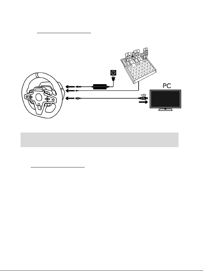
12/32
INSTALACIÓN EN PC*
* Funcionalidad de PC no avalada por Sony Interactive Entertainment Europe y Sony Interactive
Entertainment LLC.
1. Visita https://support.thrustmaster.com
Feedback para PC. Haz clic en Volantes de carreras / T248 / Controladores.
2. Enchufa el cable de alimentación y el adaptador de corriente en un enchufe eléctrico.
3. Conecta el cable USB-A (17b) a un puerto USB-A en el PC.
para descargar los controladores y el software Force
¡Ya estás preparado para jugar!
Nota:
- En el Panel de control y en los juegos, el volante de carreras se reconoce con el nombre
Thrustmaster Advanced Racer.
ACTUALIZACIÓN DEL FIRMWARE DEL VOLANTE DE CARRERAS
Visita https://support.thrustmaster.com
Haz clic en Volantes de carreras / T248 / Firmware, y sigue las instrucciones.
.
Page 78

13/32
MAPEADO PARA CONSOLAS PLAYSTATION®4 O CONSOLAS
PLAYSTATION
USO DE LOS CODIFICADORES E1 / E2 / E3 / E4
Puedes seleccionar el codificador activo empujando el interruptor selector de codificador (4) hacia
arriba. El codificador activo se muestra en la pantalla: E1, E2, E3, E4 en sucesión, y luego E1… y
así sucesivamente.
Cuando se selecciona el codificador (E1, E2, E3 o E4), las funciones asociadas son las siguientes:
- Push (P) empujando el interruptor selector de codificador (4) hacia abajo.
- + empujando el interruptor selector de codificador del lado derecho (5) hacia arriba.
- - empujando el interruptor selector de codificador del lado derecho (5) hacia abajo.
La acción correspondiente se muestra en la pantalla.
Nota:
- Los codificadores E1, E2, E3 y E4 funcionan en juegos compatibles con los codificadores
Thrustmaster (F1 2020, F1 2021, Gran Turismo Sport, Assetto Corsa® Competizione, y otros
próximos juegos).
- La pantalla muestra las funciones de información de telemetría en juegos compatibles con el SDK
(kit de desarrollo de software) de Thrustmaster. La lista de juegos compatibles está disponible
aquí: https://support.thrustmaster.com (en la sección Volantes de carreras / T248 /
Configuración de juegos). Esta lista se actualiza regularmente.
®5
Page 79
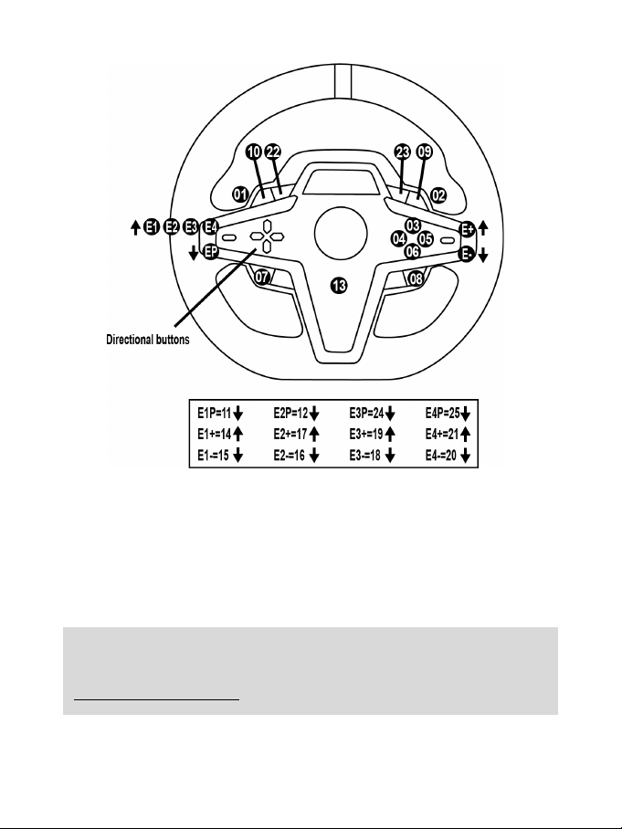
14/32
MAPEADO PARA PC
USO DE LOS CODIFICADORES E1 / E2 / E3 / E4
Puedes seleccionar el codificador activo empujando el interruptor selector de codificador (4) hacia
arriba. El codificador activo se muestra en la pantalla: E1, E2, E3, E4 en sucesión, y luego E1… y
así sucesivamente.
Cuando se selecciona el codificador (E1, E2, E3 o E4), las funciones asociadas son las siguientes:
- Push (P) empujando el interruptor selector de codificador (4) hacia abajo.
- + empujando el interruptor selector de codificador del lado derecho (5) hacia arriba.
- - empujando el interruptor selector de codificador del lado derecho (5) hacia abajo.
La acción correspondiente se muestra en la pantalla.
Nota:
- Los codificadores E1, E2, E3 y E4 funcionan en la mayoría de los juegos.
- La pantalla muestra las funciones de información de telemetría en juegos compatibles con el SDK (kit
de desarrollo de software) de Thrustmaster. La lista de juegos compatibles está disponible aquí:
https://support.thrustmaster.com (en la sección Volantes de carreras / T248 / Configuración de
juegos). Esta lista se actualiza regularmente.
Page 80

15/32
BOTÓN MODE
VISUALIZACIÓN DE INFORMACIÓN SOBRE EL VOLANTE DE CARRERAS Y CONFIGURACIÓN DEL VOLANTE
DE CARRERAS Y EL JUEGO DE PEDALES
Pulsa el botón MODE (9) para entrar en el menú MODE (MODO).
Cuando estás en este menú sólo se muestran los dos primeros segmentos.
Page 81

16/32
Usa los botones de dirección (7) en este menú de la siguiente manera:
- Selección de consola PS4™ (de
EXIT aparezca en la pantalla.
- Versión de firmware de la base
conectado al conector RJ12 (24)
FFB
PERFIL DE FFB)
ROT°
automático)
- 270°
predeterminada)
- FLOOR: posición en el suelo (de
embrague están invertidos)
TEMP
motor
- N: No
la pantalla.
Navegación Pantalla Información / Opciones
8 niveles
PS/PC
Seleccionar el
sistema: consola
3 opciones
3 pantallas
3 opciones
6 opciones
6 opciones
2 opciones
1 visualización
1 opción
PS4™, consola
PS5™ o PC
ABOUT
Información general
Seleccionar el perfil
de Force Feedback
(consulta la sección
DIAGRAMA DE
FORCE
Seleccionar el
nivel general del
efecto de fuerza
del volante
Seleccionar el
ángulo de giro
(sólo para juegos en
los que el ángulo de
giro no es
PEDAL
Seleccionar la
configuración del
juego de pedales
Temperatura del
RESET
Restablece el
volante de carreras
al modo
predeterminado.
forma predeterminada)
- Selección de consola PS5™
- Selección de sistema de PC
Nota: Para validar el sistema
elegido, pulsa el botón MODE (9).
La selección se guardará cuando
del volante de carreras
- Nombre del dispositivo conectado
al conector mini-DIN (23)
- Tipo de juego de pedales
- FFB 1
- FFB 2 (de forma predeterminada)
- FFB 3
- 360°
- 540°
- 720°
- 900°
- AUTO = automático (de forma
forma predeterminada)
- INV.: posició n suspendida
(los pedales del acelerador y del
Temperatura del motor del volante de
carreras mostrada en tiempo real
- Y: Sí
Selecciona Y, después pulsa el botón
MODE (9). El volante de carreras se
restablece cuando EXIT aparece en
Page 82

17/32
FORCE
Permite ajustar en tiempo real (= directamente en la carrera) todos los efectos de fuerza del volante
de carreras del 20 al 100%.
DIAGRAMA DE PERFIL DE FFB (FFB 1 / FFB 2 / FFB 3)
1
FFB
El efecto FFB 1 proporciona Force Feedback lineal. La fuerza que sientes es 100% proporcional a la
fuerza solicitada por el juego.
2 y FFB 3
FFB
Los efectos FFB 2 y FFB 3 potencian el Force Feedback para acentuar la fuerza que sientes en
relación con la fuerza solicitada por el juego.
Nota:
- Valida tus elecciones pulsando el botón MODE (9): EXIT (SALIR) se muestra antes de regresar a la
pantalla predeterminada.
- Los botones de dirección (7) están desactivados en los juegos y en la interfaz de la consola cuando
el botón MODE está activado.
Page 83

18/32
BOTÓN DISPLAY
CONFIGURACIÓN DE LA VISUALIZACIÓN DE LOS AJUSTES DE TELEMETRÍA
(en juegos compatibles)
Nota:
- La lista de juegos compatibles con la pantalla T-RDD (Thrustmaster Race Dash Display) está
disponible aquí: https://support.thrustmaster.com (en la sección Volantes de carreras / T248 /
Configuración de juegos). Esta lista se actualiza regularmente.
- El botón DISPLAY solo funciona en estos juegos.
Pulsa el botón DISPLAY (11) para entrar en el menú DISPLAY (VISUALIZACIÓN).
Cuando estás en este menú sólo se muestran los dos últimos segmentos.
Page 84
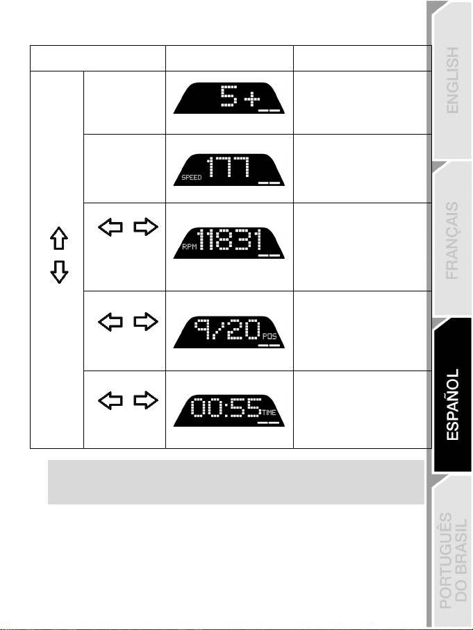
19/32
Usa los botones de dirección (7) en este menú de la siguiente manera:
Navegación Pantalla Información / Opciones
No
Cambio de marchas
SPEED
5 niveles
5 opciones para
mostrar en los
No
segmentos
Velocidad
RPM
RPM y elección de vista en los
9 segmentos
- REV >>: de izquierda a derecha
- REV <<: de derecha a izquierda
- REV ><: de afuera hacia el
centro
- REV <>: del centro hacia afuera
- REV --: sin visualización en los
segmentos
POS
- DRI: posición en la carrera
2 opciones
Posición
TIME
3 opciones
Nota:
- Valida tus elecciones pulsando el botón DISPLAY (11).
- Los botones de dirección (7) están desactivados en los juegos y en la interfaz de la consola cuando el
botón DISPLAY está activado.
Tiempo
- LAP: número de vueltas
- PBL: mejor tiempo de vuelta
personal
- C L: tiempo de vuelta actual
- L L: tiempo de la última vuelta
Page 85

20/32
VARIOS CONSEJOS Y PREGUNTAS FRECUENTES
Visita https://support.thrustmaster.com. Haz clic en Volantes de carreras / T248, y después en
Manual o PF (Preguntas frecuentes).
Page 86

21/32
JUEGO DE PEDALES T3PM
Page 87

22/32
CARACTERÍSTICAS TÉCNICAS
1 Juego de pedales
6 Anillo de amortiguación de elastómero
9 Espaciador de plástico inferior (rojo)
2 Muelle duro adicional (negro)
3 Llave Allen de 2,5 mm
4 Varilla de retención del muelle
5 Cabezal de retención superior con arandela
(blanco – Shore 70)
7 Espaciador de plástico superior (rojo)
8 Muelle blando (plateado – instalado por
defecto)
Page 88

23/32
ADVERTENCIA
NUNCA
NUNCA
NUNCA
Antes de utilizar este producto, lee detenidamente este manual y consérvalo para consultarlo
posteriormente.
Por razones de seguridad, no uses nunca los pedales con los pies descalzos
THRUSTMASTER® DECLINA TODA RESPONSABILIDAD EN CASO DE
LESIONES PRODUCTO DEL USO DE LOS PEDALES SIN CALZADO.
Advertencia – Peligro de pillarse los dedos con los pedales mientras se juega
* Mantén los pedales fuera del alcance de los niños.
* Cuando juegues, no pongas nunca los dedos en los lados de los pedales ni cerca de ellos.
* Cuando juegues, no pongas nunca los dedos sobre la base trasera de los pedales ni cerca de ella.
* Cuando juegues, no pongas nunca los dedos sobre la base delantera de los pedales ni cerca de ella.
o únicamente con calcetines en los pies.
Page 89

24/32
CALIBRACIÓN AUTOMÁTICA DE LOS PEDALES
- No conectes nunca los pedales a la base del volante de carreras (ni los desconectes de la base)
cuando esté conectada a la consola PS4™ o la consola PS5™, o durante el juego (esto podría
provocar una calibración incorrecta).
Conecta siempre los pedales antes de conectar el volante de carreras a la consola.
- Una vez que se ha realizado la calibración del volante de carreras y el juego se ha ejecutado, los
pedales se calibran automáticamente tras presionarlos unas cuantas veces.
- ¡No presiones nunca los pedales durante la fase de autocalibración del volante de carreras ni
mientras se está cargando un juego! Esto podría provocar una calibración incorrecta.
Si el volante de carreras y/o los pedales no funcionan correctamente, o si la calibración
parece incorrecta:
Apaga la consola, desconecta por completo el volante de carreras, vuelve a conectar todos los
cables (incluyendo el cable de fuente de alimentación y los pedales) y reinicia la consola y el juego.
IMPORTANTE
Page 90

25/32
FIJACIÓN DE LOS PEDALES A UN SOPORTE O UNA CABINA
El juego de pedales se puede fijar a diversos soportes compatibles (vendidos por separado),
usando los cinco agujeros con rosca M6 situados bajo la base. Para hacerlo, atornilla al menos dos
tornillos M6 (no incluidos) a través del estante del soporte y en los agujeros roscados en la cara
inferior de la base de los pedales.
Importante: la longitud de los tornillos M6 no debe superar el grosor de su soporte en más
de 12 mm, para no correr el riesgo de dañar los componentes internos de los pedales.
Los diagramas de configuración de los pedales para cabinas y otros soportes están
disponibles en https://support.thrustmaster.com
después en Template - Cockpit setup (Plantilla - Configuración de la cabina).
: haz clic en Volantes de carreras / T3PM, y
Page 91

26/32
AJUSTE DE LOS PEDALES
Cada uno de los tres pedales incluye:
- Un brazo del pedal (10) con dos perforaciones.
- Un soporte de plástico del cabezal (11) (situado entre el cabezal y el brazo) con cuatro
perforaciones.
- Un cabezal metálico (12) con varias perforaciones (nueve para el acelerador, seis para el freno y
seis para el embrague).
ATENCIÓN: Para evitar problemas de calibración, asegúrate de desconectar siempre el cable
USB del volante de la consola o del PC antes de hacer ajustes en los pedales.
Ajuste de la ALTURA del pedal de gas
- Con la llave Allen de 2,5 mm incluida (3), desatornilla los dos tornillos que sujetan el cabezal
metálico (12) y su soporte (11) en su sitio.
- Selecciona la posición de altura que prefieras y, después, sustituye y vuelve a apretar los tornillos
de forma que el cabezal metálico (12) y su soporte (11) queden sujetos firmemente en su sitio.
Posición baja Posición alta (predeterminada)
Page 92

27/32
Ajuste del ESPACIADO de los tres pedales
Posición izquierda
Posición centrada (predet.)
Posición derecha
- Con la llave Allen de 2,5 mm incluida (3), desatornilla los dos tornillos que sujetan el cabezal
metálico (12) y su soporte (11) en su sitio.
- Selecciona la posición de altura que prefieras (a la izquierda, centrada o a la derecha) y, a
continuación, sustituye y vuelve a apretar los tornillos de forma que el cabezal metálico (12) y su
soporte (11) queden sujetos firmemente en su sitio.
Ejemplos que ilustran el pedal del freno:
Ajuste de la INCLINACIÓN de los pedales
- Con la llave Allen de 2,5 mm incluida (3), desatornilla los dos tornillos que sujetan el cabezal
metálico (12) y su soporte (11) en su sitio.
- Gira el soporte de plástico del cabezal (11) 180° y, después, sustituye y vuelve a apretar los
tornillos de forma que el cabezal metálico (12) y su soporte (11) queden sujetos firmemente.
Número de posiciones de espaciado posibles por pedal:
- Tres para el pedal de gas
- Tres para el pedal del freno
- Tres para el pedal del embrague
Ejemplos que ilustran el pedal de gas:
Posición menos inclinada (predeterminada) Posición más inclinada
Número de posiciones de inclinación posibles por pedal:
- Dos para el pedal de gas
- Dos para el pedal del freno
- Dos para el pedal del embrague
Page 93
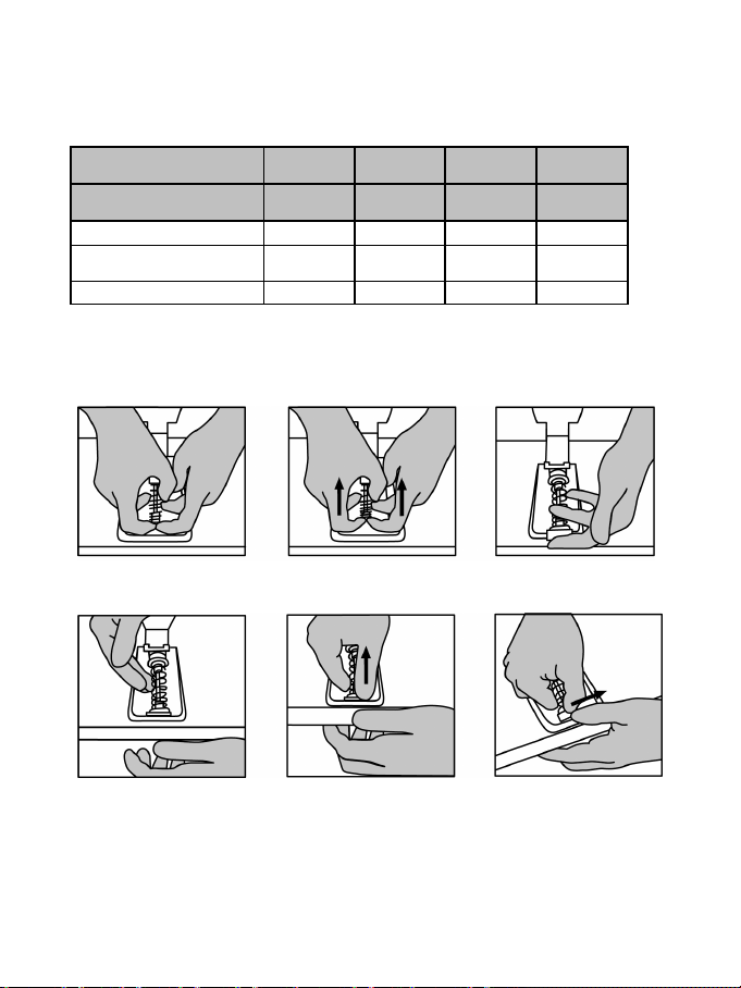
28/32
JUEGO DE MUELLES DEL FRENO INCLUIDOS
Media
(predet.)
Soporte de
pedales
Muelle plateado blando (8)
x
x
Anillo de amortiguación de
elastómero blanco (6)
x x
Muelle negro duro (2)
x x
4 configuraciones y ajustes posibles para la fuerza de presión del freno
Este mod te permite experimentar una resistencia y sensación diferentes al frenar.
Puedes optar por instalarlo o no, según tus preferencias.
Resistencia del freno Suave
Dura Muy dura
Uso recomendado Escritorio Escritorio
1. Tira con fuerza del espaciador de plástico inferior (9) para comprimir el muelle y retira la varilla
de retención del muelle (4) de su ubicación.
Método 1:
Método 2:
Cabina
Page 94
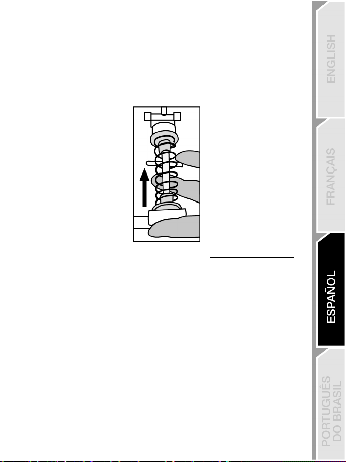
29/32
2. Vuelve a colocar los diferentes elementos en la varilla de retención del muelle (4).
Comienza con el espaciador de plástico inferior (9), el muelle que elijas (2) u (8), y luego el
espaciador de plástico superior (7).
3. Después de la configuración seleccionada, instala el anillo de amortiguación de elastómero (6).
4. Ajusta el cabezal de retención superior con la arandela (5) y colócalo en su ubicación.
5. Comprime fuertemente el muelle para colocar la varilla de retención del muelle (4) en su
ubicación.
Un video que muestra cómo cambiar el muelle está disponible en https://support.thrustmaster.com
haz clic en Volantes de carreras / T3PM.
:
Page 95

30/32
INFORMACIÓN DE GARANTÍA AL CONSUMIDOR
En todo el mundo, Guillemot Corporation S.A., cuyo domicilio legal se encuentra en Place du Granier, B.P. 97143,
35571 Chantepie, Francia (en lo sucesivo “Guillemot”) garantiza al consumidor que este producto de Thrustmaster
estará libre de defectos de materiales y mano de obra, durante un período de garantía que corresponde al límite de
tiempo para interponer una acción legal referida a la conformidad en relación con este producto. En los países de la
Unión Europea, esto corresponde a un período de dos (2) años a partir de la entrega del producto de Thrustmaster. En
otros países, el período de garantía corresponde al límite de tiempo para interponer una acción legal referida a la
conformidad en relación con este producto de Thrustmaster según las leyes aplicables del país en el que el consumidor
estuviese domiciliado en la fecha de compra del producto de Thrustmaster (si no existiese una acción similar en el país
correspondiente, entonces el período de garantía será de un (1) año a partir de la fecha de compra original del producto
de Thrustmaster).
Si el producto resultase defectuoso durante el período de garantía, hay que ponerse en contacto inmediatamente con el
Soporte Técnico, que indicará el procedimiento a seguir. Si se confirma el defecto, el producto debe devolverse a su
lugar de compra (o a cualquier otra ubicación indicada por el Soporte Técnico).
Dentro del contexto de esta garantía, el producto defectuoso del consumidor será sustituido o restaurado su
funcionamiento correcto. Si, durante el período de garantía, el producto de Thrustmaster fuese sometido a dicho
reacondicionamiento, cualquier período de cómo mínimo siete (7) días durante el que el producto no se pueda usar se
añadirá al período de garantía restante (este período va desde la fecha de petición de intervención del consumidor o
desde la fecha en la que el producto se entrega para el reacondicionamiento, si la fecha en la que el producto se
entrega para el reacondicionamiento fuese posterior a la fecha de la petición de intervención). Si la ley aplicable lo
permite, toda la responsabilidad de Guillemot y sus filiales (incluso por daños resultantes) se limita a la restauración del
funcionamiento correcto o la sustitución del producto de Thrustmaster. Si la ley aplicable lo permite, Guillemot renuncia
a todas las garantías de comerciabilidad o adecuación para un propósito determinado.
Esta garantía no se aplicará: (1) si el producto ha sido modificado, abierto, alterado o ha sufrido daños como resultado
de un uso inapropiado o abuso, negligencia, accidente, desgaste normal, o cualquier otra causa no relacionada con un
defecto de materiales o fabricación (incluyendo, pero no de forma exclusiva, la combinación del producto de
Thrustmaster con cualquier elemento no adecuado, incluyendo en particular fuentes de alimentación, baterías
recargables, cargadores o cualquier otro elemento no suministrado por Guillemot para este producto); (2) si el producto
se ha empleado para otro uso distinto del doméstico, incluyendo fines profesionales o comerciales (salones de juego,
entrenamiento, competiciones, por ejemplo); (3) en caso de incumplimiento de las instrucciones proporcionadas por el
Soporte Técnico; (4) a software, es decir software sujeto a una garantía específica; (5) a consumibles (elementos que
se tienen que reemplazar a lo largo de la vida del producto: por ejemplo, baterías desechables o almohadillas para
auriculares de audio); (6) a accesorios (por ejemplo, cables, cajas, bolsas, bolsos o muñequeras); (7) si el producto se
ha vendido en una subasta pública.
Esta garantía no es transferible.
Los derechos legales del consumidor en relación con las leyes aplicables a la venta de productos de consumo de su
país no se ven afectados por esta garantía.
Page 96

31/32
SOPORTE TÉCNICO
Provisiones de garantía adicionales
Durante el período de garantía, Guillemot no proporcionará, en principio, ninguna pieza de repuesto, ya que el Soporte
Técnico es el único autorizado para abrir y/o reacondicionar los productos de Thrustmaster (con la excepción de los
procedimientos de reacondicionamiento que el Soporte técnico puede solicitar que lleve a cabo el consumidor,
mediante instrucciones por escrito – por ejemplo, debido a la simplicidad y la falta de confidencialidad del proceso de
reacondicionamiento – y suministrando al consumidor las piezas de repuesto necesarias, si hiciese falta).
Debido a sus ciclos de innovación y para proteger su know-how y secretos comerciales, Guillemot no proporcionará, en
principio, ninguna pieza de repuesto ni instrucciones de reacondicionamiento para los productos de Thrustmaster cuyo
período de garantía haya vencido.
En los Estados Unidos de América y en Canadá, esta garantía está limitada al mecanismo interno del producto y al
alojamiento externo. En ningún caso, Guillemot ni sus filiales serán responsables ante terceros por daños resultantes o
fortuitos resultado del incumplimiento de cualquier garantía expresa o implícita. En algunos estados o provincias no se
permite la limitación de la duración de una garantía implícita ni la exclusión o limitación de responsabilidad por daños
resultantes o fortuitos, por lo que las limitaciones o exclusiones anteriores pueden no ser aplicables. Esta garantía
ofrece derechos legales específicos al consumidor, que también puede tener otros derechos que pueden variar de un
estado a otro o de una provincia a otra.
Responsabilidad
Si la ley aplicable lo permite, Guillemot Corporation S.A. (en lo sucesivo “Guillemot”) y sus filiales renuncian a toda
responsabilidad por los daños causados por uno o más de los siguientes motivos: (1) el producto ha sido modificado,
abierto o alterado; (2) incumplimiento de las instrucciones de montaje; (3) uso inapropiado o abuso, negligencia,
accidente (un impacto, por ejemplo); (4) desgaste normal; (5) el producto se ha empleado para otro uso distinto del
doméstico, incluyendo fines profesionales o comerciales (salones de juego, entrenamiento, competiciones, por
ejemplo). Si la ley aplicable lo permite, Guillemot y sus filiales renuncian a toda responsabilidad por los daños no
relacionados con defectos de materiales o fabricación en relación con el producto (incluyendo, pero no de forma
exclusiva, los daños causados de forma directa o indirecta por cualquier software, o por combinar el producto de
Thrustmaster con cualquier elemento no adecuado, incluyendo en particular fuentes de alimentación, baterías
recargables, cargadores o cualquier otro elemento no suministrado por Guillemot para este producto).
DECLARACIÓN DE CONFORMIDAD
NOTICIA DE CONFORMIDAD EN USA: este dispositivo cumple con los límites para dispositivos de computación de
Clase B de acuerdo con la Parte 15 de las reglas FCC.
https://support.thrustmaster.com
Page 97

32/32
COPYRIGHT
*
*
*
© 2021 Guillemot Corporation S.A. Todos los derechos reservados. Thrustmaster® es una marca comercial
registrada de Guillemot Corporation S.A. Fabricado y distribuido por Guillemot Corpora tion S.A. Todas las dem ás
marcas comerciales y nombres de marca se reconocen por la presente y son propiedad de sus respectivos
dueños. Los contenidos, diseños y especificaciones están sujetos a cambios sin previo aviso y pueden variar de
un país a otro. Fotos e ilustraciones no vinculantes. Diseñado en Norteamérica y Europa, fabricado en China.
Para usar exclusivamente con consolas PlayStation
"1", "PlaySt ation", "PS5", "PS4" y “PlayStation Shapes Logo” son marcas comerciales registradas o marcas
comerciales de Sony Interactive Ent ertainment Inc. Todos lo s derechos res ervados. Todas las demás marcas
comerciales son propiedad de sus respectivos dueños. Fabricado y distribuido con licencia de Sony Interactive
Entertainment LLC.
®5 y consolas PlayStation®4.
RECOMENDACIÓN DE PROTECCIÓN AMBIENTAL
En la Unión Europea, Reino Unido y Turquía: Al terminar su vida útil, este
producto no debe tirarse en un contenedor de basuras estándar, sino que debe
dejarse en un punto de recogida de desechos eléctricos y equipamiento
electrónico para ser reciclado.
Esto viene confirmado por el símbolo que se encuentra en el producto, manual del
usuario o embalaje.
Dependiendo de sus características, los materiales pueden reciclarse. Mediante el
reciclaje y otras formas de procesamiento de los desechos eléctricos y el
equipamiento electrónico puedes contribuir de forma significativa a ayudar a
proteger el medio ambiente.
Contacta con las autoridades locales para más información sobre el punto de recogida más cercano.
Para los demás países: cumpla las leyes locales sobre reciclaje de equipos eléctricos y electrónicos.
Esta información debe conservarse. Los colores y motivos decorativos pueden variar.
Los adhesivos y los cierres de plástico se deben quitar del producto antes de utilizarlo.
www.thrustmaster.com
*Aplicable únicamente a la UE, Reino Unido y Turquía
Page 98

1/32
®
Para consoles PlayStation
5 e consoles PlayStation®4
Manual do Usuário
Page 99
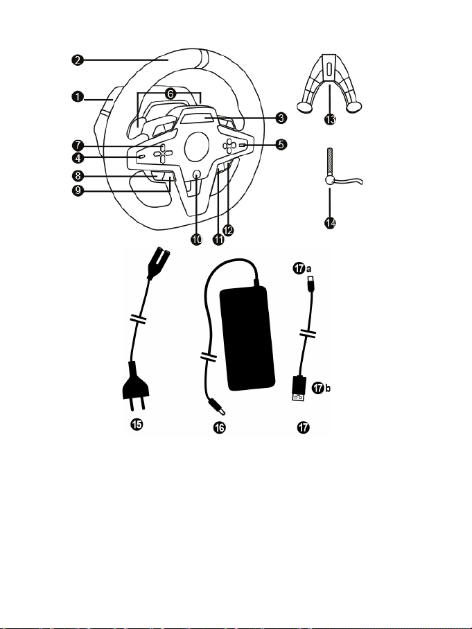
2/32
CARACTERÍSTICAS TÉCNICAS
1 Base do T248
9 Botão MODE
10 Botão PS
2 Volante
3 Tela T-RDD (Thrustmaster Race Dash Display)
4 Seletor de codificador e função de pressionar
do codificador
5 Seletor + e - do codificador
6 2 borboletas magnéticas de câmbio (para cima
e para baixo)
7 Botões direcionais
8 Botão SHARE em consoles PS4™
Botão CREATE em consoles PS5™
11 Botão DISPLAY
12 Botão OPTIONS em consoles PS4™ e
consoles PS5™
13 Sistema de fixação
14 Parafuso de metal para fixação
15 Cabo de alimentação (UE/EUA ou Reino
Unido...)
16 Adaptador de alimentação
17 Cabo USB-C (17a) – USB-A (17b)
Page 100

3/32
ca para fixação em um
18 Orifício com rosca (para sistema e parafuso
de fixação)
19 Orifícios com ros
cockpit de corrida (não incluído)
20 Suporte de cabo com velcro de fixação
21 Conector do adaptador de alimentação
22 Conector USB-C do volante
23 Conector Mini-DIN para câmbio, freio de
mão ou hub Thrustmaster (todos vendidos
separadamente)
24 Conector RJ12 para conjunto de pedais
 Loading...