

Page 1

November 2009 Anuj Aggarwal
Document Version 01.11.00.XX
EDMA3 Driver
User Guide
Page 2

Read This First
ii
IMPORTANT NOTICE
Texas Instruments Incorporated and its subsidiaries (TI) reserve the right to make corrections,
modifications, enhancements, improvements, and other changes to its products and services at any
time and to discontinue any product or service without notice. Customers should obtain the latest
relevant information before placing orders and should verify that such information is current and
complete.
TI assumes no liability for applications assistance or customer product design. Customers are
responsible for their products and applications using TI components. To minimize the risks
associated with customer products and applications, customers should provide adequate design and
operating safeguards.
TI does not warrant or represent that any licen se, either express or implied, is granted under any TI
patent right, copyright, mask work right, or other TI intellectual property right relating to any
combination, machine, or process in which TI products or services are used. Information published
by TI regarding third-party products or servi ces does not constitute a license from TI to use such
products or services or a warranty or endorsement thereof. Use of such information may require a
license from a third par ty under the patents or other intellectual property of the third party, or a
license from TI under the patents or other intellectual property of TI
Mailing Address:
Texas Instruments
Post Office Box 655303, Dallas, Texas 75265
Copyright © 2009, Texas Instruments Incorporated
LICENSE
This work is licensed under the Creative Commons Attribution-Share Alike 3.0 United
States License. To view a copy of this license, visit
http://creativecommons.org/licenses/by-sa/3.0/us/
or send a letter to Creative Commons,
171 Second Street, Suite 300, San Francisco, California, 94105, USA.
Page 3

iii
Preface
Read This First
About This Manual
This User’s Manual serves as a software programmer’s handbook for
working with the EDMA3 Driver Version 01.11.00.XX. This manual
provides necessary information regarding how to effectively install, build
and use
EDMA3 Driver in user systems and applications.
This manual provides details regarding how the
EDMA3 Driver is
Architected, its composition, its functionality, the requirements it places on
the hardware and software environment where it can be deployed, how to
customize/configure it to specific requirements, how to leverage the
supported run-time interfaces in user’s own application etc.,
This manual also provides supplementary information regarding steps to
be followed for proper installation/ un-installation of the EDMA3 Driver.
Also included are appendix sections on related Glossary, Web sites and
Pointers for gathering further information on the EDMA3 Driver.
Page 4

Read This First
iv
Terms and Abbreviations
Add any longer explanations for terms before the table.
Add any abbreviations and short explanations to the table.
Term/Abbreviation Description
EDMA Enhanced Direct Memory Access
EDMA3 Controller Consists of the EDMA3 channel controller (EDMA3CC) and
EDMA3 transfer memory access controller(s) (EDMA3TC). Is
referred to as EDMA3 in this document.
DMA Direct Memory Access
QDMA Quick DMA
TCC Transfer Completion Code (basically Interrupt Channel)
ISR Interrupt Service Routine
CC Channel Controller
TC Transfer Controller
RM Resource Manager
TR Transfer Request.
A command for data movement that is issued from the
EDMA3CC to the EDMA3TC. A TR includes source and
destination addresses, counts, indexes, options, etc.
Page 5

Read This First
v
Notations
Explain any special notations or typefaces used (such as for API
guides, special typefaces for functions, variables, etc.)
Information about Cautions and Warnings
This book may contain cautions and warnings.
CAUTION
WARNING
The information in a caution or a warning is provided for your
protection. Please read each caution and warning carefully.
This is an example of a caution statement.
A caution statement describes a situation that could potentially
damage your software or equipment.
This is an example of a warning statement.
A warning statement describes a situation that could potentially
cause harm to you
.
Page 6

Read This First
vi
Related Documentation
EDMA3 Channel Controller (TPCC), version 3.0.2
EDMA3 Transfer Controller (TPTC), version 3.0.1
Trademarks
The TI logo design is a trademark of Texas Instruments
Incorporated. All other brand and product names may be
trademarks of their respective companies.
Page 7

Read This First
vii
Revision History
Date Author Revision History Version
November 2,
2009
Anuj
Aggarwal
a) Added CCSv4 / BIOS5 support and linux
installer in LLD.
b) IRs SDOCM00061179 (Device 6748 isn't
listed in package.xs file of
ti.sdo.fc.edma3.rm) & SDOCM00061809
(Exception occurs when edma3deinit()
API called) fixed.
See release notes for more information.
01.11.00.XX
July 9, 2009 Anuj
Aggarwal
a) ECN# TIDSP00012004 (Migration to new
BSD license) and TIDSP00011985
(Addition of new API
EDMA3_DRV_disableLogicalChannel API
in EDMA3 Driver) implemented.
b) IRs# SDOCM00058021,
SDOCM00058057, SDOCM00058147 and
SDOCM00058401 fixed.
See release notes for more information.
01.10.00.01
May 11, 2009 Anuj
Aggarwal
a) Add support for new platforms: C6748,
OMAPL138, DRA44x and DRX45x.
01.07.00.01
November 4,
2008
Anuj
Aggarwal
a) Added support for new platforms.
b) IR SDOCM00049778 is fixed.
See release notes for more information.
01.06.00.01
March 20,
2008
Anuj
Aggarwal
a) Added support for new platforms.
b) MRs DPSP00010071, DPSP00010187,
DPSP00010479 and DPSP00010480 are
fixed.
See release notes for more information.
1.05.00.01
January 28,
2008
Anuj
Aggarwal
a) Header files modified to have extern "C"
declarations.
b) Implemented ECNs DPSP00009815 &
DPSP00010035.
1.04.00.01
January 9,
2008
Anuj
Aggarwal
a) MR# DPSP00009788 has been fixed in
this release. See Release Notes for more
information.
1.03.01.01
October 21,
2007
Anuj
Aggarwal
a) C6452 support has been added in this
release. Now C6452 applications can also
be built in the RTSC environment.
b) All the CCS PJT files now come under two
flavors: one for the RTSC environment
and the other for the non-RTSC
environment.
c) IOCTL interface has been added in the
EDMA3 Driver.
d) MRs DPSP00009099, DPSP00009190 and
DPSP00009213 Fixed. See Release Notes
for more information.
1.03.00.01
Page 8

Read This First
viii
September 28,
2007
Anuj
Aggarwal
a) Added support for DM6467 platform.
b) MRs DPSP00009060, DPSP00009063,
DPSP00009093 and DPSP00009100
Fixed. See Release Notes for more
information.
1.02.00.01
September 14,
2007
Anuj
Aggarwal
a) Moved the platform specific configuration
to the Resource Manager.
b) Modified the chaining API.
c) Divided the sample app into sample
initialization library and the standalone
sample application.
1.01.00.01
July 11, 2007 Anuj
Aggarwal
a) Modified the DSP/BIOS version number.
b) Modified the Driver directory structure as
per RTSC standard.
1.00.00.03
June 18, 2007 Anuj
Aggarwal
a) Made the EDMA3 package RTSC
compliant.
1.00.00.02
May 14, 2007 Anuj
Aggarwal
a) MR# DPSP00007858 (Issue in EDMA3
DRV causes false missed events) Fixed.
1.0.0.1
May 9, 2007 Anuj
Aggarwal
a) MR# DPSP00007800 (Result of resource
allocation is over-written by the semaphore
release result in EDMA3 Resource Manager)
Fixed.
b) MR# DPSP00007803 (Exit from
EDMA3_RM_allocContiguousResource () in
case of error is incorrect) Fixed.
1.0.0
Apr 23, 2007 Anuj
Aggarwal
a) New APIs to support POLL mode provided.
b) API to set CC Register provided.
c) Sample application made generic and
more test cases added.
0.3.2
Mar 23, 2007 Anuj
Aggarwal
a) DMA/QDMA channel event missed issue
fixed.
0.3.1
Mar 6, 2007 Anuj
Aggarwal
a) Renamed EDMA3_DVR to EDMA3_DRV.
b) IPR bit clearing in RM ISR issue fixed.
c) Sample application made generic.
0.3.0
Jan 16, 2007 Anuj
Aggarwal
Critical section handling code modification.
Uses semaphore and interrupts disabling
mechanism for resources sharing.
0.2.2
Nov 14, 2006 Anuj
Aggarwal
Made EDMA3 Driver OS Independent. Also,
more run time configuration is possible now.
0.2.1
Page 9

Contents
ix
Contents
Read This First............................................................................................................ iii
About This Manual..........................................................................................................iii
This manual also provides supplementary information regarding steps to be
followed for proper installation/ un-installation of the EDMA3 Driver. Also
included are appendix sections on related Glossary, Web sites and Pointers for
gathering further information on the EDMA3 Driver. Terms and Abbreviations
.iii
Terms and Abbreviations ............................................................................................. iv
Notations v
Information about Cautions and Warnings ................................................................ v
Related Documentation................................................................................................ vi
Trademarks vi
Revision History.............................................................................................................vii
Contents........................................................................................................................ ix
Tables............................................................................................................................. xi
EDMA3 Driver Introduction...............................................................................0-1-1
1.1 Overview ...........................................................................................0-1-2
1.1.1 System Partitioning .................................................................................0-1-2
1.1.2 Supported Services .................................................................................0-1-6
Installation Guide.................................................................................................1-2-1
2.1 Component Folder ...........................................................................1-2-2
2.2 Development Tools Environment(s) .............................................1-2-4
2.2.1 Development Tools..................................................................................1-2-4
2.3 Installation guide .............................................................................1-2-5
2.3.1 Installation and Usage Procedure..........................................................1-2-5
2.3.2 Un-installation ..........................................................................................1-2-5
2.4 Integration Guide.............................................................................1-2-6
2.4.1 Building EDMA3 Libraries........................................................................1-2-6
2.4.2 Building the EDMA3 Driver Stand-alone Applications.........................1-2-6
2.4.3 Building the DAT Example......................................................................1-2-7
2.4.4 Build Options ............................................................................................1-2-8
Run-Time Interfaces/Integration Guide..................................................... 2-A-1
3.1 Symbolic Constants and Enumerated Data types ..................... 2-A-2
3.2 Data Structures............................................................................. 2-A-13
3.2.1 EDMA3_DRV_GblConfigParams .......................................................... 2-A-13
3.2.2 EDMA3_DRV_InstanceInitConfig ........................................................ 2-A-16
3.2.3 EDMA3_DRV_InitConfig....................................................................... 2-A-18
3.2.4 EDMA3_DRV_MiscParam...................................................................... 2-A-19
3.2.5 EDMA3_DRV_ChainOptions................................................................. 2-A-20
3.2.6 EDMA3_DRV_PaRAMRegs.................................................................... 2-A-21
3.2.7 EDMA3_DRV_EvtQuePriority............................................................... 2-A-23
3.3 API Specification ........................................................................... 2-A-24
3.3.1 Creation.................................................................................................. 2-A-25
3.3.2 Configuration......................................................................................... 2-A-27
3.3.3 Control.................................................................................................... 2-A-29
3.3.4 Termination ........................................................................................... 2-A-68
3.4 EDMA3 Driver Initialization ......................................................... 2-A-71
Page 10

Contents
x
3.5 API Flow Diagram ......................................................................... 2-A-72
3.5.1 EDMA3 Driver Creation ........................................................................ 2-A-73
3.5.2 EDMA3 Open.......................................................................................... 2-A-73
3.5.3 EDMA3 Request Channel (DMA / QDMA Channel) ........................... 2-A-74
3.5.4 EDMA3 Request Channel (LINK Channel) ......................................... 2-A-75
3.5.5 EDMA3 Close ......................................................................................... 2-A-76
3.5.6 EDMA3 Delete........................................................................................ 2-A-77
3.6 API Usage Example ...................................................................... 2-A-78
EDMA3 Driver Porting ...................................................................................... 3-A-84
3.7 Getting Started.............................................................................. 3-A-85
3.8 Step-by-Step procedure for porting .......................................... 3-A-87
3.8.1 edma3_<PLATFORM_NAME>_cfg.c:.................................................. 3-A-87
3.8.2 edma3_rm_bios_<PLATFORM_NAME>_lib.pjt................................. 3-A-88
3.8.3 OS-dependent (sample) Implementation ......................................... 3-A-89
Page 11

Tables
xi
Tables
Table 1: Development Tools/components...................................................1-2-4
Table 2: Build Options......................................................................................... 1-2-8
Table 3: Symbolic Constants and Enumerated Data types Table for
common header file edma3_common.h............................................... 2-A-2
Table 4: Symbolic Constants and Enumerated Data types Table for
EDMA3 Driver header file edma3_drv.h
............................................... 2-A-4
Page 12

Page 13

1-1
Chapter 1
EDMA3 Driver Introduction
This chapter introduces the EDMA3 Driver to the user by providing a brief
overview of the purpose and construction of the
EDMA3 Driver along with
hardware and software environment specifics in the context of EDMA3
Driver
Deployment.
Page 14

EDMA3 Driver Introduction
1-2
1.1 Overview
This section describes the functional scope of the EDMA3 Driver and its
feature set.
A brief definition of the component is provided at this point – its main
characteristics and purpose.
1.1.1 System Partitioning
EDMA3 peripheral supports data transfers between two memory mapped
devices. It supports EDMA as well as QDMA channels for data transfer.
This peripheral IP is being re-used in different SoCs with only a few
configuration changes like number of DMA and QDMA channels supported,
number of PARAM sets available, number of event queues and transfer
controllers etc.
The EDMA3 peripheral is used by other peripherals for their DMA needs
thus the EDMA3 Driver needs to cater to the requirements of device
drivers of these peripherals as well as other application software that may
need to use the 3
rd
party DMA services.
The
EDMA3 Driver provides functionality that allows device drivers and
applications for submitting and synchronizing with EDMA3 based DMA
transfers. In order to simplify the usage, this component internally uses
the services of the
EDMA3 Resource Manager and provides one
consistent interface for applications or device drivers.
The
EDMA3 Resource Manager comprises of the following two parts:
Physical Driver: This component is responsible for the management
of several resources within the EDMA3 peripheral like DMA and QDMA
channels, TCC codes, PARAM entry, all global EDMA3 registers, queues
etc.
Interrupt Manager: This module provides the different interrupt
handlers (ISRs) for various EDMA3 interrupts like transfer completion
interrupt, CC error interrupt and TC error interrupt. Since interrupts
could be associated with TCC codes in EDMA3, this module also
provides the functionality of accepting application registration callbacks
for TCC codes and calls the callback functions upon receipt of the given
interrupt (TCC).
Moreover, these ISRs are NOT registered with the underlying OS, since
Resource Manager is an OS-agnostic module. The user application has
to do the registration / un-registration of ISRs by itself.
Page 15
EDMA3 Driver Introduction
I-1-3
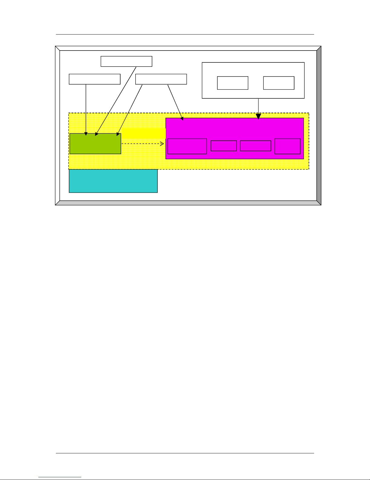
Figure 1: EDMA3 Related Software Product and Packages Structure
Dependency
EDMA3 Resource Manager
PaRAMs
DMA/QDMA
Channels
TCCs
EDMA3
ISRs
EDMA3 Driver
Internally calls
EDMA3 Product
PSP Drivers
CSL/DAT
Framework Components
DMAN
ACPY
Applications
Page 16
EDMA3 Driver Introduction
1-4
Typically, each master (ARM, DSP etc.) within the SoC shall open an instance of
EDMA3 Driver, which internally will open a Resource Manager Instance. Resources
could be allocated statically or dynamically to the EDMA3 Driver Instance. This
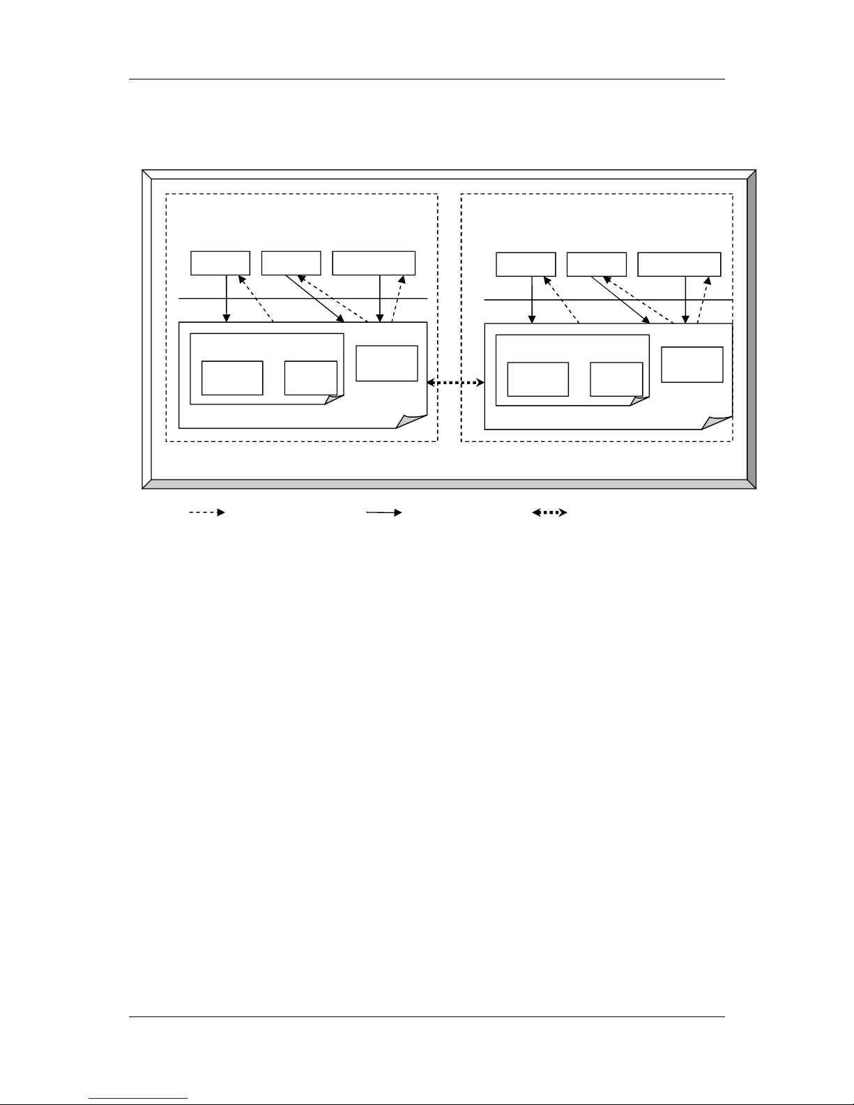
Figure 2: EDMA3 Related Software Product and Packages Structure
EDMA3 Driver Instance should be used by the users (device drivers or
applications) to call all other EDMA3 Driver APIs. This instance will use the
appropriate shadow region registers (specific to its master) to program EDMA3
hardware. Please note that the shadow region registers are master specific and
there is only and only one set of shadow region registers for each master. If a
master tries to program EDMA3 using other sets of shadow region registers (tied
to other masters in the system), it could result in unexpected behavior with the
possible loss of EDMA3 interrupts and EDMA3 resources’ conflict. So it should be
avoided in normal circumstances.
EDMA3 Driver doesn’t allow multiple instances for a single master on the
respective shadow region. It permits only one instance for each master which will
be tied to its specific shadow region. This is done to prevent any potential
problem which could arise due to EDMA3 resources’ conflict among these different
instances.
However, it is possible to have multiple EDMA3 Driver Instances, running on the
same processor. These different EDMA3 Driver instances would be tied to
different masters (and hence different shadow regions) to cater their specific
requests. The EDMA3 resources should be carefully allocated among all those
instances to avoid any possible conflict.
All software entities intending to use the services of the EDMA3 peripheral on the
given processor shall use the services of the EDMA3 Product (Resource manager
OR EDMA3 Driver) as desired.
Callback Notification Service Call Link between EDMA3 instances
SoC
Processor 1 (e.g
.
ARM)
Driver 1... NApp NApp 1
EDMA3
Driver
EDMA3 Product
EDMA3 Res Mgr
Phy Res
Mgr
Int
Mgr
Processor
2
(e.g.DSP
)
Driver 1.. NApp NApp 1
EDMA3
Driver
EDMA3 Product
EDMA3 Res Mgr
Phy Res
Mgr
Int
Mgr
Page 17

EDMA3 Driver Introduction
I-1-5
Page 18

EDMA3 Driver Introduction
1-6
1.1.2 Supported Services
Following are the services provided by the EDMA3 Driver:
1.1.2.1
Request and Free DMA channel: It provides an interface that applications or
device drivers can use to request and free DMA channels. Channels in EDMA3
module are categorized as:
DMA Channel (mapped to a hardware sync event),
DMA Channel (NOT mapped to a hardware sync event),
QDMA Channel, and
Link Channel (a PARAM Set in EDMA3).
1.1.2.2 Programs DMA channel: It provides an interface that applications or device
drivers can use to program a DMA transaction. This typically involves setting the
DMA source and destination parameters.
Following types of transactions are supported:
• Event triggered (peripheral driven transfers),
• Chain triggered (issuing a chain of transfers initiated by single
event),
• Manual triggered (CPU generated sync-event), and
• QDMA transfer (triggered on a write to the QDMA Trigger word).
Page 19

EDMA3 Driver Introduction
I-1-7
1.1.2.3 Start and Synchronize with DMA transfers: It provides an interface that
applications or device drivers can use to start and synchronize with a DMA
transaction.
1.1.2.4 Provides DMA transaction completion callback to applications: It
provides an interface that applications or device drivers can use to register a
transaction completion (final or intermediate) callback or error interrupt
callback. EDMA3 driver calls this application or device driver specifc callback
routine, with the appropriate status message.
1.1.2.5 Supports Linking and chaining feature: EDMA3 peripheral provides linking
and chaining capabilities. EDMA driver provides an interface that applications or
device drivers can use to use this functionality.
1.1.2.6 Supports multiple instances of EDMA driver on a single processor: It
supports multiple instances of itself, running on the same processor, but tied to
different masters (and hence different shadow regions). These different
instances will run on the same processor but manage same/different set of
EDMA3 resources and are tied to different shadow regions. Please note that
EDMA3 Driver doesn’t allow multiple instances for a single master on the
respective shadow region.
1.1.2.7 Read/Write a specific CC register: It also provides an interface which
enables users to read/write any EDMA3 Channel Controller register. These APIs
are for advanced users and could be used for debugging purposes.
1.1.2.8 Support for Polled Mode DMA Transfers: It provides an interface which
enables the application or device driver to use it in an interrupt-less (and further
in an OS-less) environment. In this scenario, the application does not register
the callback function with the resource manager and itself polls the EDMA3
hardware for the completion interrupt, using the specific APIs.
1.1.2.9 Non-RTSC Environment Support: EDMA3 Driver module should gets built in
non-RTSC environment also. All the CCS PJT files should come for non-RTSC
environment too.
1.1.2.10 IOCTL interface support: EDMA3 Driver shall provide an IOCTL
interface for toggling the option whether PaRAM Sets should be cleared during
allocation or not. This interface could also be extended in future for other misc
requirements.
Page 20

Page 21

2-1
Chapter 2
Installation Guide
This chapter discusses the EDMA3 Driver installation, how and what
software and hardware components to be availed in order to complete a
successful installation of
EDMA3 Driver.
Page 22

Installation Guide
2-2
2.1 Component Folder
Upon installing the EDMA3 Driver, the following directory
structure is found in the main directory.
Figure 3: EDMA3 Driver Directory Structure
The sections below describe the folder contents:
edma3_lld_<<version_number>>
Top level installation directory. Contains the source code, examples
and the documents.
docs
Contains release notes for EDMA3 Driver and Resource Manager.
examples
Contains the stand-alone applications for EDMA3 Driver (for all the
supported platforms) and the DAT example.
Page 23

Installation Guide
I-2-3
packages
All components (Driver, Resource Manager, sample OS-abstraction layers
etc) fall under packages/ti/sdo/edma3 directory, under their individual
directories. For e.g., EDMA3 Driver lies under packages/ti/sdo/edma3/drv
folder, sample initialization library for EDMA3 Driver lies under
packages/ti/sdo/edma3/drv/sample folder etc.
a)
drv -> Top level folder for the EDMA3 Driver.
b)
drv\build -> Build environment related files (PJT, TCF etc) for all
the supported platforms.
o drv\build\ccs3: Build files for CCSv3
o drv\build\ccs4: Build files for CCSv4
o drv\build\eBinder: Build files for eBinder
c)
drv\docs -> User guide, datasheet etc.
d)
drv\lib -> EDMA3 Driver libraries for all the supported platforms.
e)
drv\sample -> Sample code for how to use the EDMA3 Driver,
along-with the pre-built libraries for the same.
o drv\sample\build: Build files for CCSv3/CCSv4/eBinder
o drv\sample\lib: Pre-built libraries for EDMA3 driver
sample initialization code
o drv\sample\src: Source code for EDMA3 driver sample
initialization
f)
drv\src -> Source files for EDMA3 Driver.
Just to clarify, the
sample folder inside the edma3\drv folder DOESNOT
contain the sample applications. It provides the:
Sample initialization code to properly configure the EDMA3 hardware,
and,
Sample OS abstraction layer to provide the OS-specific hooks to the
EDMA3 package.
This sample code is provided for reference purpose only. To start with, the
user is advised to use the sample code/library as it is, and later
modify/create his own initialization code, as per the requirements.
The stand-alone applications are provided in the top level
examples folder
as mentioned above. Please note that these examples use the above
mentioned sample initialization/OS abstraction libraries and the EDMA3
Driver libraries.
Page 24

Installation Guide
2-4
2.2 Development Tools Environment(s)
This section describes the development tools environment(s) for
software development with EDMA3 Driver. It describes the tools
used and their setup, for each supported environment.
2.2.1 Development Tools
Describe here the tools that need to be installed, the installation
order and specific configuration. Including: 3rd party components/
libraries, Operating system and auxiliary Tools
Table 1: Development Tools/components
Development
tool/ component
Version Comments
Code Composer
Studio (CCS)
3.3.80.11 (service release 10) IDE
DSP BIOS 5.41.01.09 Operating System
XDC tool chain 3.16.00.18 RTSC tools
Code Generation
Tools
6.1.9 Code generation toolchain
eBinder 1.7 IDE
PrKernel Version 4 Operating System
Page 25

Installation Guide
I-2-5
2.3 Installation guide
This section describes the EDMA3 LLD installation and un-installation.
2.3.1 Installation and Usage Procedure
1) Install the products mentioned in the development tools requirements section, as
per instructions provided along with the products.
2) Install the EDMA3 package using the self-extracting installer into preferred
drive/folder. It is recommended to install the EDMA3 LLD into the default
drive/folder as indicated by the self-extracting installer.
3) As a part of installation process, an environment variable
“EDMA3LLD_BIOS5_INSTALLDIR” is created with its value as the current EDMA3
installation directory. Moreover, in case the variable exists prior to this
installation, the same will be updated with the current (latest) EDMA3 installation
directory. This environment variable can be used by other users of EDMA3
package for e.g. BIOS PSP Drivers package.
4) For building the downloadable images, refer to section 2.4 – Integration Guide.
5) Download the image (.out) onto the platform using CCS.
6) Run the program.
2.3.2 Un-installation
1) Uninstall the EDMA3 package by using the uninstall.exe in the install directory.
2) Un-install the products mentioned in the development tools requirements section
as per the instructions provided with the product.
Page 26

Installation Guide
2-6
2.4 Integration Guide
This section describes the EDMA3 LLD package usage. The package provides prebuilt libraries for all the different components: EDMA3 Driver, Resource Manager
along with their sample initialization libraries. Moreover, demo applications are
also provided to check the basic functionality for the supported components.
2.4.1 Building EDMA3 Libraries
The EDMA3 package contains pre-built libraries for all EDMA3 components. But user
can also build them by following the below mentioned steps in case of source code
modification or some other specific use cases described below.
1)
For CCSv3: Use CCSv3 project files located in drv\build\ccs3\ folder to build the
EDMA3 Driver libraries. Use CCSv3 project files located in
drv\sample\build\<<platform_name>>\ccs3\ folder to build the EDMA3 Driver
Sample Initialization libraries.
2)
For CCSv4: Projects located in drv\build\ccs4\<<target_name>>\ folder needs
to be imported via CCSv4 into a workspace to build the EDMA3 Driver libraries for
the desired target – C64P or C674X. Similarly, projects located in
drv\sample\build\<<platform_name>>\ccs4\ folder needs to be imported via
CCSv4 into a workspace to build the EDMA3 Driver Sample Initialization libraries
for the desired platform.
2.4.2 Building the EDMA3 Driver Stand-alone Applications
The EDMA3 package contains separate sample applications for EDMA3 Driver for each
of the supported platforms. Following steps are required to build the same:
1)
For CCSv3: Use CCSv3 project files located in
examples\edma3_driver\<<platform_name>>\ccs3\ folder to build the EDMA3
Driver examples.
2)
For CCSv4: Projects located in
examples\edma3_driver\<<platform_name>>\ccs4\ folder needs to be imported
via CCSv4 into a workspace to build the EDMA3 Driver examples for the desired
platform.
NOTES:
1. The following environmental variables must be set
a. XDCPATH –
Should include BIOS v5 package installation directory, in
case user is working in RTSC environment.
Example:
XDCPATH= D:/Program Files/Texas Instruments/bios_5_41_00_06_eng/packages
Page 27

Installation Guide
I-2-7
2.4.3 Building the DAT Example
The EDMA3 package contains CSL 2.0 DAT Adapter Reference Implementation
using EDMA3 Low Level Driver. The same can be built using the steps shown in
the previous section. The application can be located at
“edma3_lld_<<version_number>>\examples\CSL2_DAT_DEMO\demo\” in the
platform specific folder.
Page 28

Installation Guide
2-8
2.4.4 Build Options
This section enumerates and describes alongside each of the allowed build options. It
also tells the default configurations available.
Build option Reference Default Configuration Description
EDMA3_INSTRUMENTATIO
N_ENABLED
Instrumentation disabled
To enable/disable Real
Time Instrumentation
support.
EDMA3_DRV_PARAM_CHE
CK_DISABLE
Parameter checking enabled
(public APIs)
Disable parameter
checking for public APIs, if
required. See note 1
below.
NDEBUG Parameter checking enabled
(private functions)
Disable parameter
checking for private
functions, if required. See
note 2 below.
_DEBUG _DEBUG (Debug mode)
To select DEBUG mode.
_RELEASE _RELEASE (Release mode)
To select RELEASE mode.
pdr pdr (Release / Debug Mode)
To select the option “Issues
remarks (non-serious
warnings)”, which are
suppressed by default.
o2 o2 (Release Mode)
To choose O2 level of
optimization.
Table 2: Build Options
Note 1: All EDMA3 public APIs provide a mechanism to disable input parameter
checking. This is intended to reduce the number of CPU cycles spent in the parameter
checking and hence provide more efficient libraries. To do that, user has to modify the
build environment (for e.g. the CCSv3 project file), and re-build the libraries. By default,
the parameter checking is enabled for all the public APIs.
Note 2: All EDMA3 private functions use the standard C assert mechanism to
enable/disable input parameter checking. This is intended to reduce the number of CPU
cycles spent in the parameter checking and hence provide more efficient libraries. To do
that, user has to modify the build environment (for e.g. the CCSv3 project file), and rebuild the libraries. By default, the parameter checking is enabled for all the private
functions.
Page 29

A-1
Chapter 3
Run-Time Interfaces/Integration
Guide
This chapter discusses the EDMA3 Driver run-time interfaces that
comprise the API specification & usage scenarios, in association
with its data types and structure definitions.
Page 30

Run-Time Interfaces/Integration Guide
A-2
3.1 Symbolic Constants and Enumerated Data types
This section summarizes all the symbolic constants specified as
either #define macros and/or enumerated C data types. Described
alongside the macro or enumeration is the semantics or
interpretation of the same in terms of what value it stands for and
what it means.
Table 3: Symbolic Constants and Enumerated Data types Table for common
header file edma3_common.h
Group or
Enumeration Class
Symbolic Constant Name Description or Evaluation
Driver Global
Defines
EDMA3_DRV_DEBUG This define is used to
enable/disable EDMA3 Driver
debug messages
EDMA3_DRV_PRINTF If EDMA3_DRV_DEBUG is defined,
EDMA3_DRV_PRINTF will be used
to print the debug messages on
the user specified output.
EDMA3_DRV_SOK EDMA3 Driver Result OK
EDMA3_OSSEM_NO_TIMEOUT This define is used to specify a
blocking call without timeout while
requesting a semaphore.
EDMA3_MAX_
EDMA3_INSTANCES
Maximum EDMA3 Controllers on
the SoC
EDMA3_MAX_DMA_CH Maximum DMA channels supported
by the EDMA3 Controller
EDMA3_MAX_QDMA_CH Maximum QDMA channels
supported by the EDMA3
Controller
EDMA3_MAX_PARAM_SETS Maximum PaRAM Sets supported
by the EDMA3 Controller
EDMA3_MAX_LOGICAL_CH Maximum Logical channels
supported by the EDMA3 Package
EDMA3_MAX_TCC Maximum TCCs (Interrupt
Channels) supported by the
EDMA3 Controller
EDMA3_MAX_EVT_QUE Maximum Event Queues supported
by the EDMA3 Controller
EDMA3_MAX_TC Maximum Transfer Controllers
supported by the EDMA3
Controller
EDMA3_MAX_REGIONS Maximum Shadow Regions
supported by the EDMA3
Controller
Defines used to
support the maximum
resources supported
by the EDMA3
controller. These are
used to allocate the
maximum memory
for different data
structures of the
EDMA3 Driver and
Resource Manager.
EDMA3_MAX_DMA_CHAN_DWRDS Maximum Words (4-bytes region)
Page 31

Run-Time Interfaces/Integration Guide
I-A-3
required for the book-keeping
information specific to the
maximum possible DMA channels.
EDMA3_MAX_QDMA_CHAN_DWRDS Maximum Words (4-bytes region)
required for the book-keeping
information specific to the
maximum possible QDMA
channels.
EDMA3_MAX_PARAM_DWRDS Maximum Words (4-bytes region)
required for the book-keeping
information specific to the
maximum possible PaRAM Sets.
EDMA3_MAX_TCC_DWRDS Maximum Words (4-bytes region)
required for the book-keeping
information specific to the
maximum possible TCCs.
EDMA3_OS_PROTECT_INTERRUPT Protection from All Interrupts
required
EDMA3_OS_PROTECT_SCHEDULER Protection from scheduling
required
EDMA3_OS_PROTECT_INTERRUPT_XFER_
COMPLETION
Protection from EDMA3 Transfer
Completion Interrupt required
EDMA3_OS_PROTECT_INTERRUPT_CC_E
RROR
Protection from EDMA3 CC Error
Interrupt required
Defines for the level
of OS protection
needed when calling
edma3OsProtectXXX()
EDMA3_OS_PROTECT_INTERRUPT_TC_E
RROR
Protection from EDMA3 TC Error
Interrupt required
Page 32

Run-Time Interfaces/Integration Guide
A-4
Table 4: Symbolic Constants and Enumerated Data types Table for EDMA3 Driver
header file edma3_drv.h
Group or
Enumeration Class
Symbolic Constant Name Description or Evaluation
Driver Error Codes EDMA3_DRV_E_OBJ_NOT_DELETED Before a Driver Object could be
created, it must be in the ‘Deleted’
state. Since it is not yet ‘Deleted’,
it cannot be created.
EDMA3_DRV_E_OBJ_NOT_CLOSED Before a Driver Object could be
deleted, it must be in the ‘Closed’
state. Since it is not yet ‘Closed’, it
cannot be deleted.
EDMA3_DRV_E_OBJ_NOT_OPENED Before a Driver Object could be
closed, it must be in the ‘Opened’
state. Since it is not yet ‘Opened’,
it cannot be closed.
EDMA3_DRV_E_RM_CLOSE_FAIL While closing EDMA3 Driver
Object, Resource Manager Object
has to be closed. If the ‘Close’
fails, this error is returned.
EDMA3_DRV_E_DMA_CHANNEL_UNAVAIL DMA channel requested for
allocation is not available.
EDMA3_DRV_E_QDMA_CHANNEL_UNAVAILQDMA channel requested for
allocation is not available.
EDMA3_DRV_E_PARAM_SET_UNAVAIL PARAM Set requested for
allocation is not available.
EDMA3_DRV_E_TCC_UNAVAIL TCC requested for allocation is not
available.
EDMA3_DRV_E_TCC_REGISTER_FAIL Registration of the callback
function against a specific TCC
failed.
EDMA3_DRV_E_CH_PARAM_BIND_FAIL The binding of Channel and PaRAM
Set failed.
EDMA3_DRV_E_ADDRESS_NOT_ALIGNED While in FIFO mode, the address
of the memory location passed as
argument is not properly aligned.
It should be 32 bytes aligned.
EDMA3_DRV_E_INVALID_PARAM Invalid Parameter passed to API.
EDMA3_DRV_E_INVALID_STATE Invalid State of EDMA3 Driver
Object.
EDMA3_DRV_E_INST_ALREADY_EXISTS EDMA3 Driver instance already
exists for the specified region.
Multiple EDMA3 Driver instances
on the same shadow region are
NOT allowed.
EDMA3_DRV_E_FIFO_WIDTH_NOT_SUPP
ORTED
FIFO width not supported by the
requested Transfer Controller.
EDMA3_DRV_E_SEMAPHORE Semaphore handling related error.
Page 33

Run-Time Interfaces/Integration Guide
I-A-5
Driver Global
Defines
EDMA3_DRV_CH_NO_PARAM_MAP This define is used to say that the
DMA channel is not tied to any
PaRAM Set and hence any
available PaRAM Set could be used
for that DMA channel. It could be
used in
dmaChannelPaRAMMap
[EDMA3_MAX_DMA_CH]
, in global
configuration structure
EDMA3_DRV_GblConfigParams.
This value should mandatorily
be used to mark DMA channels
with no initial mapping to a
specific PaRAM Set.
EDMA3_DRV_CH_NO_TCC_MAP This define is used to say that the
DMA/QDMA channel is not tied to
any TCC and hence any available
TCC could be used for that
DMA/QDMA channel. It could be
used in
dmaChannelTccMap
[EDMA3_RM_NUM_DMA_CH]
, in
global configuration structure
EDMA3_DRV_GblConfigParams.
This value should mandatorily
be used to mark DMA channels
with no initial mapping to a
specific TCC.
EDMA3_DRV_DMA_CHANNEL_ANY Used to specify any available DMA
Channel while requesting one. It is
used in the API
EDMA3_DRV_requestChannel ().
DMA channel from the pool of
(owned && non_reserved &&
available_right_now) DMA
channels will be chosen and
returned.
EDMA3_DRV_QDMA_CHANNEL_ANY Used to specify any available
QDMA Channel while requesting
one. It is used in the API
EDMA3_DRV_requestChannel ().
QDMA channel from the pool of
(owned && non_reserved &&
available_right_now) QDMA
channels will be chosen and
returned.
EDMA3_DRV_TCC_ANY Used to specify any available TCC
while requesting one. Used in the
API EDMA3_DRV_requestChannel
(), for both DMA and QDMA
channels.
Interrupt channel (TCC) from the
pool of (owned && non_reserved
&& available_right_now) TCCs will
be chosen and returned.
EDMA3_DRV_LINK_CHANNEL Used to specify any PaRAM Set. It
is used as the
channelId when
requesting ANY available PaRAM
Page 34

Run-Time Interfaces/Integration Guide
A-6
set for linking. It is used in the API
EDMA3_DRV_requestChannel ().
PaRAM Set from the pool of
(owned && non_reserved &&
available_right_now) PaRAM Sets
will be chosen and returned.
EDMA3_DRV_QDMA_CHANNEL_0 QDMA Channel 0 define. It used
while requesting the specific QDMA
channel.
EDMA3_DRV_QDMA_CHANNEL_1 QDMA Channel 1 define. It used
while requesting the specific QDMA
channel.
EDMA3_DRV_QDMA_CHANNEL_2 QDMA Channel 2 define. It used
while requesting the specific QDMA
channel.
EDMA3_DRV_QDMA_CHANNEL_3 QDMA Channel 3 define. It used
while requesting the specific QDMA
channel.
EDMA3_DRV_QDMA_CHANNEL_4 QDMA Channel 4 define. It used
while requesting the specific QDMA
channel.
EDMA3_DRV_QDMA_CHANNEL_5 QDMA Channel 5 define. It used
while requesting the specific QDMA
channel.
EDMA3_DRV_QDMA_CHANNEL_6 QDMA Channel 6 define. It used
while requesting the specific QDMA
channel.
EDMA3_DRV_QDMA_CHANNEL_7 QDMA Channel 7 define. It used
while requesting the specific QDMA
channel.
Enum
EDMA3_DRV_HW_C
HANNEL_EVENT
EDMA3_DRV_HW_CHANNEL_EVENT_0 =
0,
EDMA3_DRV_HW_CHANNEL_EVENT_1,
EDMA3_DRV_HW_CHANNEL_EVENT_2,
.
.
.
.
DMA Channels assigned to
different Hardware Events. They
should be used while requesting a
specific DMA channel.
One possible usage is to maintain
a SoC specific file, which will
contain the mapping of these
hardware events to the respective
peripherals for better
understanding and lesser
probability of errors. Also, if any
event associated with a particular
peripheral gets changed, only that
SoC specific file needs to be
changed.
Enum
EDMA3_DRV_OptFi
eld
EDMA3_DRV_OPT_FIELD_SAM Source addressing mode (INCR /
FIFO)
EDMA3_DRV_OPT_FIELD_DAM Destination addressing mode
(INCR / FIFO)
EDMA3_DRV_OPT_FIELD_SYNCDIM Transfer synchronization
dimension (A-synchronized / ABsynchronized)
Page 35

Run-Time Interfaces/Integration Guide
I-A-7
EDMA3_DRV_OPT_FIELD_STATIC Static/non-static PaRAM set
EDMA3_DRV_OPT_FIELD_FWID FIFO Width. Applies if either SAM
or DAM is set to FIFO mode.
EDMA3_DRV_OPT_FIELD_TCCMODE Transfer complete code mode.
Indicates the point at which a
transfer is considered completed
for chaining and interrupt
generation.
EDMA3_DRV_OPT_FIELD_TCC Transfer complete code. This 6-bit
code is used to set the relevant bit
in chaining enable register
(CER[TCC]/CERH[TCC]) for
chaining or in interrupt pending
register (IPR[TCC]/IPRH[TCC]) for
interrupts.
EDMA3_DRV_OPT_FIELD_TCINTEN Transfer complete interrupt
enable/disable.
EDMA3_DRV_OPT_FIELD_ITCINTEN Intermediate transfer complete
interrupt enable/disable.
EDMA3_DRV_OPT_FIELD_TCCHEN Transfer complete chaining
enable/disable.
EDMA3_DRV_OPT_FIELD_ITCCHEN Intermediate transfer completion
chaining enable/disable.
Enum
EDMA3_DRV_AddrMo
de
EDMA3_DRV_ADDR_MODE_INCR Increment (INCR) mode. Source
addressing within an array
increments. Source is not a FIFO.
EDMA3_DRV_ADDR_MODE_FIFO FIFO mode. Source addressing
within an array wraps around upon
reaching FIFO width.
Enum
EDMA3_DRV_SyncTyp
e
EDMA3_DRV_SYNC_A A-synchronized. Each array is
submitted as one TR.
(BCNT*CCNT) number of sync
events are needed to completely
service a PaRAM set (where BCNT
= Num of Arrays in a Frame;
CCNT = Num of Frames in a
Block). (S/D)CIDX = (Address of
First array in next frame) (Address of Last array in present
frame) (where CIDX is the InterFrame index).
EDMA3_DRV_SYNC_AB AB-synchronized. Each frame is
submitted as one TR. Only CCNT
number of sync events are needed
to completely service a PaRAM set
(where CCNT = Num of Frames in
a Block). (S/D)CIDX = (Address of
First array in next frame) (Address of first array of present
frame) (where CIDX is the InterFrame index).
Enum
EDMA3_DRV_StaticM
ode
EDMA3_DRV_STATIC_DIS PaRAM set is not Static. PaRAM set
is updated or linked after TR is
submitted. A value of 0 should be
Page 36

Run-Time Interfaces/Integration Guide
A-8
used for DMA channels and for
non-final transfers in a linked list
of QDMA transfers.
EDMA3_DRV_STATIC_EN PaRAM set is Static. PaRAM set is
not updated or linked after TR is
submitted. A value of 1 should be
used for isolated QDMA transfers
or for the final transfer in a linked
list of QDMA transfers.
Enum
EDMA3_DRV_FifoWidt
h
EDMA3_DRV_W8BIT The user can set the width of the
FIFO as 8 bits using it. This is
done via the OPT register. This is
valid only if the
EDMA3_DRV_ADDR_MODE_FIFO
value is used for the enum
EDMA3_DRV_AddrMode.
EDMA3_DRV_16WBIT FIFO width is 16-bit.
EDMA3_DRV_32WBIT FIFO width is 32-bit.
EDMA3_DRV_64WBIT FIFO width is 64-bit.
EDMA3_DRV_128WBIT FIFO width is 128-bit.
EDMA3_DRV_256WBIT FIFO width is 256-bit.
Enum
EDMA3_DRV_TccMod
e
EDMA3_DRV_TCCMODE_NORMAL Normal completion: A transfer is
considered completed after the
data has been transferred.
EDMA3_DRV_TCCMODE_EARLY Early completion: A transfer is
considered completed after the
EDMA3CC submits a TR to the
EDMA3TC. TC may still be
transferring data when
interrupt/chain is triggered.
Enum
EDMA3_DRV_TcintEn
EDMA3_DRV_TCINTEN_DIS Transfer complete interrupt is
disabled.
EDMA3_DRV_TCINTEN_EN Transfer complete interrupt is
enabled.
When enabled, the interrupt
pending register (IPR/IPRH) bit is
set on transfer completion (upon
completion of the final TR in the
PaRAM set). The bit (position) set
in IPR or IPRH is the TCC value
specified. In order to generate a
completion interrupt to the CPU,
the corresponding IER [TCC] /
IERH [TCC] bit must be set to 1.
Enum
EDMA3_DRV_ItcintEn
EDMA3_DRV_ITCINTEN_DIS Intermediate transfer complete
interrupt is disabled.
EDMA3_DRV_ITCINTEN_EN Intermediate transfer complete
interrupt is enabled. When
enabled, the interrupt pending
register (IPR/IPRH) bit is set on
every intermediate transfer
completion (upon completion of
every intermediate TR in the
Page 37

Run-Time Interfaces/Integration Guide
I-A-9
PaRAM set, except the final TR in
the PaRAM set). The bit (position)
set in IPR or IPRH is the TCC value
specified. In order to generate a
completion interrupt to the CPU,
the corresponding IER [TCC] /
IERH [TCC] bit must be set to 1.
Enum
EDMA3_DRV_TcchEn
EDMA3_DRV_TCCHEN_DIS Transfer complete chaining is
disabled.
EDMA3_DRV_TCCHEN_EN Transfer complete chaining is
enabled. When enabled, the
chained event register
(CER/CERH) bit is set on final
chained transfer completion (upon
completion of the final / last TR in
the PaRAM set). The bit (position)
set in CER or CERH is the TCC
value specified.
Enum
EDMA3_DRV_ItcchEn
EDMA3_DRV_ITCCHEN_DIS Intermediate transfer complete
chaining is disabled.
EDMA3_DRV_ITCCHEN_EN Intermediate transfer complete
chaining is enabled.
When enabled, the chained event
register (CER/CERH) bit is set on
every intermediate chained
transfer completion (upon
completion of every intermediate
TR in the PaRAM set, except the
final TR in the
PaRAM set). The bit (position) set
in CER or CERH is the TCC value
specified.
Enum
EDMA3_DRV_TrigMod
e
EDMA3_DRV_TRIG_MODE_MANUAL EDMA Trigger Mode Selection: Set
the Trigger mode to Manual. The
CPU manually triggers a transfer
by writing a 1 to the
corresponding bit in the event set
register (ESR/ESRH).
EDMA3_DRV_TRIG_MODE_QDMA EDMA Trigger Mode Selection: Set
the Trigger mode to QDMA. A
QDMA transfer is triggered when a
CPU (or other EDMA3
programmer) writes to the trigger
word of the QDMA channel
parameter set (auto-triggered) or
when the EDMA3CC performs a
link update on a PaRAM set that
has been mapped to a QDMA
channel (link triggered).
EDMA3_DRV_TRIG_MODE_EVENT EDMA Trigger Mode Selection: Set
the Trigger mode to Event. Allows
for a peripheral, system, or
externally-generated event to
trigger a transfer request.
Enum
EDMA3_DRV_PaRAME
ntry
EDMA3_DRV_PARAM_ENTRY_OPT PaRAM Set Entry type: The OPT
field (Offset Address 0h Bytes)
Page 38

Run-Time Interfaces/Integration Guide
A-10
EDMA3_DRV_PARAM_ENTRY_SRC PaRAM Set Entry type: The SRC
field (Offset Address 4h Bytes)
EDMA3_DRV_PARAM_ENTRY_ACNT_BCNT PaRAM Set Entry type: The
(ACNT+BCNT) field (Offset
Address 8h Bytes)
EDMA3_DRV_PARAM_ENTRY_DST PaRAM Set Entry type: The DST
field (Offset Address Ch Bytes)
EDMA3_DRV_PARAM_ENTRY_SRC_DST_B
IDX
PaRAM Set Entry type: The
(SRCBIDX+DSTBIDX) field (Offset
Address 10h Bytes)
EDMA3_DRV_PARAM_ENTRY_LINK_BCNT
RLD
PaRAM Set Entry type: The
(LINK+BCNTRLD) field (Offset
Address 14h Bytes)
EDMA3_DRV_PARAM_ENTRY_SRC_DST_C
IDX
PaRAM Set Entry type: The
(SRCCIDX+DSTCIDX) field (Offset
Address 18h Bytes)
EDMA3_DRV_PARAM_ENTRY_CCNT PaRAM Set Entry type: The
(CCNT+RSVD) field (Offset
Address 1Ch Bytes)
Enum
EDMA3_DRV_PaRAMFi
eld
EDMA3_DRV_PARAM_FIELD_OPT PaRAM Set Field type: OPT field of
PaRAM Set
EDMA3_DRV_PARAM_FIELD_SRCADDR PaRAM Set Field type: Starting
byte address of Source. For FIFO
mode, srcAddr must be a 256-bit
aligned address.
EDMA3_DRV_PARAM_FIELD_ACNT PaRAM Set Field type: Number of
bytes in each Array (ACNT)
EDMA3_DRV_PARAM_FIELD_BCNT PaRAM Set Field type: Number of
Arrays in each Frame (BCNT)
EDMA3_DRV_PARAM_FIELD_DESTADDR PaRAM Set Field type: Starting
byte address of destination. For
FIFO mode, destAddr must be a
256-bit aligned address.
EDMA3_DRV_PARAM_FIELD_SRCBIDX PaRAM Set Field type: Index
between consecutive arrays of a
Source Frame (SRCBIDX). If SAM
is set to 1 (via channelOptions),
then srcInterArrIndex should be
an even multiple of 32 bytes.
EDMA3_DRV_PARAM_FIELD_DESTBIDX PaRAM Set Field type: Index
between consecutive arrays of a
Destination Frame (DESTBIDX). If
DAM is set to 1 (via
channelOptions), then
destInterArrIndex should be an
even multiple of 32 bytes.
EDMA3_DRV_PARAM_FIELD_LINKADDR PaRAM Set Field type: Address for
linking (Auto-Reloading of a
PaRAM Set). This must point to a
valid aligned 32-byte PaRAM set. A
value of 0xFFFF means no linking.
Page 39

Run-Time Interfaces/Integration Guide
I-A-11
Linking is especially useful for use
with ping-pong buffers and circular
buffers.
EDMA3_DRV_PARAM_FIELD_BCNTRELOADPaRAM Set Field type: Reload
value of the numArrInFrame
(BCNT). Relevant only for A-sync
transfers.
EDMA3_DRV_PARAM_FIELD_SRCCIDX PaRAM Set Field type: Index
between consecutive frames of a
Source Block (SRCCIDX).
EDMA3_DRV_PARAM_FIELD_DESTCIDX PaRAM Set Field type: Index
between consecutive frames of a
Dest Block (DSTCIDX).
EDMA3_DRV_PARAM_FIELD_CCNT PaRAM Set Field type: Number of
Frames in a block (CCNT).
Enum
EDMA3_DRV_IoctlCm
d
EDMA3_DRV_IOCTL_MIN_IOCTL EDMA3 Driver IOCTL commands.
Min IOCTL.
EDMA3_DRV_IOCTL_SET_PARAM_CLEAR
_OPTION
PaRAM Sets will be cleared OR will
not be cleared during allocation,
depending upon this option.
For e.g., To clear the PaRAM Sets
during allocation,
cmdArg = (void *)1;
To NOT clear the PaRAM Sets
during allocation,
cmdArg = (void *)0;
For all other values, it will return
error.
By default, PaRAM Sets will be
cleared during allocation.
Note: Since this enum can change
the behavior how the resources
are initialized during their
allocation, user is adviced to not
use this command while allocating
the resources. User should first
change the behavior of resources'
initialization and then should use
start allocating resources.
EDMA3_DRV_IOCTL_GET_PARAM_CLEAR
_OPTION
To check whether PaRAM Sets will
be cleared or not during allocation.
If the value read is '1', it means
that PaRAM Sets are getting
cleared during allocation.
If the value read is '0', it means
that PaRAM Sets are NOT getting
cleared during allocation.
For e.g.,
unsigned short
isParamClearingDone;
cmdArg =
¶mClearingRequired;
Page 40

Run-Time Interfaces/Integration Guide
A-12
EDMA3_DRV_IOCTL_MAX_IOCTL Max IOCTL.
Page 41

Run-Time Interfaces/Integration Guide
I-A-13
3.2 Data Structures
This section summarizes the entire user visible data structure
elements pertaining to the EDMA3 Driver run-time interfaces.
3.2.1 EDMA3_DRV_GblConfigParams
This configuration structure is used to specify the EDMA3 Resource
Manager global settings, specific to the SoC. For e.g. number of
DMA/QDMA channels, number of PaRAM sets, TCCs, event queues,
transfer controllers, base addresses of CC global registers and TC
registers, interrupt number for EDMA3 transfer completion, CC
error, event queues’ priority, watermark threshold level etc.
This configuration information is SoC specific and could be provided
by the user at run-time while creating the EDMA3 Driver Object. In
case user doesn’t provide it, this information could be taken from
the SoC specific configuration file edma3_<SOC_NAME>_cfg.c, in
case it is available.
Member Description
numDmaChannels Number of DMA Channels supported by the underlying
EDMA3 Controller
numQdmaChannels Number of QDMA Channels supported by the underlying
EDMA3 Controller
numTccs Number of Interrupt Channels supported by the
underlying EDMA3 Controller
numPaRAMSets Number of PaRAM Sets supported by the underlying
EDMA3 Controller
numEvtQueue Number of Event Queues in the underlying EDMA3
Controller
numTcs Number of Transfer Controllers (TCs) in the underlying
EDMA3 Controller
numRegions Number of Regions in the underlying EDMA3 controller
dmaChPaRAMMapExists Channel mapping existence:
A value of 0 (No channel mapping) implies that there is
fixed association between a DMA channel and a PaRAM
Set or, in other words, DMA channel n can ONLY use
PaRAM Set n (No availability of DCHMAP registers) for
transfers to happen.
A value of 1 implies the presence of DCHMAP registers
for the DMA channels and hence the flexibility of
associating any DMA channel to any PaRAM Set. In other
words, ANY PaRAM Set can be used for ANY DMA channel
(like QDMA Channels).
Page 42

Run-Time Interfaces/Integration Guide
A-14
memProtectionExists Existence of memory protection feature
globalRegs Base address of EDMA3 CC memory mapped registers.
tcRegs[EDMA3_MAX_TC] Base address of EDMA3 TCs memory mapped registers.
xferCompleteInt EDMA3 transfer completion interrupt line (could be
different for ARM and DSP)
ccError EDMA3 CC error interrupt line (could be different for ARM
and DSP)
tcError[EDMA3_MAX_TC] EDMA3 TCs error interrupt line (could be different for
ARM and DSP)
evtQPri
[EDMA3_MAX_EVT_QUE]
User can program the priority of the Event Queues at a
system-wide level. This means that the user can set the
priority of an IO initiated by either of the TCs (Transfer
Controllers) relative to IO initiated by the other bus
masters on the device (ARM, DSP, USB, etc).
evtQueueWaterMarkLvl
[EDMA3_MAX_EVT_QUE]
To Configure the Threshold level of number of events
that can be queued up in the Event queues. EDMA3CC
error register (CCERR) will indicate whether or not at any
instant of time the number of events queued up in any of
the event queues exceeds or equals the
threshold/watermark value that is set in the queue
watermark threshold register (QWMTHRA).
tcDefaultBurstSize[EDMA3
_MAX_TC]
To Configure the Default Burst Size (DBS) of TCs. An
optimally-sized command is defined by the transfer
controller default burst size (DBS). Different TCs can
have different DBS values. It is defined in Bytes.
dmaChannelPaRAMMap
[EDMA3_MAX_DMA_CH]
If channel mapping exists (DCHMAP registers are
present), this array stores the respective PaRAM Set for
each DMA channel. User can initialize each array member
with a specific PaRAM Set or with
EDMA3_DRV_CH_NO_PARAM_MAP.
If channel mapping doesn’t exist, it is of no use as the
EDMA3 driver automatically uses the right PaRAM Set for
that DMA channel.
dmaChannelTccMap
[EDMA3_MAX_DMA_CH]
This array stores the respective TCC (interrupt channel)
for each DMA channel. User can initialize each array
member with a specific TCC or with
EDMA3_DRV_CH_NO_TCC_MAP. This specific TCC code
will be returned when the transfer is completed on the
mapped DMA channel.
dmaChannelHwEvtMap
[EDMA3_MAX_DMA_CHAN
_DWRDS]
Each bit in this array corresponds to one DMA channel
and tells whether this DMA channel is tied to any
peripheral. That is whether any peripheral can send the
synch event on this DMA channel or not.
1 means the channel is tied to some peripheral; 0 means
it is not.
Page 43

Run-Time Interfaces/Integration Guide
I-A-15
DMA channels which are tied to some peripheral are
RESERVED for that peripheral only. They are not
allocated when user asks for ‘ANY’ DMA channel.
All channels need not be mapped, some can be free also.
Page 44

Run-Time Interfaces/Integration Guide
A-16
3.2.2 EDMA3_DRV_InstanceInitConfig
This configuration structure is used to specify which EDMA3 resources are
owned and reserved by the EDMA3 driver instance. This configuration
structure is shadow region specific and will be provided by the user at runtime while calling EDMA3_RM_open ().
Owned resources:
EDMA3 Driver Instances are tied to different shadow regions and hence
different masters. Regions could be:
a) ARM,
b) DSP,
c) IMCOP (Imaging Co-processor) etc.
User can assign each EDMA3 resource to a shadow region using this
structure. In this way, user specifies which resources are owned by the
specific EDMA3 Driver Instance.
This assignment should also ensure that the same resource is not assigned
to more than one shadow regions (unless desired in that way). Any
assignment not following the above mentioned approach may have
catastrophic consequences.
Reserved resources:
During EDMA3 driver initialization, user can reserve some of the EDMA3
resources for future use, by specifying which resources to reserve in the
configuration data structure. These (critical) resources are reserved in
advance so that they should not be allocated to someone else and thus
could be used in future for some specific purpose.
User can request different EDMA3 resources using two methods:
a) by passing the resource type and the actual resource id,
b) by passing the resource type and ANY as resource id
For e.g. to request DMA channel 31, user will pass 31 as the resource id.
But to request ANY available DMA channel (mainly used for memory-tomemory data transfer operations), user will pass
EDMA3_DRV_DMA_CHANNEL_ANY as the resource id.
During initialization, user may have reserved some of the DMA channels
for some specific purpose (mainly for peripherals using EDMA). These
reserved DMA channels then will not be returned when user requests ANY
as the resource id.
Same logic applies for QDMA channels and TCCs.
Page 45

Run-Time Interfaces/Integration Guide
I-A-17
For PaRAM Set, there is one difference. If the DMA channels are one-to-one tied
to their respective PaRAM Sets (i.e. user cannot ‘choose’ the PaRAM Set for a
particular DMA channel), EDMA3 Driver automatically reserves all those PaRAM
Sets which are tied to the DMA channels. Then those PaRAM Sets would not be
returned when user requests for ANY PaRAM Set (specifically for linking purpose).
This is done in order to avoid allocating the PaRAM Set, tied to a particular DMA
channel, for linking purpose. If this constraint is not there, that DMA channel thus
could not be used at all, because of the unavailability of the desired PaRAM Set.
Member Description
ownPaRAMSets
[EDMA3_MAX_PARAM_DWRDS]
PaRAM Sets owned by the EDMA3 Driver
Instance.
ownDmaChannels
[EDMA3_MAX_DMA_CHAN_DWRDS]
DMA channels owned by the EDMA3 Driver
Instance.
ownQdmaChannels
[EDMA3_MAX_QDMA_CHAN_DWRDS]
QDMA channels owned by the EDMA3 Driver
Instance.
ownTccs [EDMA3_MAX_TCC_DWRDS] TCCs owned by the EDMA3 Driver Instance.
resvdPaRAMSets
[EDMA3_MAX_PARAM_DWRDS]
PaRAM Sets reserved during initialization for
future use. These will not be given when user
requests for ANY available PaRAM Set using
'EDMA3_DRV_LINK_CHANNEL' as
resource/channel id.
resvdDmaChannels
[EDMA3_MAX_DMA_CHAN_DWRDS]
DMA channels reserved during initialization for
future use. These will not be given when user
requests for ANY available DMA channel using
'EDMA3_DRV_DMA_CHANNEL_ANY' as
resource/channel id.
resvdQdmaChannels
[EDMA3_MAX_QDMA_CHAN_DWRDS]
QDMA channels reserved during initialization
for future use. These will not be given when
user requests for ANY available QDMA channel
using 'EDMA3_DRV_QDMA_CHANNEL_ANY' as
resource/channel id.
resvdTccs
[EDMA3_MAX_TCC_DWRDS]
TCCs reserved during initialization for future
use. These will not be given when user
requests for ANY available TCC using
'EDMA3_DRV_TCC_ANY' as resource/TCC id.
Page 46

Run-Time Interfaces/Integration Guide
A-18
3.2.3 EDMA3_DRV_InitConfig
This configuration structure is used to initialize the EDMA3 Driver Instance.
This configuration information is passed while opening the driver instance.
Member Description
regionId Shadow region identifier. Note that only one EDMA3 driver instance
can be opened for each shadow region.
isMaster It tells whether the EDMA3 driver instance is Master or not. Only the
shadow region associated with this master instance will receive the
EDMA3 interrupts (if enabled).
drvInstInitConfig EDMA3 resources related shadow region specific information. Which
all EDMA3 resources are owned and reserved by this particular
instance are told in this configuration structure.
User can also pass this structure as NULL. In that case, default static
configuration would be taken from the platform specific configuration
files (part of the Resource Manager), if available.
drvSemHandle Driver Instance specific semaphore handle. It is used to share EDMA3
resources (DMA/QDMA channels, PaRAM Sets, TCCs etc) among
different users.
gblerrCb Driver Instance wide global callback function to catch non-channel
specific errors from the Channel Controller. for e.g., TCC error, queue
threshold exceed error etc.
gblerrData Application data to be passed back to the global error callback
function
Page 47

Run-Time Interfaces/Integration Guide
I-A-19
3.2.4 EDMA3_DRV_MiscParam
This configuration structure is used to specify some misc options while
creating the Driver object. New options may also be added into this
structure in future.
Member Description
isSlave In a multi-master system (for e.g. ARM + DSP), this option is used to
distinguish between Master and Slave. Only the Master is allowed to program
the global EDMA3 registers (like Queue priority, Queue water-mark level,
error registers etc).
param For future use
Page 48

Run-Time Interfaces/Integration Guide
A-20
3.2.5 EDMA3_DRV_ChainOptions
This configuration structure is used to configure the interrupt (final
and intermediate) generation and chaining (final and intermediate)
options.
Member Description
tcchEn Transfer complete chaining enable.
When enabled, the chained event register (CER/CERH) bit is set on final
chained transfer completion (upon completion of the final/last TR in the
PaRAM set). The bit (position) set in CER or CERH is the TCC value specified.
itcchEn Intermediate transfer completion chaining enable.
When enabled, the chained event register (CER/CERH) bit is set on every
intermediate chained transfer completion (upon completion of every
intermediate TR in the PaRAM set, except the final TR in the PaRAM set). The
bit (position) set in CER or CERH is the TCC value specified.
tcintEn Transfer complete interrupt enable.
When enabled, the interrupt pending register (IPR/IPRH) bit is set on transfer
completion (upon completion of the final TR in the PaRAM set). The bit
(position) set in IPR or IPRH is the TCC value specified. In order to generate a
completion interrupt to the CPU, the corresponding Interrupt Enable Register:
TCC (IER [TCC]/IERH [TCC]) bit must be set to 1.
itcintEn Intermediate transfer completion interrupt enable.
When enabled, the interrupt pending register (IPR/IPRH) bit is set on every
intermediate transfer completion (upon completion of every intermediate TR
in the PaRAM set, except the final TR in the PaRAM set). The bit (position) set
in IPR or IPRH is the TCC value specified. In order to generate a completion
interrupt to the CPU, the corresponding Interrupt Enable Register: TCC
(IER[TCC]/IERH[TCC]) bit must be set to 1.
Page 49

Run-Time Interfaces/Integration Guide
I-A-21
3.2.6 EDMA3_DRV_PaRAMRegs
This configuration structure is EDMA3 PaRAM Set in user
configurable format. This is a mapping of the EDMA3 PaRAM set
provided to the user for ease of modification of the individual fields.
Member Description
opt OPT field of PaRAM Set. It consists of various transfer related configuration
options. Like interrupt generation options, chaining options, FIFO related
options etc.
srcAddr The 32-bit source address parameter specifies the starting byte address of
the source.
For FIFO mode transfers, user must program the source address to be
aligned to a 256-bit aligned address (5 LSBs of address must be 0). The
EDMA3TC will signal an error if this rule is violated.
aCnt ACNT represents the number of bytes within the 1st dimension of a
transfer. ACNT is a 16-bit unsigned value with valid values between 0 and
65535. Therefore, the maximum number of bytes in an array is 65535
bytes. ACNT must be greater than or equal to 1 for a TR to be submitted to
EDMA3TC. An ACNT equal to 0 is considered either a null or dummy
transfer. A dummy or null transfer generates a completion code depending
on the settings of the completion bit fields in OPT.
bCnt BCNT is a 16-bit unsigned value that specifies the number of arrays of
length ACNT. For normal operation, valid values for BCNT are between 1
and 65535. Therefore, the maximum number of arrays in a frame is 65535.
A BCNT equal to 0 is considered either a null or dummy transfer. A dummy
or null transfer generates a completion code depending on the settings of
the completion bit fields in OPT.
destAddr The 32-bit destination address parameter specifies the starting byte
address of the destination.
For FIFO mode, user must program the destination address to be aligned to
a 256-bit aligned address (5 LSBs of address must be 0). The EDMA3TC
will signal an error if this rule is violated.
srcBIdx SRCBIDX is a 16-bit signed value (2s complement) used for source address
modification between each array in the 2nd dimension. Valid values for
SRCBIDX are between –32768 and 32767. It provides a byte address offset
from the beginning of the source array to the beginning of the next source
array. It applies to both A-synchronized and AB-synchronized transfers.
destBIdx DSTBIDX is a 16-bit signed value (2s complement) used for destination
address modification between each array in the 2nd dimension. Valid
values for DSTBIDX are between –32768 and 32767. It provides a byte
address offset from the beginning of the destination array to the beginning
of the next destination array within the current frame. It applies to both Asynchronized and AB-synchronized transfers.
linkAddr The EDMA3CC provides a mechanism, called linking, to reload the current
PaRAM set upon its natural termination (that is, after the count fields are
Page 50

Run-Time Interfaces/Integration Guide
A-22
decremented to 0) with a new PaRAM set. The 16-bit parameter LINK
specifies the byte address offset in the PaRAM from which the EDMA3CC
loads/reloads the next PaRAM set during linking.
User should make sure to program the LINK field correctly, so that link
update is requested from a PaRAM address that falls in the range of the
available PaRAM addresses on the device.
A LINK value of FFFFh is referred to as a NULL link that should cause the
EDMA3CC to perform an internal write of 0 to all entries of the current
PaRAM set, except for the LINK field that is set to FFFFh.
bCntReload BCNTRLD is a 16-bit unsigned value used to reload the BCNT field once the
last array in the 2
nd
dimension is transferred. This field is only used for Asynchronized transfers. In this case, the EDMA3CC decrements the BCNT
value by 1 on each TR submission. When BCNT (conceptually) reaches 0,
the EDMA3CC decrements CCNT and uses the BCNTRLD value to reinitialize
the BCNT value.
For AB-synchronized transfers, the EDMA3CC submits the BCNT in the TR
and the EDMA3TC decrements BCNT appropriately. For AB-synchronized
transfers, BCNTRLD is not used.
srcCIdx SRCCIDX is a 16-bit signed value (2s complement) used for source address
modification in the 3
rd
dimension. Valid values for SRCCIDX are between –
32768 and 32767. It provides a byte address offset from the beginning of
the current array (pointed to by SRC address) to the beginning of the first
source array in the next frame. It applies to both A-synchronized and ABsynchronized transfers.
destCIdx DSTCIDX is a 16-bit signed value (2s complement) used for destination
address modification in the 3
rd
dimension. Valid values are between –32768
and 32767. It provides a byte address offset from the beginning of the
current array (pointed to by DST address) to the beginning of the first
destination array TR in the next frame. It applies to both A-synchronized
and AB-synchronized transfers.
cCnt CCNT is a 16-bit unsigned value that specifies the number of frames in a
block. Valid values for CCNT are between 1 and 65 535. Therefore, the
maximum number of frames in a block is 65 535 (64K – 1 frames). A CCNT
equal to 0 is considered either a null or dummy transfer. A dummy or null
transfer generates a completion code depending on the settings of the
completion bit fields in OPT.
A CCNT value of 0 is considered either a null or dummy transfer.
Page 51

Run-Time Interfaces/Integration Guide
I-A-23
3.2.7 EDMA3_DRV_EvtQuePriority
This configuration structure is used to set the event queues’
priorities. It allows to change the priority of the individual queues
and the priority of the transfer request (TR) associated with the
events queued in the queue.
Page 52

Run-Time Interfaces/Integration Guide
A-24
3.3 API Specification
This section introduces the application programming interface (API)
for the EDMA3 Driver.
Page 53

Run-Time Interfaces/Integration Guide
I-A-25
3.3.1 Creation
This section lists the EDMA3 Driver API that is intended for use in
Driver Object creation.
3.3.1.1 EDMA3_DRV_create ()
Prototype EDMA3_DRV_Result EDMA3_DRV_create
(unsigned int phyCtrllerInstId, const
EDMA3_DRV_
GblConfigParams *gblCfgParams,
const void *param);
Description This API is used to create the EDMA3 Driver
Object. It should be called only ONCE for each
EDMA3 hardware instance.
Init-time Configuration structure for EDMA3
hardware is provided to pass the SoC specific
information. This configuration information
could be provided by the user at init-time. In
case user doesn't provide it, this information
could be taken from the SoC specific
configuration file edma3_<SOC_NAME>_cfg.c,
in case it is available.
This API clears all DCHMAP Registers (in case
they are present), clears all PaRAM Sets, clears
the error specific registers (EMCR/EMCRh,
QEMCR, CCERRCLR) and sets the TCs priorities
and Event Queues' watermark levels.
After successful completion of this API, Driver
Object's state changes to
EDMA3_DRV_CREATED from
EDMA3_DRV_DELETED.
<arg1> phyCtrllerInstId [IN] EDMA3 Controller
Instance Id (Hardware Instance
Id, starting from 0).
<arg2> gblCfgParams [IN] SoC specific configuration
structure for the EDMA3
Hardware. If not provided at run-time, this info
will be taken from the configuration file
edma3Cfg.c, for the specified platform.
Arguments
<arg3> param [IN] For possible future use.
Return value EDMA3_DRV_SOK or EDMA3_DRV Error Code in
case of error.
Calling constraints
Example result = EDMA3_DRV_create
(edma3InstanceId, NULL, NULL);
Page 54

Run-Time Interfaces/Integration Guide
A-26
Comments EDMA3_DRV_GblConfigParams structure is
used to specify the global settings, specific to
the SoC. For e.g. number of DMA/QDMA
channels, number of PaRAM sets, TCCs, event
queues, transfer controllers, base addresses of
CC global registers and TC registers, interrupt
number for EDMA3 transfer completion, CC
error, event queues’ priority, watermark
threshold level etc. This configuration
information is EDMA3 hardware specific and
should be provided by the user while creating
the EDMA3 Driver object.
Side effects
See Also
Errors EDMA3_DRV_E_INVALID_PARAM,
EDMA3_DRV_E_OBJ_NOT_DELETED.
Page 55

Run-Time Interfaces/Integration Guide
I-A-27
3.3.2 Configuration
This section lists the EDMA3 Driver API that allows user to specify
the desired configuration parameters of EDMA3 Driver Instance, at
run time. It assigns startup/default values to various system
parameters of the deployed
EDMA3 Driver Instance.
3.3.2.1 EDMA3_DRV_open ()
Prototype EDMA3_DRV_Handle EDMA3_DRV_open
(unsigned int phyCtrllerInstId, const
EDMA3_DRV_InitConfig *initCfg,
EDMA3_DRV_Result *errorCode)
Description This API is used to open an EDMA3 Driver
Instance. It could be called multiple times, for
each possible EDMA3 shadow region. Maximum
EDMA3_MAX_REGIONS instances are allowed
for each EDMA3 hardware instance. Multiple
instances on the same shadow region are NOT
allowed.
Also, only ONE Master Driver Instance is
permitted. This master instance (and hence the
region to which it belongs) will only receive the
EDMA3 interrupts, if enabled.
User could pass the instance specific
configuration structure
(initCfg.drvInstInitConfig) as a part of the
'initCfg' structure, during init-time. In case user
doesn't provide it, this information could be
taken from the SoC specific configuration file
edma3_<SOC_NAME>_cfg.c, in case it is
available.
By default, this EDMA3 Driver instance will clear
the PaRAM Sets while allocating them. To
change the default behavior, user should use
the IOCTL interface appropriately.
<arg1> phyCtrllerInstId [IN] EDMA3 Controller
Instance Id (Hardware Instance
Id, starting from 0).
<arg2> initCfg [IN] Configuration
structure used to
initialize the Driver Instance.
Arguments
<arg3> errorCode [OUT] Error code returned while
opening Driver instance.
Return value Handle to the opened Driver Instance Or NULL
in case of error.
Calling constraints
Page 56

Run-Time Interfaces/Integration Guide
A-28
Example hEdma = EDMA3_DRV_open (phyCtrllerInstId,
&initCfg, &errorCode);
Comments a) Init configuration structure initCfg consists
of:
regionId - Region Identification Number.
isMaster - Whether EDMA3 Driver Instance
is Master or not. Shadow Region tied to this
Master Instance will only receive interrupts
from the EDMA3 controller, if they are
enabled.
drvInstInitConfig - Instance specific
resources’ configuration. Like resources
owned by this region and resources
reserved by this region.
drvSemHandle - Instance specific
semaphore handle. Used to share resources
(DMA/QDMA channels, PaRAM Sets, TCCs
etc) among different users. Provided by the
user.
gblerrCb – Instance wide global callback
function to catch non-channel specific errors
from the EDMA3 Channel Controller. for
e.g., TCC error, queue threshold exceed
error etc.
gblerrData - Application data to be passed
back to the callback function.
b) This function disables the global interrupts
while modifying the global Driver data
structures, to make it re-entrant.
See Also
Errors EDMA3_DRV_E_INVALID_PARAM,
EDMA3_DRV_E_INVALID_STATE,
EDMA3_DRV_E_INST_ALREADY_EXISTS
Page 57

Run-Time Interfaces/Integration Guide
I-A-29
3.3.3 Control
This section lists all the EDMA3 Driver APIs that are intended for
use in controlling the functioning of EDMA3 Driver during runtime.
3.3.3.1 EDMA3_DRV_requestChannel ()
Prototype EDMA3_DRV_Result EDMA3_DRV_requestChannel
(EDMA3_DRV_Handle hEdma, unsigned int *pLCh,
unsigned int *pTcc, EDMA3_RM_EventQueue
evtQueue, EDMA3_RM_TccCallback tccCb, void
*cbData)
Description This API is used to request for a DMA channel. Each
channel (DMA/QDMA/Link) must be requested before
initiating a DMA transfer on that channel. The event
queue to which the requested channel should be
mapped is also specified. Generally, event queue 0
has higher priority than event queue 1.
<arg1> hEdma [IN] Handle to the EDMA3 Driver
Instance.
<arg2> pLch [IN/OUT] Requested logical
channel number.
<arg3> pTcc [IN/OUT] The channel number on
which the
completion/error interrupt is generated.
<arg4> evtQueue [IN] Event Queue Number to which
the channel will be mapped
(valid only for the Master Channel request).
Arguments
<arg5> tccCb [IN] TCC callback - caters to
channel-specific events like
"Event Miss Error" or "Transfer Complete".
<arg6> cbData [IN] Data which will be passed
directly to the tccCb callback
function.
Return value EDMA3_DRV_SOK or EDMA3_DRV Error Code in case
of error.
Calling
constraints
This function internally uses EDMA3 Resource
Manager, which acquires a RM Instance specific
semaphore to prevent simultaneous access to the
global pool of resources.
It also disables the global
interrupts while modifying the global CC registers. It
is re-entrant, but SHOULD NOT be called from the
Page 58

Run-Time Interfaces/Integration Guide
A-30
user callback function (ISR context).
Example result = EDMA3_DRV_requestChannel (hEdma,
&chId, &tcc, (EDMA3_RM_EventQueue)0, &callback,
NULL);
Comments a) Requested logical channel number could be:
1) EDMA3_DRV_HW_CHANNEL_EVENT_0 –
DMA Channel mapped to EDMA3 Event 0
2) EDMA3_DRV_DMA_CHANNEL_ANY – Any
EDMA3 Channel with no event mapping
3) EDMA3_DRV_QDMA_CHANNEL_ANY – Any
QDMA Channel
4) EDMA3_DRV_QDMA_CHANNEL_0 – QDMA
Channel 0
5) EDMA3_DRV_LINK_CHANNEL – Link
Channel, to be linked to some other Master
EDMA3 Channel. To request a PaRAM Set
for the purpose of linking, use this.
b) Channel number on which the completion
interrupt/error will be generated could be:
1) EDMA3_DRV_HW_CHANNEL_EVENT_0 –
TCC associated with DMA Channel mapped
to EDMA3 Event 0.
2) EDMA3_DRV_TCC_ANY - Any TCC with no
event mapping.
c) This API will not enable the interrupts (IER/IERH
register) if the callback function specified by the
user is NULL. This is done to provide support for
users who want to use EDMA3 in POLL mode.
See Also
Errors EDMA3_DRV_E_INVALID_PARAM,
EDMA3_DRV_E_DMA_CHANNEL_UNAVAIL,
EDMA3_DRV_E_QDMA_CHANNEL_UNAVAIL,
EDMA3_DRV_E_PARAM_SET_UNAVAIL,
EDMA3_DRV_E_TCC_UNAVAIL,
EDMA3_DRV_E_TCC_REGISTER_FAIL,
EDMA3_DRV_E_CH_PARAM_BIND_FAIL
Page 59

Run-Time Interfaces/Integration Guide
I-A-31
3.3.3.2 EDMA3_DRV_freeChannel ()
Prototype EDMA3_DRV_Result EDMA3_DRV_freeChannel
(EDMA3_DRV_Handle hEdma, unsigned int
channelId);
Description Free the specified channel (DMA/QDMA/Link) and its
associated resources (PaRAM Set, TCC etc) and
removes various mappings.
<arg1> hEdma [IN] Handle to the EDMA3 Driver
Instance.
Argument
s
<arg2> channelId [IN] Logical Channel number to be
freed.
Return value EDMA3_DRV_SOK or EDMA3_DRV Error Code in case
of error.
Calling
constraints
Example result = EDMA3_DRV_freeChannel (hEdma, chId);
Comments This function disables the global interrupts while
modifying the global CC registers and while modifying
global data structures, to prevent simultaneous
access to the global pool of resources. It is reentrant.
See Also
Errors EDMA3_DRV_E_INVALID_PARAM
Page 60

Run-Time Interfaces/Integration Guide
A-32
3.3.3.3 EDMA3_DRV_clearErrorBits ()
Prototype EDMA3_DRV_Result EDMA3_DRV_clearErrorBits
(EDMA3_DRV_Handle hEdma, unsigned int
channelId);
Description It clears Event Registers and Error Registers for a
specific channel and brings back EDMA3 to its initial
state.
<arg1> hEdma [IN] Handle to the EDMA3 Driver
Instance.
Argument
s
<arg2> channelId [IN] Logical Channel number to be
cleaned.
Return value EDMA3_DRV_SOK or EDMA3_DRV Error Code in case
of error.
Calling
constraints
Example result = EDMA3_DRV_clearErrorBits (hEdma, chId);
Comments This function is re-entrant for unique channelId
values. It is non-re-entrant for same channelId value.
See Also
Errors EDMA3_DRV_E_INVALID_PARAM
Page 61

Run-Time Interfaces/Integration Guide
I-A-33
3.3.3.4 EDMA3_DRV_linkChannel ()
Prototype EDMA3_DRV_Result EDMA3_DRV_linkChannel (
EDMA3_DRV_Handle hEdma, unsigned int lCh1,
unsigned int lCh2);
Description This API is used to link two previously allocated
logical (DMA/QDMA/Link) channels.
It sets the Link field of the PaRAM set associated with
first logical channel (lCh1) to point it to the PaRAM
set associated with second logical channel (lCh2).
It also sets the TCC field of PaRAM set associated
with second logical channel to the same as that of the
first logical channel.
After linking the channels, user should not update
any PaRAM Set of the channel.
<arg1> hEdma [IN] Handle to the EDMA3 Driver
Instance.
<arg2> lCh1 [IN] Logical Channel to which
particular channel will be linked.
Arguments
<arg3> lCh2 [IN] Logical Channel which needs to be
linked to the first channel. After the
transfer based on the PaRAM set of lCh1 is over, the
PaRAM set of lCh2 will be copied to the PaRAM set of
lCh1 and transfer will resume. For DMA channels,
another sync event is required to initiate the transfer
on the Link channel.
Return value EDMA3_DRV_SOK or EDMA3_DRV Error Code in case
of error.
Calling
constraints
After linking the channels, user should not update
any PaRAM Set of the channel.
Example result = EDMA3_DRV_linkChannel (hEdma, ch1Id,
ch2Id);
Comments This function is re-entrant for unique lCh1 & lCh2
values. It is non-re-entrant for same lCh1 & lCh2
values.
See Also
Errors EDMA3_DRV_E_INVALID_PARAM
Page 62

Run-Time Interfaces/Integration Guide
A-34
3.3.3.5 EDMA3_DRV_unlinkChannel ()
Prototype EDMA3_DRV_Result EDMA3_DRV_unlinkChannel
(EDMA3_DRV_Handle hEdma, unsigned int lCh);
Description Unlink the channel from the earlier linked logical
channel. This function breaks the link between the
specified channel and the earlier linked logical
channel by clearing the Link Address field.
<arg1> hEdma [IN] Handle to the EDMA3 Driver
Instance.
Argument
s
<arg2> lCh [IN] Channel for which linking has to
be removed.
Return value EDMA3_DRV_SOK or EDMA3_DRV Error Code in case
of error.
Calling
constraints
Example result = EDMA3_DRV_unlinkChannel (hEdma, chId);
Comments This function is re-entrant for unique lCh values. It is
non-re-entrant for same lCh value.
See Also
Errors EDMA3_DRV_E_INVALID_PARAM
Page 63

Run-Time Interfaces/Integration Guide
I-A-35
3.3.3.6 EDMA3_DRV_setOptField ()
Prototype EDMA3_DRV_Result EDMA3_DRV_setOptField
(EDMA3_DRV_Handle hEdma, unsigned int lCh,
EDMA3_DRV_OptField optField, unsigned int
newOptFieldVal);
Description Set a particular OPT field in the PaRAM set
associated with the logical channel ‘lCh’.
This API can be used to set various optional
parameters for an EDMA3 transfer. Like
enable/disable completion interrupts, enable/disable
chaining, setting the transfer mode (A/AB Sync),
setting the FIFO width etc.
<arg1> hEdma [IN] Handle to the EDMA3 Driver Instance.
<arg2> lCh [IN] Logical Channel, bound to which
PaRAM set OPT field needs to be set.
Arguments
<arg3> optField [IN] The particular field of
OPT Word that needs
setting.
<arg4> newOptFieldVal [IN] The new OPT field
value.
Return value EDMA3_DRV_SOK or EDMA3_DRV Error Code in
case of error.
Calling
constraints
Example result = EDMA3_DRV_setOptField (hEdma, chId,
EDMA3_DRV_OPT_FIELD_TCINTEN, 1u);
Comments It is re-entrant for unique lCh values. It is non-re-
entrant for same lCh value.
See Also
Errors EDMA3_DRV_E_INVALID_PARAM
Page 64

Run-Time Interfaces/Integration Guide
A-36
3.3.3.7 EDMA3_DRV_getOptField ()
Prototype EDMA3_DRV_Result EDMA3_DRV_getOptField
(EDMA3_DRV_Handle hEdma, unsigned int lCh,
EDMA3_DRV_OptField optField, unsigned int
*optFieldVal);
Description Get a particular OPT field in the PaRAM set
associated with the logical channel 'lCh'.
This API can be used to read various optional
parameters for an EDMA3 transfer. Like
enable/disable completion interrupts, enable/disable
chaining, setting the transfer mode (A/AB Sync),
setting the FIFO width etc.
<arg1> hEdma [IN] Handle to the EDMA3 Driver Instance.
<arg2> lCh [IN] Logical Channel bound to which
PaRAM Set OPT field is required.
Arguments
<arg3> optField [IN] The particular field of OPT
Word that is needed.
<arg4> optFieldVal [IN/OUT] Value of the OPT field.
Return value EDMA3_DRV_SOK or EDMA3_DRV Error Code in
case of error.
Calling
constraints
Example result = EDMA3_DRV_getOptField (hEdma, chId,
EDMA3_DRV_OPT_FIELD_TCINTEN, & optFieldVal);
Comments It is re-entrant.
See Also
Errors EDMA3_DRV_E_INVALID_PARAM
Page 65

Run-Time Interfaces/Integration Guide
I-A-37
3.3.3.8 EDMA3_DRV_setSrcParams ()
Prototype EDMA3_DRV_Result EDMA3_DRV_setSrcParams (
EDMA3_DRV_Handle hEdma, unsigned int lCh, unsigned int
srcAddr, EDMA3_DRV_AddrMode addrMode,
EDMA3_DRV_FifoWidth fifoWidth);
Description DMA source parameters setup.
It is used to program the source address, source side
addressing mode (INCR or FIFO) and the FIFO width in case
the addressing mode is FIFO.
In FIFO Addressing mode, memory location must be 32 bytes
aligned.
<arg1> hEdma [IN] Handle to the EDMA3 Driver Instance.
<arg2> lCh [IN] Logical Channel for which the source
parameters need to be configured.
Arguments
<arg3> srcAddr [IN] Source address.
<arg4> addrMode [IN] Address mode [FIFO or
Increment].
<arg5> fifoWidth [IN] Width of FIFO (Valid only if
addrMode is FIFO)
EDMA3_DRV_SOK or EDMA3_DRV Error Code in case of error.
Calling
constraints
Example result = EDMA3_DRV_setSrcParams (hEdma, chId, (unsigned
int)(srcBuff), EDMA3_DRV_ADDR_MODE_INCR,
EDMA3_DRV_W8BIT);
Comments This function is re-entrant for unique lCh values. It is non-re-
entrant for same lCh value.
See Also
Errors EDMA3_DRV_E_INVALID_PARAM,
EDMA3_DRV_E_ADDRESS_NOT_ALIGNED
Page 66

Run-Time Interfaces/Integration Guide
A-38
3.3.3.9 EDMA3_DRV_setDestParams ()
Prototype EDMA3_DRV_Result EDMA3_DRV_setDestParams (
EDMA3_DRV_Handle hEdma, unsigned int lCh, unsigned int
destAddr, EDMA3_DRV_AddrMode addrMode,
EDMA3_DRV_FifoWidth fifoWidth);
Description DMA destination parameters setup.
It is used to program the destination address, destination side
addressing mode (INCR or FIFO) and the FIFO width in case
the addressing mode is FIFO.
In FIFO Addressing mode, memory location must be 32 bytes
aligned.
<arg1> hEdma [IN] Handle to the EDMA3 Driver Instance.
<arg2> lCh [IN] Logical Channel for which the destination
parameters are to be configured
Arguments
<arg3> destAddr [IN] Destination address.
<arg4> addrMode [IN] Address mode [FIFO or
Increment].
<arg5> fifoWidth [IN] Width of FIFO (Valid only if
addrMode is FIFO)
Return value EDMA3_DRV_SOK or EDMA3_DRV Error Code in case of error.
Calling
constraints
Example result = EDMA3_DRV_setDestParams (hEdma, chId, (unsigned
int)(destBuff), EDMA3_DRV_ADDR_MODE_INCR,
EDMA3_DRV_W8BIT);
Comments This function is re-entrant for unique lCh values. It is non-re-
entrant for same lCh value.
See Also
Errors EDMA3_DRV_E_INVALID_PARAM,
EDMA3_DRV_E_ADDRESS_NOT_ALIGNED
Page 67
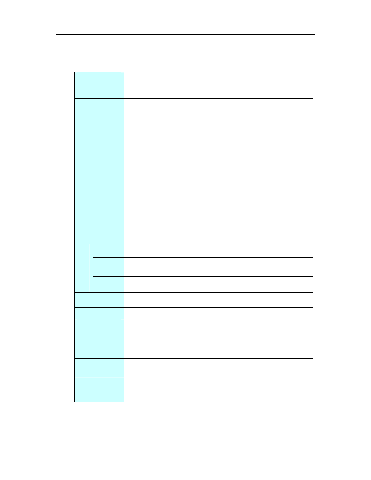
Run-Time Interfaces/Integration Guide
I-A-39
3.3.3.10 EDMA3_DRV_setSrcIndex ()
Prototype EDMA3_DRV_Result EDMA3_DRV_setSrcIndex (
EDMA3_DRV_Handle hEdma, unsigned int lCh, int srcBIdx, int
srcCIdx );
Description DMA source index setup.
It is used to program the source B index and source C index.
SRCBIDX is a 16-bit signed value (2s complement) used for
source address modification between each array in the 2nd
dimension. Valid values for SRCBIDX are between –32768 and
32767. It provides a byte address offset from the beginning of
the source array to the beginning of the next source array. It
applies to both A-synchronized and AB-synchronized transfers.
SRCCIDX is a 16-bit signed value (2s complement) used for
source address modification in the 3rd dimension. Valid values
for SRCCIDX are between –32768 and 32767. It provides a
byte address offset from the beginning of the current array
(pointed to by SRC address) to the beginning of the first source
array in the next frame. It applies to both A-synchronized and
AB-synchronized transfers. Note that when SRCCIDX is
applied, the current array in an A-synchronized transfer is the
last array in the frame, while the current array in an ABsynchronized transfer is the first array in the frame.
<arg1> hEdma [IN] Handle to the EDMA3 Driver Instance.
<arg2> lCh [IN] Logical Channel for which source indices
are to be configured
Arguments
<arg3> srcBIdx [IN] Source B index
<arg4> srcCIdx [IN] Source C index
Return value EDMA3_DRV_SOK or EDMA3_DRV Error Code in case of error.
Calling
constraints
Example result = EDMA3_DRV_setSrcIndex (hEdma, chId, srcbidx,
srccidx);
Comments This function is re-entrant for unique lCh values. It is non-re-
entrant for same lCh value.
See Also
Errors EDMA3_DRV_E_INVALID_PARAM
Page 68

Run-Time Interfaces/Integration Guide
A-40
3.3.3.11 EDMA3_DRV_setDestIndex ()
Prototype EDMA3_DRV_Result EDMA3_DRV_setDestIndex (
EDMA3_DRV_Handle hEdma, unsigned int lCh, int destBIdx,
int destCIdx );
Description DMA destination index setup.
It is used to program the destination B index and destination C
index.
DSTBIDX is a 16-bit signed value (2s complement) used for
destination address modification between each array in the
2nd dimension. Valid values for DSTBIDX are between –32768
and 32767. It provides a byte address offset from the
beginning of the destination array to the beginning of the next
destination array within the current frame. It applies to both
A-synchronized and AB-synchronized transfers.
DSTCIDX is a 16-bit signed value (2s complement) used for
destination address modification in the 3rd dimension. Valid
values are between –32768 and 32767. It provides a byte
address offset from the beginning of the current array
(pointed to by DST address) to the beginning of the first
destination array TR in the next frame. It applies to both Asynchronized and AB-synchronized transfers. Note that when
DSTCIDX is applied, the current array in an A-synchronized
transfer is the last array in the frame, while the current array
in a AB-synchronized transfer is the first array in the frame.
<arg1> hEdma [IN] Handle to the EDMA3 Driver Instance.
<arg2> lCh [IN] Logical Channel for which destination
indices are to be configured.
Arguments
<arg3> destBIdx [IN] Destination B index.
<arg4> destCIdx [IN] Destination C index.
Return value EDMA3_DRV_SOK or EDMA3_DRV Error Code in case of error.
Calling
constraints
Example result = EDMA3_DRV_setDestIndex (hEdma,chId,desbidx,
descidx);
Comments This function is re-entrant for unique lCh values. It is non-re-
entrant for same lCh value.
See Also
Errors EDMA3_DRV_E_INVALID_PARAM
Page 69

Run-Time Interfaces/Integration Guide
I-A-41
3.3.3.12 EDMA3_DRV_setTransferParams ()
Prototype EDMA3_DRV_Result EDMA3_DRV_setTransferParams
(EDMA3_DRV_Handle hEdma, unsigned int lCh, unsigned int
aCnt, unsigned int bCnt, unsigned int cCnt, unsigned int
bCntReload, EDMA3_DRV_SyncType syncType);
Description DMA transfer parameters setup.
It is used to specify the various counts (ACNT, BCNT and
CCNT), B count reload and the synchronization type.
<arg1> hEdma [IN] Handle to the EDMA3 Driver Instance.
<arg2> lCh [IN] Logical Channel for which transfer parameters
are to be configured
Arguments
<arg3> aCnt [IN] Count for 1st Dimension.
ACNT represents the number of bytes within the
1st dimension of a transfer. ACNT is a 16-bit unsigned value
with valid values between 0 and 65535. Therefore, the
maximum number of bytes in an array is 65535 bytes (64K – 1
bytes). ACNT must be greater than or equal to 1 for a TR to be
submitted to EDMA3 Transfer Controller. An ACNT equal to 0 is
considered either a null or dummy transfer. A dummy or null
transfer generates a completion code depending on the
settings of the completion bit fields in OPT.
<arg4> bCnt [IN] Count for 2nd Dimension.
BCNT is a 16-bit unsigned value that specifies
the number of arrays of length ACNT. For normal operation,
valid values for BCNT are between 1 and 65535. Therefore, the
maximum number of arrays in a frame is 65535 (64K – 1
arrays). A BCNT equal to 0 is considered either a null or
dummy transfer. A dummy or null transfer generates a
completion code depending on the settings of the completion
bit fields in OPT.
<arg5> cCnt [IN] Count for 3rd Dimension.
CCNT is a 16-bit unsigned value that specifies
the number of frames in a block. Valid values for CCNT are
between 1 and 65535. Therefore, the maximum number of
frames in a block is 65535 (64K – 1 frames). A CCNT equal to
0 is considered either a null or dummy transfer. A dummy or
null transfer generates a completion code depending on the
settings of the completion bit fields in OPT. A CCNT value of 0
is considered either a null or dummy transfer.
Page 70

Run-Time Interfaces/Integration Guide
A-42
<arg6> bCntReload [IN] Reload value for bCnt.
BCNTRLD is a 16-bit unsigned value used to reload the BCNT
field once the last array in the 2nd dimension is transferred.
This field is only used for A-synchronized transfers. In this
case, the EDMA3CC decrements the BCNT value by 1 on each
TR submission. When BCNT (conceptually) reaches 0, the
EDMA3CC decrements CCNT and uses the BCNTRLD value to
reinitialize the BCNT value.
For AB-synchronized transfers, the EDMA3CC submits the
BCNT in the TR and the EDMA3TC decrements BCNT
appropriately. For AB-synchronized transfers, BCNTRLD is not
used.
<arg7> syncType [IN] Transfer synchronization dimension.
0: A-synchronized. Each event triggers
the transfer of a single array of ACNT
bytes.
1: AB-synchronized. Each event triggers
the transfer of BCNT arrays of ACNT
bytes.
Return value EDMA3_DRV_SOK or EDMA3_DRV Error Code in case of error.
Calling
constraints
Example result = EDMA3_DRV_setTransferParams (hEdma, chId, acnt,
bcnt, ccnt, BRCnt, EDMA3_DRV_SYNC_A);
Comments a) For ACNT, BCNT & CCNT, valid range is 1 to 65535. Value
of 0 will result in a null/dummy transfer
b) BCNT Reload is used when BCNT decrements to 0 (Transfer
request submitted for the last array in 2nd dimension).
Only relevant in A-synchronized transfers.
c) This function is re-entrant for unique lCh values. It is non-
re-entrant for same lCh value.
See Also
Errors EDMA3_DRV_E_INVALID_PARAM
Page 71

Run-Time Interfaces/Integration Guide
I-A-43
3.3.3.13 EDMA3_DRV_chainChannel ()
Prototype EDMA3_DRV_Result EDMA3_DRV_chainChannel
(EDMA3_DRV_Handle hEdma, unsigned int lCh1,
unsigned int lCh2, const EDMA3_DRV_ChainOptions
*chainOptions);
Description Chain the two specified channels.
This API is used to chain two previously allocated
logical (DMA/QDMA) channels.
Chaining is different from Linking. The EDMA3 link
feature reloads the current channel parameter set
with the linked parameter set. The EDMA3 chaining
feature does not modify or update any channel
parameter set; it provides a synchronization event to
the chained channel.
<arg1> hEdma [IN] Handle to the EDMA3 Driver
Instance.
<arg2> lCh1 [IN] Channel to which particular
channel will be chained.
Arguments
<arg3> lCh2 [IN] Channel which needs to be
chained to the first channel.
<arg4> chainOptions [IN] Options such as
intermediate/final interrupts are
required or not, intermediate/final chaining is
enabled or not etc.
Return value EDMA3_DRV_SOK or EDMA3_DRV Error Code in case
of error.
Calling
constraints
Example result = EDMA3_DRV_chainChannel (hEdma, ch1Id,
ch2Id, chainOpt);
Comments a) The channel chaining capability allows the
completion of an EDMA3 channel transfer to
trigger another EDMA3 channel transfer. The
purpose is to provide the ability to chain several
events through one event occurrence.
Chaining is different from linking. The EDMA3 link
feature reloads the current channel parameter set
with the linked parameter set. The EDMA3
chaining feature does not modify or update any
channel parameter set; it provides a
synchronization event to the chained channel.
b) This function is re-entrant for unique lCh1 & lCh2
Page 72

Run-Time Interfaces/Integration Guide
A-44
values. It is non-re-entrant for same lCh1 & lCh2
values.
See Also
Errors EDMA3_DRV_E_INVALID_PARAM
Page 73

Run-Time Interfaces/Integration Guide
I-A-45
3.3.3.14 EDMA3_DRV_unchainChannel ()
Prototype EDMA3_DRV_Result EDMA3_DRV_unchainChannel
(EDMA3_DRV_Handle hEdma, unsigned int lCh);
Description Unchain the specified channel.
<arg1> hEdma [IN] Handle to the EDMA3 Driver
Instance.
Arguments
<arg2> lCh [IN] Channel whose chaining with
the other channel has to be
removed.
Return value EDMA3_DRV_SOK or EDMA3_DRV Error Code in case
of error.
Calling
constraints
Example result = EDMA3_DRV_unchainChannel (hEdma,
chId);
Comments This function is re-entrant for unique lCh values. It is
non-re-entrant for same lCh values.
See Also
Errors EDMA3_DRV_E_INVALID_PARAM
Page 74

Run-Time Interfaces/Integration Guide
A-46
3.3.3.15 EDMA3_DRV_enableTransfer ()
Prototype EDMA3_DRV_Result EDMA3_DRV_enableTransfer
(EDMA3_DRV_Handle hEdma, unsigned int lCh,
EDMA3_DRV_TrigMode trigMode);
Description Start EDMA transfer on the specified channel.
There are multiple ways to trigger an EDMA3
transfer. The triggering mode option allows choosing
from the available triggering modes: Event, Manual
or QDMA.
In event triggered, a peripheral or an externally
generated event triggers the transfer. This API clears
the Event and Event Miss Register and then enables
the DMA channel by writing to the EESR.
In manual triggered mode, CPU manually triggers a
transfer by writing a 1 in the Event Set Register
(ESR/ESRH). This API writes to the ESR/ESRH to
start the transfer.
In QDMA triggered mode, a QDMA transfer is
triggered when a CPU (or other EDMA3 programmer)
writes to the trigger word of the QDMA channel
PaRAM set (auto-triggered) or when the EDMA3CC
performs a link update on a PaRAM set that has been
mapped to a QDMA channel (link triggered). This API
enables the QDMA channel by writing to the QEESR
register.
<arg1> hEdma [IN] Handle to the EDMA3 Driver
Instance.
<arg2> lCh [IN] Channel on which transfer has
to be started.
Arguments
<arg3> trigMode [IN] Mode of triggering start of
transfer (Manual, QDMA or
Event)
Return value EDMA3_DRV_SOK or EDMA3_DRV Error Code in case
of error.
Calling
constraints
Example result = EDMA3_DRV_enableTransfer
(hEdma,chId,EDMA3_DRV_TRIG_MODE_MANUAL);
Comments This function is re-entrant for unique lCh values. It is
non-re-entrant for same lCh value.
See Also
Page 75

Run-Time Interfaces/Integration Guide
I-A-47
Errors EDMA3_DRV_E_INVALID_PARAM
Page 76

Run-Time Interfaces/Integration Guide
A-48
3.3.3.16 EDMA3_DRV_disableTransfer ()
Prototype EDMA3_DRV_Result EDMA3_DRV_disableTransfer
(EDMA3_DRV_Handle hEdma, unsigned int lCh,
EDMA3_DRV_TrigMode trigMode);
Description Disable EDMA transfer on the specified channel.
There are multiple ways by which an EDMA3 transfer
could be triggered. The triggering mode option allows
choosing from the available triggering modes: Event,
Manual or QDMA.
To disable a channel which was previously triggered
in manual mode, this API clears the Secondary Event
Register and Event Miss Register, if set, for the
specific DMA channel.
To disable a channel which was previously triggered
in QDMA mode, this API clears the QDMA Even
Enable Register, for the specific QDMA channel.
To disable a channel which was previously triggered
in event mode, this API clears the Event Enable
Register, Event Register, Secondary Event Register
and Event Miss Register, if set, for the specific DMA
channel.
<arg1> hEdma [IN] Handle to the EDMA3 Driver
Instance.
<arg2> lCh [IN] Channel on which transfer has
to be stopped.
Arguments
<arg3> trigMode [IN] Mode of triggering start of
transfer (Manual, QDMA or
Event)
Return value EDMA3_DRV_SOK or EDMA3_DRV Error Code in case
of error.
Calling
constraints
Example result = EDMA3_DRV_disableTransfer
(hEdma,chId,EDMA3_DRV_TRIG_MODE_MANUAL);
Comments This function is re-entrant for unique lCh values. It is
non-re-entrant for same lCh value.
See Also
Errors EDMA3_DRV_E_INVALID_PARAM
Page 77

Run-Time Interfaces/Integration Guide
I-A-49
3.3.3.17 EDMA3_DRV_disableLogicalChannel ()
Prototype EDMA3_DRV_Result
EDMA3_DRV_disableLogicalChannel
(EDMA3_DRV_Handle hEdma, unsigned int lCh,
EDMA3_DRV_TrigMode trigMode);
Description Disable the event driven DMA channel or QDMA
channel.
This API disables the DMA channel (which was
previously triggered in event mode) by clearing the
Event Enable Register; it disables the QDMA channel
by clearing the QDMA Event Enable Register.
This API should NOT be used for DMA channels which
are not mapped to any hardware events and are used
for memory-to-memory copy based transfers. In case
of that, this API returns error.
<arg1> hEdma [IN] Handle to the EDMA3 Driver
Instance.
<arg2> lCh [IN] DMA/QDMA Channel which
needs to be disabled.
Arguments
<arg3> trigMode [IN] Mode of triggering start of
transfer
Return value EDMA3_DRV_SOK or EDMA3_DRV Error Code in case
of error.
Calling
constraints
Example result = EDMA3_DRV_disableLogicalChannel (hEdma,
chId, EDMA3_DRV_TRIG_MODE_QDMA);
Comments This function is re-entrant for unique lCh values. It is
non-re-entrant for same lCh value.
See Also
Errors EDMA3_DRV_E_INVALID_PARAM
Page 78

Run-Time Interfaces/Integration Guide
A-50
3.3.3.18 EDMA3_DRV_setQdmaTrigWord ()
Prototype EDMA3_DRV_Result EDMA3_DRV_setQdmaTrigWord
(EDMA3_DRV_Handle hEdma, unsigned int
channelId, EDMA3_RM_QdmaTrigWord trigWord);
Description Assign a Trigger Word to the specified QDMA channel.
This API sets the Trigger word for the specific QDMA
channel in the QCHMAP Register. Default QDMA
trigger word is CCNT.
<arg1> hEdma [IN] Handle to the EDMA3 Driver
Instance.
<arg2> channelId [IN] QDMA Channel which needs to
be assigned the Trigger Word.
Arguments
<arg3> trigWord [IN] The Trigger Word for the QDMA
channel. Trigger Word is the
word in the PaRAM Register Set which, when written
to by CPU, will start the QDMA transfer automatically.
Return value EDMA3_DRV_SOK or EDMA3_DRV Error Code in case
of error.
Calling
constraints
Example result = EDMA3_DRV_setQdmaTrigWord (hEdma,
qChId, EDMA3_RM_QDMA_TRIG_DST);
Comments This function is re-entrant for unique lCh values. It is
non-re-entrant for same lCh value.
See Also
Errors EDMA3_DRV_E_INVALID_PARAM
Page 79

Run-Time Interfaces/Integration Guide
I-A-51
3.3.3.19 EDMA3_DRV_setPaRAM ()
Prototype EDMA3_DRV_Result EDMA3_DRV_setPaRAM (
EDMA3_DRV_Handle hEdma, unsigned int lCh, const
EDMA3_DRV_PaRAMRegs newPaRAM);
Description Copy the user specified PaRAM Set onto the PaRAM
Set associated with the logical channel
(DMA/QDMA/Link).
This API takes a PaRAM Set as input and copies it
onto the actual PaRAM Set associated with the
logical channel. OPT field of the PaRAM Set is written
first and the CCNT field is written last.
Caution: It should be used carefully when
programming the QDMA channels whose trigger
words are not CCNT field.
<arg1> hEdma [IN] Handle to the EDMA3 Driver
Instance.
<arg2> lCh [IN] Logical Channel for which new
PaRAM set is specified.
Arguments
<arg3> newPaRAM [IN] Parameter RAM set to be
copied onto existing PaRAM.
Return value EDMA3_DRV_SOK or EDMA3_DRV Error Code in
case of error.
Calling
constraints
Example result = EDMA3_DRV_setPaRAM (hEdma, lCh,
newPaRAM);
Comments This function is re-entrant for unique lCh values. It is
non-re-entrant for same lCh value.
See Also
Errors EDMA3_DRV_E_INVALID_PARAM
Page 80

Run-Time Interfaces/Integration Guide
A-52
3.3.3.20 EDMA3_DRV_getPaRAM ()
Prototype EDMA3_DRV_Result EDMA3_DRV_getPaRAM (
EDMA3_DRV_Handle hEdma, unsigned int lCh, const
EDMA3_DRV_PaRAMRegs *currPaRAM);
Description Retrieve existing PaRAM set associated with
specified logical channel (DMA/QDMA/Link).
<arg1> hEdma [IN] Handle to the EDMA3 Driver
Instance.
<arg2> lCh [IN] Logical Channel for which new
PaRAM set is specified.
Arguments
<arg3> currPaRAM [IN] User gets the existing PaRAM
here.
Return value EDMA3_DRV_SOK or EDMA3_DRV Error Code in
case of error.
Calling
constraints
Example result = EDMA3_DRV_getPaRAM (hEdma, lCh,
&currPaRAM);
Comments This function is re-entrant.
See Also
Errors EDMA3_DRV_E_INVALID_PARAM
Page 81

Run-Time Interfaces/Integration Guide
I-A-53
3.3.3.21 EDMA3_DRV_setPaRAMEntry ()
Prototype EDMA3_DRV_Result EDMA3_DRV_setPaRAMEntry
(EDMA3_DRV_Handle hEdma, unsigned int lCh,
EDMA3_DRV_PaRAMEntry paRAMEntry, unsigned int
newPaRAMEntryVal);
Description Set a particular PaRAM set entry of the specified
PaRAM set
<arg1> hEdma [IN] Handle to the EDMA3 Driver
Instance.
<arg2> lCh [IN] Logical Channel bound to the
Parameter RAM set whose
specified field needs to be set.
Arguments
<arg3> paRAMEntry [IN] Specify the PaRAM set entry
which needs to be set.
<arg4> newPaRAMEntryVal [IN] The new field setting
Return value EDMA3_DRV_SOK or EDMA3_DRV Error Code in
case of error.
Calling
constraints
Example result = EDMA3_DRV_setPaRAMEntry (hEdma,
qChId, EDMA3_DRV_PARAM_ENTRY_DST, (unsigned
int)(dstBuff));
Comments This function is re-entrant for unique lCh values. It is
non-re-entrant for same lCh value.
See Also
Errors EDMA3_DRV_E_INVALID_PARAM
Page 82

Run-Time Interfaces/Integration Guide
A-54
3.3.3.22 EDMA3_DRV_getPaRAMEntry ()
Prototype EDMA3_DRV_Result EDMA3_DRV_getPaRAMEntry
(EDMA3_DRV_Handle hEdma, unsigned int lCh,
EDMA3_DRV_PaRAMEntry paRAMEntry, unsigned int
*paRAMEntryVal);
Description Get a particular PaRAM set entry of the specified
PaRAM set
<arg1> hEdma [IN] Handle to the EDMA3 Driver
Instance.
<arg2> lCh [IN] Logical Channel bound to the
Parameter RAM set whose
specified field needs to be get.
Arguments
<arg3> paRAMEntry [IN] Specify the PaRAM set entry
which needs to be get.
<arg4> paRAMEntryVal [IN] The value of the field
Return value EDMA3_DRV_SOK or EDMA3_DRV Error Code in
case of error.
Calling
constraints
Example result = EDMA3_DRV_getPaRAMEntry (hEdma,
qChId, EDMA3_DRV_PARAM_ENTRY_DST, &dstBuff);
Comments This function is re-entrant.
See Also
Errors EDMA3_DRV_E_INVALID_PARAM
Page 83

Run-Time Interfaces/Integration Guide
I-A-55
3.3.3.23 EDMA3_DRV_setPaRAMField ()
Prototype EDMA3_DRV_Result EDMA3_DRV_setPaRAMField
(EDMA3_DRV_Handle hEdma, unsigned int lCh,
EDMA3_DRV_PaRAMField paRAMField, unsigned int
newPaRAMFieldVal);
Description Set a particular PaRAM set field of the specified
PaRAM set
<arg1> hEdma [IN] Handle to the EDMA3 Driver
Instance.
<arg2> lCh [IN] Logical Channel bound to the
Parameter RAM set whose
specified field needs to be set.
Arguments
<arg3> paRAMField [IN] Specify the PaRAM set field
which needs to be set.
<arg4> newPaRAMFieldVal [IN] The new field setting
Return value EDMA3_DRV_SOK or EDMA3_DRV Error Code in
case of error.
Calling
constraints
Example result = EDMA3_DRV_setPaRAMField (hEdma, lCh,
EDMA3_DRV_PARAM_FIELD_SRCADDR,
newPaRAMFieldVal);
Comments This function is re-entrant for unique lCh values. It is
non-re-entrant for same lCh value.
See Also
Errors EDMA3_DRV_E_INVALID_PARAM
Page 84

Run-Time Interfaces/Integration Guide
A-56
3.3.3.24 EDMA3_DRV_getPaRAMField ()
Prototype EDMA3_DRV_Result EDMA3_DRV_getPaRAMField
(EDMA3_DRV_Handle hEdma, unsigned int lCh,
EDMA3_DRV_PaRAMField paRAMField, unsigned int
*currPaRAMFieldVal);
Description Get a particular PaRAM set field of the specified
PaRAM set
<arg1> hEdma [IN] Handle to the EDMA3 Driver
Instance.
<arg2> lCh [IN] Logical Channel bound to the
Parameter RAM set whose
specified field needs to be get.
Arguments
<arg3> paRAMField [IN] Specify the PaRAM set field
which needs to be get.
<arg4> currPaRAMFieldVal [IN] The value of the field
Return value EDMA3_DRV_SOK or EDMA3_DRV Error Code in
case of error.
Calling
constraints
Example result = EDMA3_DRV_getPaRAMField (hEdma, lCh,
EDMA3_DRV_PARAM_FIELD_SRCADDR,
&currPaRAMFieldVal);
Comments This function is re-entrant.
See Also
Errors EDMA3_DRV_E_INVALID_PARAM
Page 85

Run-Time Interfaces/Integration Guide
I-A-57
3.3.3.25 EDMA3_DRV_setEvtQPriority ()
Prototype EDMA3_DRV_Result EDMA3_DRV_setEvtQPriority
(EDMA3_DRV_Handle hEdma, const
EDMA3_DRV_EvtQuePriority evtQPriObj);
Description Sets EDMA TC priority.
User can program the priority of the Event Queues
at a system-wide level. This means that the user
can set the priority of an IO initiated by either of the
TCs (Transfer Controllers) relative to IO initiated by
the other bus masters on the device (ARM, DSP,
USB, etc)
<arg1> hEdma [IN] Handle to the EDMA3 Driver
Instance.
Argume
nts
<arg2> evtQPriObj [IN] Priority of the Event Queues
Return value EDMA3_DRV_SOK or EDMA3_DRV Error Code in
case of error.
Calling
constraints
Example result = EDMA3_DRV_setEvtQPriority (hEdma,
&evtQPriObj);
Comments This function disables the global interrupts while
modifying the global CC Registers, to make it reentrant.
See Also
Errors EDMA3_DRV_E_INVALID_PARAM
Page 86

Run-Time Interfaces/Integration Guide
A-58
3.3.3.26 EDMA3_DRV_mapChToEvtQ ()
Prototype EDMA3_DRV_Result EDMA3_DRV_mapChToEvtQ
(EDMA3_DRV_Handle hEdma, unsigned int
channelId, EDMA3_RM_EventQueue eventQ);
Description Associate Channel to Event Queue
<arg1> hEdma [IN] Handle to the EDMA3 Driver
Instance.
<arg2> channelId [IN] Logical Channel to which the
Event Queue is to be mapped.
Arguments
<arg3> eventQ [IN] The Event Queue which is to be
mapped to the DMA channel.
Return value EDMA3_DRV_SOK or EDMA3_DRV Error Code in
case of error.
Calling
constraints
Example result = EDMA3_DRV_mapChToEvtQ (hEdma,
channelId, eventQ);
Comments This function disables the global interrupts while
modifying the global CC Registers, to make it reentrant.
See Also
Errors EDMA3_DRV_E_INVALID_PARAM
Page 87

Run-Time Interfaces/Integration Guide
I-A-59
3.3.3.27 EDMA3_DRV_getMapChToEvtQ ()
Prototype EDMA3_DRV_Result EDMA3_DRV_getMapChToEvtQ
( EDMA3_DRV_Handle hEdma, unsigned int
channelId, unsigned int *mappedEvtQ);
Description Get the Event Queue mapped to the specified
DMA/QDMA channel
<arg1> hEdma [IN] Handle to the EDMA3 Driver
Instance.
<arg2> channelId [IN] Logical Channel whose
associated Event Queue is
needed
Arguments
<arg3> mappedEvtQ [IN/OUT] The Event Queue which
is mapped to the
DMA/QDMA channel.
Return value EDMA3_DRV_SOK or EDMA3_DRV Error Code in
case of error.
Calling
constraints
Example result = EDMA3_DRV_getMapChToEvtQ (hEdma,
channelId, &mappedEvtQ);
Comments This function is re-entrant.
See Also
Errors EDMA3_DRV_E_INVALID_PARAM
Page 88

Run-Time Interfaces/Integration Guide
A-60
3.3.3.28 EDMA3_DRV_ setCCRegister ()
Prototype EDMA3_DRV_Result EDMA3_DRV_setCCRegister (
EDMA3_DRV_Handle hEdma, unsigned int re
gOffset,
unsigned int newRegValue);
Description Sets a particular EDMA3 Channel Controller (CC)
register, by specifying the offset and value. Since all
the CC registers are 4 bytes in length, the offset
specified should be 4-bytes aligned in nature.
<arg1> hEdma [IN] Handle to the EDMA3 Driver
Instance.
<arg2> regOffset [IN] CC Register offset whose value
needs to be set.
Arguments
<arg3> newRegValue [IN] New CC Register Value
Return value EDMA3_DRV_SOK or EDMA3_DRV Error Code in
case of error.
Calling
constraints
Example result = EDMA3_DRV_setCCRegister(hEdma,
ccRegOffset, newRegVal);
Comments This function is non re-entrant for users using the
same EDMA handle i.e. working on the same shadow
region. Before modifying a register, it tries to
acquire a semaphore (Driver instance specific), to
protect simultaneous modification of the same
register by two different users. After the successful
change, it releases the semaphore. For users
working on different shadow regions, thus different
EDMA handles, this function is re-entrant.
See Also
Errors EDMA3_DRV_E_INVALID_PARAM
Page 89

Run-Time Interfaces/Integration Guide
I-A-61
3.3.3.29 EDMA3_DRV_ getCCRegister ()
Prototype EDMA3_DRV_Result EDMA3_DRV_getCCRegister (
EDMA3_DRV_
Handle hEdma, unsigned int regOffset,
unsigned int *regValue);
Description Gets a particular EDMA3 Channel Controller (CC)
register, by specifying the offset. Since all the CC
registers are 4 bytes in length, the offset specified
should be 4-bytes aligned in nature.
<arg1> hEdma [IN] Handle to the EDMA3 Driver
Instance.
<arg2> regOffset [IN] CC Register offset whose value
is needed
Arguments
<arg3> regValue [IN/OUT] CC Register Value
Return value EDMA3_DRV_SOK or EDMA3_DRV Error Code in
case of error.
Calling
constraints
Example result = EDMA3_DRV_getCCRegister (hEdma,
ccRegOffset, &ccRegVal);
Comments This function is re-entrant.
See Also
Errors EDMA3_DRV_E_INVALID_PARAM
Page 90

Run-Time Interfaces/Integration Guide
A-62
3.3.3.30 EDMA3_DRV_waitAndClearTcc ()
Prototype EDMA3_DRV_Result EDMA3_DRV_waitAndClearTcc
(EDMA3_DRV_Handle hEdma, unsigned int tccNo);
Description Wait for a transfer completion interrupt to occur.
This is a blocking function that returns when the
IPR/IPRH bit corresponding to the tccNo specified, is
SET. It clears the corresponding bit while returning
also.
<arg1> hEdma [IN] Handle to the EDMA3 Driver
Instance.
Arguments
<arg2> tccNo [IN] TCC, specific to which the
function waits on a IPR/IPRH
bit.
Return value EDMA3_DRV_SOK or EDMA3_DRV Error Code in
case of error.
Calling
constraints
Example result = EDMA3_DRV_waitAndClearTcc (hEdma,
tccNo);
Comments This function is re-entrant for different tccNo.
THIS FUNCTION WAITS FOR THE SPECIFIC BIT
INDEFINITELY (IN A TIGHT LOOP, WITH OUT
ANY DELAY IN BETWEEN). USE IT
CAUTIOUSLY.
See Also
Errors EDMA3_DRV_E_INVALID_PARAM
Page 91

Run-Time Interfaces/Integration Guide
I-A-63
3.3.3.31 EDMA3_DRV_checkAndClearTcc ()
Prototype EDMA3_DRV_Result EDMA3_DRV_checkAndClearTcc
(EDMA3_DRV_Handle hEdma, unsigned int tccNo,
unsigned short *tccStatus);
Description Returns the status of a previously initiated transfer.
This is a non-blocking function that returns the
status of a transfer, based on the IPR/IPRH bit. This
bit corresponds to the tccNo specified by the user. It
clears the corresponding bit, if SET, while returning
also.
<arg1> hEdma [IN] Handle to the EDMA3 Driver
Instance.
<arg2> tccNo [IN] TCC, specific to which the
function checks the status of
the IPR/IPRH bit.
Arguments
<arg3> tccStatus [IN/OUT] Status of the transfer is
returned here. Returns
"TRUE" if the transfer has completed (IPR/IPRH bit
SET), "FALSE" if the transfer has not completed
successfully (IPR/IPRH bit NOT SET).
Return value EDMA3_DRV_SOK or EDMA3_DRV Error Code in
case of error.
Calling
constraints
Example result = EDMA3_DRV_checkAndClearTcc (hEdma,
tccNo, &tccStatus);
Comments This function is re-entrant for different tccNo.
See Also
Errors EDMA3_DRV_E_INVALID_PARAM
Page 92

Run-Time Interfaces/Integration Guide
A-64
3.3.3.32 EDMA3_DRV_Ioctl ()
Prototype EDMA3_DRV_Result
EDMA3_DRV_Ioctl(EDMA3_DRV_Handle hEdma,
EDMA3_DRV_IoctlCmd cmd, void *cmdArg, void
*param);
Description This function provides IOCTL functionality for EDMA3
Driver.
<arg1> hEdma [IN] Handle to the EDMA3 Driver
Instance.
<arg2> cmd [IN] IOCTL command to be
performed.
Arguments
<arg3> cmdArg [IN/OUT] IOCTL command
argument (if any)
<arg4> param [IN/OUT] Device/Cmd specific
argument
Return value EDMA3_DRV_SOK or EDMA3_DRV Error Code in
case of error.
Calling
constraints
Example result = EDMA3_DRV_Ioctl (hEdma,
EDMA3_DRV_IOCTL_SET_PARAM_CLEAR_OPTION,
(void *)1,NULL);
Comments For
'EDMA3_DRV_IOCTL_GET_PARAM_CLEAR_OPTION',
this function is re-entrant.
For
'EDMA3_DRV_IOCTL_SET_PARAM_CLEAR_OPTION',
this function is re-entrant for different EDMA3 Driver
Instances (handles).
See Also
Errors EDMA3_DRV_E_INVALID_PARAM
Page 93

Run-Time Interfaces/Integration Guide
I-A-65
3.3.3.33 EDMA3_DRV_getPaRAMPhyAddr ()
Prototype EDMA3_DRV_Result EDMA3_DRV_getPaRAMPhyAddr
(EDMA3_DRV_Handle hEdma, unsigned int lCh,
unsigned int *paramPhyAddr);
Description Get the PaRAM Set Physical Address associated with
a logical channel. This function returns the PaRAM
Set Phy Address (unsigned 32 bits). Least significant
16 bits of this address could be used to program the
LINK field in the PaRAM Set. Users which program
the LINK field directly SHOULD use this API to get
the associated PaRAM Set address with the LINK
channel.
<arg1> hEdma [IN] Handle to the EDMA3 Driver
Instance.
<arg2> lCh [IN] Logical Channel for which the
PaRAM set offset is required.
Arguments
<arg3> paramPhyAddr [IN/OUT] PaRAM Set Offset
Value
Return value EDMA3_DRV_SOK or EDMA3_DRV Error Code in
case of error.
Calling
constraints
Example result = EDMA3_DRV_getPaRAMPhyAddr (hEdma,
lChId, ¶mPhyAddr);
Comments This function is re-entrant.
See Also
Errors EDMA3_DRV_E_INVALID_PARAM
Page 94

Run-Time Interfaces/Integration Guide
A-66
3.3.3.34 EDMA3_DRV_getInstHandle ()
Prototype EDMA3_DRV_Handle EDMA3_DRV_getInstHandle
(unsigned int phyCtrllerInstId, EDMA3_RM_RegionId
regionId, EDMA3_DRV_Result *errorCode);
Description Returns the previously opened EDMA3 Driver
Instance handle.
This API is used to return the previously opened
EDMA3 Driver's Instance Handle (region specific),
which could be used to call other EDMA3 Driver
APIs. Since EDMA3 Driver does not allow multiple
instances, for a single shadow region, this API is
provided. This API is meant for users who DO NOT
want to / could not open a new Driver Instance and
hence re-use the existing Driver Instance to allocate
EDMA3 resources and use various other EDMA3
Driver APIs.
In case the Driver Instance is not yet opened, NULL
is returned as the function return value whereas
EDMA3_DRV_E_INST_NOT_OPENED is returned in
the errorCode.
<arg1> phyCtrllerInstId [IN] EDMA3 Controller
Instance Id (Hardware instance id, starting from 0).
<arg2> regionId [IN] Shadow Region id for which the
previously opened driver's instance handle is
required.
Arguments
<arg3> errorCode [IN/OUT] Error code while
returning Driver Instance Handle.
Return value EDMA3_DRV_Handle: If successful, this API will
return the driver's instance handle.
Calling
constraints
Example result = EDMA3_DRV_getInstHandle (ctrllerInstId,
regionId, &errorCode);
Comments a) This API returns the previously opened
EDMA3 Driver's Instance handle. The
instance, if exists, could have been opened
by some other user (most probably) or may
be by the same user calling this API. If it was
opened by some other user, then that user
can very well close this instance anytime,
without even knowing that the same instance
handle is being used by other users as well.
In that case, the handle becomes INVALID
and user has to open a valid driver instance
for his/her use.
Page 95

Run-Time Interfaces/Integration Guide
I-A-67
b) This function is re-entrant.
See Also
Errors EDMA3_DRV_E_INVALID_PARAM
EDMA3_DRV_E_INST_NOT_OPENED
Page 96

Run-Time Interfaces/Integration Guide
A-68
3.3.4 Termination
This section should list all the EDMA3 Driver APIs that help in
gracefully terminating the deployed EDMA3 Driver run-time
entities.
Page 97

Run-Time Interfaces/Integration Guide
I-A-69
3.3.4.1 EDMA3_DRV_close ()
Prototype EDMA3_DRV_Result
EDMA3_DRV_close(EDMA3_DRV_Handle
hEdma, void *param)
Description It is used to close an already opened EDMA3
Driver Instance. It should be called when the
EDMA3 driver functionality is no more required
<arg1> hEdma [IN] Handle to the EDMA3
Driver Instance.
Argume
nts
<arg2> param [IN] For possible future use.
Return value EDMA3_DRV_SOK or EDMA3_DRV Error Code in
case of error.
Calling constraints
Example result = EDMA3_DRV_close (hEdma, NULL);
Comments This function disables the global interrupts while
modifying the global Driver data structures, to
make it re-entrant.
See Also
Errors EDMA3_DRV_E_INVALID_PARAM,
EDMA3_DRV_E_OBJ_NOT_OPENED,
EDMA3_DRV_E_RM_CLOSE_FAIL
Page 98

Run-Time Interfaces/Integration Guide
A-70
3.3.4.2 EDMA3_DRV_delete ()
Prototype EDMA3_DRV_Result EDMA3_DRV_delete
(unsigned int phyCtrllerInstId, void param);
Description EDMA3 Driver instance deletion. Use this API to
delete the EDMA3 Driver Object. It should be
called ONCE for each EDMA3 hardware
instance.
Note: It should be called ONLY after closing all
the EDMA3 Driver Instances.
<arg1> phyCtrllerInstId [IN] EDMA3 Controller
Instance Id
(Hardware Instance Id, starting from 0).
Arguments<arg2> param [IN] For possible future use.
Return value EDMA3_DRV_SOK or EDMA3_DRV Error Code in
case of error.
Calling constraints
Example result = EDMA3_DRV_delete (phyCtrllerInstId,
NULL);
Side effects
See Also
Errors EDMA3_DRV_E_INVALID_PARAM,
EDMA3_DRV_E_OBJ_NOT_CLOSED,
EDMA3_DRV_E_INVALID_STATE
Page 99

Run-Time Interfaces/Integration Guide
I-A-71
3.4 EDMA3 Driver Initialization
EDMA3 Driver should be initialized first before it can be used by the
peripheral drivers or application. During initialization, EDMA3 driver
object is created first and then a region specific EDMA3 driver
instance is opened. Following are the APIs which are used for the
initialization:
/* EDMA3 Driver Object Creation */
EDMA3_DRV_Result EDMA3_DRV_create (unsigned int
phyCtrllerInstId, const EDMA3_DRV_GblConfigParams
*gblCfgParams, const void *param)
/* EDMA3 Driver Instance Opening */
EDMA3_DRV_Result EDMA3_DRV_open (unsigned int
phyCtrllerInstId, const EDMA3_DRV_InitConfig *initCfg,
EDMA3_DRV_Result *errorCode)
These APIs should be mandatorily called once by the global
initialization routine or by the user itself, for EDMA3 driver
functioning. Also, they can be called further for other usage.
Note 1: During the initialization sequence, EDMA3 Driver, being an
OS independent module, doesn’t register various interrupt handlers
with the underlying OS. The application which is using the EDMA3
Driver should register the various Interrupt Handlers (ISRs in
Resource Manager) with the underlying OS on which it is running.
Similarly, the application should un-register the previously
registered Interrupt Handlers when the Driver instance is no more
required.
Note 2: While un-registering the interrupt handlers, it should be
taken care by the application that no other applications, using the
interrupt functionality, are functioning. Otherwise, the unregistration done by one application may stop other applications.
The un-registration should be done only when no more
applications, using the interrupt functionality, are functioning.
Page 100

Run-Time Interfaces/Integration Guide
A-72
3.5 API Flow Diagram
Below are the flow diagrams for some EDMA3 Driver APIs which
interact with the
EDMA3 Resource Manager for their functioning.
 Loading...