

Page 1

DVEVM Getting Started Guide
Literature Number: SPRUE66A
August 2006
Page 2

IMPORTANT NOTICE
Texas Instruments Incorporated and its subsidiaries (TI) reserve the right to make corrections, modifications,
enhancements , improvement s, and other c hanges to it s product s and services at any time an d to discontinue any
product or service without notice. Customers should obtain the latest relevant information before placing orders
and should verify that such information is current and complete. All products are sold subject to TI's terms and
conditions of sale supplied at the time of order acknowledgment.
TI warrants perfor mance of its hardware product s to the speci fications appl icable at the tim e of sale in acco rdance
with TI's standard warranty . T esting a nd other quality control techniques are used to the extent TI deems necessary
to support this warranty. Except where mandated by government requirements, testing of all parameters of each
product is not necessarily performed.
TI assumes no liability for applications assistance or customer product design. Customers are responsible for
their products and applications using TI components. To minimize the risks associated with customer products
and applications, customers should provide adequate design and operating safeguards.
TI does not warrant or represent that an y li ce nse , eit her ex pre ss or im pli ed, is gra nte d und er any TI p a tent right,
copyright, mask work ri ght, or other TI inte llectual pr operty rig ht relating to any combinati on, machin e, or process
in which TI products or services are used. Information published by TI regarding third-party products or services
does not constitute a li cense fro m TI to use s uch produc ts or se rvices o r a warranty or endo rsement t here of. Use
of such information may requi re a licens e from a third p arty un der the pa tent s or oth er intell ectual property of the
third party, or a license from TI under the patents or other intellectual property of TI.
Reproduction of info rmation in T I data books or da ta sheet s is permis sible only if reproducti on is without alteration
and is accompanied by all associated warranties, conditions, limitations, and notices. Reproduction of this information with alteration is an unfai r and dece pti ve busine ss pr actic e. TI is not respons ible or li able for such alt ered
documentation.
Resale of TI products or services with statements different from or beyond the parameters stated by TI for that
product or service voi ds all expres s and any impl ied w arrantie s for th e asso ciate d TI pr oduct or servic e and is an
unfair and deceptive business practice. TI is not responsible or liable for any such statements.
Following are URLs where you can obtain information on other Texas Instruments products and application
solutions:
Products Applications
Amplifiers amplifier.ti.com Audio www.ti.com/audio
Data Converters dataconverter.ti.com Automotive www.ti.com/automotive
DSP dsp.ti.com Broadband www.ti.com/broadband
Interface interface.ti.com Digital Control www.ti.com/digitalcontrol
Logic logic.ti.com Military www.ti.com/military
Power Mgmt power.ti.com Optical Networking www.ti.com/opticalnetwork
Microcontrollers microcontroller.ti.com Security www.ti.com/security
Low Power Wireless www.ti.com/lpw Telephony www.ti.com/telephony
Video & Imaging www.ti.com/video
Wireless www.ti.com/wireless
Mailing Address: Texas Instruments
Post Office Box 655303 Dallas, Texas 75265
Copyright © 2006, Texas Instruments Incorporated
Page 3

EVALUATION BOARD/KIT IMPORTANT NOTICE
Texas Instruments (TI) provides the enclosed product(s) under the following conditions:
This evaluation board/kit is intended for use for ENGINEERING DEVELOPMENT, DEMON-
STRA TION, OR EVALUATION PURPOSES ONLY and is not conside red by TI to be a finish ed
end-product fit for gene ral consumer use. Persons handli ng the product(s) must have electronics
training and observe goo d engineering practice st and ard s. As s uc h, the goo ds be ing provided
are not intended to b e complete in term s of required d esign-, marketing- , and/or manufacturi ngrelated protective considerations, including product safety and environmental measures typically found in end pro ducts t hat incorpor ate such sem iconductor co mponent s or circ uit boards.
This evaluation board/kit does not fall within the scope of the European Union directives regarding electromagnetic compatibility, restricted substances (RoHS), recycling (WEEE), FCC,
CE or UL, and therefore may not meet the technical requirements of these directives or other
related directives.
Should this evaluation board/kit not meet the specifications indicated in the User's Guide, the
board/kit may be re turned withi n 30 days from the d ate of del ivery for a full refun d. THE FOREGOING WARRANTY IS THE EXCLUSIVE WARRANTY MADE BY SELLER T O BUYER AND
IS IN LIEU OF ALL OTHER WARRANTIES, EXPRESSED, IMPLIED, OR STATUTORY, INCLUDING ANY WARRANTY OF MERCHANT AB ILITY OR FITNESS FOR ANY PARTICULAR
PURPOSE.
The user assumes all responsibility and liability for proper and safe handling of the goods.
Further, the user indemnifies TI from all claims arising from the handling or use of the goods.
Due to the open construction of the product, it is the user's responsibility to take any and all
appropriate precautions with regard to electrostatic discharge.
EXCEPT TO THE EXTENT OF THE INDEMNITY SET FORTH ABOVE, NEITHER PARTY
SHALL BE LIABLE TO THE OTHER FOR ANY INDIRECT, SPECIAL, INCIDENTAL, OR CONSEQUENTIAL DAMAGES.
TI currently deals with a va rie ty of cu stome rs for prod uct s, and therefore our arran gemen t with
the user is not exclusive.
TI assumes no liability for applications assistance, customer product design, software
performance, or infringement of patents or services described herein.
Please read the User's Guide and, specifically, the Warnings and Restrictions notice in the
User's Guide prior to handling the product. This notice contains important safety information
about temperatures and voltages. Fo r additional informat ion on TI's environme ntal and/or safety
programs, please contact the TI application engineer or visit www.ti.com/esh.
No license is granted under an y patent right or other inte llectual property right of TI co vering or
relating to any machine, process, or combination in which such TI products or services might
be or are used.
Mailing Address:
Texas Instruments
Post Office Box 655303
Dallas, Texas 75265
Copyright © 2006, Texas Instruments Incorporated
Page 4

FCC Warning
This evaluation board/kit is intended for use for ENGINEERING DEVELOPMENT, DEMONSTRA TION, OR EVALUATION PURPOSES ONLY and is not co nsidered by TI t o be a finish ed
end-product fit for general consumer use. It generates, uses, and can radiate radio frequency
energy and has not been tested for compliance with the limits of computing devices pursuant
to part 15 of FCC rules, which are designed to provide reasonable protection against radio
frequency interferen ce. Opera tio n of this equip ment i n other e nviron ment s may c ause interference with radio comm unic ations , in w hich cas e the u ser at hi s ow n expe nse wil l be requ ired to
take whatever measures may be required to correct this interference.
Page 5

About This Guide
Preface
The DVEVM (Digital Video Eval uat ion Module) is an eval ua tio n pl atf or m
that showcases the DM644x architecture and lets users evaluate the
power and performance of the DM644x as a Multimedia engine. The
intended audience is the user who is developing Linux-based software on
the DM644x ARM core.
The DVEVM does not expose the DSP co re for software development,
but rather treats it as a " black b ox" for running off-the-shel f codecs . Th e
DVSDK upgrade allows you to add the abi lity to dev el op app li cat ion s for
the DSP side. In addition, the DVSDK adds a full Linux license.
This guide gives you overview information about the board and the
software provided w ith the board. It is intended to be used as th e initial
"getting to know you" document for the DVEVM. Other documents
provide more in-depth information. See the DVEVM documentation index
for a complete list of documents that have been included with the product.
Additional Documents and Resources
You can use the following sources to supplement this user’s guide:
❏ DaVinci EVM Home at Spectrum Digital:
http://c6000.spectrumdigital.com/davincievm/
❏ TI Linux Community for DaVinci Processors:
http://linux.davincidsp.com
❏ Codec Engine Application Developer's Guide (SPRUE67)
Notational Conventions
This document uses the following conventions:
❏ Program listings, program examples, and interactive displays are
shown in a mono-spaced font. Examples use bold for emphasis,
and interactive displays use bold to distinguish commands that you
enter from items that the system displays (such as prompts,
command output, error messages, etc.).
❏ Square brackets ( [ and ] ) identify an option al parameter. If you use
an optional parameter, you specify the information within the
v
Page 6
Trademarks
Trademarks
brackets. Unless t he sq uar e brac k ets a re in a bold typeface, do not
enter the brackets themselves.
The Texas Instruments logo and Texas
Instruments are registered trade marks of Texas
Instruments. Trademarks of Texas Instruments
include: TI, DaVinci, the DaVinci logo, XDS, Code
Composer, Code Composer Studio, Probe Point,
Code Explorer, DSP/BIOS, RTDX, Online DSP
Lab, DaVinci, TMS320, TMS320C54x,
TMS320C55x, TMS320C62x, TMS320C64x,
TMS320C67x, TMS320C5000, and
TMS320C6000.
MS-DOS, Windows, and Windows NT are trademarks of Microsoft
Corporation.
UNIX is a registered trad emark of The Open Grou p in the Un ited States
and other countries.
Linux is a registered trademark of Linus Torvalds.
Solaris, SunOS, and Java are trademarks or reg istered trademarks of
Sun Microsyst ems, Inc.
All other brand, product na mes, and service names are trademarks or
registered trademarks of their respective companies or organizations.
vi
Page 7

Contents
1 DVEVM Overview . . . . . . . . . . . . . . . . . . . . . . . . . . . . . . . . . . . . . . . . . . . . . . . . . . . . . . . . . . .1-1
This chapter introduces the DVEVM (Digital Video Evaluation Module).
1.1 Welcome! . . . . . . . . . . . . . . . . . . . . . . . . . . . . . . . . . . . . . . . . . . . . . . . . . . . . . . . . . . . .1-2
1.2 What’s in this Kit?. . . . . . . . . . . . . . . . . . . . . . . . . . . . . . . . . . . . . . . . . . . . . . . . . . . . . .1-3
1.3 What’s on the Board?. . . . . . . . . . . . . . . . . . . . . . . . . . . . . . . . . . . . . . . . . . . . . . . . . . .1-4
1.4 What’s Next? . . . . . . . . . . . . . . . . . . . . . . . . . . . . . . . . . . . . . . . . . . . . . . . . . . . . . . . . .1-5
2 DVEVM Hardware Setup . . . . . . . . . . . . . . . . . . . . . . . . . . . . . . . . . . . . . . . . . . . . . . . . . . . . .2-1
This chapter tells you how to set up the DVEVM hardware.
2.1 Setting Up the Hardware . . . . . . . . . . . . . . . . . . . . . . . . . . . . . . . . . . . . . . . . . . . . . . . .2-2
2.2 Connecting to a Console Window . . . . . . . . . . . . . . . . . . . . . . . . . . . . . . . . . . . . . . . . .2-6
3 Running the Demonstration Software . . . . . . . . . . . . . . . . . . . . . . . . . . . . . . . . . . . . . . . . . .3-1
This chapter explains how to run the software demos provided with the DVEVM.
3.1 Default Boot Configuration . . . . . . . . . . . . . . . . . . . . . . . . . . . . . . . . . . . . . . . . . . . . . . .3-2
3.2 Starting the Standalone Demos . . . . . . . . . . . . . . . . . . . . . . . . . . . . . . . . . . . . . . . . . . .3-2
3.3 Running the Standalone Demos. . . . . . . . . . . . . . . . . . . . . . . . . . . . . . . . . . . . . . . . . . .3-3
3.3.1 About the Encode + Decode Demo . . . . . . . . . . . . . . . . . . . . . . . . . . . . . . . .3-5
3.3.2 About the Encode Demo . . . . . . . . . . . . . . . . . . . . . . . . . . . . . . . . . . . . . . . .3-6
3.3.3 About the Decode Demo . . . . . . . . . . . . . . . . . . . . . . . . . . . . . . . . . . . . . . . .3-8
3.3.4 About the Third Party Menu . . . . . . . . . . . . . . . . . . . . . . . . . . . . . . . . . . . . . .3-9
3.4 Running the Network Demo . . . . . . . . . . . . . . . . . . . . . . . . . . . . . . . . . . . . . . . . . . . . .3-10
4 DVEVM Software Setup . . . . . . . . . . . . . . . . . . . . . . . . . . . . . . . . . . . . . . . . . . . . . . . . . . . . .4-1
This chapter explains how to use the software provided with the DVEVM.
4.1 Software Overview . . . . . . . . . . . . . . . . . . . . . . . . . . . . . . . . . . . . . . . . . . . . . . . . . . . . .4-2
4.1.1 Command Prompts in This Guide . . . . . . . . . . . . . . . . . . . . . . . . . . . . . . . . .4-3
4.1.2 Software Components . . . . . . . . . . . . . . . . . . . . . . . . . . . . . . . . . . . . . . . . . .4-4
4.2 Preparing to Install . . . . . . . . . . . . . . . . . . . . . . . . . . . . . . . . . . . . . . . . . . . . . . . . . . . . .4-5
4.3 Installing the Software . . . . . . . . . . . . . . . . . . . . . . . . . . . . . . . . . . . . . . . . . . . . . . . . . .4-6
4.3.1 Installing the Target Linux Software. . . . . . . . . . . . . . . . . . . . . . . . . . . . . . . .4-6
4.3.2 Installing the DVEVM Software . . . . . . . . . . . . . . . . . . . . . . . . . . . . . . . . . . .4-7
4.3.3 Installing the A/V Demo Files . . . . . . . . . . . . . . . . . . . . . . . . . . . . . . . . . . . . .4-8
4.3.4 Exporting a Shared File System for Target Access . . . . . . . . . . . . . . . . . . . .4-8
4.3.5 Testing the Shared File System. . . . . . . . . . . . . . . . . . . . . . . . . . . . . . . . . . .4-9
4.3.6 Configuring the Boot Setup for PAL Video Users. . . . . . . . . . . . . . . . . . . . .4-10
vii
Page 8

Contents
4.4 Setting Up the Build/Development Environment . . . . . . . . . . . . . . . . . . . . . . . . . . . . .4-11
4.4.1 Writing a Simple Program and Running it on the DVEVM . . . . . . . . . . . . . .4-11
4.5 Rebuilding the DVEVM Software for the Target. . . . . . . . . . . . . . . . . . . . . . . . . . . . . .4-12
4.6 Building a New Linux Kernel. . . . . . . . . . . . . . . . . . . . . . . . . . . . . . . . . . . . . . . . . . . . .4-12
4.7 Booting the New Linux Kernel . . . . . . . . . . . . . . . . . . . . . . . . . . . . . . . . . . . . . . . . . . .4-14
4.8 Installing Upgrades. . . . . . . . . . . . . . . . . . . . . . . . . . . . . . . . . . . . . . . . . . . . . . . . . . . .4-14
A Additional Procedures . . . . . . . . . . . . . . . . . . . . . . . . . . . . . . . . . . . . . . . . . . . . . . . . . . . . . . A-1
This appendix describes optional procedures you may use depending on your setup and specific
needs.
A.1 Running the Demos from the Command Line . . . . . . . . . . . . . . . . . . . . . . . . . . . . . . . . . . . . . . . A-2
A.2 Changing the Video Input/Output Methods . . . . . . . . . . . . . . . . . . . . . . . . . . . . . . . . . . . . . . . . . A-6
A.3 Putting Demo Applications in the Third-Party Menu. . . . . . . . . . . . . . . . . . . . . . . . . . . . . . . . . . . A-9
A.4 Setting Up a TFTP Server . . . . . . . . . . . . . . . . . . . . . . . . . . . . . . . . . . . . . . . . . . . . . . . . . . . . . A-11
A.5 Alternate Boot Methods . . . . . . . . . . . . . . . . . . . . . . . . . . . . . . . . . . . . . . . . . . . . . . . . . . . . . . . A-12
A.6 Installing Components Under Windows . . . . . . . . . . . . . . . . . . . . . . . . . . . . . . . . . . . . . . . . . . . A-16
A.7 Rebuilding DSP/BIOS Link. . . . . . . . . . . . . . . . . . . . . . . . . . . . . . . . . . . . . . . . . . . . . . . . . . . . . A-17
A.8 Restoring and Updating the DVEVM Hard Disk Drive . . . . . . . . . . . . . . . . . . . . . . . . . . . . . . . . A-18
Contents viii
Page 9
Chapter 1
DVEVM Overview
This chapter introduces the DVEVM (Digital Video Evaluation Module).
Topic Page
1.1 Welcome! . . . . . . . . . . . . . . . . . . . . . . . . . . . . . . . . . . . . . . . . . . . . . . . 1–2
1.2 What’s in this Kit?. . . . . . . . . . . . . . . . . . . . . . . . . . . . . . . . . . . . . . . . 1–3
1.3 What’s on the Board? . . . . . . . . . . . . . . . . . . . . . . . . . . . . . . . . . . . . . 1–4
1.4 What’s Next? . . . . . . . . . . . . . . . . . . . . . . . . . . . . . . . . . . . . . . . . . . . . 1–5
1-1
Page 10
Welcome!
1.1 Welcome!
Your new DVEVM (Digital Video Evaluation
Module) will allow you to evaluate TI’s new
TM
DaVinci
Technology and the DM644x
architecture.
This technology brings together system- solu tion
components tailored for efficien t and co mpell ing
digital video and audio.
1-2
The intended audience is a user developing Linux-based software on the
DM644x ARM core. The DVEVM does not expose the DSP core for
software development, but rather treats it as a "black box" for running offthe-shelf codecs. Separate upgrade kits from Texas Instruments will
provide tools and software for DSP development.
Page 11

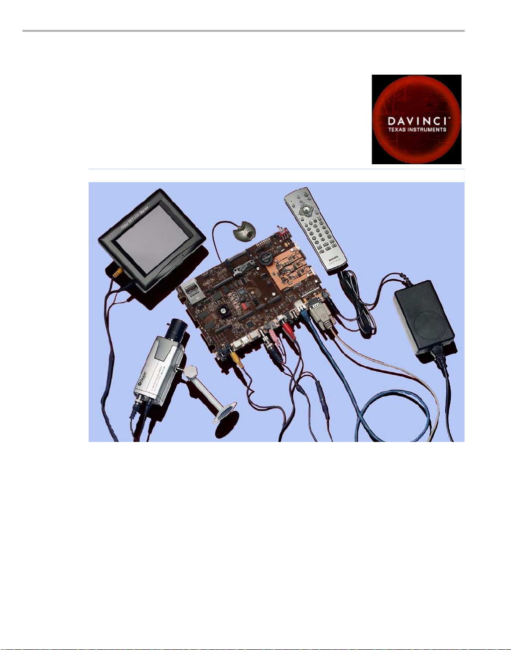
1.2 What’s in this Kit?
Your DVEVM kit contains the following hardware items. Section 2.1,
Setting Up the Hardware tells how to connect these components.
❏ DVEVM Board (SDI P/N 702050). This board contains a DaVinci
❏ Hard Disk Drive (Samsung P/N MP0402H). The hard drive provided
❏ CCD Camera (Swann P/N SW-C-C500R). This camera provides
❏ LCD Display (Delvcam P/N DELVPRO56 (NTSC) / DELVPRO56PL
What’s in this Kit?
TMS320DM6446 dual-core device with an ARM9 and C64+ DSP for
development of applications that use both a general-purpose
processor and an accelerated DSP processor.
with the DVEVM is a 2.5" Spinpoint drive with 40 GB of storage. The
drive speed in 5 400 RP M and it h as an 8M B cach e. The dr ive is an
Ultra ATA 66/100/133 IDE. Software is preloaded on the DVEVM
board’s hard disk drive.
NTSC or PAL video imaging for DaVinci applications.
(PAL) ). The Delvcam LCD display provided with the DVEVM kit has
a 5.6" screen and 32 0x240 pixels. Cables and a power supply are
provided. The NTSC ver sion s upp or ts has a 110 VAC power supply.
The PAL version has a 220 VAC power supply.
❏ PC Desktop Microphone (Labtec Verse 333). The microphone
provides a way to capture audio for use by DaVinci applications.
❏ IR Remote Control (Phillips Magnavo x P/N PM4S EFM7N D). This
universal remote control is included to provide a user interface to the
demo applications.
❏ A/V Cables. Cables used to connect the DVEVM board to peripheral
devices and to a host Li nux workstation used for developm ent are
provided in the kit.
The DVEVM kit also comes with the following software CDs. Information
about how to use the software components is provided in Chapter 4.
❏ DaVinci Digital Video Evaluation Kit.
❏ TI DaVinci Demonstration Version of MontaVista Linux Pro v4.0
Target.
❏ TI DaVinci Demonstration Version of MontaVista Linux Pro v4.0
Tools.
P
D
V
D
❏ Additional software CDs are provided with DVDP upgrade kits.
DVEVM Overview 1-3
Page 12
What’s on the Board?
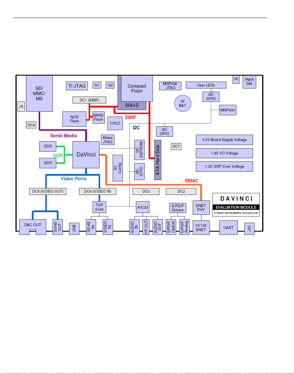
1.3 What’s on the Board?
The DVEVM comes loaded with peripherals your multimedia applications
may need to make use of. T he hard d rive on th e boar d also comes pr eloaded with demonstration software. The following block diagram shows
the major hardware components.
1-4
Diagram provided courtesy of Spectrum Digital Inc.
Figure 1–1 DVEVM Hardware Block Diagram
For more information about the DVEVM hardware, see the DaVinci EVM
website at http://c6000.spectrumdigital.com/davincievm/.
The DaVinci EVM incorporates a battery holder to provide backup power
to the MSP430’s real-ti me clock when the power is not ap plied to the
board. The battery is not included in the kit. See the Spectrum Digital
DaVinci EVM Technical Reference for suggested battery part numbers.
Page 13

1.4 What’s Next?
What’s Next?
To get started evaluating the DVEVM and developing applications for the
DM644x, begin by using this Getting Started guide. It will step you
through connecting the hardware, testing the software, and beginning to
develop applications.
When you are ready for more information about DaVinci T echnology and
the DM644x architecture, see the following:
❏ DaVinci EVM Home at Spectrum Digital:
http://c6000.spectrumdigital.com/davincievm/
❏ TI Linux Community for DaVinci Processors:
http://linux.davincidsp.com
❏ Codec Engine Application Developer's Guide (SPRUE67)
❏ Other PDF documents on the CDs included with the DVEVM
DVEVM Overview 1-5
Page 14

1-6
Page 15
Chapter 2
DVEVM Hardware Setup
This chapter tells you how to set up the DVEVM hardware.
Topic Page
2.1 Setting Up the Hardware. . . . . . . . . . . . . . . . . . . . . . . . . . . . . . . . . . . 2–2
2.2 Connecting to a Console Window . . . . . . . . . . . . . . . . . . . . . . . . . . . 2–6
2-1
Page 16
Setting Up the Hardware
2.1 Setting U p the Hardware
To set up the hardware provided with the DV EVM, use the steps in th e
sections that foll ow. You may skip sect ions if you do not ne ed to ac cess
a particular peripheral . Fo r ex amp le, if you do no t n eed to use the serial
cable, skip that section.
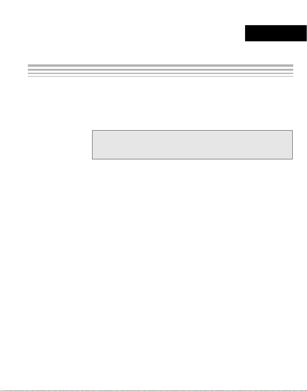
1) The DVEVM is s ensitive to s tatic discharges.
Use a grounding strap or other device to
prevent damaging the board.
Be sure to connect communication cables
before applying power to any equipment.
2) If you use PAL video, set switch 10 on the S3 (USER) bank of
switches to On. If you use NTSC video, set this switch to Off. See
Figure 1–1 for S3 switch bank location.
3) Connect the yellow vide o cable to the uppe r-right Video Out jac k on
the DVEVM and the LCD display Video Input as shown below.
2-2
See Section A.2, Changing the Video Input/Output Methods for
information about using S-Video or Component video.
Page 17
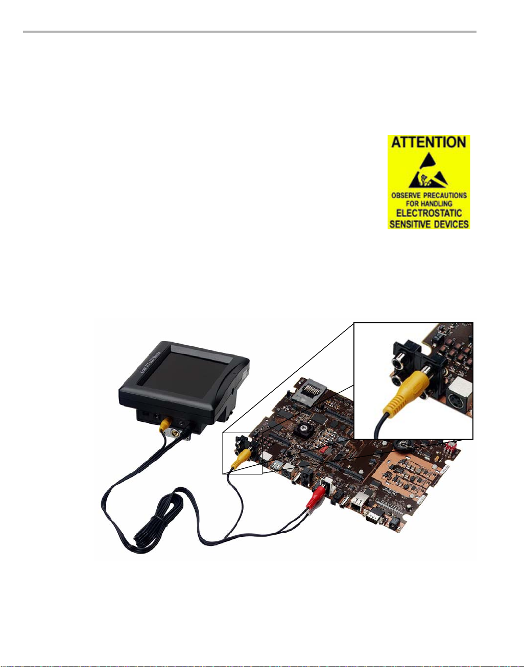
Setting Up the Hardware
4) Connect the red and white audio cables to the DVEVM Audio Output
and the LCD display R/L Audio Input jacks as shown below:
5) Connect the BNC-to-RCA connector to the coax cable. Then connect
the coax cable to the video camera and the DVEVM Video Input.
6) Connect the power jack for the video camera. T o be ESD safe, do not
plug in the other end of the camera power cord until the later step that
instructs you to do so.
See Section A.2, Changing the Video Input/Output Methods for
information about using S-Video or Component video.
DVEVM Hardware Setup 2-3
Page 18
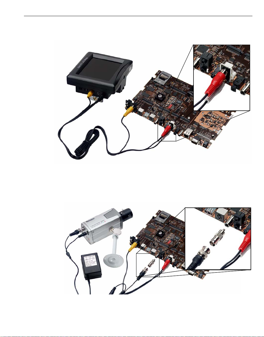
Setting Up the Hardware
7) Connect the microphone to the DVEVM.
8) Connect the power cable to the DVEVM Power Jack on the board. T o
be ESD safe, do not plug in the other end of the cable yet.
9) If you will use the Ethernet connection, connect the Ethernet cable to
the Ethernet Port on the DVEVM and to an Ethernet network port.
If you do not connect the board's Ether net controller to a computer
running a DHCP server, booting the board will take several additional
minutes.
2-4
Page 19

Setting Up the Hardware
10) If you pla n to use th e UART port for a co nsole windo w, connect the
RS232 null modem cable to the DVEVM UART port and the a CO M
port on your host Linux worksta tion. See Section 2.2 , Conn ec ting t o
a Console Window for more about using a console window.
11) Plug in the LCD display to a power supply.
12) Plug in the NTSC/PAL video camera to a power supply.
13) Plug in the DVEVM boar d to a power supply.
14) Power on the LCD display.
15) Power on the DVEVM board.
16) The ini tial screen of the demo softwa re should be d isplayed on th e
LCD display. Use the IR remote to run the softwar e as desc ribed in
Chapter 3.
Note that there will be a DHCP-related de lay if there is no network
connection.
DVEVM Hardware Setup 2-5
Page 20

Connecting to a Console Window
2.2 Connecting to a Console Window
You can open a console window that al lows you to watch and interrupt
DVEVM boot messages by following these steps:
1) Connect a serial cable between the serial port on the DVEVM and the
serial (COM) port on a PC.
2) Run a HyperTerminal ses sion on the PC and c onfigure it to con nect
to that serial port.
3) When you power on the DVEVM, you will see boot sequence
messages. You can press a key to in terrupt the boot seq uence and
type commands in the U-Boot command shell. In this guide,
commands to be typed in the U-Boot shell are indicated by an
EVM # prompt.
2-6
Page 21
Chapter 3
Running the Demonstration Software
This chapter explains how to ru n the software demos provide d with the
DVEVM.
Topic Page
3.1 Default Boot Configuration. . . . . . . . . . . . . . . . . . . . . . . . . . . . . . . . . 3–2
3.2 Starting the Standalone Demos. . . . . . . . . . . . . . . . . . . . . . . . . . . . . 3–2
3.3 Running the Standalone Demos . . . . . . . . . . . . . . . . . . . . . . . . . . . . 3–3
3.4 Running the Network Demo . . . . . . . . . . . . . . . . . . . . . . . . . . . . . . . 3–10
3-1
Page 22

Default Boot Configuration
3.1 Default Boot Configuration
Out of the box, the DVEVM starts the demos automatic ally after a few
seconds when you power up the board. It does not require an NFS mount
or a TFTP server to run the standard demos. A DHCP server is required
by default; the DHCP service provided by most routers is sufficient to run
the demos. By default, the DHCP server obtains dynamic IP addresses.
To abort the standard boot, press an y key in the console window (se e
Section 2.2). Also see Section A.5, Alternate Boot Methods if you want to
change the boot configuration.
3.2 Starting the Standalone Demos
When you connect the DV EVM hardwar e, the pre-l oaded exam ples run
automatically on the LCD d isplay. These examples e ncode and decode
audio, video, and speech. There are two ways to use the demos:
❏ Standalone. This is the default power-on mode. The demos run
automatically with n o c onn ectio n to a workstation in the defa ult boo t
configuration.
❏ Command line. Once you have connected the DVEVM to a
workstation and installed the necessary software (as described in
Section 4.3.1, Installing the Target Linux Software), you can run th e
demos from the board’s Linux command line as described in Section
A.1, Running the Demos from the Command Line.
3-2
Once the DVEVM board h as booted, the LCD display should show a
picture of the remote control. You use the IR remote to control the demos.
To use the demos in standalone mode, follow these steps:
1) Check to make sure the batteries are installed in your IR remote.
2) The initial sc reen sho ws a di agram of the I R remo te, whic h you us e
to run the standalone demo s. Take a minute to look at the functions
of the various buttons.
3) Since this is a universal remote, you ma y need to set it to use the
codes necessary to run the DVEVM demos. T o do this, hold down the
"Code Search" button until the red light on the remote stays lit. Then
press the "DVD" button and enter "020" as the code.
4) If you accidentally put th e remote in TV or some other mode, press
"DVD" to return the remote to the correct mode.
5) If the remote does no t accept the DVD+020 code, do a full reset by
removing the batteries, pressing the power key for at least a minute,
then reinserting the batteries. Then program the remote as in Step 3.
Page 23

3.3 Running the Standalone Demos
1) Press "Play" or "OK" on the remote to move from the remote control
diagram to the main menu screen, which looks like this:
Running the Standalone Demos
The Encode + Decode demo allows you to record and playback
video. The Encode demo records audio/speech and video in the
formats you select. The Decode demo plays audio/speech and video
files you select. The Third-Party Menu can be used to add additional
demos (see Section A.3, Putting Demo Applications in the Third-
Party Menu).
2) Use the up and down arrows to change which demo is selected.
Then, press "OK" or "Play" to switch to the selected demo. (You can
quit out of the demos completely at this point by pressing "Power".)
3) Within a demo, you start at the settings
screen, where you see the controls
you can use to run the demo at the
bottom of the screen and the current
settings in the upper-right.
For example, the Encode demo allows
you to set the vide o for mat and the b it
rate at which video should be encoded.
Fixed settings are also shown here.
4) Use the up and down arrows to move to a setting you want to change.
Running the Demonstration Software 3-3
Page 24

Running the Standalone Demos
5) Use the left and right arrows to cycle through the options until the
setting you want is shown.
6) Press "Play" to begin the EncodeDecode and Decode demos. Press
"Rec" (record) twice to begin the Encode demo. Press "Stop" to
return to the main menu.
7) While the demo runs, data about the settings, p rocessor load, and
rates are shown. Static settings are on the right. Dynamic data
reporting is on the left. For example:
8) This information o verlay s the vi deo; as a resul t the vide o you s ee is
darker than the actual video . To hide the informa tion display so that
you can better see the video, press the "Info/Select" button on the IR
remote. Y ou can change the transparency of the OSD (overlay) while
running a demo by using the left and right arrows on the remote.
3-4
9) Press "Stop" or "Pause" when yo u want to end or pause a demo.
Press "Stop" from the settings screen, you go back to the main menu.
The demos use the Codec En gine to al lo w GP P -sid e app li ca tio ns to run
algorithms transparently on the DSP.
You may notice t hat the DS P CPU l oad is in itially high, even if the DSP
is not running any a lgorithms. The CPU load starts at 100% while the
DSP is booting and then decr eases while the DSP waits for work to be
requested by the GPP. Even if DSP is idle, it may take a short amount of
time (several seconds) for the CPU load to settle to zero. This is because
the Codec Engine’s CPU load calculation includes a small amount of
history.
Page 25

3.3.1 About the Encode + Decode Demo
The Encode + Decode demo allows you to rec ord and playback video .
Video input comes from the ca mera, it is encoded, then dec oded, and
sent to the LCD display.
Running the Standalone Demos
The Encode + Decode d oes only video proc essing; it does not enc ode
and decode audio or s peech. The supported video algorithm is H.264
Baseline Profile (.264 file exte ns ion ).
Table 3–1 IR Remote Buttons for Encode + Decode Demo
IR Remote Button Mode Action Performed
Up/Down -- -- no action -Left/Right Setup Change resolution (ZOOM, CIF, D1)
Play or OK Setup Begin demo
Record -- -- no action -Info/Select Setup Show / hide block diagram for demo
Info/Select Run Toggle information display
Left/Right Run Change information transparency level
Pause Run Pause demo (press Play to resume)
Stop Setup / Run Return to previous screen
Running the Demonstration Software 3-5
Page 26

Running the Standalone Demos
The application runs on the ARM using Linux. The video signal is passed
to video encoders and decoders on the DSP by the Codec Engine.
Shared memory is used when passing data.
To use this demo from the command line, see Section A.1.1,
Encode/Decode Demo Command Line.
3.3.2 About the Encode Demo
Like the Encode + Decode demo, the Encode demo also encodes video.
In addition, it also encodes audio or speech. The audio/speech source is
the microphone.
The encoded data is written to files on the DVEVM’s hard disk drive. The
possible filenames are demo.264, demo.mpeg4, demompeg4.g711, and
demo264.g711. Older versions of these files are overwritten as needed.
Output is not decoded and sent to the LCD display or speakers other than
to show the settings and dynamic data collected about the load and rates.
3-6
Note that you can use only a speech encoder, not an audio encoder. The
supported video algorithms are MPEG4 (.mpeg4 file extension) and
H.264 (.264 file extension). The supported speech algorithm is G.711
(.g711 extension).
Page 27

Running the Standalone Demos
Table 3–2 IR Remote Buttons for Encode Demo
IR Remote Button Mode Action Performed
Up/Down Setup Change option selection
Left/Right Setup Change setting of selected option
Play Setup Switch to decode demo setup
Record (twice)
or OK
Info/Select Setup Show / hide block diagram for demo
Info/Select Run Toggle information display
Left/Right Run Change information transparency level
Pause Run Pause demo (press Play to resume)
Stop Setup / Run Return to previous screen
Setup Begin encode demo
(There is no display for encode demo
behind the information.)
The application runs on the ARM using Linux. The video and audio
signals are passed to encoders on the DSP by the Codec Engine. Shared
memory is used when passing data.
To use this demo from the command line , see Section A.1.2, Encode
Demo Command Line.
Running the Demonstration Software 3-7
Page 28

Running the Standalone Demos
3.3.3 About the Decode Demo
The Decode demo pla ys audio/speech and video fil es you select. You
can select a source video file and a source audio or speech file. Use the
left and right arrow button s to choose from the dem o files and the files
created by the Encode demo, which are stored on the DVEVM’s hard disk
drive. The decoded signals are sent to the LCD display and speakers.
3-8
The supported video algorithms are MPEG4 (.mpeg4 file extension),
H.264 (.264 file extension) and MPEG2 (.m2v file extension).
The supported audio algorithms are AAC (.aac file extension) and
MPEG1 Layer 2 (.mp2 file extension). The supported speech algorithm is
G. 711 (.g711 file extension).
Table 3–3 IR Remote Buttons for Decode Demo
IR Remote Button Mode Action Performed
Up/Down -- -- no action -Left/Right Setup Select a different file combination
Play or OK Setup Begin decode demo
Record -- -- no action -Info/Select Setup Show / hide block diagram for demo
Info/Select Run Toggle information display
Page 29

Table 3–3 IR Remote Buttons for Decode Demo
IR Remote Button Mode Action Performed
Left/Right Run Change information transparency level
Pause Run Pause demo (press Play to resume)
Stop Setup / Run Return to previous screen
The application runs on the ARM using Linux. The video and audio
signals are passed to decoders on the DSP by the Codec Engine. Shared
memory is used when passing data.
To use this demo from the command line, see Se ction A.1.3, Decode
Demo Command Line.
3.3.4 About the Third Party Menu
The Third-Party Menu can be used to add additional demos. See Section
A.3, Putting Demo Applications in the Third-Party Menu.
Running the Standalone Demos
Running the Demonstration Software 3-9
Page 30

Running the Network Demo
3.4 Running the Network Demo
As an example of standard TCP/IP networking support, the DVEVM
examples include a smal l HTTP web server. This web server is started
on the GPP-side as part of the Linux startup sequence. It conf igured to
service requests from web browsers on the standard TCP/IP port 80.
After the DVEVM boar d has bo oted, c onnec t a PC to the s ame n etwork
to which the DVEVM board is connected. Enter a URL of the form
"http://ip-address-of-dvevm" in a web browser (for example, Internet
Explorer, Firefox, or Opera). The IP address of the board is shown in the
lower-right corner of the main menu of the A/V demos.
You should see a web page wi th information about DaVinc i technology
and the DVEVM software.
3-10
Use this web page to interact with the board and run the A/V demos
described in Section 3.3, Running the Standalone Demos. Two simple
CGI scripts on the DVEVM enable you to start the demos (assuming they
are not already running) and see what processes are running on the
board. If you want to see the demo started from the web page, be sure to
exit the demo first (use the Power button from the main menu).
The web server software is an open-source package called THTTPD
(http://www.acme.com/software/thttpd/). It is designed to be small, fast,
and portable. The source code is included with the DVEVM software. Y ou
can get the latest version directly from the web. The web server and CGI
scripts are installed on the target in the /opt/dvevm/web directory.
Page 31

Chapter 4
DVEVM Software Setup
This chapter explains how to use the software provided with the DVEVM.
Topic Page
4.1 Software Overview . . . . . . . . . . . . . . . . . . . . . . . . . . . . . . . . . . . . . . . 4–2
4.2 Preparing to Install . . . . . . . . . . . . . . . . . . . . . . . . . . . . . . . . . . . . . . . 4–5
4.3 Installing the Software . . . . . . . . . . . . . . . . . . . . . . . . . . . . . . . . . . . . 4–6
4.4 Setting Up the Build/Development Environment . . . . . . . . . . . . . . 4–11
4.5 Rebuilding the DVEVM Software for the Target . . . . . . . . . . . . . . . 4–12
4.6 Building a New Linux Kernel . . . . . . . . . . . . . . . . . . . . . . . . . . . . . . 4–12
4.7 Booting the New Linux Kernel . . . . . . . . . . . . . . . . . . . . . . . . . . . . . 4–14
4.8 Installing Upgrades. . . . . . . . . . . . . . . . . . . . . . . . . . . . . . . . . . . . . . 4–14
4-1
Page 32

Software Overview
4.1 Software Overview
To begin developing applications, you need to install the DVEVM
development environment. This section outlines the steps required to
load the DVEVM softwa re onto the de velop ment hos t. You will need the
three DVEVM distribution CDs or the files they contain to get started.
The DaVinci software approach provides interoperable, optimized,
production-ready video and audio codecs that leverage DSP and
integrated accelerators. These codecs are built into configurable
frameworks, and are presented via published APIs within popular
operating systems (such as Linux) for rapid software implementation.
The DVEVM provides for development on the ARM side. Developers
treat the DSP-side as a black box that is accessible through a set of APIs.
If you want to program the DSP- side directly, the DVSDK (Digital Video
Software Development Kit) supports this capability.
The following software is provided with the DVEVM:
❏ Standalone demonstration software. This is provided on the h ard
drive on the DVEVM. The hard -w ired ex am pl es encode and decode
audio, video, and speech. Another demo shows the board’s network
capabilities. See Section 3.2, Starting the Standalone Demos.
❏ CD 1: Getting Started Guide. This CD includes demo applic ations ,
Codec Engine software, example codec servers, and DVEVM
documentation. Contains the following files:
■ sprue66a.pdf (this manual)
■ dvevm_setuplinux_#_##_##_##.bin
■ dvevm_setupwin32_#_##_##_##.exe (Windows installer)
■ mvl_lsp_setuplinux_#_##_##_##.bin
■ restore directory (Contains files used for hard drive recovery.
Contact TI Technical Worldwide Support if you need details.)
❏ CD 2: MontaVista Linux Pro v4.0 T arget File System. The DVEVM
provides a preliminary demonstration version. Contains the file:
■ mvl_target_setuplinux_#_##_##_##.bin. This installation file
contains the MontaVista target file system.
❏ CD 3: MontaVista Linux Pro v4.0 System Tools. The version
provided with the DV EVM is the pr eliminary d emonstration v ersion.
Contains the following file:
■ mvl_setuplinux_#_##_##_##.bin. This installation file contains
the MontaVista Tool development tool chain.
❏ CD 4: A/V Data. Contains sample A/V data in data.tar.gz.
4-2
Page 33

Texas Instruments, in agreement with MontaVista Software Inc., is
providing a demonstr ati on vers io n of th e Li nux Pr of es sional Edition v4.0
embedded operating s ystem and developm ent tools. T he base DVEVM
kit includes a preliminary release of this demonstration version. The
demo version is a subset of what MontaVista provides with the full
Professional Edit ion. Tools such as DevRoc ket
Edition documentation are not included, but it is otherwise fully functional
and useful for custome rs evaluating the DaVinci platfo rm. Also, please
note that this release does not include a MontaVista user license, and no
direct customer support, warranty, or indemnification from MontaVista
Software Inc. is provided.
You may choose to order the DVSDK, which includes the production
release of this demonstr ati on ver sion o f Mon taVista Linux. This inclu des
a full MontaVista license and the DevRocket IDE.
4.1.1 Command Prompts in This Guide
In this guide, commands are preceded by prompts that indicate the
environment where the command is to be typed. For example:
❏
host $
Indicates command to be typed into the shell window of the host
Linux workstation.
Software Overview
TM
and the Professional
EVM #
❏
Indicates commands to be ty ped into the U-Boot shell in a c onsole
window connected to the EVM board's serial port. (Section 2.2)
❏
target $
Indicates commands t o be typed into th e Linux shell in the terminal
window connected to the EVM board's serial port.
DVEVM Software Setup 4-3
Page 34

Software Overview
4.1.2 Software Components
The following figure shows the software components used for application
development on the DVEVM:
Application Layer (APL)
I/O
I/O
I/O
I/O
I/O
I/O
DSP/BIOS Services
DSP/BIOS Services
DSP/BIOS Link Srv
DSP/BIOS Link Srv
User Space
Kernel Space
UART
UART
Driver
Driver
File
File
(ATA)
(ATA)
GP
GP
I/O I/O I/O
I/O I/O I/O
Timer
Timer
PWRMLOG
PWRMLOG
MSGQPROC
MSGQPROC
Linux APIs w/EPSI
Linux APIs w/EPSILinux APIs w/EPSI
USB 2.0
USB 2.0
Driver
Driver
MMC/SD
MMC/SD
Driver
Driver
Watchdg
Watchdg
Timer
Timer
Customer
Customer
Customer
Value-Added Differentiation
Value-Added Differentiation
Value-Added Differentiation
Mux/Demux
EMAC
EMAC
Driver
Driver
SPI
SPI
Driver
Driver
Mux/Demux
AV Sync
AV Sync
Codec Engine
Codec Engine
Codec Engine
VID IMG
VID IMG
VID IMG
SPH AUD
SPH AUD
SPH AUD
I2C
I2C
Driver
Driver
TS / ASF
TS / ASF
VISA API
VISA APIVISA API
xDM
xDM
API
API
Video
Video
Driver
Driver
Link
Link
Driver
Driver
Network
Network
RTP/RTSP
RTP/RTSP
Engine
Engine
Engine
Speech Codec
Speech Codec
Audio
Audio
Driver
Driver
BIOS
BIOS
Driver
Driver
Signal
Processing
Layer (SPL)
VISA API
VISA APIVISA API
Codec
Engine
Remote
Server
4-4
ARM Subsystem DSP Subsystem
Transport
In the previous figure, yo ur app li ca tio n r uns on the ARM side. It handles
I/O and application proces sing. To process video, i mage, speech, and
audio signals, it uses the VISA APIs provided by the Codec Engine. The
Codec Engine, in turn, uses services such as DSP/BIOS Link and
protocols such as xDAIS and xDM to communicate with a pre-configured
Codec Engine Remote Server on the DSP side. The DSP handles signal
processing and the results are available to the ARM side in shared
memory. For more information, see the Codec Engine Application
Developer's Guid e (SPRUE67).
In addition, Linux on the ARM side makes a large number of APIs
available to your application. These include drivers and timers.
Page 35

4.2 Preparing to Install
On a host system, mount the three DVEVM demonstration CDs and copy
the following .bin files to a temporary location with at least 1.2 GB
available space. Since you can delete the installation files after installing
the software, a directory like /tmp is recommended.
❏ mvl_setuplinux_#_##_##_##.bin
❏ mvl_target_setuplinux_#_##_##_##.bin
❏ mvl_lsp_setuplinux_#_##_##_##.bin
❏ dvevm_setuplinux_#_##_##_##.bin or
Ensure that an X gra phi ca l d ispla y i s a va il able, and point your DISPLAY
environment variable to this value. For example:
csh:
host $ setenv DISPLAY cnabc0314159d1:0
ksh:
host $ export DISPLAY=cnabc0314159d1:0
Preparing to Install
dvevm_setupwin32_#_##_##_##.exe (See Section 4.3.2)
DVEVM Software Setup 4-5
Page 36

Installing the Software
4.3 Installing the Software
Installing the software used by the DVEVM involves performing the
following steps:
❏ Section 4.3.1, Installing the Target Linux Software
❏ Section 4.3.2, Installing the DVEVM Software
❏ Section 4.3.3, Installing the A/V Demo Files
❏ Section 4.3.4, Exporting a Shared File System for Target Access
❏ Section 4.3.5, Testing the Shared File System
❏ Section 4.3.6, Configuring the Boot Setup for PAL Video Users
4.3.1 Installing the Target Linux Software
This section explains how to install Linux for use on the target board. This
is a demonstration version of MontaVista Linux Pro v4.0.
Note that separate versions of Linux are used by the target and your host
Linux workstation. The following Linux host operating systems are
supported for use with the DVEVM.
❏ Red Hat Enterprise Linux v3
❏ Red Hat Enterprise Linux v4
❏ SuSe v10.0 Workstation
To install the Linux software, follow these steps:
1) Log in as root on your h ost Linux workstat ion. Thi s will a llow you t o
successfully run the graphical installer to install MontaVista Linux.
2) Execute each of the following bin files (where
#_##_##_## is the
current version numbe r) from the temporar y location that th ey were
copied to in order to install th e Linux tools, Li nux kern el, and the file
system. These installation instructions assume you use the default
installation directory, /opt.
host $ ./mvl_setuplinux_#_##_##_##.bin
host $ ./mvl_target_setuplinux_#_##_##_##.bin
host $ ./mvl_lsp_setuplinux_#_##_##_##.bin
It may take up to several minutes per file to start up InstallShield from
these files.
4-6
Page 37

3) After you execute these files, make sure the following files are
located in /opt/mv_pro_4.0 (or in the /mv_pro_4.0 subdirectory of the
directory you chose in place of the default):
■ mvltools4.0-no-target.tar.gz
■ mvl4.0-target_path.tar.gz
■ DaVinciLSP#.#.#.tar.gz
4) Go to the location where you will unpack the tar files. For example:
host $ cd /opt/mv_pro_4.0
5) Unpack the tar files (as root) by using the following commands:
host $ tar zxf mvltools4.0-no-target.tar.gz
host $ tar zxf mvl4.0-target_path.tar.gz
host $ tar zxf DaVinciLSP#.#.#.tar.gz
This creates the MontaVista directory structure under the
/opt/mv_pro_4.0/montavis ta/ directory.
4.3.2 Installing the DVEVM Software
The DVEVM softwar e includes Codec Eng ine components, DSP/BIOS
Link, sample data file s, xDAIS and xD M header files, and a contiguous
memory allocator for Linux (CMEM).
Installing the Software
❏ Codec Engine provides a framework for creating and interacting with
A/V codecs running on the DSP via a reflection of their xDM
interfaces on the ARM through a Linux C-callable API.
❏ DSP/BIOS Li nk pr ov id e s a GP P/D SP in t er fac e u t il iz ed b y t he C ode c
Engine to control and communicate with the DSP from Linux.
To install the DVEVM software using the Linux installer, follow these
steps:
1) Log in using a user account. In the following ste ps, we refer to the
home user directory as "~".
2) Install the software from the DVEVM CD. For example:
host $ cd /tmp
host $ ./dvevm_setuplinux_1_00_00_bb.bin
3) When you are prompted, do not us e th e de faul t i nstallati on lo ca tion .
Instead, install the software in the home directory for the account you
are using.
For example, if your h ome directory is /home/ useracct, e nter that in
the installation location dialog. The DV EVM softwar e would then b e
DVEVM Software Setup 4-7
Page 38

Installing the Software
installed under /home/useracct/dvevm_#_##, where #_## is the
version number.
4) You can now dele te the .bi n files tha t you load ed into th e tempor ary
directory.
Note: You can uninstall one of these components by using the
rm -rf command on its directory. You should ignore the _uninstall
directories created by InstallShield.
Some Microsoft Windows installers are provided for customers who
already have the Wi ndows version of MontaVista Linux Tools. Use the
installer that corresponds to your version of MontaVista Linux. See
Section A.6, Installing Components Under Windows for more
information.
4.3.3 Installing the A/V Demo Files
The fourth CD contains the A/V file s used by the demos. After fol lowing
the instructions in the previous section, follow these instructions to install
the A/V files:
1) Go to the DVEVM directory that you set up previously. For example:
host $ cd ~/dvevm_1_xx
2) Mount the A/V data C D and copy the file to y our DVEVM direc tory.
For example:
host $ cp /mnt/cdrom/data.tar.gz .
3) Extract the A/V data files. For example:
host $ tar xfz data.tar.gz
4.3.4 Exporting a Shared File System for Target Access
Although the board’s hard drive contains a file system, during
development it is more convenient to have the target board NFS mount a
file system on a host Linux workstation. Once you have tested the
application, you ca n store it on the board’s hard driv e for a standalone
demonstration.
Before the board can mount a target file system, you must export that
target file system on the host Linux workstation. The file system uses an
NFS (Network File Sy stem) s erv er. The exported file s yste m will co ntain
the targ et file system and your executables.
4-8
Page 39

Installing the Software
To export the file system from your NFS server, perform the following
steps. You only need to perform these steps once.
1) Log in with a user account on the host Linux work station. (In the
following steps, we refer to the home user directory as "~".)
2) Perform the following commands to prepare a location for the
MontaVista file system:
host $ cd ~
host $ mkdir -p workdir/filesys
host $ cd workdir/filesys
3) Switch us er to "root" on the host Linux workstation.
host $ su root
4) Perform the follo wing commands to crea te a copy of the target file
system with permissions set for writing to the shared area as
<useracct>. Substitute your user name for <useracct>. If you
installed in a locati on other than /opt/ mv_pro_ 4.0, use your lo cation
in the cp command.
host $ cp -a /opt/mv_pro_4.0/montavista/pro/devkit/arm/v5t_le/target/* .
host $ chown -R <useracct> opt
5) Edit the /etc/exports file on the host Linux workstation. Add the
following line for exporting the filesys area, substituting your user
name for <useracct>. Use the full path from root; ~ may not work for
exports on all file systems.
/home/<useracct>/workdir/filesys *(rw,no_root_squash,no_all_squash,sync)
6) Still as root, use th e following commands to make the NFS serv er
aware of the change to its configuration and to invoke an NFS restart.
host $ /usr/sbin/exportfs -a
host $ /sbin/service nfs restart
4.3.5 Testing the Shared File System
To test your NFS setup, follow these steps:
1) Get the IP add ress of y our hos t Lin ux wor kstatio ns as fo llows . Look
for the IP address associated with the eth0 Ethernet port.
host $ /sbin/ifconfig
2) Open a terminal em ulation wi ndow to connec t to the DVEVM bo ard
via RS-232. If you have a Windows workstation, you can use
HyperTerminal. If you have a Linux workstation, you might use
Minicom.
3) Power on the DVEVM board, and abort the automatic boot sequence
by pressing a key in the console window (Section 2.2).
DVEVM Software Setup 4-9
Page 40

Installing the Software
4) Set the following environment variables in the console window:
EVM # setenv nfshost <IP ADDRESS OF YOUR NFS HOST>
EVM # setenv rootpath <DIRECTORY_TO_MOUNT>
EVM # setenv bootargs console=ttyS0,115200n8 noinitrd rw
ip=dhcp root=/dev/nfs
nfsroot=$(nfshost):$(rootpath),nolock mem=120M
5) Save the environment so that you don't have to retype these
commands every time you cycle power on the EVM board:
EVM # saveenv
6) Boot the board using NFS:
EVM # boot
See Section A.5, A lternate Boot Methods fo r information about bootin g
with TFTP or NFS and using flash or the board’s hard drive.
4.3.6 Configuring the Boot Setup for PAL Video Users
You can configure the DVEVM to select either the NTS C or PAL video
standard during the d efau lt boo t sequ enc e. To select PAL, set switc h 1 0
on the S3 (USER) user bank of switches to On. For NTSC, set this switch
to Off. The switch causes the U-Boo t environ men t variable "v ideos td" to
be set to "pal" or "ntsc".
4-10
Using the "videostd" variable in the "bootargs" environment variable
passed to the Linux kernel ca uses the cor responding v ideo standard t o
be used by the display (VPBE) driver. The default "bootcmd" environment
variable accomplishes this task as follows:
bootargs="mem=120M console=ttyS0,115200n8 root=/dev/hda1 rw
noinitrd ip=dhcp"
bootcmd="setenv setboot setenv bootargs \$(bootargs)
video=dm64xxfb:output=\$(videostd);run setboot;bootm
0x2050000"
When the "boot" command is run in U-Boot, the value of "videostd" is
substituted based on the setting of the switch.
The bootargs example s in the r est of this manual assume the de fault
NTSC video output is be ing used. If you are using PAL video, you will
need to modify the examples accordingly.
See Section A.2, Changing the Video Input/Output Methods for
information about switching to S-Video and Component video.
Page 41

Setting Up the Build/Development Environment
4.4 Setting Up the Build/Development Environment
To set up the GPP-side development and build environment, follow these
steps:
1) Log in to your user account (and not as root) on the NFS host
system.
2) Set your PA TH so that the MontaVista tool chain host tools and cross
compiler (arm_v5t_l e-gcc) can be found. For exampl e, in a default
installation of the MontaVista LSP, you should add a de finition like
the following to yo ur shell resource file (for exa mple, ~/.bashrc). If
you installed in a location other than /opt/mv_pro_4.0, use your
location in the PATH.
PATH="/opt/mv_pro_4.0/montavista/pro/devkit/arm/v5t_le/bin:
/opt/mv_pro_4.0/montavista/pro/bin:
/opt/mv_pro_4.0/montavista/common/bin:$PATH"
4.4.1 Writing a Simple Program and Running it on the DVEVM
Make sure you have perf ormed the steps in Section 4.3.4, Exporting a
Shared File System for Target Access and Section 4.4, Settin g Up the
Build/Development Environment.
Perform the following steps on the NFS host system as user (not as root):
1) host $ mkdir ~/workdir/filesys/opt/hello
2) host $ cd ~/workdir/filesys/opt/hello
3) Create a file called hello.c with the following contents:
#include <stdio.h>
int main() {
printf("Buongiorno DaVinci!\n");
return 0;
}
4) host $ arm_v5t_le-gcc hello.c -o hello
Perform the followi ng st eps on the targe t boar d. You may use either the
target's console window (Section 2.2) or a telnet session.
1) target $ cd /opt/hello
2) Run ./hello. The output should be:
Buongiorno DaVinci!
DVEVM Software Setup 4-11
Page 42

Rebuilding the DVEVM Software for the Target
4.5 Rebuilding the DVEVM Software for the Target
To place demo fi les in the /opt/dvevm dir ectory, you need to rebuild the
DVEVM software. To do this, follow these steps:
1) Change directory to ~/dvevm_#_##.
2) Edit the ~/dv evm_#_## /Rules .make file. M ake s ure tha t EXE C_D IR
points to the opt directory on the NFS exported file system as follows
and that LINUXKERNEL_INSTALL_DIR is defined as follows:
EXEC_DIR=/home/<useracct>/workdir/filesys/opt/dvevm
LINUXKERNEL_INSTALL_DIR=/opt/mv_pro_4.0/montavista/pro/devkit/lsp/ti-davinci
3) While in the same directory that contains Rules.make, use the
following commands to build the DVEVM product and put the
resulting binaries on the target file system (for example, /opt/dvevm).
host $ make
host $ make install
4.6 Building a New Linux Kernel
If you modify the target’s Linux kernel sources, you will need to rebuild it
and then boot it up by either replacing the kernel that comes installed on
the DVEVM board’s flash or by having the U-Boot utility use TFTP to boot
the kernel over a network connection.
Make sure you have completed Section 4.4, Setting Up the
Build/Development Environment and Section 4.4.1, Writing a Simple
Program and Running it on the DVEVM before attempting to build a new
kernel. You must at a minimum have the MontaVista tools in your path:
PATH="/opt/mv_pro_4.0/montavista/pro/devkit/arm/v5t_le/bin:
/opt/mv_pro_4.0/montavista/pro/bin:$PATH"
To rebuild the Linux Kernel, follow these steps:
1) Log in to your user account (not as root).
2) Use commands like the following to make a local working copy of the
MontaVista Linux Support Package (LSP) in your home directory.
This copy contains the embedded Linux 2.6.10 kernel plus the
DaVinci drivers. If you installed in a location other than
/opt/mv_pro_4.0, use your location in the cp command.
host $ cd ~
host $ mkdir -p workdir/lsp
host $ cd workdir/lsp
host $ cp -R /opt/mv_pro_4.0/montavista/pro/devkit/lsp/ti-davinci .
4-12
Page 43

Building a New Linux Kernel
3) Use the following commands to configure the kernel using the
DaVinci defaults. Note that CROSS_COMP ILE sp ecifies a prefix for
the executables that is used during compilation:
host $ cd ti-davinci
host $ make ARCH=arm CROSS_COMPILE=arm_v5t_le- davinci_dm644x_defconfig
4) To modify the kernel options, you will need to use the 'make
menuconfig' command. See the MontaVista documentation for
information on how to do this. To enable the MontaVista default
kernel options, use the following command:
host $ make ARCH=arm CROSS_COMPILE=arm_v5t_le- checksetconfig
5) Compile the kernel using the following command:
host $ make ARCH=arm CROSS_COMPILE=arm_v5t_le- uImage
6) Use the following command to copy the uImage to a place where UBoot can use TFTP to download it to the EVM. These commands
assume you are using the default TFTP boot area, which is /tftpboot.
If you use another TFTP root location, please change /tftpboot to
your own TFTP root location:
host $ cp ~/workdir/lsp/ti_davinci/arch/arm/boot/uImage /tftpboot
host $ chmod a+r /tftpboot/uImage
See a standard Linux kerne l reference book or online s ource for more
about Linux build configuration options.
DVEVM Software Setup 4-13
Page 44

Booting the New Linux Kernel
4.7 Booting the New Linux Kernel
After building the new kernel, in order to use it to boot the DaVinci board,
you must transfer it to the board via TFTP. It is assumed you have
completed the steps in Section 4.6, Building a New Linux Kernel and the
boot file, uImage has been copied to /tftpboot (or some other site-specific
TFTP accessible location).
1) Power on the DVEVM board, and abort the automatic boot sequence
by pressing a key in the console window (Section 2.2).
2) Set the following environment variables. (This assumes you are
starting from a defaul t, clean U- Boot env ironment. S ee Section 3.1,
Default Boot Configuration for information on the U-Boot default
environment.)
EVM # setenv bootcmd 'dhcp;bootm'
EVM # setenv serverip <YOUR TFTP SERVER IP ADDRESS>
EVM # setenv bootfile uImage
EVM # setenv bootargs mem=120M console=ttyS0,115200n8
root=/dev/hda1 rw noinitrd ip=dhcp
This configuration boots a new Linux kernel via TFTP with a hard drive
based file system. Please see Se ction A.5.4, Booting via TFTP Using
NFS File System for information on using TFTP with an NFS file sy stem.
4.8 Installing Upgrades
To install software from an up grade package, following the instructions
provided with that package.
4-14
Page 45

Appendix A
Additional Procedures
This appendix describes optional procedures you may use depending on
your setup and specific needs.
Topic Page
A.1 Running the Demos from the Command Line . . . . . . . . . . . . . . . . . A–2
A.2 Changing the Video Input/Output Methods. . . . . . . . . . . . . . . . . . . . A–6
A.3 Putting Demo Applications in the Third-Party Menu . . . . . . . . . . . . A–9
A.4 Setting Up a TFTP Server . . . . . . . . . . . . . . . . . . . . . . . . . . . . . . . . . A–11
A.5 Alternate Boot Methods . . . . . . . . . . . . . . . . . . . . . . . . . . . . . . . . . . A–12
A.6 Installing Components Under Windows . . . . . . . . . . . . . . . . . . . . . A–16
A.7 Rebuilding DSP/BIOS Link . . . . . . . . . . . . . . . . . . . . . . . . . . . . . . . . A–17
A.8 Restoring and Updating the DVEVM Hard Disk Drive . . . . . . . . . . A–18
A-1
Page 46

Running the Demos from the Command Line
A.1 Running the Demos from the Command Line
You can run the demo applications from the Linux shell in a terminal
window connected to the EVM boar d’s serial port. The se are the sam e
demos described in Section 3.2, Starting the Standalone Demos.
The command line syntax and options for the demo applications are
provided in the following subsections.
Before running demo applications from the command line, you must load
the DSP/BIOS Link and CMEM kernel modules. Use the following
command from the directory that contains the demos to load these
modules:
Target $ ./loadmodules.sh
The supported file extensions for A/V files are:
❏ Video. H.264 Baseline Profile (*.264 files)
❏ Video. MPEG4 (*.mpeg4 files)
❏ Video. MPEG2 (*.m2v files)
❏ Speech. G.711 (*.g711 files)
❏ Audio. AAC (*.aac files)
❏ Audio. MPEG1 Layer 2 (*.mp2 files)
A.1.1 Encode/Decode Demo Command Line
This demo uses Codec Engin e to encode data from the capture device
(V4L2) using the H. 264 algorithm i nto an intermed iate buffer befor e the
data is decoded to the display frame buffer.
Target $ ./encodedecode [options]
Options:
❏ -r | --resolution
Resolution of demo. Specify CIF, ZOOM, or D1. The default is D1.
■ CIF. Captures and displays at 352x240 on an NTSC system and
352x288 on a PAL system. The image is centered on the screen.
■ ZOOM. Captures video at 352x240 on an NTSC system and
352x288 on a PAL system. After the data has been encoded and
decoded, it is zoomed by the display to D1 resolution (7 20x480
on NTSC and 720x576 on PAL).
■ D1. Capture and display s at 720x480 on an NT SC system and
720x576 on a PAL system.
A-2
Page 47

❏ -t | --time
Number of seconds to run the demo. By default, there is no time limit.
❏ -i | --interface
If used, causes the m ain demo interfac e to launch when thi s demo
exits. By default, this is off.
❏ -x
Select S-Video input forma t. This flag is a vailable onl y with DVEVM
1.1 greater. (DVEVM 1.0 supports only composite video.)
❏ -h | --help
Print this help message.
The following example uses ZOOM resolution and quits after 20
seconds.
Target $ ./encodedecode -r ZOOM -t 20
For more information about this demo, see the encodedecode.txt file and
Section 3.3.1, About the Encode + Decode Demo.
A.1.2 Encode Demo Command Line
Running the Demos from the Command Line
This demo encodes data from p eripheral device drivers to files. Video
and speech files are supported. The files created are raw frames of
encoded data with no headers.
Target $ ./encode [options]
Options:
❏ -s | --speechfile
Specify the filename to which speech output should be sent. The file
extension identifies the format to use. The supported speech
algorithm is G .711 (.g71 1 extension). The file will be created if it does
not exist, and truncated if it does exist.
❏ -v | --videofile
Specify the filename to whic h video output should be sent . The file
extension identifies the format to use. The supported video
algorithms are MPEG4 (.mpeg4 file extension) and H.264 (.264 file
extension). The file will be c reated if it do es not ex ist, and tr uncate d
if it does exist.
❏ -b | --bitrate
Specify the bit rate at which video should be encoded. The default is
4000000 bps.
❏ -t | --time
Number of seconds to run the demo. By default, there is no time limit.
Addition al Procedures A-3
Page 48

Running the Demos from the Command Line
❏ -l, --linein
Changes the input device for sound recording to the "Line In" as
opposed to the "Mic In", which is the default.
❏ -i | --interface
If used, causes the m ain demo interfac e to launch when thi s demo
exits. By default, this is off.
❏ -x
Select S-Video inpu t forma t. Th is f lag is availa ble only with DVEVM
1.1 or greater. (DVEVM 1.0 supports only composite video.)
❏ -h | --help
Print this help message.
The following example uses MPEG4 video encode, no audio encode,
and quits after 20 seconds.
Target $ ./encode -v test.mpeg4 -t 20
The following example uses H.264 video encode at 1 Mbps and no audio
encode:
Target $ ./encode -v test.264 -b 1048576
The following example uses H.264 video encode and G.711 speech
encode:
Target $ ./encode -v test.264 -s test.g711
Y ou must supply at least a video or a speech file or both with appropriate
extensions for the file formats. For more information about this demo, see
the encode.txt file and Section 3.3.2, About the Encode Demo.
A.1.3 Decode Demo Command Line
This demo uses Codec Engi ne to decode data from files. It outputs the
uncompressed data using peripheral device dr ivers. Video, audio, and
speech files are supported. All files must consist of raw frames of data.
Target $ ./decode [options]
Options:
❏ -a | --audiofile
Specify the filename of the audio file to play. The file extension
identifies the format to use. The supported audio algorithms are AAC
(.aac file extension) and MPEG1 La yer 2 (.mp2 fi le extension). You
cannot play both an audio file and a speech file at the same time.
A-4
Page 49

Running the Demos from the Command Line
❏ -s | --speechfile
Specify the filename of the speech file to play. The file extension
identifies the format to use. The supported speech algorithm is G.711
(.g711 file extension). You cannot play both an audio file and a
speech file at the same time.
❏ -v | --videofile
Specify the filename of the video to play. The file extension identifies
the format to use. The supported video algorithms are MPEG4
(.mpeg4 file extension), H.264 (.264 file extension) and MPEG2
(.m2v file extension).
❏ -t | --time
Number of seconds to run the demo. By default, there is no time limit.
❏ -l | --loop
If used, causes a loop back to the beginning of the files whe n they
are finished.
❏ -i | --interface
If used, causes the m ain demo interfac e to launch when thi s demo
exits. By default, this is off.
❏ -h | --help
Print this help message.
The following example us es MPEG2 video decode, no speech or audi o
decode, and quits after 20 seconds.
Target $ ./decode -v data/videos/mpeg2ts_part1.m2v -t 20
The following example uses AAC audio decode only:
Target $ ./decode -a data/sounds/l9_44.aac
The following example uses MPEG2 video and AAC audio decode:
Target $ ./decode -a data/sounds/l9_44.aac
-v data/videos/mpeg2ts_part1.m2v
The following example uses MPEG4 video and G.711 speech decode:
Target $ ./decode -v data/sounds/dlp.mpeg4
-s data/sounds/Input1_Alaw.g711
You must specify at l east a video or spee ch or audio file i n order to run
the decode demo. You may specify both video and speech or both video
and audio. You cannot specify all three at once.
For more information about this demo, see the decode.txt file and Section
3.3.3, About the Decode Demo.
Addition al Procedures A-5
Page 50

Changing the Video Input/Output Methods
A.2 Changing the Video Input/Output Methods
The DVEVM can input video using the following methods:
❏ Composite [default]
❏ S-Video (best quality)
In addition, there are three types of video output:
❏ Composite [default] (lowest quality)
❏ S-Video (medium quality)
❏ Component (best quality)
There is a significant q uality d ifference betwe en the differen t inputs and
outputs. However, the cables in the DVEVM kit support only com posite
video. You will need to get S-Video or Component video cables from
another source.
A.2.1 Using S-Video Input
To switch to higher-quality S-Video input, follow these steps:
1) Connect your S-Video conne ctor to the S-Video inp ut port, which is
directly to the left of the currently-used composite video input port.
2) Select S-Video input on the command line when you execute the
encode or encodedecode demo using the '-x' flag. This flag is
available only with DVEVM 1.1 or greater. (DVEVM 1.0 supports only
composite video.)
S-Video
IN
A-6
Page 51

A.2.2 Using S-Video Output
To switch to higher-quality S-Video output, follow these steps:
1) Unplug the com posi te vi deo c onn ec tor. Then, connect yo ur S -Video
connector to the S-Video output port, which is to the right of the
currently-used co mpo site vid eo outp ut por t.
The DVEVM kit does n ot include an S-Video cab le. In add ition, yo u
will need a video display with an S-Video input.
Changing the Video Input/Output Methods
S-Video
OUT
2) On the kernel command line, you can configure the DVEVM to select
both NTSC vs. PAL and the S-Video output format (see Section
4.3.6, Configuring the Boot Setup for PAL Video Users). For
example, if you want both NTSC and S-Video output, use the
following:
video=dm64xxfb:output=ntsc:format=s-video
If you want both PAL and S-Video, use the following:
video=dm64xxfb:output=pal:format=s-video
Addition al Procedures A-7
Page 52

Changing the Video Input/Output Methods
A.2.3 Using Component Video Output
To switch to highest-quality component video output, follow these steps:
1) Connect your comp onent video connectors to the connectors in a
square on the far left of the board. Instead of connecting one
connector as wit h composite video, conn ect the YPrPb connecto rs
as shown here.
The DVEVM kit does not include a 3-connector cable used for
component (YPrP b) v id eo. In ad dit ion , y ou wi ll need a video displ ay
with component video inputs.
Pr Pb
Y
A-8
2) On the kernel command line, you can configure the DVEVM to select
both NTSC vs. PAL and the component video output format (see
Section 4.3.6, Configuring the Boot Setup for PAL Video Users). For
example, if you want both NTSC and comp onent video outp ut, use
the following:
video=dm64xxfb:output=ntsc:format=component
If you want both PAL and component video, use the following:
video=dm64xxfb:output=pal:format=component
Page 53

Putting Demo Applications in the Thir d-Part y Men u
A.3 Putting Demo Applications in the Third-Party Menu
You can add your o wn demos to the T hird-Party Menu by following th e
steps in this section. Only four demos can be shown at once in the userinterface. If you add more than four demos , the first four in alphabetic al
order are shown.
1) Create the following files for your demo:
■ logo.jpg. This is the logo of the third party company which will be
showed next to the demo description. The picture needs to be in
JPEG format and of size 50x50.
■ readme.txt. This i s a text file. T he first 40 ch aracters of t he file
should briefly des cribe the demo. The demo int erface displays
up to 40 characters, but stops if it encounters a new line
character. For example, the file might contain "Video Phone
demo" or "Network Audio demo".
■ app.sh. This is an exec utable that launches your demo. It can
either be the demo executable itself or a shell script that
executes the executable. (If this is a sh ell script, make sure its
executable bit is set for all). A script could look something like:
#!/bin/sh
exec ./mydemoname
■ other files. If app.sh is a shell sc r ipt, y our dem o e xe cu table will
have some other nam e. You may also need to incl ude data files
or other files used by the executable.
Note: The demo application mu st u se re lat iv e paths to ac ce ss any
files it needs at runtime. This because the archive is extracte d to
another location from which the demo is executed.
2) Create a gzipped tar file (ends with .tar.gz) that archives all the files
in the previous list. For example, if your files are logo.jpg, readme.txt,
and app.sh, you could use the following command:
tar cvzf ti_videophone.tar.gz logo.jpg readme.txt app.sh
Name the tar file using <company>_<demoname>.tar.gz (with no
spaces in the file name ) as the convention. For example, a video
phone demo created by Texas Instruments would be named
ti_videophone.tar.gz. The name must be unique since all demos are
installed in the same directory.
The three required files must be in the top-level directory of the
archive. Other files ma y be in subdirectories, so l ong as the demo
Addition al Procedures A-9
Page 54

Putting Demo Applications in the Third-Party Menu
uses relative references to acces s them. For ex ample , the follow ing
directory structure might be used in the archive:
|-- app.sh
|-- data
| |-- datafile1
| `-- datafile2
|-- logo.jpg
`-- readme.txt
To check the format of the file you create, execute the following
command in Linux. The result should say "gzip compressed data".
<filename>.tar.gz
3) Put your archive in the "thirdpartydemos" s ubdirectory of the target
installation directory. This is where the DVEVM software was
installed on the target file system. The default target installation
directory is /opt/dvev m, so the d efault location for demo a rchives is
/opt/dvevm/thirdpartydemos. Do not extract the contents of the
archive in this loc ation. Extraction is performed behin d-the-scenes
each time the demo is run.
A-10
Page 55

A.4 Setting Up a TFTP Server
You can check to see if a TFTP server is set up with the following
command:
host $ rpm -q tftp-server
If it is not set up, you can follow these steps:
1) If you have not yet installed MontaVista Linux Demo Edition (see
Section 4.3.1), you can down lo ad a TFTP serv er for you r Linux hos t
from many locations on the Internet. Search for "tftp-server".
Setting Up a TFTP Server
2) To install TFTP, use this co mmand, where
-#.##-# is the version
number portion of the filename:
host $ rpm -ivh /db/ztree/useracct/tftp-server-#.##-#.rpm
You should see the following output:
warning: /db/ztree/useracct/tftp-server-#.##-#.rpm:
V3 DSA signature: NOKEY, key ID 4f2a6fd2
Preparing... #################################### [100%]
1:tftp-server ################################### [100%]
3) Confirm that TFTP is installed with this command:
host $ /sbin/chkconfig --list
You should see the following output. Note that TFTP is at the end of
the list.
xinetd based services:
krb5-telnet: off
rsync: off
eklogin: off
gssftp: off
klogin: off
...
sgi_fam: on
rexec: off
rlogin: off
rsh: on
telnet: on
tftp: off
If you need to turn off the TFTP server, use this command:
/sbin/chkconfig tftp on
The default root location for servicing TFTP files is /tftpboot.
Addition al Procedures A-11
Page 56

Alternate Boot Methods
A.5 Alternate Boot Methods
The default configuration for the DVEVM is to boot from flash with the file
system on the board’s hard drive. The following ar e alternate ways you
may want to boot the board:
❏ TFTP boot with hard drive file system (Section A.5.2)
❏ Flash boot with NFS file system (Section A.5.3)
❏ TFTP boot with NFS file system (Section A.5.4)
Section 4.3.6 discusses booting in PAL video mode vs. NTSC video
mode.
The subsections that follow show the environment variable settings used
to enable each boot method.
To boot in one of these modes, follow these steps:
1) Power on the DVEVM board, and abort the automatic boot sequence
by pressing a key in the console window (Section 2.2).
2) Set the environm ent v aria ble s i ndi ca ted in the fo llowi ng s ubs ecti ons
for the boot mode you want to use.
3) If you want to use these settings as the default in the future, save the
environment:
EVM # saveenv
4) Boot the board using the settings you have made:
EVM # boot
A.5.1 Booting from Flash Using Board’s Hard Drive File System
This is the default, out-of-the-box boot confi gurati on .
To boot in this mode, set the following parameters after y ou abort the
automatic boot sequence:
EVM # setenv bootcmd bootm 0x2050000
EVM # setenv bootargs mem=120M console=ttyS0,115200n8
root=/dev/hda1 rw noinitrd ip=dhcp
A-12
Page 57

For example, the environment variables set for this mode might be:
bootargs=mem=120M console=ttyS0,115200n8 root=/dev/hda1 rw
noinitrd ip=dhcp
bootdelay=3
baudrate=115200
bootfile=library/davinci/0.4.2/uImage (NOT USED)
serverip=192.168.160.71 (NOT USED)
bootcmd=bootm 0x2050000
stdin=serial
stdout=serial
stderr=serial
ethaddr=00:0e:99:02:51:46
When you boot, look for the following line that confirms the boot mode:
## Booting image at 02050000 ...
A.5.2 Booting via TFTP Using Board’s Hard Drive File System
To boot in this mode, set the following parameters after y ou abort the
automatic boot sequence:
EVM # setenv bootcmd 'dhcp;bootm'
EVM # setenv bootargs mem=120M console=ttyS0,115200n8
root=/dev/hda1 rw noinitrd ip=dhcp
EVM # setenv serverip <your_tftp_server_ip_address>
EVM # setenv bootfile <path_on_tftpserver>/uImage
Alternate Boot Methods
For example, the environment variables set for this mode might be:
bootargs=mem=120M console=ttyS0,115200n8 root=/dev/hda1 rw
noinitrd ip=dhcp
bootdelay=3
baudrate=115200
stdin=serial
stdout=serial
stderr=serial
ethaddr=00:0e:99:02:51:46
serverip=xxx.xxx.xxx.xxx (your tftp server)
bootcmd=dhcp;bootm
bootfile=tftp_path/uImage
Addition al Procedures A-13
Page 58

Alternate Boot Methods
When you boot, look for the following lines that confirm the boot mode:
TFTP from server 192.168.160.71; our IP address is
192.168.161.186
Filename 'library/davinci/0.4.2/uImage'.
...
## Booting image at 80700000 ...
A.5.3 Booting from Flash Using NFS File System
To boot in this mode, set the following parameters after y ou abort the
automatic boot sequence:
EVM # setenv bootcmd 0x2050000
EVM # setenv nfshost 192.168.160.57
EVM # setenv rootpath /exports/useracct
EVM # setenv bootargs console=ttyS0,115200n8 noinitrd rw
ip=dhcp
root=/dev/nfs nfsroot=$(nfshost):$(rootpath),nolock
mem=120M
For example, the environment variables set for this mode might be:
bootdelay=3
baudrate=115200
bootfile=library/davinci/0.4.2/uImage
serverip=192.168.160.71
stdin=serial
stdout=serial
stderr=serial
ethaddr=00:0e:99:02:51:46
bootcmd=0x2050000
nfshost=192.168.160.57
rootpath=/exports/useracct
bootargs=console=ttyS0,115200n8 noinitrd rw ip=dhcp
root=/dev/nfs nfsroot=192.168.160.57:/ex
ports/useracct,nolock mem=120M eth=00:0e:99:02:51:46
A-14
When you boot, look for the following lines that confirm the boot mode:
## Booting image at 02050000 ...
...
Starting kernel ...
...
VFS: Mounted root (nfs filesystem).
Page 59

A.5.4 Booting via TFTP Using NFS File System
To boot in this mode, set the following parameters after y ou abort the
automatic boot sequence:
EVM # setenv bootcmd 'dhcp;bootm'
EVM # setenv serverip 192.168.160.71
EVM # setenv bootfile library/davinci/0.4.2/uImage
EVM # setenv rootpath /exports/useracct
EVM # setenv nfshost 192.168.160.57
EVM # setenv bootargs console=ttyS0,115200n8 noinitrd rw
ip=dhcp
root=/dev/nfs nfsroot=$(nfshost):$(rootpath),nolock
mem=120M
For example, the environment variables set for this mode might be:
bootdelay=3
baudrate=115200
stdin=serial
stdout=serial
stderr=serial
ethaddr=00:0e:99:02:51:46
bootcmd=dhcp;bootm
serverip=192.168.160.71
bootfile=library/davinci/0.4.2/uImage
rootpath=/exports/useracct
nfshost=192.168.160.57
bootargs=console=ttyS0,115200n8 noinitrd rw ip=dhcp
root=/dev/nfs nfsroot=192.168.160.57:/ex
ports/useracct,nolock mem=120M eth=00:0e:99:02:51:46
Alternate Boot Methods
When you boot, look for the following lines that confirm the boot mode:
TFTP from server 192.168.160.71; our IP address is
192.168.161.186
Filename 'library/davinci/0.4.2/uImage'.
...
Starting kernel ...
...
VFS: Mounted root (nfs filesystem).
Addition al Procedures A-15
Page 60

Installing Components Under Windows
A.6 Installing Components Under Windows
A Linux host is the recommended development platform for DVEVM
development. However, it is possible to use a Microsoft Windows host for
such development. Since the expected host is a Linux platform, less
documentation is provided for Windows host build issues.
The DVEVM provides the following Microsoft Windows installers for
customers who alrea dy have the Windows versi on of MontaVista Linux
Tools:
❏ DVEVM: mvl_lsp_setupwin32_#_##_##_##.exe
❏ DVEVM: dvevm_setupwin32_#_##_##_##.exe
The DVEVM does not in clude the Windows version of the MontaVista
Linux Tools. If you want to use a Windows host for DaVinci development,
you will need to obtain the Windows version of the MontaVista Linux
To ol s from Tex as Ins tr ume nts. You must also have the Windows versio n
of the MVL Target (cross compilers that run on Windows to generate
target-side code).
To set up a Windows host for DaVinci development, follow these steps:
1) Run all the Windows installers in the sequence listed above. The
DVEVM softw are inst allers expe ct the Mont aVis ta Linux t ools to have
already been installed.
A-16
2) When running th e installers (even if you ar e in a MVL bash shell),
specify a full Windows-style path with backslashes. For example,
C:\mvcyg4.0\home\useracct.
3) Use a text editor to edit the Rules.make file. Make the following
changes:
■ MVTOOL_PREFIX: Specify the prefix to be added before the
GNU compiler tools. Use UNIX format (forward slashes) with a
preceding C:. For example, you might use:
C:/mvcyg4.0/opt/mv_pro_4.0/montavista/pro/devkit/arm/v5t_le/bin/arm_v5t_le-
■ EXEC_DIR: Specify the location to which the resulting
executables and data should be copied using UNIX format
(forward slashes). For example, C:/mvcg4.0/opt/dvevm.
Page 61

Rebuilding DSP/BIOS Link
A.7 Rebuilding DSP/BIOS Link
If you want to rebuild the DSP /BIOS Link package, follow these steps
(assuming you are using the bash shell):
1) Edit the davinci_mvlpro4.0.mk file, which is in the
~/dvevm_#_##/dsplink_1_##_##_##/packages/dsplink/make/Linux/
directory, to make sure the BASE_BUILDOS and BASE_CGTOOLS
variables correctly point to the correct locations.
2) Define the DSPLINK environment variable to be the absolute path to
the "dsplink" directory . (Use export for bash shell, and setenv for tcsh
shell.) For example:
host $ export DSPLINK=/home/useracct/dvevm_#_##/dsplink_1_30_08_02/packages/dsplink
3) Move to the Linux build script directory:
host $ cd $DSPLINK/etc/host/scripts/Linux
4) Build DSP/BIOS Link as follows:
host $ sh –f buildmodule.sh
5) The rebuilt kernel module is called dsplinkk.ko. It is loc ated in the
$DSPLINK/gpp/export/BIN/Linux/Davinci/RELEASE/ directory.
Addition al Procedures A-17
Page 62

Restoring and Updating the DVEVM Hard Disk Drive
A.8 Restoring and Updating the DVEVM Hard Disk Drive
This section describes how to restore and update all the files on the
DVEVM hard disk drive (HDD), including the MontaVista file system and
the demos. Using these restore procedures, you can return your board to
a known state, should anything happen to the data on the board’s HDD.
This section assumes that you have configured a host Linux workstation
with the software necessary to perform an NFS root mount with the
DVEVM as described in Section 4.3.4 and Section 4.3.5.
In this section, U-Boot is always located at the start of flash memory
(address 0x02000000) on the target. Simi larl y, uImage, the Linux kernel
program, is booted from the target flash memory address of 0x02050000.
A.8.1 System Setup
You should make sure the following system setup steps have been
performed before you attempt to restore or update the hard disk drive:
1) Inspect jumper J4, which is labeled "CS2 SELECT". Make sure
FLASH is selected.
2) Connect the Ethernet port of the host workstation to a router.
Configure the host Ethernet port to obtain IP address dynamically via
a DHCP server running inside the router.
A-18
3) Connect the Ethernet port of the target DVEVM to another port on the
same router. This establishes a network connection with your host
workstation.
4) Connect an RS-232 cable from th e UART 0 port of the t arge t DVEVM
board to the host workstation.
5) On the host workstation, open a terminal session to the target
DVEVM board with the following characteristics:
■ Bits per Second: 115200
■ Data Bits: 8
■ Parity: None
■ Stop Bits: 1
■ Flow Control: None
For example, you ca n cr eate a terminal session wit h HyperTerminal
or TeraTerm on MS Windows, and Minicom or C-Kermit on Linux.
6) Start an NFS server on the host workstation. This document
assumes the host path /home/user/workdir/filesys contains a file
system that the target DVEVM can use for root mounting.
Page 63

Restoring and Updating the DVEVM Hard Disk Drive
A.8.2 Configure DVEVM for NFS Root Mount
Follow these steps to configure your DVEVM for an NFS root mount:
1) Configure the Boot Switche s (S3) to 1011111110. This is the red
bank of switches in the middle of the DVEVM .
2) Power on the DVEVM and hit any key to enter U-Boot.
3) Configure bootcmd as follows to boot the Linux kernel via Flash.
EVM # setenv bootcmd bootm 0x2050000
4) Configure bootargs as follows to root mount the file system from
NFS:
EVM # setenv bootargs 'console=ttyS0,115200n8 noinitrd rw ip=dhcp
root=/dev/nfs nfsroot=192.168.1.102:/home/user/workdir/filesys,nolock mem=120M'
The nfsroot option in this command uses the host workstation IP
address. Make sure to replace the IP address 192.168.1.102 with the
actual address of your host Linux workstation.
5) Optional: Print the U-Boot parameters
EVM # printenv
6) Save the U-Boot parameters
EVM # saveenv
7) Boot DVEVM from NFS on the host Linux workstation
EVM # boot
8) Log into MontaVista Linux as "root".
A.8.3 Restore the DVEVM Hard Disk Drive
The DVEVM hard disk drive (HDD) can be restored from a target DVEVM
HDD partition or from the host Linux workstation file system. It is not
necessary to follow both methods; they both achieve the same result.
Restoring the DVEVM HDD takes 10 t o 15 minutes. The restore script
must uncompress 600 MB of compressed data and load it to the
/dev/hda1 partition.
After the hard drive restore process has completed, make sure to restart
the DVEVM and configure U-Boot to root mount v ia the local HDD. Th e
steps for this type of boot are provided in Se ction A.5.1, Booting from
Flash Using Board’s Hard Drive File System.
Addition al Procedures A-19
Page 64

Restoring and Updating the DVEVM Hard Disk Drive
A.8.3.1 Restoring From Target DVEVM HDD Partition
Follow these steps to restor e the HDD from the restore partition o n the
HDD itself:
1) Make a directory for mounting the HDD restore partition:
EVM # mkdir /mnt/restore
2) Mount the HDD restore partition:
EVM # mount -t ext3 /dev/hda2 /mnt/restore
3) Set the Linux da te variable to to day's date. If the da te is too far off,
the target file system installation generates a bunch of warnings.
EVM # date MMDDHHMMCCYY
For example, for 9:00 am on April 18th, 2006, enter 041809002006.
4) Change directory to /mnt/restore:
EVM # cd /mnt/restore
5) Add execute permissions for the script:
EVM # chmod +x restore-hdd
6) Run the restore script:
EVM # ./restore-hdd
7) The script will ask for confirmation: "This will destroy all data on
/dev/hda1 - are you sure?" Type yes.
A-20
Page 65

Restoring and Updating the DVEVM Hard Disk Drive
8) After the HDD restore is complete, shutdown the DVEVM:
EVM # halt
9) When the "Power dow n" mess age is print ed in the term inal win dow,
it is safe to power down the DVEVM.
10) Restart the DVEVM and configure U-Boot to root mount via the local
HDD. Follow the steps in Section A.5.1, Boo ting from Flash Using
Board’s Hard Drive File System.
A.8.3.2 Restoring From Host Linux Workstation File System
This section assumes that you have installed the DVEVM software to the
host Linux /workdir/fil esys/restore direct ory. After an NFS mount, this is
equivalent to /restore for the target DVEVM.
Follow these steps to restore the HDD from the host Linux workstation
restore directory:
1) Login to the DVEVM as root.
2) Go to the /restore directory.
EVM # cd /restore
3) Set the Linux da te variable to to day's date. If the da te is too far off,
the target file system installation generates a bunch of warnings.
EVM # date MMDDHHMMCCYY
For example, for 9:00 am on April 18th, 2006, enter 041809002006.
4) Add execute permissions on the restore-hdd script.
EVM # chmod +x restore-hdd
5) Run the script in the /restore directory.
EVM # ./restore-hdd
6) The script will ask for confirmation: "This will destroy all data on
/dev/hda1 - are you sure?" Type yes.
7) After the HDD restore is complete, shutdown the DVEVM:
EVM # halt
8) When the "Power dow n" mess age is print ed in the term inal win dow,
it is safe to power down the DVEVM.
9) Restart the DVEVM and configure U-Boot to root mount via the local
HDD. Follow the steps in Section A.5.1, Boo ting from Flash Using
Board’s Hard Drive File System.
Addition al Procedures A-21
Page 66

Restoring and Updating the DVEVM Hard Disk Drive
A.8.4 Update DVEVM Hard Disk Drive from Update Website
You can download an d install updated DVEVM HDD software from the
DVEVM Update website. To do this, follow these steps:
1) Download the latest DVEVM Software Update
(dvevm_setuplinux_# _##_##_##.bin) from the following l ocation to
your host file system:
https://www-a.ti.com/extranet/cm/product/dvevmsw/dspswext/general/homepage.shtml
2) Follow the steps in Section A.8.3.2, Restoring From Host Linux
Workstation File System to restore the target DVEVM HDD from the
the host file system.
A-22
Page 67

Index
A
AAC audio 3-8, A-2, A-4
application 4-4
ARM9 1-3
ARM-side development 4-2
arrow buttons 3-3
audio cables 2-3
B
battery 1-4, 3-2
bin files 4-6
block diagram 1-4
boot configurations A-12
flash with hard drive A-12
flash with NFS A-14
NFS 4-9
standard 3-2
TFTP with hard drive A-13
TFTP with NFS A-15
boot sequence A-12
build environment 4-11
C
C64+ DSP 1-3
cables 1-3
connecting 2-2
camera 1-3, 2-3
CDs 1-3
file contents 4-2
mounting 4-5
clock battery 1-4
Code Search button 3-2
Codec Engine 3-4, 3-6, 4-4
COM port 2-6
command line demos A-2
command prompts 4-3
component video A-6, A-8
composite video A-6
console window 2-6
contents of kit 1-3
CPU load 3-4
cross compile r A-16
D
data files 4-8
DaVinci technology 1-2
community 1-5
Decode demo 3-3, 3-8
command line A-4
demos 3-2
command line A-2
DHCP server 3 - 2
digital camera 1-3
display 1-3, 2-2
DISPLAY environment variable 4-5
DSP 4-4
black box 4-2
DSP/BIOS Link 4-4
DVD button 3-2
DVEVM 1-2
installing software 4-7
DVEVM software
rebuilding 4-12
dvevm_setupwin32_#.exe installer A-16
DVSDK 4-2, 4-3
dynamic IP addresses 3-2
E
electrostatic precaution s 2-2
Encode + Decode demo 3-3, 3-5
command line A-2
Encode demo 3-3, 3-6
command line A-3
ESD precautions 2-3
Ethernet 2-4
setup 2-5
EVM # prompt 2-6, 4-3
examples 3-2
EXEC_DIR environment variable
environment variables
EXEC_DIR A-16
Index-1
Page 68

Index
exit demo 3-3
exports file 4-9
F
file extensions 3-6, 3-8, A-2, A-3, A-5
file system 4-8
files
Decode demo 3-8
Encode demo 3- 6
on CDs 4-2
flash memory
boot configuration A-12, A-14
G
G.711 speech 3-6, 3-8, A-2, A-3, A-5
H
H.264 video 3-5, 3-6, 3-8, A-2, A-3, A-5
hard disk drive A-18
hard drive 1-3
boot configuration A-12, A-13
recovery 4-2
HDD A-18
restore A-18, A-20
update A-22
host $ prompt 4-3
host platform
Windows A-16
HyperTerminal 2-6
I
Info/Select button 3-4
installing
DVEVM software 4-7
hardware 2-2
Linux software 4-6
on Windows host A-16
IP addresses, dynamic 3-2
IR remote 1-3, 3-2
resetting code 3-2
K
kit contents 1-3
L
LCD display 1-3, 2-2
Link, DSP/BIOS 4-4
Linux 4-4
installing 4-6
kernel 4-12
versions supported 4-6
Linux Support Package 4-12
M
microphone 1-3, 2-4
Microsoft Windows 4-8, A-16
modules.tar.gz file 4-2
monitor 2-2
MontaVista Linux 4-2
demo version 4-3
full version 4-3
MontaVista Linux Tools for Windows A-16
MPEG1 Layer 2 audio 3-8, A-2, A-4
MPEG2 video 3-8, A-2, A-5
MPEG4 video 3-6, 3-8, A-2, A-3, A-5
multimedia peripherals 1-4
mvl_lsp_setupwin32_#.exe installer A-16
MVTOOL_PREFIX environment variable
environment variables
MVTOOL_PREFIX A-16
N
NFS server 4-8
boot configuration A-14, A-15
testing 4-9
NTSC video 2-2, 4-10
O
OSD show and hide 3-4
OSD toggle 3-4
overlay.tar.gz file 4-2
P
PAL video 2-2, 4-10
PATH environment variable 4-11, 4-12
Pause button 3-4
peripherals 1-4, 2-2
Play button 3-4
ports 2-4
power 2-5
Power button 3-3
Index-2
Page 69

Index
power cable 2-4
prompts 4-3
Q
quit demo 3-3
R
rebuilding
DVEVM software 4-12
Linux kernel 4-12
Record button 3-4
Red Hat Enterprise Linux 4-6
remote control 1-3, 3-2
resetting code 3-2
restore directory 4-2
restore HD D A-18
Rules.make file 4-12
running application s 3-3
S
serial cable 2-6
serial connection 2-5
software 4-2
components 1-3, 4-4
installing 4-6
Spectrum Digital website 1-4
standalone demos 3-2
static precautions 2-2
Stop button 3-4
SuSe Workstation 4-6
S-Video A-3, A-4, A-6
input A-6
output A-7
test program 4-11
TFTP
boot configuration A-13, A-15
server A-11
transfer files to board 4-14
Third-Party Menu 3-3, A-9
TMS320DM6446 1-3
transparency of OSD 3-4
U
U-Boot utility 4-12
u-boot.bin file 4-2
uImage boot file 4-14
uImage file 4-2
updates A-22
V
video cable 2-2
video camera 1-3, 2-3
power 2-3
video formats A-6
videostd environment variable 4-10
VISA APIs 4-4
W
Windows 4-8, A-16
MontaVista Linux Tools A-16
X
xDAIS 4-4
xDM 4-4
T
target $ prompt 4-3
Y
YPrPb A-8
Index-3
Page 70

Index-4
 Loading...