

Page 1
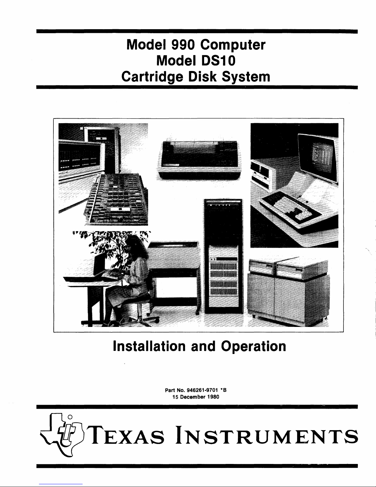
Model 990 Computer
Model
DS10
Cartridge Disk System
~~~n'"'
<.~
Installation and Operation
Part No. 946261-9701 * B
15 December
1980
TEXAS
INSTRUMENTS
Page 2
© Texas Instruments Incorporated 1977, 1978, 1979, 1980
All Rights Reserved, Printed in U.S.A.
The
information
and/or
drawings
set
forth
in
this
document
and all
rights
in and
to
inventions
disclosed
herein and
patents
which
might
be granted thereon
disclosing
or
employing
the materials,
methods,
techniques
or apparatus
described
herein, are the
exclusive
property
of
Texas
Instruments
Incorporated.
MANUAL REVISION HISTORY
Model 990 Computer Model DS10 Cartridge Disk System
Installation
and Operation (946261-9701
*8)
Original Issue
..................................
. 1 December 1977
Change 1
....................................
. 15 January 1978 (ECN 419819)
Change 2
....................................
. 15 August 1978 (ECN 437233)
Change 3
.....................................
15 March 1979 (ECN 449602)
Change 4
....................................
. 15 August 1980 (MCR 000297)
Revision .
......................................
. 15 December 1980 (MCR 000440)
I The total number
of
pages in this publication
is
126.
I
I
I
l
________________________
J
Page 3

"i1"
946261-9701
~-------
PREFACE
This manual provides detailed instructions for installing a Texas Instruments Model DSIO
Cartridge Disk System in conjunction with a properly installed Model 990 Computer. In addition,
it
contains information required
description
information
Section
1 General Description - This section briefly describes the features and major com-
of
the disk system with specific attention to the controls and indicators. The
is divided
ponents
of
into
the
the
disk system
to
program the computer
following sections:
to
acquaint the reader with the system.
to
use the disk system and a
2 Installation -
ing
a Model DSIO Cartridge Disk System. Information is also provided
the site for the installation
The procedures given in
digital electronics.
3
Programming
in
designing a service routine
4
Operation - This section describes
disk system operators, and describes the use
operation
Model 990/5 Computer System Hardware User's Manual
Model
Model
Model
Depot Maintenance Manual
This section contains step-by-step procedures for unpacking and install-
is properly prepared prior
this section presuppose
~
This section presents interfacing information for use
to
control the disk system's activity.
of
the
disk system.
Title
990/10 Computer System Hardware Reference Manual
990/12 Computer Hardware User's Manual
990 Computer Model DSIO Cartridge Disk System
to
that
the
controls and indicators
of
those controls and indicators in the
installation
the reader
of
Part Number
946294-9701
945417
2264446-9701
946262-9701
to
ensure that
of
the disk system.
is
not
familiar with
by
a programmer
the
disk system for
-9701
Model
Model
Language Programmer's Guide
990 Computer Programming Card
990 Computer TMS 9900 Microprocessor Assembly
iii/iv
943440-9701
943441-9701
Digital Systems Division
Page 4

Page 5
~-------
'iY
946261-9701
TABLE
OF
CONTENTS
Pangrapb
Title Page
SECTION 1.
GENERAL
DESCRIPTION
1.1 General
.....................................................................
-
...
1-1
1.2 System Configuration
............................................................
1-1
1.2.1
TILINE
Bus
....... ' ...........................................................
1-2
1.2.2 Disk Controller
...............................................................
1-5
1.2.3 Disk Drives
..................................................................
1-5
1.3 System Operation
...............................................................
1-6
1.4 System Specifications
...........................................................
1-10
2.1
2.2
2.2.1
2.2.2
2.2.3
2.2.4
2.2.5
2.2.6
2.3
2.3.1
2.3.2
2.3.3
2.3.4
2.3.5
2.3.5.1
2.3.5.2
2.3.5.3
2.3.6
2.4
2.4.1
2.4.2
2.4.3
2.4.3.1
2.4.3.2
2.4.3.3
2.4.3.4
2.4.4
2.4.4.1
2.4.5
2.4.6
2.4.7
2.4.8
2.4.8.1
2.4.8.2
SECTION 2.
INSTALLATION
General
........................................................................
2-1
Site Requirements
...............................................................
2-2
Mounting
Space Requirements for Rack
Mount
Disk Drive
..........................
2-2
Mounting
Space Requirements for Cabinet
Mount
Disk Drive
........................
2-2
Ac Power Requirements
........................................................
2-5
Model
990
Computer
..........................................................
2-5
Supportive Environment
.......................................................
2-6
Cabling Restrictions
...........................................................
2-6
Unpacking Instructions
.....................
'
.....................................
2-6
Unpacking Rack
Mount
Disk Drive
..............................................
2-6
Unpacking Disk Controller
....................................................
2-12
Unpacking Cabinet
Mount
Disk Drive
...........................................
2-17
Unpacking Accessories
.. ~ .....................................................
2-21
Unpacking, Handling,
and
Storing Disk Cartridges
................................
2-21
Unpacking Disk Cartridges
..................................................
2-22
Handling Disk Cartridges
...................................................
2-22
Storing Disk Cartridges
.....................................................
2-23
Voltage Conversion Procedures
................................................
2-24
Installation
....................................................................
2-24
Installation
of
Rack
Mount
Disk Drive
..........................................
2-24
Installation
of
Cabinet
Mount
Disk Drive
........................................
2-28
Computer
Chassis
Preparation
for Disk Controller
................................
2-29
Reconfiguring Access
Granted
Circuit
for
New Chassis Slot
(6-
and
13-Slot Chassis)
...................................................
2-29
Reconfiguring Access
Granted
Circuit for New Chassis Slot
(17-Slot
Chassis)
.........................................................
2-34
Interrupt Connections
for 6-and
13-S10t Chassis
................................
2-37
Interrupt Connections
for
17-Slot Chassis
......................................
2-39
Preparation
of
Disk Controller
.................................................
2-42
Selecting Disk
TILINE
Address
..............................................
2-42
Installation
of
Disk Controller
.................................................
2-42
Installing Disk System Interconnection Cables
....................................
2-42
Connection
of
Disk Drive
to
Ac
Power
Source
....................................
2-49
Disk Cartridge Installation
and
Removal
.........................................
2-51
Purging
the
Disk Drive
Air
Filtering System
....................................
2-51
Disk Cartridge Installation
..................................................
2-52
v Digital Systems Division
Page 6
~-------
'iY'
946261-9701
Paragraph
2.4.8.3
2.4.8.4
2.5
3.1
3.2
3.3
3.4
3.4.1
3.4.2
3.4.2.1
3.4.2.2
3.5
3.5.1
3.5.2
3.5.3
3.5.4
3.5.5
3.5.6
3.5.7
3.5.8
3.5.9
3.5.9.1
3.5.9.2
3.5.9.3
3.5.9.4
3.5.9.5
3.5.9.6
3.5.9.7
3.5.9.8
3.6
3.6.1
3.6.2
3.6.2.1
3.6.2.2
3.6.2.3
3.6.2.4
3.6.2.5
3.6.2.6
3.6.2.7
3.6.2.8
TABLE OF CONTENTS (Continued)
Tide
Page
Disk Cartridge Removal
.....................................................
2-56
Removal
of
Disk Cartridge Following Power Failure
or
for Emergency
.............
2-58
System Operational Checkout
....................................................
2-59
SECTION 3. PROGRAMMING
General
........................................................................
3-1
Programming the Disk Controller
.................................................
3-1
Command Control
......................................................
,
.......
3-1
Command Completion
...........................................................
3-1
Command Completion without Interrupts
........................................
3-3
Command Completion with Interrupts
...........................................
3-3
Command Completion Interrupts
..............................................
3-3
Seek and Restore Completion Interrupts
........................................
3-3
Control Words Content and Formats
...............................................
3-3
Disk Status, Control Word 0 ,
...................................................
3-3
Command Control, Control Word 1
.............................................
3-4
Format and Sector, Control Word 2
..............................................
3-5
Cylinders, Control Word 3
.....................................................
3-6
Word Count, Control Word 4
...................................................
3-6
LSB Memory Address, Control Word 5
...........................................
3-7
Unit Select and MSB Memory Address, Control Word 6
.............................
3-7
Interrupt and Controller Status, Control Word 1
...................................
3-8
Disk Commands
.............................................................
3-10
Store
Registers Command
...................................................
3-10
Write Format Command
....................................................
3-10
Read Data Command
.......................................................
3-12
Write Data Command
......................................................
3-13
Read Unformatted Command
................................................
3-14
Unformatted Write Command
...............................................
3-15
Seek Command
............................................................
3-15
Restore Command
.........................................................
3-15
Formats and DefInitions
........................................................
3-16
Definition
of
Terms
..........................................................
3-16
Sector Format
...............................................................
3-16
Gap 1
....................................................................
3-11
Synchronization (Sync) Character
............................................
3-17
Identification (ID) Words
...................................................
3-11
Error Detection Code (EDC) Number 1
........................................
3-18
Gap2
.....................................................................
3-18
Data
.....................................................................
3-18
Error Detection Code (EDC) Number 2
........................................
3-18
Gap 3
....................................................................
3-18
SECTION 4. OPERATION
4.1 General
........................................................................
4-1
4.2 Controls and Indicators
..........................................................
4-1
4.2.1 Ac Circuit ·Breaker
............................................................
4-1
vi
Digital Systems Division
Page 7
~-------
~
946261-9701
Paragraph
4.2.2
4.2.3
4.2.4
4.2.5
4.2.6
4.2.7
4.2.8
4.2.9
4.3
4.3.1
4.3.2
4.3.3
4.3.3.1
4.3.3.2
4.3.3.3
4.3.4
4.3.5
4.3.6
4.3.7
4.3.8
4.4
4.5
4.5.1
4.5.2
4.5.3
4.5.3.1
4.5.3.2
Table
TABLE OF CONTENTS (Continued)
Title
Page
Dc Circuit Breaker
............................................................
4-1
START/STOP
Switch/Indicator
...............................................
.4-1
READY Indicator
.............................................................
4-2
ACTIVE
Indicator
............................................................
4-2
F
AUL T /RESET
Indicator/Switch
...............................................
4-2
WRITE/PROTECT
CART
Indicator/Switch
....................................
.4-3
WRITE/PROTECT
FIXED
Indicator/Switch
.....................................
4-3
BRU~H
Indicator
.............................................................
4-3
Operating Instructions
...........................................................
4-3
Operating Precautions
.........................................................
4-3
Power Application for Online Operation
..........................................
4-4
Disk Cartridge Installation
and
Removal
..........................................
4-4
Disk Cartridge Installation
...................................................
4-4
Disk Cartridge Removal
......................................................
4-5
Removal
of
Disk Cartridge Following Power Failure
or
for
Emergency
..............
4-6
Write
Protect
.................................................................
4-6
Stop
and
Power
Removal
.......................................................
4-6
Changing Disk Assignments
....................................................
4-7
Fault
Operating Procedures
.....................................................
4-7
Operator
Preventive Maintenance
...............................................
4-7
Maintenance Aids
...............................................................
4-7
Preventive Maintenance
.....................
~
...................................
4-11
Preventive Maintenance
for
the
Rack
Mount
Disk Drive
............................
4-11
Preventive Maintenance
for
the
Cabinet
Mount
Disk Drive
.........................
4-11
Preventive Maintenance
for
the
Cartridge Disk
...................................
4-12
General
...........................................
'
........................
4-12
Maintenance Procedures
....................................................
4-13
LIST OF ILLUSTRATIONS
TItle Page
1-1
Model
DSI0
Cartridge Disk System
................................................
1-0
1-2 Model
DSI0
Cartridge Disk
Unit
Subsystem Simplified Diagram
.......................
1-2
1-3
TILINE
Master-to-Slave Write Cycle Timing
........................................
1-3
1-4
TILINE
Master-to-Slave
Read
Cycle Timing
........................................
1-4
1-5
Interconnection
of
Disk Controller
and
Two Disk Drives
..............................
1-6
1-6 Model
DSI0
Cartridge Disk Controller (PWB)
.......................................
1-7
1-7 Model
DSI0
Cartridge Disk Controller (Fine Line PWB)
..............................
1-8
1-8 Model
DSI0
Cartridge Disk Drive (Cabinet Mount)
...................................
1-9
1-9 Rack
Mount
Disk Drive Physical Dimensions
.......................................
I-II
1-10 Cabinet
Mount
Disk Drive Physical Dimensions
....................................
1-12
2-1
Model
DSI0
Cartridge Disk System Components
.....................................
2-3
2-2 Recommended Rack Dimensions for Model
DSI0
Cartridge Disk Drive
..................
2-4
2-3
Physical Dimensions
of
Cabinet
Mount
Model DSIO Cartridge Disk Drive
...............
2-5
2-4 Rack
Mount
Disk Drive Shipping Configuration
.....................................
2-7
2-5 Cabinet
Mount
Disk Drive Shipping Configuration
...................................
2-8
2-6 Placement
of
Disk Drive for Shipping Bolt Removal
..................................
2-9
vii
Digital Systems Division
Page 8

)175\
______
_
~
946261-9701
LIST OF ILLUSTRATIONS (Continued)
Figure
Title
Page
2-7
Location
of
Electronics Cover Screws
.............................................
2-10
2-8
Carriage Lock Pin Location
.....................................................
2-11
2-9 Card Cage Cover and Clamp Location
.............................................
2-12
2-10 Disk Drive PWB Locations
......................................................
2-13
2-11
Control PWB Switch Settings
....................................................
2-14
2-12 Sector PWB Switch Settings
.....................................................
2-15
2-13
Servo PWB Switch Settings
......................................................
2-16
2-14 Data Recovery PWB Switch Settings
..............................................
2-17
2-15
R/W
/E
PWB Resistor Module Orientation
.........................................
2-18
2-16 Disk Controller Shipping Configuration
...........................................
2-19
2-17
Disk Controller Standard Jumpers
................................................
2-20
2-18
Disk Cartridge
.................................................................
2-23
2-19 Voltage Jumper Plug and Connector
..............................................
2-25
2-20 Rack Slide Assembly Mounting
...................................................
2-27
2-21
Rack Mount Slide Configuration (Right Side Only)
..................................
2-28
2-22 TILINE Access Granted Jumper Locations for
6-S10t
Chassis (Current Production)
......
2-31
2-23
TILINE Access Granted Jumper Locations for
13-S10t
Chassis (Current Production)
.....
2-32
2-24 TILINE Access Granted Jumpers (P2-5 to P2-6) on the Model
990
Backpanel
............
2-33
2-25
Interrupt Plug and TLAG Jumper Switches in the
17-S10t
Chassis
......................
2-35
2-26
17-S10t
Chassis TLAG Jumper Switch Settings
......................................
2-36
2-27
Location
of
Interrupt Jumpers
(6-
and
13-S10t
Chassis)
...............................
2-37
2-28
6-S10t
Chassis Interrupt Jumper Plugs
.............................................
2-39
2-29
13-S10t
Chassis Interrupt Jumper Plugs
............................................
2-40
2-30
17-S10t
Chassis Interrupt Jumper Connector
........................................
2-41
2-31
Model DSI0 Cartridge Disk Controller (PWB)
......................................
2-43
2-32 TILINE Slave Address Switches
..................................................
2-44
2-33
Interconnection Cable Connector Mating
..........................................
2-45
2-34 Interconnection Cable Dressing in Computer Chassis
................................
2-46
2-35
Cable Adapter. , ,
.... , .........................................................
2-47
2-36 Cable Arrangement on Cable Carriers
.............................................
2-48
2-37
XRM (n) Resistor Packs to be Removed from Primary Rack
Mount Disk Drive
I/O
Board
..................................................
2-50
2-38
XRM (n) Resistor Packs to be Removed from Primary Cabinet
Mount Disk Drive
I/O
Board
..................................................
2-50
2-39 Switches and Settings for Rack Mount Primary Disk Drive
............................
2-53
2-40 Switches and Settings for Cabinet Mount Primary Disk Drive
.........................
2-54
2-41
Disk Drive Circuit Breakers
......................................................
2-55
2-42 Brush Indicator
................................................................
2-56
2-43
Disk Cartridge Installation
......................................................
2-57
2-44 Cartridge Locks
................................................................
2-58
3-1
Model DSI0 Disk System Control Word Formats
....................................
3-2
3-2
Control Word 0
.................................................................
3-3
3-3
Control Word 1
.................................................................
3-4
3-4 Control Word 2
.................................................................
3-6
3-5
Control Word 3
.................................................................
3-6
3-6
Control Word 4
.................................................................
3-6
3-7
Control Word 5
.................................................................
3-7
3-8
Control Word 6
.................................................................
3-7
viii
Digital Systems Division
Page 9
~-------
~
946261-9701
LIST OF ILLUSTRATIONS (Continued)
Figure
Title
Page
3-9
Control Word 7
.................................................................
3-8
3-10
Command Format
.............................................................
3-10
3-11
Store Registers Data Format
.....................................................
3-11
3-12
Header Data Format
............................................................
3-12
3-13
Format
of
a Sector Record Bit Stream
.............................................
3-17
4-1
Disk Drive Controls and Indicators
................................................
4-2
4-2
Disk Designation Jumper
.........................................................
4-8
4-3
Disk Controller LEOs (pWB Version)
..............................................
4-9
4-4
Disk Controller LEOs (Fine Line PWB Version)
....................................
4-10
4-5
Disk Contaminants
.............................................................
4-13
LIST
OF
TABLES
Table
nde
Page
1-1
Disk Drive Specifications
........................................................
1-10
1-2
General Characteristics
of
Model OSlO Cartridge Disk System
........................
1-11
1-3
Ac
Power Requirements for Disk Drive (Both
50-
and
6O-Hertz
Drives)
.................
1-13
2-1
Model
OSlO
Cartridge Disk System Components
.....................................
2-2
2-2
Site Environmental Requirements for Model
OSlO
Cartridge Disk System
................
2-6
2-3
Disk Drive Input Voltage Jumper Connections
......................................
2-26
2-4
TILINE Slave Address Switch Settings and Addresses
................................
2-44
3-1
Disk Command Bits
.............................................................
3-5
3-2
Example
of
List Words in a Store Registers Command
...............................
3-11
3-3
Write Format Command
........................................................
3-11
3-4
Example
of
Read Data
..........................................................
3-12
3-5
Read Unformatted Command Example
............................................
3-14
3-6
Example
of a Seek
Command
..................................
~
.................
3-15
ix
Digital Systems Division
Page 10
...-
6
(A)
143663
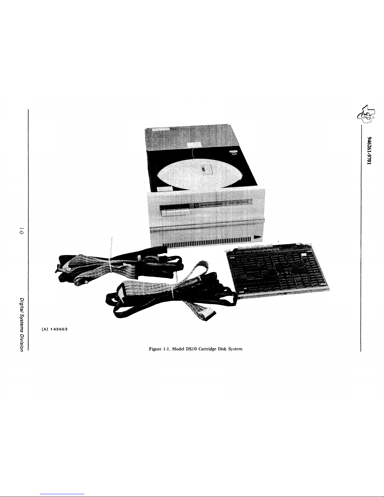
Figure 1-1. Model OSlO Cartridge Disk System
Page 11
Jdls-\
______
_
~
946261-9701
SECTION 1
GENERAL DESCRIPTION
1.1
GENERAL
The Model DSI0 Cartridge Disk System (Figure
1-1)
is
a moving-head random-access magnetic disk
data storage system for the Model
990
Computer. The system consists
of
a printed wiring board disk
controller and up
to
two Model DSI0 Cartridge Disk Drives as shown in Figure 1-2. A Model DSI0
Cartridge Disk System consisting
of
one disk controller and two disk drives
is
capable
of
storing
25.2 million unformatted bytes
of
data, 12.6 million per disk drive (20 million,
10
million per disk
drive, when formatted).
The disk system features include:
•
•
•
•
•
•
•
Single printed wiring board controller capable
of
supporting two disk drives.
Transfer rate
of
312K bytes per second
A fixed and a removable disk
Automatic track switching across head and cylinder boundaries
Variable record formats, from one sector to full track
Efficient disk formatting and double-frequency recording for high percentage use
of
storage
Controller self-diagnostic capability
The Model
DSI0 Cartridge Disk System uses a magnetic medium-density (2200 bits per inch) disk
(one fixed, one removable) and flying heads that move laterally over the disk surfaces
to
select dif-
ferent cylinders. Control for up
to
two disk drives resides
on
a disk controller printed wiring board
(PWB) located in a Model 990 Computer chassis. The controller uses
an
on-board microprocessor
to
handle all time-critical events in the transfer
of
data between the computer and the disk drive. The
disk drive assembly includes the mechanical, e1etromechanical, and electronic components required
to rotate the disks, perform track selection, and read and write data on the disk.
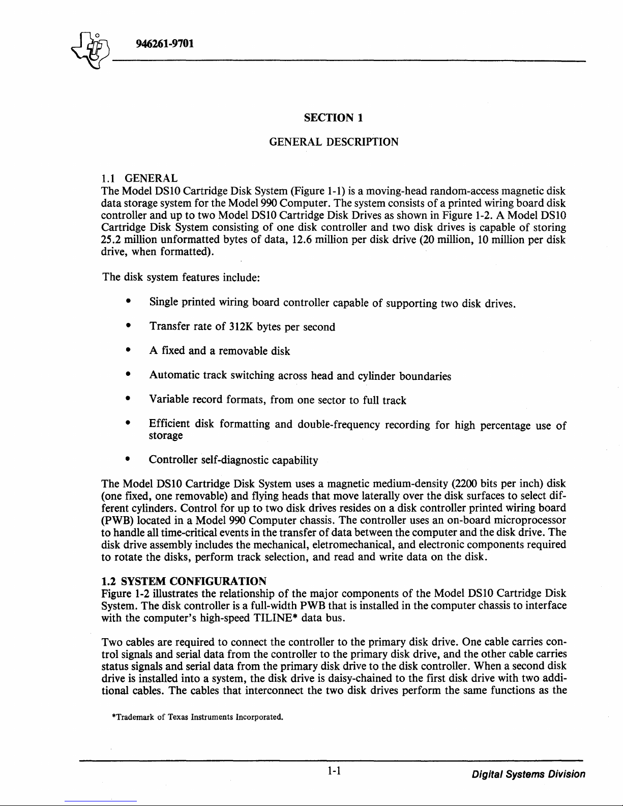
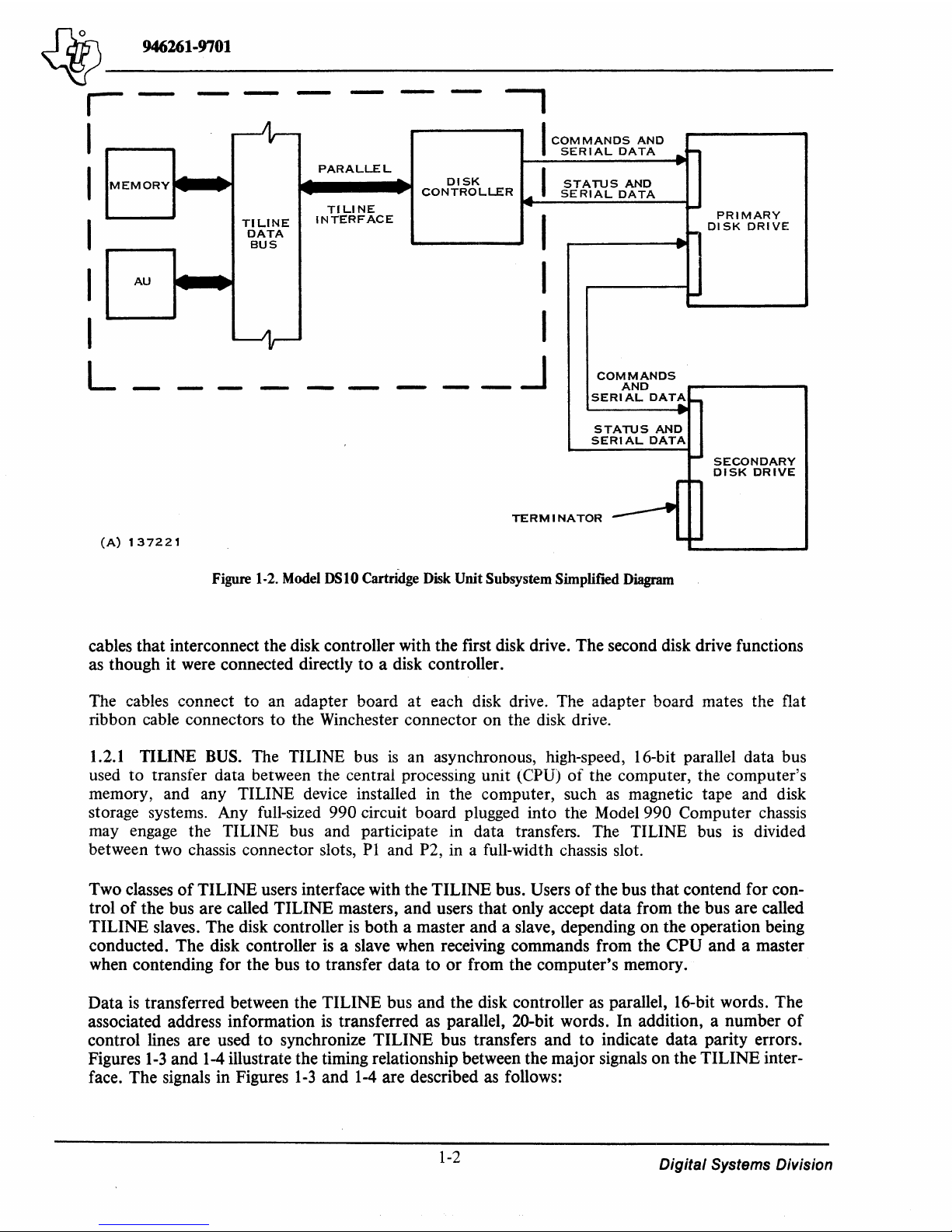
1.2
SYSTEM CONFIGURATION
Figure
1-2
illustrates the relationship
of
the major components
of
the Model DSI0 Cartridge Disk
System. The disk controller
is
a full-width PWB that
is
installed in the computer chassis to interface
with the computer's high-speed TILINE* data bus.
Two cables are required
to
connect the controller
to
the primary disk drive. One cable carries control signals and serial data from the controller to the primary disk drive, and the other cable carries
status signals and serial data from the primary disk drive
to
the disk controller. When a second disk
drive
is
installed into a system, the disk drive
is
daisy-chained to the first disk drive with two addi-
tional cables. The cables that interconnect the two disk drives perform the same functions as the
*Trademark
of
Texas Instruments Incorporated.
1-1
Digital Systems Division
Page 12
~-------
~
946261·9701
r
I
---
---
I
MEMORY
I
I
I
L
AU
-
~
--
~
-
A)
137221
I
COM
MANOS
AND
SERIAL
DATA
..
-
PARALLEL
~
I
..
DISK
STATUS
AND
CONTROLLER
SERIAL
DATA
TILINE
...
I-
INTERFACE
I
PRIMARY
TILINE
DISK
DRIVE
DATA
..
~
BUS
...
I
--
-
~
I
_J
COMMANDS
-
-
-
-
-
-
AND
SERIAL
DAT~_
...
STATUS
AND
SERIAL
DATA
-
SECONDARY
DISK
DRIVE
~-
TERM I NA
TOR
------"
-I-
Figure
1-2.
Model
OSlO Cartridge
Disk
Unit Subsystem Simplifred
Diagram
cables that interconnect the disk controller with the first disk drive. The second disk drive functions
as though it were connected directly to a disk controller.
The cables connect to
an
adapter board at each disk drive. The adapter board mates the flat
ribbon cable connectors to the Winchester connector on the disk drive.
1.2.1 TILINE
BUS.
The TILINE bus
is
an
asynchronous, high-speed, 16-bit parallel data bus
used to transfer data between the central processing unit
(CPU) of the computer, the computer's
memory, and any TILINE device installed in the computer, such
as
magnetic tape and disk
storage systems. Any full-sized
990 circuit board plugged into the Model 990 Computer chassis
may engage the TILINE bus and participate in data transfers. The TILINE bus
is
divided
between two chassis connector slots, PI and P2, in a full-width chassis slot.
Two classes
of
TILINE users interface with the TILINE bus. Users
of
the bus that contend for con-
trol
of
the bus are called TILINE masters, and users that only accept data from the bus are called
TILINE slaves. The disk controller
is
both a master and a slave, depending on the operation being
conducted. The disk controller
is
a slave when receiving commands from the CPU and a master
when contending for the bus to transfer data to or from the computer's memory.
Data
is
transferred between the TILINE bus and the disk controller as parallel, 16-bit words. The
associated address information
is
transferred as parallel, 20-bit words. In addition, a number
of
control lines are used to synchronize TILINE bus transfers and to indicate data parity errors.
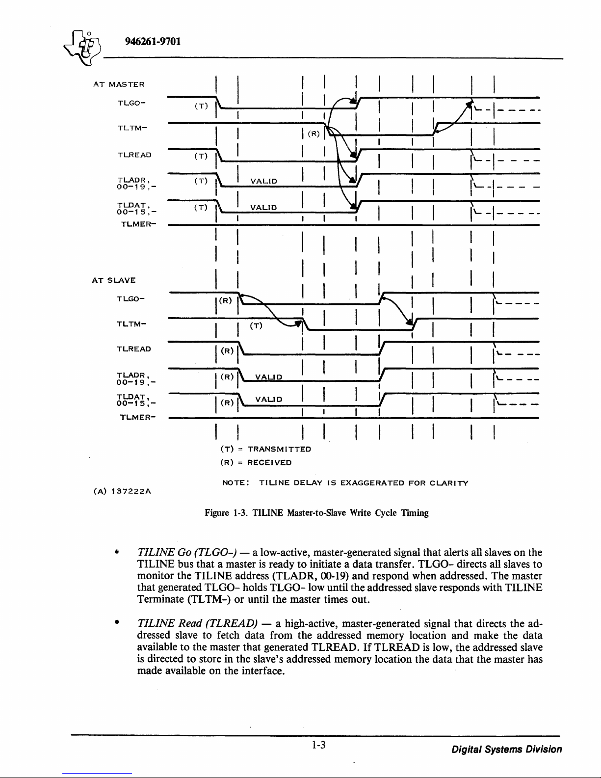
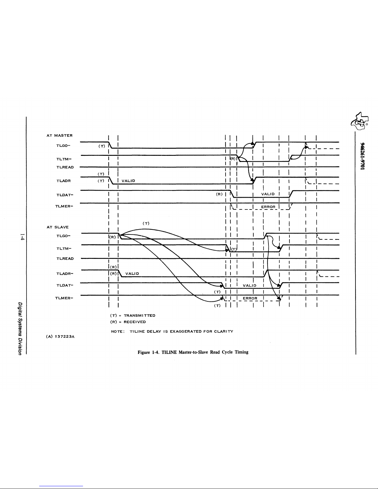
Figures
1-3
and
1-4
illustrate the timing relationship between the major signals on the TILINE inter-
face. The signals in Figures
1-3
and
1-4
are described as follows:
1-2
Digital Systems Division
Page 13
~-------
~
946261-9701
AT
MASTER
TLGO-
TLTM-
TLREAD
TLADR,
00-19,-
TLDAT,
00-15,-
TLMER-
AT
SLAVE
TLGO-
TLTM-
TLREAD
TLADR,
00-19,-
TLDAT,
00-15,-
TLMER-
(A)
137222A
(
T)
I
I
I
(R)
I
(T)
I
I
(T)
VALID
I
I
I
I
~
(T)
I'
VALID
I
I
I
I
I
\
I
I
,
I
I
I
I
I
I
I I
I
\(R)
~
~
I
S
I
I
I
I
(T)
9'
I
I
Y
I
1
(R)
~
I
I
,
I
Y
I
(R)
I'
VALID
I
I
I
I
I
(R)
I'
VALID
Y
I
I
I
I
I
I
I
(T) = TRANSMITTED
(R) = RECEI
VED
NOTE:
TILINE
DELAY
IS
EXAGGERATED
FOR
CLARITY
Figure 1-3. TILINE Master-to-Slave Write Cycle Timing
I
I
L-I-----
I
I
1'--
-I-
IL--I---
-
I
I
\
1'--
-1-
----
I
I
I
\
I~
----
I
\
\\.-
---
f'---
--
X
1\--- -
•
TILINE
Go (TLGO-) - a low-active, master-generated signal that alerts all slaves on the
TILINE bus that a master
is
ready to initiate a data transfer.
TLGO-
directs all slaves to
monitor the TILINE address (TLADR, 00-19) and respond when addressed. The master
that generated
TLGO- holds
TLGO-
low until the addressed slave responds with TILINE
Terminate (TL TM-) or until the master times out.
• TILINE Read (TLREAD) - a high-active, master-generated signal that directs the ad-
dressed slave to fetch data from the addressed memory location and make the data
available to the master that generated TLREAD.
If
TLREAD
is
low, the addressed slave
is
directed to store in the slave's addressed memory location the data that the master has
made available on the interface.
1-3
Digital Systems Division
Page 14
AT
MASTER
TLGO-
TLTMTLREAD
TLADR
TLDAT-
TLMER-
AT
SLAVE
-
TLGO-
I
.J:>..
TLTM-
TLREAD
TLADR-
TLDAT-
TLMER-
0
cO'
::;:
Q)
-
(I)
~
CD
3
en
(A)
137223A
0
~.
~.
O·
:::s
(T)
(T)
(T)
VALID
~R)
1
I I
I I
I
,'-J
___
_
I I I
--------------------------------------------(-R-)~~~
_________
VA_L_I_D~--~Vr----
----------
I I
(R)
I I
I I
I I
I(R)
VALID
1 1
(T)
(T) = TRANSMI
TTED
(R)
::
RECEI
VED
K 1
ERROR
I;
'-
_________
...:1
I
1
I
I
I
VALID
ERROR
,
- - - -
-1--
NOTE:
TILINE
DELAY
IS
EXAGGERATED
FOR
CLARITY
Figure 1-4. TILINE Master-to-Slave Read Cycle Timing
1'----
1'----
Page 15
~
946261-9701
~~------------------
TILINE
•
master that generated
memory write or that the slave's memory data
(TLDAT, 00-15). The slave that generated
removes
TILINE
•
dress the slave memory location to be accessed for the read or write operation.
TILLVE Data
provide two-way data transfer over the TILINE interface.
TILINE
•
the master that the active slave detected a parity error when data was fetched from the
slave's memory. The slave performs no parity check on data fetched from its registers.
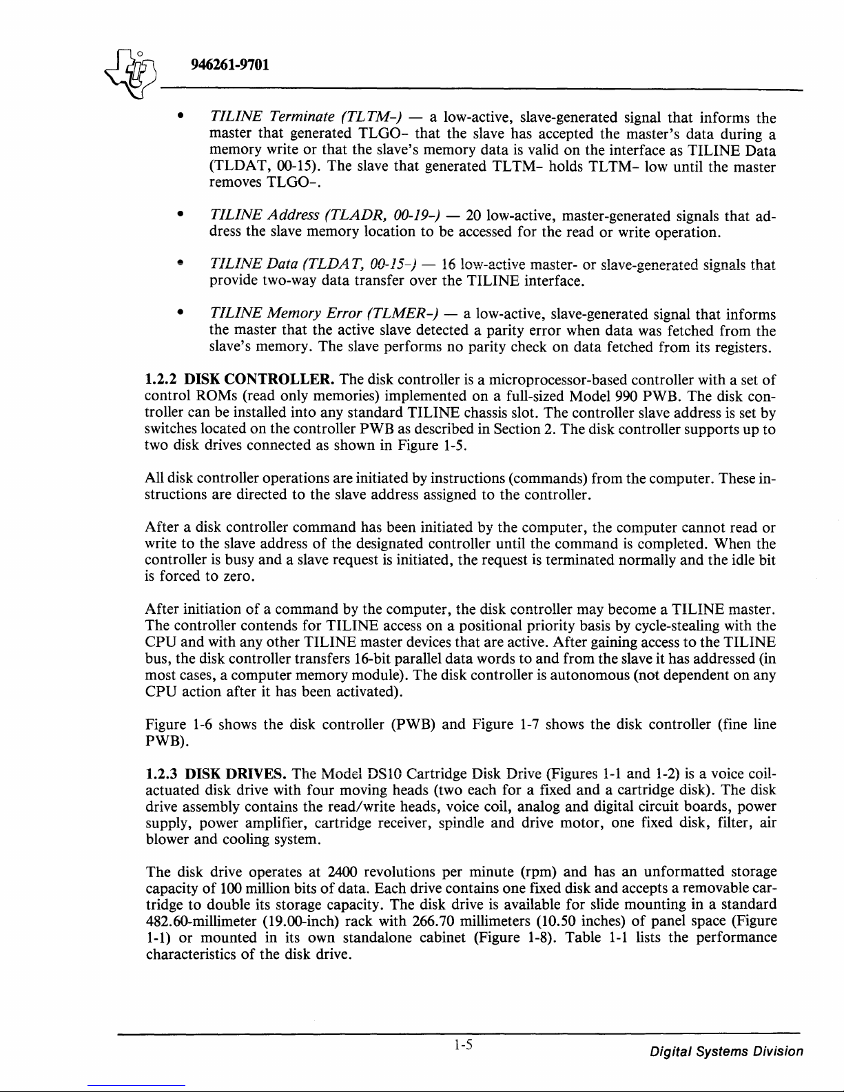
1.2.2
DISK CONTROLLER. The disk controller
control ROMs (read only memories) implemented on a full-sized Model 990 PWB. The disk controller can be installed into any standard TILINE chassis slot. The controller slave address
switches located on the controller
two disk drives connected
All disk controller operations are initiated by instructions (commands) from the computer. These instructions are directed to the slave address assigned to the controller.
Terminate
TLGO-.
Address
Memory Error
(TLTM-)
(TLADR,
(TLDAT,
as
shown in Figure
- a low-active, slave-generated signal that informs the
TLGO-
00-19-) -
00-15-) -
(TLMER-)
PWB
as
that the slave has accepted the master's data during a
is
valid on the interface
TLTM-
20
low-active, master-generated signals that ad-
16
low-active master- or slave-generated signals that
- a low-active, slave-generated signal that informs
is
a microprocessor-based controller with a set
described in Section
1-5.
holds
TLTM-
2.
The disk controller supports up to
as
TILINE Data
low until the master
of
is
set by
After a disk controller command has been initiated by the computer, the computer cannot read or
write to the slave address
controller
is
forced to zero.
After initiation
The controller contends for TILINE access on a positional priority basis by cycle-stealing with the
CPU and with any other TILINE master devices that are active. After gaining access to the TILINE
bus, the disk controller transfers 16-bit parallel data words to and from the slave it has addressed (in
most cases, a computer memory module). The disk controller
CPU action after it has been activated).
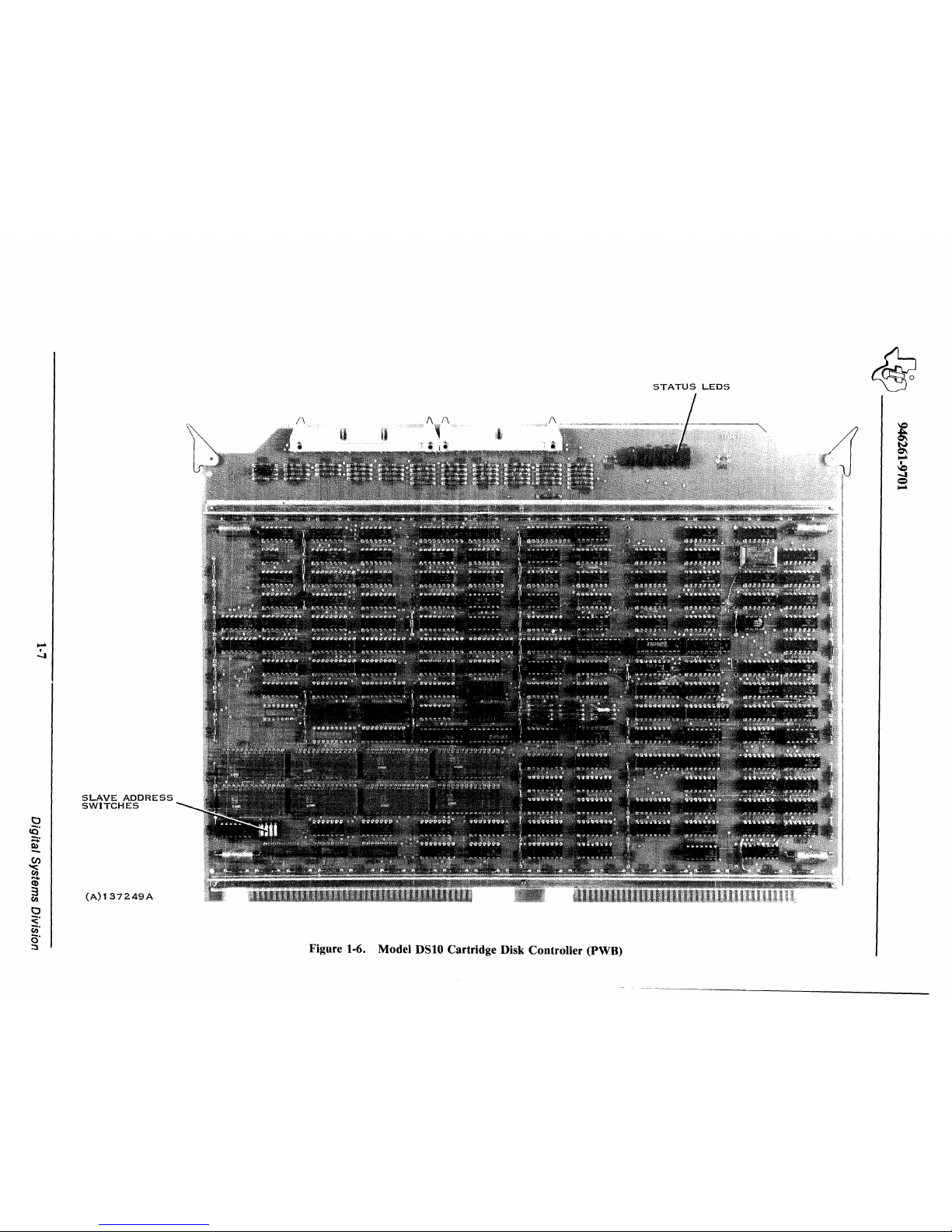
Figure
PWB).
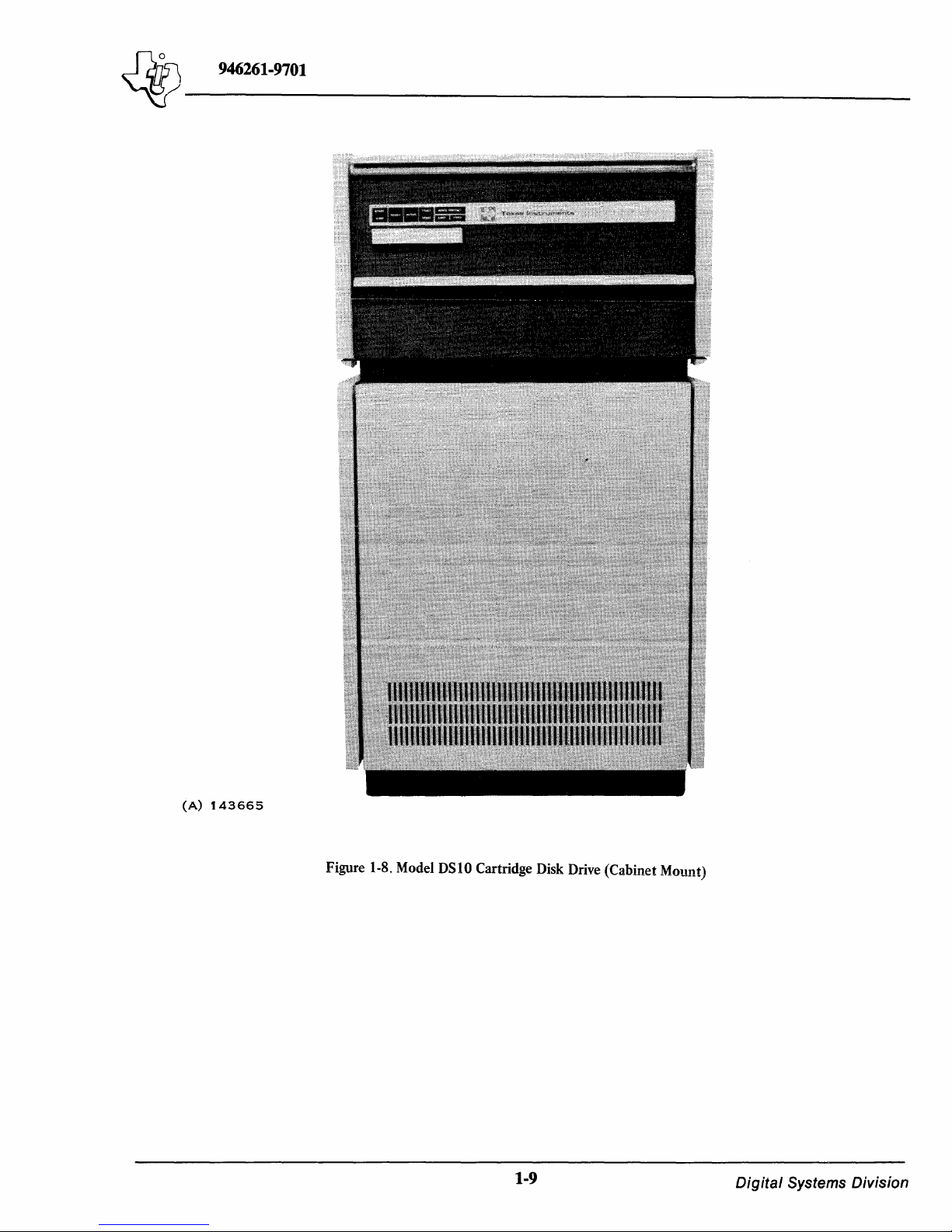
1.2.3 DISK DRIVES. The Model
actuated disk drive with four moving heads (two each for a fixed and a cartridge disk). The disk
drive assembly contains the read/write heads, voice coil, analog and digital circuit boards, power
supply, power amplifier, cartridge receiver, spindle and drive motor, one fixed disk, filter, air
blower and cooling system.
The disk drive operates at 2400 revolutions per minute (rpm) and has an unformatted storage
capacity
tridge to double its storage capacity. The disk drive
482.60-millimeter (19.00-inch) rack with 266.70 millimeters
1-1)
characteristics
is
busy and a slave request
of
a command by the computer, the disk controller may become a TILINE master.
1-6
shows the disk controller (PWB) and Figure
of
100
million bits
or
mounted in its own standalone cabinet (Figure 1-8). Table
of
the disk drive.
of
the designated controller until the command
is
initiated, the request
DSIO
Cartridge Disk Drive (Figures
of
data. Each drive contains one fixed disk and accepts a removable car-
is
is
terminated normally and the idle bit
is
autonomous (not dependent on any
1-7
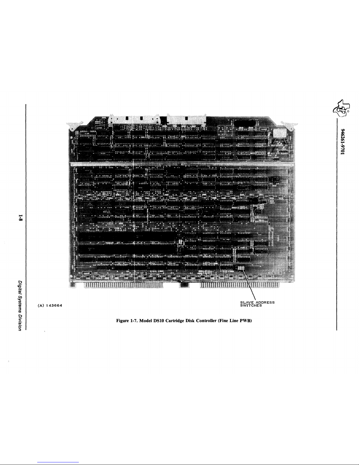
shows the disk controller (fine line
available for slide mounting in a standard
(10.50 inches)
is
completed. When the
1-1
and
1-2)
is
a voice coil-
of
panel space (Figure
1-1
lists the performance
1-5
Digital
Systems Division
Page 16
~~------------------
~
946261-9701
50-WIRE
CABLE
937516-0001
-
CABINET
MOUNT
937516-0003
-
RACK
MOUNT
40-WIRE
CABLE
937515-0001
-
CABINET
MOUNT
937515-0003
-
RACK
MOUNT
~--~---~{--------~
6.1
M
(20
FT)
CABLE
(CABINET
MOUNT)
3.05
M
(10FT)
CABLE
(RACK
MOUNT)
CABLE
ADAPTER
,.83
M
(6
FT)
DAISY
CHAIN
CABLES
(A)142127A
CABLE
ADAPTER
937510-0001
P3
P4
DISK
CONTROLLER
ASSEMBLY
(COMPONENT
SIDE)
PI
937505-0001
2262100-0001
P2
NOTES:
1.
WHEN
ONLY
ONE
DISK
DRIVE
IS
USED
THE
TERMINATING
RESISTORS
ARE
LOCATED
ON
THE
PRIMARY
DISK
DRIVE.
2.
STANDARD
CONFIGURATION.
PRIMARY
DISK
DRIVE
(LOGICAL
UNIT
O-FIXED
LOGICAL
UNIT
1-REMOVABLE)2
937513-0001
(RACK
MOUNT)
937513-0005
(CABINET
MOUNT)
SECONDARY
DISK
DRIVE
(LOGICAL
UNIT
2-FIXED
LOGI
CAL
UNI T 3-REMOVABLE)2
TERMINATING
RESISTORS
1
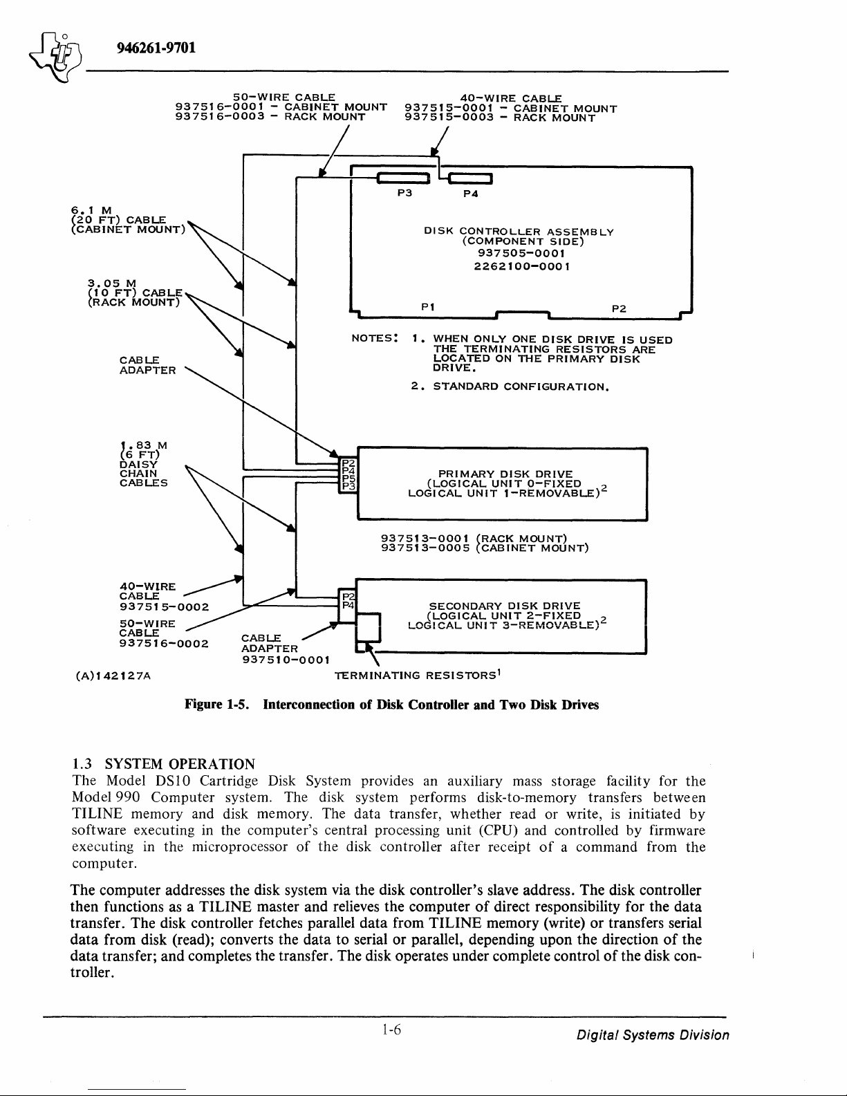
Figure 1-5. Interconnection of Disk Controller and Two Disk Drives
1.3 SYSTEM
OPERATION
The
Model DS 10 Cartridge Disk System provides an auxiliary mass storage facility for
the
Model990
Computer
system. The disk system performs disk-to-memory transfers
between
TILINE
memory
and disk memory. The
data
transfer,
whether
read
or
write,
is
initiated
by
software executing in
the
computer's
central processing
unit
(CPU) and controlled
by
firmware
executing
in
the
microprocessor
of
the
disk controller
after
receipt
of a command
from
the
computer.
The computer addresses the disk system via the disk controller's slave address. The disk controller
then functions as a TILINE master and relieves the computer
of
direct responsibility for the data
transfer. The disk controller fetches parallel data from TILINE memory (write) or transfers serial
data
from disk (read); converts the data to serial or parallel, depending upon the direction
of
the
data
transfer; and completes the transfer. The disk operates under complete control
of
the disk con-
troller.
1-6
Digital
Systems Division
Page 17
SLAVE
ADDRESS
SWITCHES
(A)137249A
STATUS
LEOS
Figure 1-6. Model DSI0 Cartridge Disk Controller (PWB)
Page 18
~
I
QO
(A)
143664
SLAVE
ADDRESS
SWITCHES
Figure 1-7. Model
DSI0
Cartridge Disk Controller (Fine Line PWB)
Page 19
"'ij/
Jd7)\
______
946261-9701
_
(A)
143665
Figure 1-8. Model OSlO Cartridge Disk Drive (Cabinet Mount)
1-9
Digital
Systems Division
Page 20
~-------
~
946261-9701
Table
I-I.
Disk Drive Specifications
Item
Specificati on
Spindle speed
2400 rpm with
±2%
speed variation with input
frequency
±0.5 hertz and input voltage +10% -
15%
Tracks per surface
Tracks per drive
Tracks per cylinder*
Sectors per drive
Sectors per track
Heads per cylinder*
Heads per drive
Recording surfaces per drive
Recording mode
Track density
Recording density
Bi
ts
per disk drive
Bits per cylinder
Bits per track
Bits per sector
Capacity (unformatted)
Words
per sector
Format overhead
Bit rate
Average access time
Average latency time
Track-to-track access time
Maximum access time
408, numbered 0 through 407
1,632
2
on
each
of
two disks
32,640
20
2
4
4
Double frequency
200 tracks per inch
i 524 bits per inch (outer track)
2200 bits per inch (inner track)
50,000,000 nominal
250,000 nominal
62,500 nominal
3,125
12.6 megabytes
144
48 words
2.5 megahertz
35 milliseconds
12.5 milliseconds
7 milliseconds
60 milliseconds
NOTE: * A cylinder
of
storage consists
of
2 tracks on either
the removable cartridge
or
the fixed disk. The cartridge and
the fixed disk are separate logical units, although they share a
common spindle and a common head carriage; therefore, a
cylinder does not cross disk boundaries.
In a system with one disk controller and two disk drives, the disk controller functions as though only
one disk drive with more storage space were attached. All operations for different disk drives are
identical except for the unit select signal used to identify the drive being addressed.
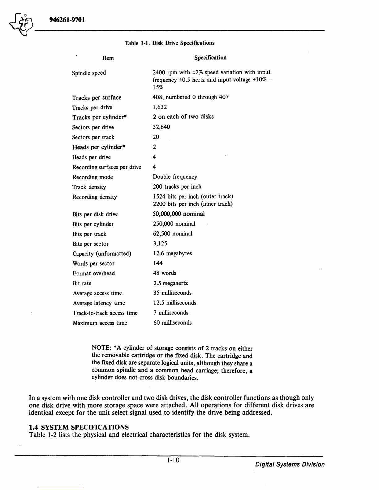
1.4 SYSTEM SPECIFICATIONS
Table
1-2
lists the physical and electrical characteristics for the disk system.
1-10
Digital Systems Division
Page 21
'i:Y
946261-9701
~-------
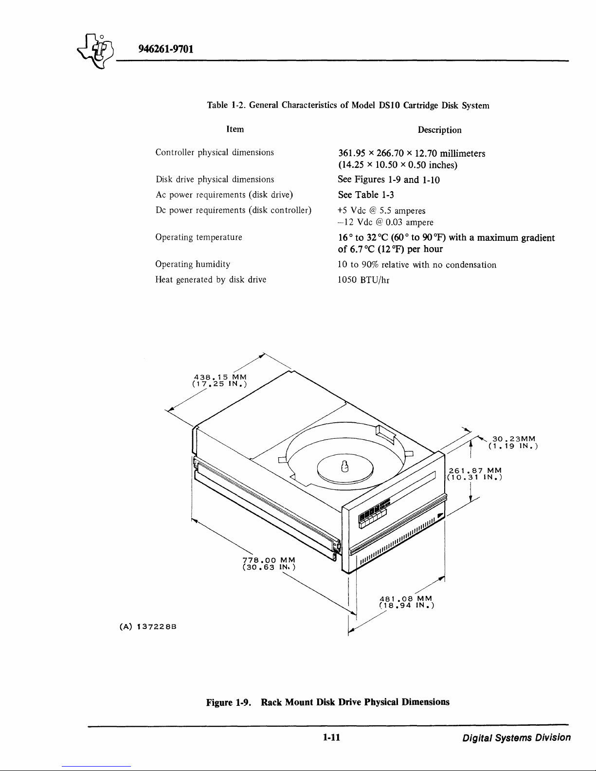
Table 1-2. General Characteristics
Item
Controller physical dimensions
Disk drive physical dimensions
Ac power requirements (disk drive)
Dc power requirements (disk controller)
Operating
Operating
Heat generated
temperature
humidity
by
disk drive
of
Model DSI0 Cartridge Disk System
Description
361.95 x 266.70 x 12.70 millimeters
(14.25 x
See Figures
See
+5
-12
16 ° to
of
10
1050
10.50 x 0.50 inches)
1-9
and 1-10
Table
1-3
V dc @ 5.5 amperes
Vdc
@ 0.03 ampere
32°C (60 °
6.7
°C
(12
to
90% relative
BTU/hr
OF)
to
per
with
90
OF)
with a maximum gradient
hour
no
condensation
(A)
1372288
778.00
(30.63
MM
IN.)
I ,
I
481.08
(18.94
MM
IN.)
V
Figure 1-9. Rack Mount Disk Drive Physical Dimensions
1-11
Digital Systems Division
Page 22
~
946261·9701
~-------
469".90
(18.50
MM---j;(~~~7~51~~;---1
IN.)
457.20MM
~
~~~~~======~~~~~(~'8~.~0~0~IN~·)~111
____
254.00
(10.00
501.65
(19.75
------~
MM
IN.)
31.75
(1.25
MM
IN.)
MM
IN.)
863.60MM
(34.00
IN.)
(A) t 372298
11111111111111
1II111111II1II111111!!!!!111111I1111111
11111111111111
I
76.20
(3.00
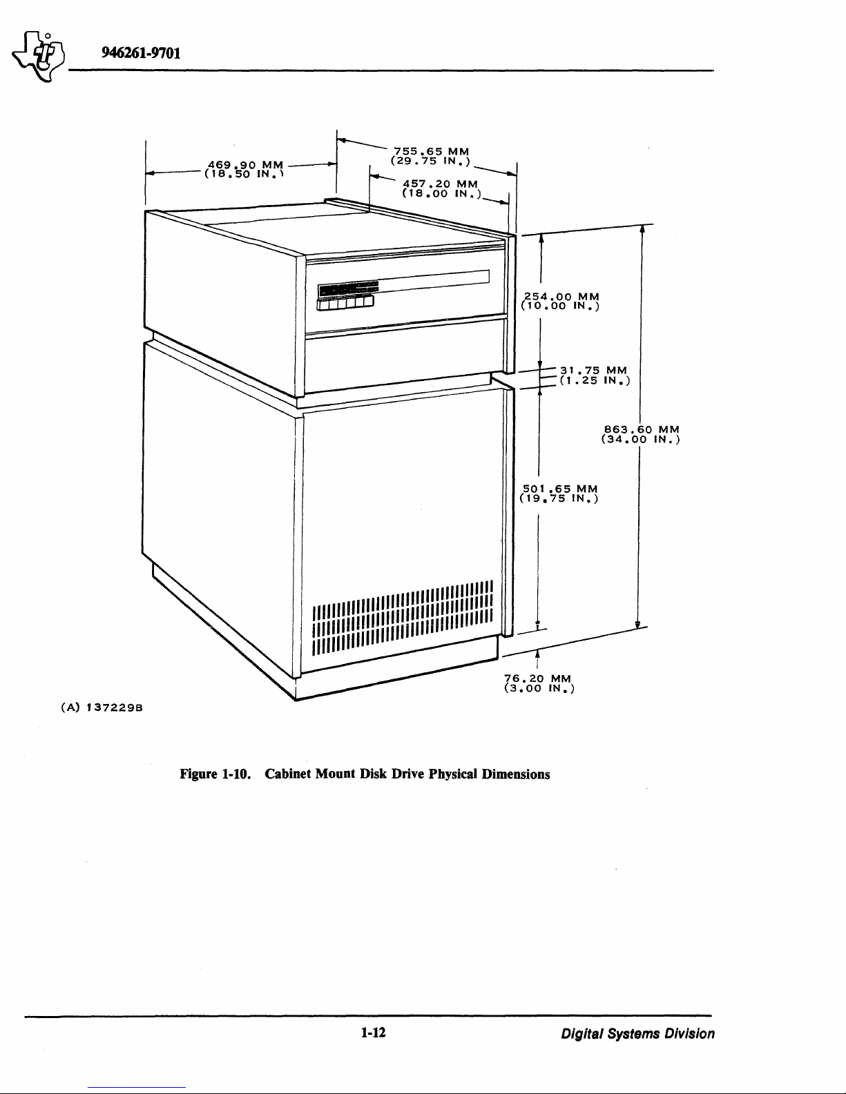
Figure 1-10. Cabinet Mount Disk Drive Physical Dimensions
MM
IN.)
1-12
DlgltaJ Systems Division
Page 23
~
946261-9701
~-------
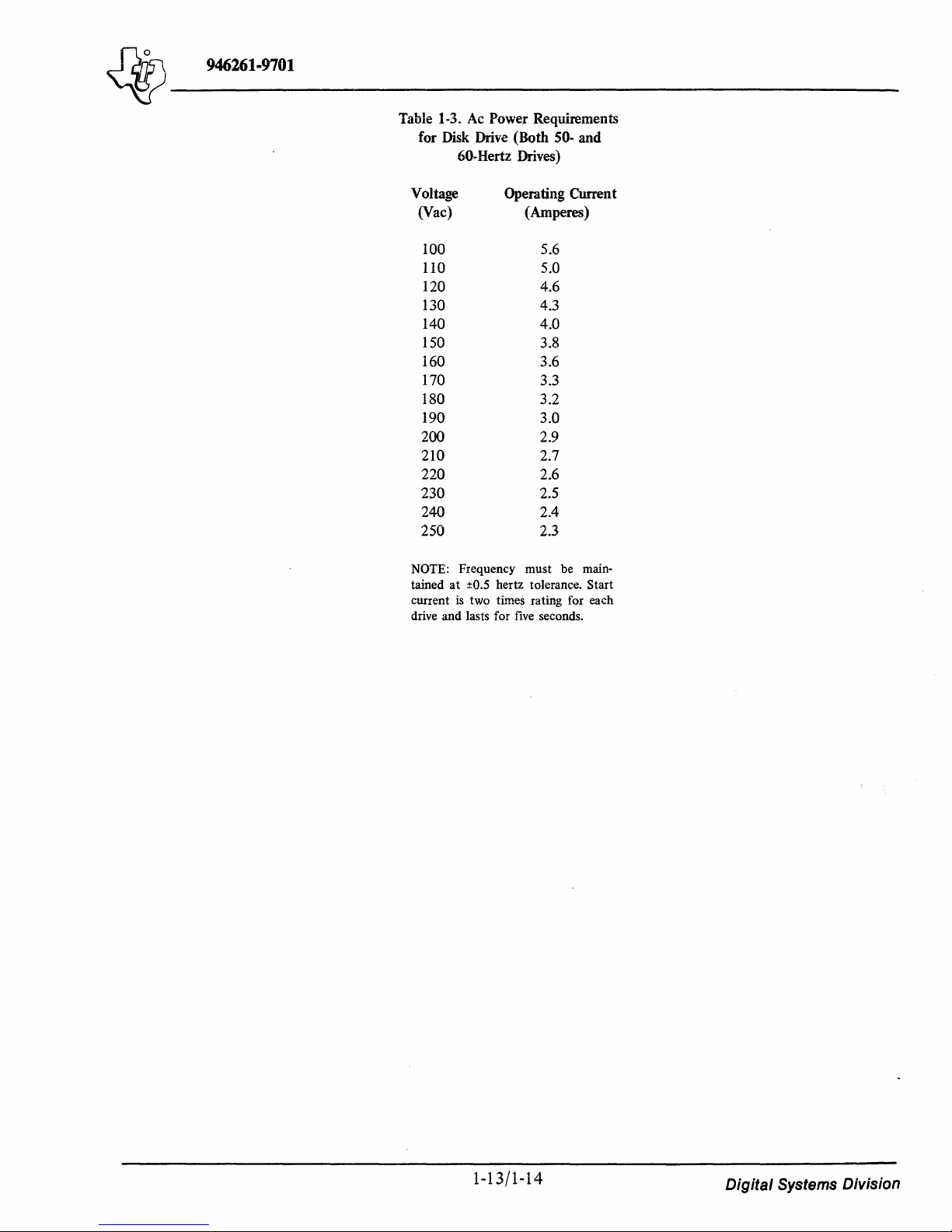
Table 1-3.
for Disk Drive (Both
Voltage Operating Current
(Vac)
NOTE: Frequency must be maintained
current
drive and lasts for
Ac
Power Requirements
60-Hertz Drives)
100
110
120
130
140
150
160
170
180
190
200
210
220
230
240
250
at
:to.S hertz tolerance. Start
is
two times rating for each
50- and
(Amperes)
5.6
5.0
4.6
4.3
4.0
3.8
3.6
3.3
3.2
3.0
2.9
2.7
2.6
2.5
2.4
2.3
five
seconds.
1-13/1-14
Digital Systems Division
Page 24

Page 25
~
946261-9701
~---~---
SECTION 2
INSTALLATION
2.1
GENERAL
This section contains information for unpacking and inspecting a Model
System, and installing the system
provided
the disk system.
The user should read this entire section before proceeding with the installation. Circumstances that
are unique
order from that set forth in this section. Familiarity with the entire installation procedure will pro-
vide a basis for planning the task before starting.
to
ensure that the site for the installation
to
the user's site may dictate that the installation procedures be performed in a different
Do
not connect or disconnect any plug or circuit board when
power
is
applied,
as
a part
as
voltage transients may damage electronic parts.
of
a Model 990 Computer system. Information
is
properly prepared prior
CAUTION
DS
10 Cartridge Disk
to
installation
is
also
of
The expansion guidelines for the disk system allow daisy-chaining two
controller as described in Section
• Complete single-disk drive system - includes disk controller, disk controller-to-disk
drive interface cables, adapter board, and one disk drive
• Disk controller only - includes disk controller and disk controller-to-disk drive interface
cables with adapter board
• Primary disk drive - includes one disk drive
• Secondary disk drive - includes one disk drive, disk drive-to-disk drive interface cables,
and adapter board.
All
of
the above options are available with rack- or cabinet-mount
disk drives for operation
230-volt, 50-hertz operation. Other voltage and frequency options
must be set during installation.
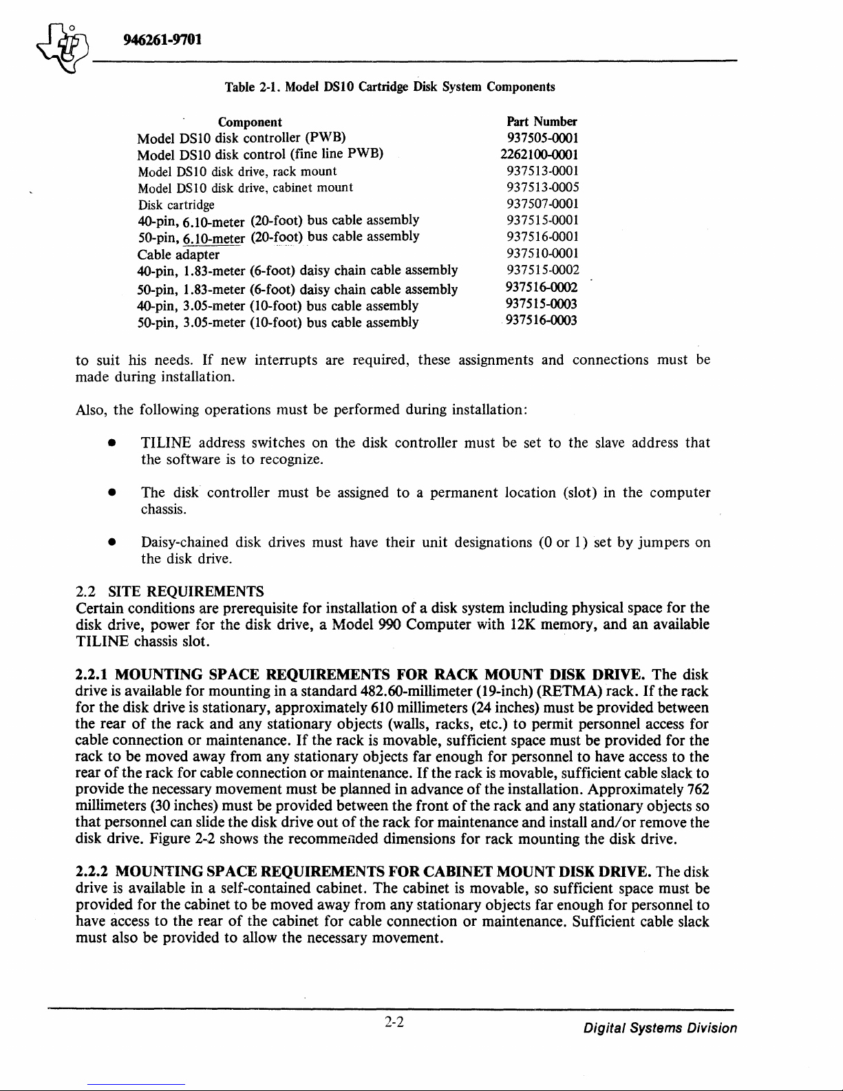
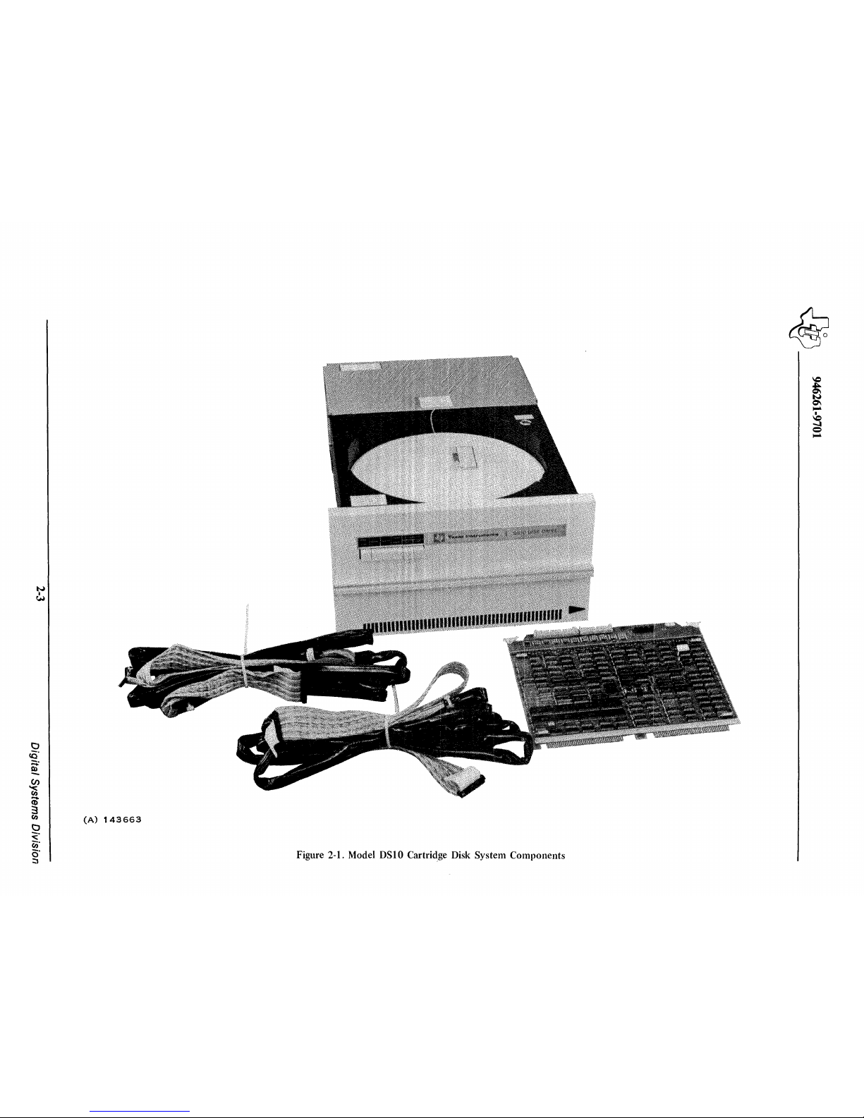
Major system components, along with their associated part numbers, are listed in Table 2-1. Kit
components and additional options, along with the assembly part numbers and purchase price, may
be obtained from Texas Instruments Incorporated upon request. Components
system are shown in Figure 2-1.
1.
Available kit options are:
NOTE
on
110-volt, 6O-hertz and l00-volt
disk drives from one disk
or
of
a typical disk
Interrupt level assignments are required
Computer's TILINE bus. These connections are made at the factory before shipment for a
standard configuration and installation. However,
to
interface the disk controller
if
necessary, the user may assign new interrupts
2-1
to
the Model 990
Digital Systems Division
Page 26
~
946261-9781
~-------
Model
Model
Model
Model
Disk cartridge
4O-pin,
SO-pin,
Cable
4O-pin, 1.83-meter
50-pin,
4O-pin,
50-pin,
DS
DS10 disk
DSI0
DSI0
6.10-meter
6.10-meter
adapter
1.83-meter
3.05-meter
3.05-meter
to suit his needs.
Table 2-1. Model
Component
10 disk
controller
control
disk drive, rack
disk drive, cabinet
(20-foot)
(20-~~-<>t)
(6-foot)
(6-foot)
(10-foot)
(10-foot)
If
new interrupts are required, these assignments and connections must
(PWB)
(fine
mount
bus
bus
daisy
daisy
bus
bus
DSI0
Cartridge Disk System Components
line
PWB)
mount
cable
assembly
cable
assembly
chain
cable
assembly
chain
cable
assembly
cable
assembly
cable
assembly
Part Number
937505-0001
2262100-0001
937513-0001
937513-0005
937507-0001
937515-0001
937516-0001
937510-0001
937515-0002
937516-0002
937515-0003
.937516-0003
made during installation.
Also, the following operations must be performed during installation:
• TILINE address switches on the disk controller must be set to the
the software
is
to recognize.
slave
be
address that
• The disk controller must be assigned to a permanent location (slot) in the computer
chassis.
• Daisy-chained disk drives must have their unit designations (0 or 1) set by jumpers on
the disk drive.
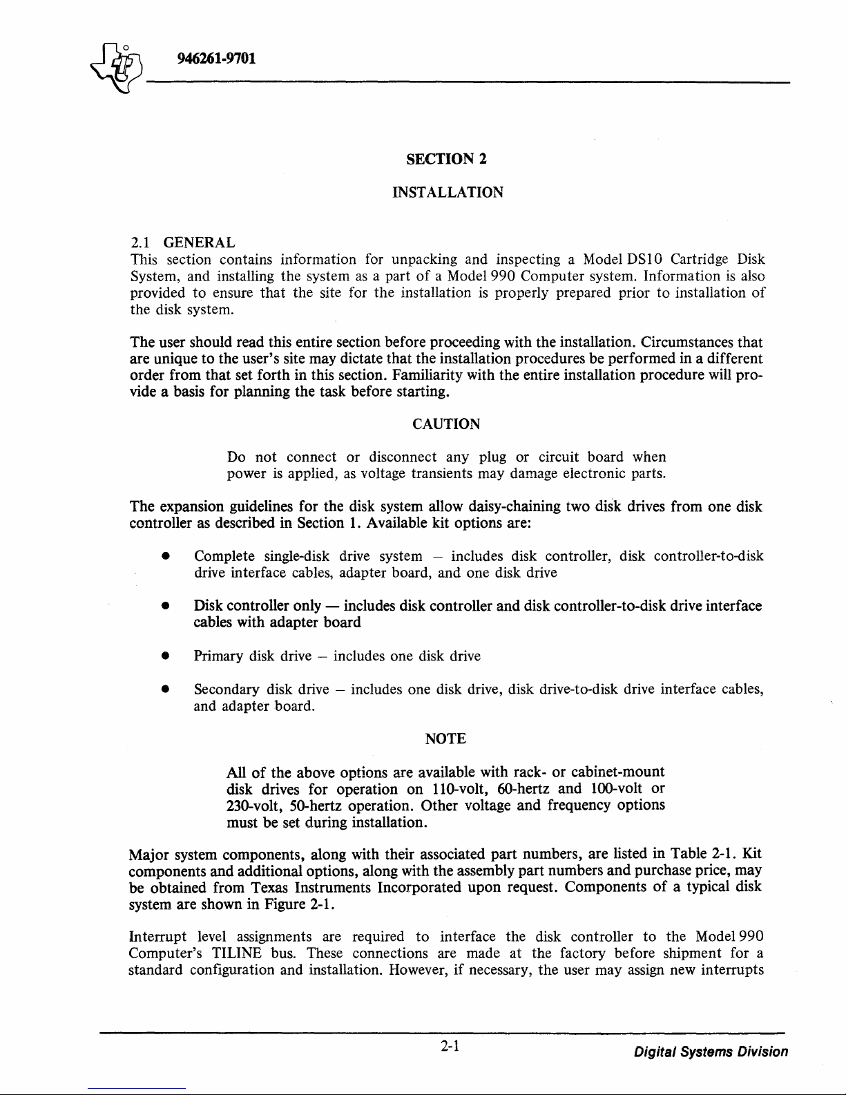
SITE REQUIREMENTS
2.2
Certain conditions are prerequisite for installation
disk drive, power for the disk drive, a Model 990 Computer with
of
a disk system including physical space for the
12K
memory, and
an
available
TILINE chassis slot.
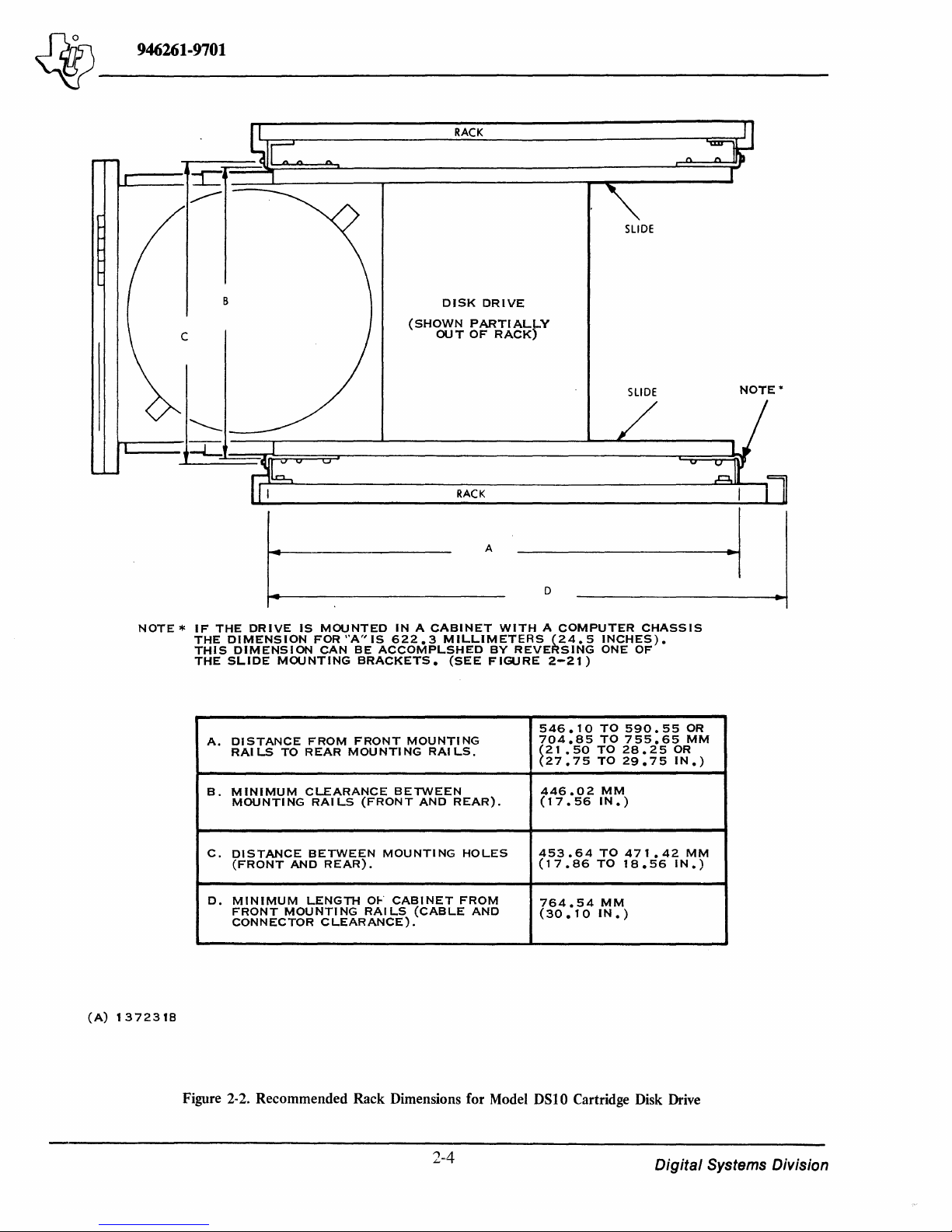
MOUNTING SPACE REQUIREMENTS FOR RACK MOUNT DISK DRIVE. The disk
2.2.1
drive is available for mounting in a standard 482.60-millimeter (19-inch) (RETMA) rack.
for the disk drive
the rear
of
cable connection or maintenance.
rack
to
be moved away from any stationary objects far enough for personnel
rear
of
the rack for cable connection
provide the necessary movement must be planned in advance
millimeters (30 inches) must be provided between the front
that
personnel can slide the disk drive
is
stationary, approximately 610 millimeters (24 inches) must be provided between
the rack and any stationary objects (walls, racks, etc.) to permit personnel access for
If
the rack
or
out
is
movable, sufficient space must be provided for the
maintenance.
of
the rack for maintenance and install
If
the rack
is
movable, sufficient cable slack
of
the installation. Approximately
of
the rack and any stationary objects so
to
have access to the
and/or
If
the rack
remove the
disk drive. Figure 2-2 shows the recommended dimensions for rack mounting the disk drive.
2.2.2
MOUNTING SPACE REQUIREMENTS
drive
is
available in a self-contained cabinet. The cabinet
provided for the cabinet
have access
to
the rear
must also be provided
to
be moved away from any stationary objects far enough for personnel to
of
the cabinet for cable connection
to
allow the necessary movement.
FOR
CABINET MOUNT DISK DRIVE. The disk
is
movable, so sufficient space must be
or
maintenance. Sufficient cable slack
to
762
2-2
Digital
Systems Division
Page 27
N
•
I:H
(A)
143663
Figure 2-1. Model
DSI0
Cartridge Disk System Components
Page 28
~
946261-9701
~-------
RACK
SLIDE
B
DISK
(SHOWN
OUT
DRIVE
PARTIALJ-,Y
OF
RACK)
SLIDE
NOTE
*
~--~-L-==~~~~=u~--------------------------~~~~
RACK
A
~I
D
NOTE * IF
THE
THIS
THE
A.
THE
DRIVE
DIMENSION
DIMENSION
SLIDE
DISTANCE
RAI
MOUNTING
LS
TO
IS
MOUNTED
FOR"A"IS
CAN
FROM
REAR
IN A CABINET
622.3
BE
ACCOMPLSHED
BRACKETS.
FRONT
MOUNTING
MILLIMETERS
(SEE
MOUNTING
RAI
LS.
WITH A COMPUTER
BY
FIGURE
(24.5
REVERSING
2-21)
546.10
704.85
~21
.50
27.75
INCHES).
ONE
OF
TO
590.55
TO
755.65
TO
28.25
TO
29.75
CHASSIS
OR
IN.)
OR
MM
(A)
1372318
MINIMUM
B.
MOUNTING
C.
DISTANCE
(FRONT
MINIMUM
D.
FRONT
CONNECTOR
CLEARANCE
RAILS
BETWEEN
AND
LENGTH
MOUNTING
Figure 2-2. Recommended Rack Dimensions for Model DSIO Cartridge Disk Drive
(FRONT
REAR).
CLEARANCE).
MOUNTI
OF
RAILS
BETWEEN
AND
CABINET
(CABLE
2-4
REAR).
NG
HOLES
FROM
AND
446.02
(17.56
453.64
(17.86
764.54
(30.10
MM
IN.)
TO
TO
MM
IN.)
471.42
18.56
MM
IN.)
Digital
Systems Division
Page 29
~-------
~
946261-9701
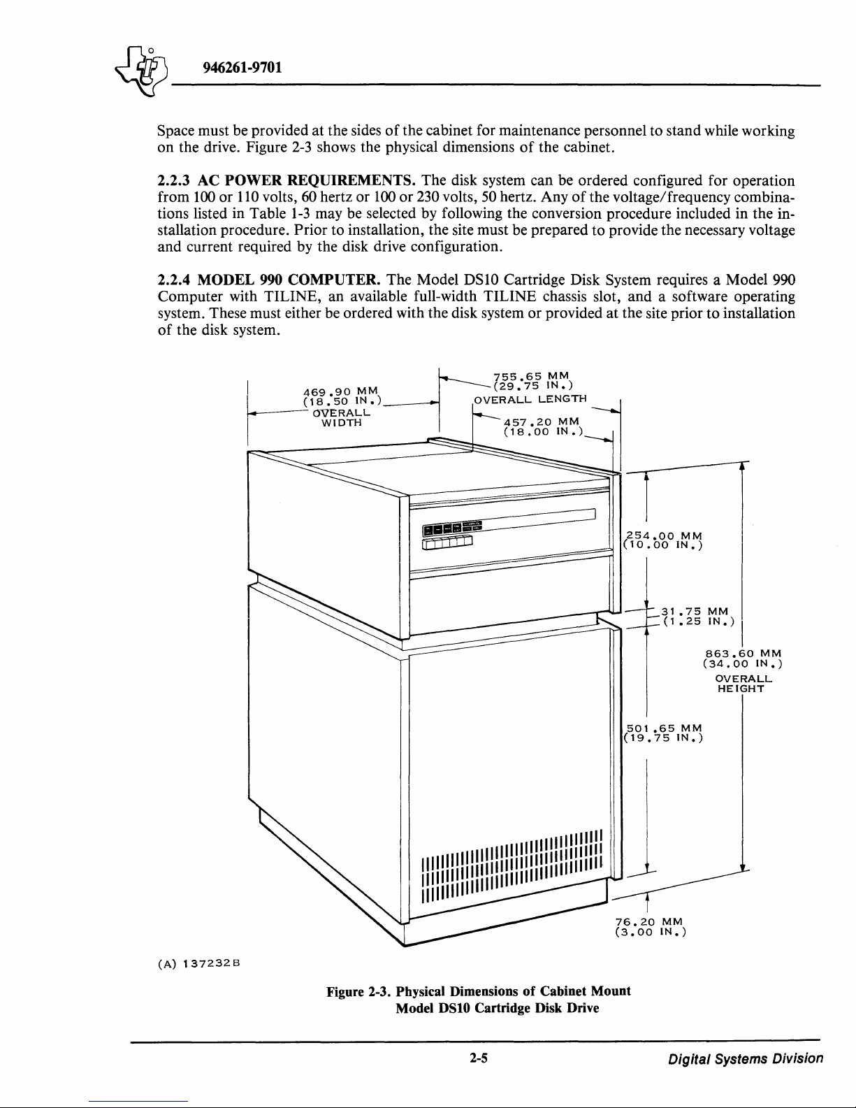
Space must be provided at the sides
of
the cabinet for maintenance personnel to stand while working
on the drive. Figure
2-3
shows the physical dimensions
of
the cabinet.
2.2.3 AC POWER REQUIREMENTS. The disk system can be ordered configured for operation
from
100
or
110
volts,
60
hertz or
100
or
230
volts,
50
hertz. Any
of
the voltage/frequency combina-
tions listed in Table
1-3
may be selected by following the conversion procedure included in the in-
stallation procedure.
Prior to installation, the site must be prepared to provide the necessary voltage
and current required by the disk drive configuration.
2.2.4 MODEL
990
COMPUTER. The Model DS10 Cartridge Disk System requires a Model 990
Computer with TILINE, an available full-width TILINE chassis slot, and a software operating
system. These must either be ordered with the disk system or provided at the site prior to installation
of
the disk system.
(A)
1372326
--17
755.65
MM
I
469
90
MM
(29.75
IN.)
r
18
:50
IN.)
OVERALL
LENGTH
j
OVERALL
WIDTH
457.20
MM
(18,00
IN.)
31.75MM
(1.25
IN.)
I
863.60
MM
(34.00
IN.)
OVERALL
HEIGHT
501.65MM
(19.75
IN.)
I I
11111111111111
I 1
11111
11111
11111
I!!
IIII!
11111111111111
1111111111111111
Figure 2-3. Physical Dimensions
of
Cabinet Mount
Model
DSIO
Cartridge Disk Drive
2-5
Digital Systems Division
Page 30

~
946261-9701
~-------
Table 2-2. Site Environmental Requirements for Model DSIO Cartridge
Item
Temperature
Humidity
Altitude
Pressure
16°
to
32°C
(60°
to 90°F) with a maximum gradient
per hour
10
to
90% relative with no condensation
-305 to
1060
maximum gradient
3048
m (-1000 to 10,000 ft.)
to
660 millibars = 793
of
5 mm
Requirement
to
513 mm
Hg
(3l.2
to
20.2 in.)
Disk
of
Hg
System
6.7°C
with
(12
oF)
2.2.5 SUPPORTIVE ENVIRONMENT. Table 2-2 lists the parameters for a supportive operating
environment for the disk system. Prior to installation, it must be ensured that the site meets the
requirements.
2.2.6 CABLING
RESTRICTIONS. Cable lengths affect the positioning
of
the equipment at the
site. The primary disk drive must be positioned so that the 6.10-meter (20-foot) interconnection
cables (cabinet mount) or 3.05-meter (lO-foot) interconnection (rack mount) may be connected to
both the disk drive and computer, and be routed along a convenient out-of-the-way path; they must
have sufficient slack at either end to provide access for maintenance and installation. In like manner, the secondary disk drive,
if
used, must be positioned
so
that the 1.83-meter (6.00-foot) cables
may be connected to both disk drives, and be routed along a convenient out-of-the-way path; they
also must have sufficient slack at either end to provide
~ccess
for maintenance and installation.
2.3
UNPACKING INSTRUCTIONS
The disk drives are shipped in containers as shown in Figures 2-4 and
2-5.
If
the disk drive
is
received
at the same time as the computer system, the disk controller, interconnection cables, and technical
manuals may be
bubble pack and ethafoam in the accessory package shown in Figure
'packed with the computer. Otherwise, these items are packaged in a polyethelene
2-4
(for rack mount) or in a
separate package for the configuration shown in Figure 2-5.
2.3.1
container
notify carrier immediately.
UNPACKING RACK MOUNT DISK DRIVE. Upon receipt
to
ensure
that
no physical damage occurred during shipment.
of
the container, inspect the
If
damage
is
apparent,
WARNING
The unpacked rack mount disk drive weighs approximately
kilograms
(148
quires assistance by another person
hydraulic lift, to avoid the possibility
Save
all shipping materials except where noted for use in reship-
ment
of
unit.
After ensuring
unpack the disk drive according
that
no damage has been done
pounds). When unpacked, handling
or
use
of
a portable hoist
of
back strain.
NOTE
to
the container
to
the following instructions:
or
of
the unit re-
its contents during shipping,
67
or
2-6
Digital
Systems Division
Page 31

~
946261-9701
~-------
(A)
137233
Figure 2-4. Rack Mount Disk Drive Shipping Configuration
2-7
Digital Systems Division
Page 32

4r
---------------------------------------------------------------------------------------------------------------------------------------
946261-9701
(A)
137234A
Figure 2-5. Cabinet Mount Disk Drive Shipping Configuration
2-8
Digital
Systems Division
Page 33

~
Jd7s\
______
946261-9701
(A)
_
137235
Figure 2-6. Placement
1.
Position container so
2. Cut and discard metal bands around shipping container.
3.
Open
assembly.
4. Remove manual from top
5.
Grasp accessory package
6.
Lift cardboard inner tube
top
flaps
that
of
shipping container and lift shipping container
by
of
Disk Drive for Shipping Bolt Removal
address label is upright.
of
accessory package and read unpacking instructions.
its sides, lift
off
disk drive and set aside.
WARNING
it
out
of
inner tube, and set it aside.
The following step requires at least two persons.
7. Grasp disk drive by placing fingers underneath sides
Rotate unit 90 degrees as shown in Figure 2-6
ing
bolt
heads underneath
wood
base.
and
of
set unit
unit
on
and
foam
by
flaps
lift clear
base
to
up
of
foam
expose
and
off
base.
mount-
9. Open plastic bag surrounding disk drive; press bag
now
be
lifted free
10. Remove three screws (Figure 2-7)
tronics cover.
11.
Remove carriage lock pin (Figure 2-8) by rotating
and
pulling straight up. Store pin
of
wood base
and
plastic protective bag.
that
hold electronics cover in place
head
on
side
of
magnet as shown in Figure 2-8.
2-9
down
of
around
pin 90 degrees counterclockwise
disk drive sides.
and
Digital Systems Division
Unit
remove elec-
can
Page 34

~
946261-9701
~~------------------
(A)
137236
12.
(990-1077-15-5)
Press in on outboard end
ward until free
side
of
card cage.
13. Lift card cage cover
The following steps are necessary only
installation.
14.
Remove control PWB and verify that SI settings are as shown in Figure 2-11.
15.
Replace control PWB.
Figure 2-7. Location
of
card cage cover clamp (Figure
of
screw. Lift up
off
and set aside.
on
free end
of
Electronics Cover Screws
NOTE
Refer to Figure 2-10 for steps
NOTE
2-9)
and move clamp end for-
of
clamp to release end hooked onto inboard
14
through 23.
if
a problem occurs during
16.
Remove sector PWB and verify that switch settings are as shown in Figure 2-12.
17.
Replace sector PWB.
18.
Remove servo PWB and verify that switch settings are
2-10
as
shown in Figure 2-13.
Digital
Systems Division
Page 35

~
946261-9701
~~------------------
TO
INSTALL:
INSERT
HOLE
COUNTERCLOCKWISE,
ALLOW
TO
TWIST
STRAIGHT
IN
AClUATOR
PIN
REMOVE:
90°
LEG
OF
PRES!:)
TO
PIN
NORMAL
FRAME;.
TO
RElURN
COUNTERCLOCKWISE
INTO
TWIST
DOWN
SMALL
900
AND
POSITION.
AND
PULL
UP.
CARRIAGE
BE
STORED
MAGNET
AS
LOCK
ON
SHOWN
PIN
SIDE
MAY
OF
(A)
137237
19.
20.
21.
22.
(990-977-35-11)
Replace servo PWB.
Remove data recovery PWB and verify that switch settings are
Replace data recovery PWB.
Remove r
/w
/ e PWB and verify that resistor modules are in orientation shown in Figure
2-15.
23.
Replace
r/w/e
PWB.
Figure 2-8. Carriage Lock Pin Location
2-11
as
shown in Figure 2-14.
Digital
Systems Division
Page 36

~'{j~o
_________________
_
~
946261-9701
(A)137238A
Figure 2-9. Card
Cage
Cover and Clamp Location
24. Replace card cage cover and clamp.
CLAMP
OUTBOARD
END
CARD
CAGE
COVER
25. Reinstall electronics cover. Disk drive
is
now ready for
attachment
of
slides.
2.3.2 UNPACKING DISK CONTROLLER. The disk controller
is
packaged in the special two-
piece ethafoam package shown in Figure 2-16. For the rack mount disk drive, the controller
is
shipped inside the accessory package shown in Figure 2-4. For the cabinet mount disk drive, the controller
is
shipped in a separately shipped accessory package similar to the one for the rack mount
disk drive. The unpacking procedures for the controller are the same for all configurations once the
accessory package has been separated from the rest
of
the shipping materials. The instructions are as
follows:
2-12
Digital
Systems Division
Page 37

~
946261-9701
~~------------------
DATA
RECOVERY
PWB
(A)
137239
1.
2.
(990-977-35-11)
Use
a utility knife
Remove disk controller package.
3. Remove tape holding two pieces
that
is
on top. Either the circuit board or the ethafoam spacer
4.
If
circuit board
package and turn it over.
Figure 2-10. Disk
to
slit tape holding down
is
exposed (it
is
Drive
PWB
Locations
top
flaps
of
accessory package.
of
ethafoam together and carefully lift
is
inside the ethafoam piece
2-13
you
off
the half
now exposed.
have lifted), reassemble
Digital
Systems Division
Page 38

~
j}r1.s\
946261-9701
______
_
~
INDICATES
SWITCH
POSITION
0000000
0000000
0000000
0000000
0000000
0000000
~
o 0 51 0 0 0
~r
INVALID
CYL. A DO.
DROP
READY
(DENSITY
NO
ACTIVE
ACTIVE
R. T .Z.S.
SPARE
(A)
137240
STATUS
FIXED D 15K
LOW
HIGH
RESETS
INTERRUPT
WIT H FAULT
)
100
ERRUPT
INT
TERRUPT
IN
FAULT
Figure 2-I
TPI
I.
Control
0
N
X
Y
X
0
5
1
8
'X
7
6
X
5
X
4
3
2
1
Xi
PWB
2-14
F
F
X.
READY
STAYS
FAULT
DISK
HIGH
LOW
INTER
DOESN'T
TRUE
INTE
DURING
200
TPI
FIXED
ACTIVE
ACTIVE
R.
T.Z.S.
SPARE
Switch Settings
NDITION
CO
RRUPT
RUPT
RESET
FAULT
Digital
Systems Division
Page 39

~
946261-9701
~
INDICATES
SWITCH
POSITION
..-
S4
rttB-B
0 0
0
.....
0
0
0
0
0
ONLY ONE
SWITCH
FROM
THIS
GROUP
CAN
BE
ON.
0
5
F
4
F
r
)(
1
2
'Y
)
3
4
1;(
5
'l
IX
6
7
I
I
-l
0
N
:)(
X
+ 1
+
+
+ S
74
+ 2
X 1
X2
32
16
FIX
FI
FI
FIX
FIX
FIX
FIX
FIX
ED
XED
XED
ED
ED
ED
ED
ED
DYNAMIC
FUTURE
2400
FIXED
FIXED
INDEX
2400
NO
DYNAN\IC
it.
INDEX
DELAYED
&
INDEX
SECTOR.e'
0 0
0 0
0 0
0
0 0
0
51
BRAKE
FIXED
INDEX
RPM
INDEX
TIMING &
INDEX
TIMING &
ANGLE
5O~'
RPM
BRAKE
TIMING
INDEX
TIMING
DIRECT
0 0
~
5 ..
.....
0 0
o 5
: 3
')
)
)(
-X
X
MULTI
SECTOR,
SINGLE
SECTOR
fiXED
INDEX
0
0
0
n n n
U U U
0 0 0
0 0
0
N
, 1
2
3
4
IX
5
X
6
7
8 IX
INDEX
OR
INDEX
NO
DYNAMIC
FUTURE
1500
RPM
FIXED
FIXED
INDEX
1500
RPM
DYNAN\IC
AT
SECTOR.t
PRIOR
INDEX
INDEX
ANGLE
FIXED
TIMING &
TIMING &
BRAKE
TO
ONLY ONE
SWITCH
THIS
GROUP
CAN
BE
BRAKE
INDEX
JOl0'
FROM
ON.
INDEX
INDEX
HARD
SOFT
-
TIMING
TIMING
SECTOR
SECTOR
I
~
F 2
X2
) 3
~
4
) 5
6
~
)(8
&.
.&
0
5
N
1
IX
7
IX
I~
F
Ix
+ 1
+
32
+
16
7
SCA
+
4C
+
2C
X 1 C
X 2 C
5 0
1 N
1
IX
2
IX
3
4
IX
CA
RT
ART
C
ART
C
RT
ART
ART
ART
ART
INDEX
INDEX
SOFT
HARD
TIMING &
TIMING &
SECTOR
SECTOR
(A)
137241
Figure 2-12. Sector
PWB
Switch Settings
2-15
Digital Systems Division
Page 40

~-------
"'iY
946261-9701
NORMAL
OPERATION
FEOT
ADJUST
~.
INDICATES
SWITCH
POSITION
ADDRESS
INTERlOCK
....
______________
....
CD
ON
CYLINDER
GOES
FALSE
X 3
ADDRESS
INTERLOCK
PULSE
DDDDDD~
0000000
0000000
0000000
0000000
0000000
I.'
52~:
II
I
51
I
-
II.
I I
III
I I I
III
II
II
I
l
200
TPI
I
I I
SPARE
ON
IXIXIX
X X X
.xXIX
5 1 1 2 3 4 5 6 7 8 9
1t*i
v -
OFF X
I'--
__
~---~JSPARE
I
100
TPI
TO
CURRENT
CYLINDER
BUT
V 2
NO
CHANGE
IN
ON
11\
NOT
FOR
ILLEGAL
AD
DR
ES:-.-S
"-+----t'o-I
CYLINDER
WITH
ILLEGAL
DURING
STROBE
FOR
SEEK
J-
\!I
ON
CYLINDER
GOES
FALSE
AD~ESS
OR
SEEK
TO
DURING
STROBE
FOR
1 X
CURRENT
C.
A.
ILLEGAL
ADDRESS
AND
SEEK
TO
CURRENT
ADDRESS
ILLEGAL
ADDRESS
DETECTION
ON~
CA ? 406
(200
TPI)
ILLEGAL
ADDRESS
CA
~
203
(100
TPt)
100
TPI
I 1 It
I
ON
IX
52
1 2 3 4 5 6 7 8 9
10
OFF
XIX
XIX[X[X
XlX:;
I I
200
~I
CA
~
0108
(200
TPI)
ILLEGAL
ADDRESS
OR
__
~
CA
~
204
(100
TPI)
FORWARD
END
OF
TRAVEL
ADJUST
CA ~ 415--..J
CD
SW3-1 & SW3-2
MUST
NOT
8E
ON
AT
THE
SAME
TIME.
HOWEVER,
THEY
CAN
BE
OFF
AT
THE
SAME
TIME.
(A)
137242A
Figure 2-13. Servo
PWB
Switch Settings
2-16
Digital
Systems Division
Page 41

946261-9701
~
INDICATES
~
0
0
000
0
0
0
0
nO
II
HARD
HARD
SOFT
1/2
1/4
112
1/4
SWITCH
POSITION
0
0
0
n
53
U
52
0
0
~
0
I
~
0
I
~
SECTOR
SECTOR
SECTOR
CELL
DATA
CELL
DATA
CELL
CLOCK
CELL
CLOCK
4
0
0
0
0
o
51
DO
0
0
I
0
:y
~
N
.
'I..
1
3
4
SiX
6
7
IX
X
SOFT
SOFT
HARD
1/4
1/2
1/4
1/2
CELL
CELL
CELL
CELL
)(2
.x
IX
--
SECTOR
SECTOR
SECTOR
DATA
DATA
CLOCK
CLOCK
HARD
2400
1500
1500
SPARE
SPARE
rEST
2400
TEST
SPARE
SPARE
SPARE
SPARE
SOFT
SECTOR
RPM
RPM
RPM
RPM
SECTOR
rX
X
XS
'J..
f<l
F
[Xl
){3
)(
)(
)
TEST
SPARE
HARD
SOFT
SOFT
HARD
SOFT
5
4
1
2
3X
4)(
6
;X
]
I
5 0
1 N
2 X
4
5
6
7X
SECTOR
SECTOR
SECTOR
SECTOR
SECTOR
0
N
SOFT
1500
2400
2400
SPARE
SPARE
Oi-J
1500
ON
SPARE
SPARE
SPARE
SPARE
HARD
Iy
X2
X3
'X6
SECTOR
RPM
RPM
RPM
FOR
ALL
COt..JF;GURATIOt"~S
RPM
FOR
ALL
CONFIGURATIONS
SECTOR
0
5
N
3
ON
FOR
1
IX
eX
4
5
X
7[X
ALL
CONFIGURATIONS
SPARE
SOFT
SECTOR
HARD
SECTOR
HARD
SECTOR
SOFT
SECTOR
HARD
SECTOR
(A)
1372688
5.
If
ethafoam
taped along its edges
6. Ensure jumpers (see Figure 2-17) are securely installed.
7.
Remove tape and lift circuit board
2.3.3
to ensure
carrier immediately.
UNPACKING CABINET MOUNT DISK DRIVE. Upon receipt
that
spacer is exposed, lift
no physical damage occurred during shipment.
Figure
2-14.
to
remaining
Data Recovery PWB Switch Settings
it
off
and
set
it
aside.
The
circuit
half
of
the package.
out
of
package.
If
damage
2-17
board
of
the container, inspect
is now exposed,
is
apparent, notify
Digital Systems Division
it
Page 42

"'iY
946261-9701
~-------
[!]
INDICATES
LOCATION
OF
PIN
1
RMl
ERASE
riB
IS
RM2
WRITE
00
00
-
-
(A)
137269A
DESCRI
ERASE
TPI
IE
PRE-ERASE
100
STRADDLE
100
ERASE
PRE-ERASE
200
200
STRADDLE
ERASE
X
*
RESISTOR
Figure 2-15. R/W/E
PTION
TYPE
MODULE
RM 1-(ERASE)
MOO.
75300100
NONE
75300100
75300200
USED
INDICATED
PWB
Resistor Module Orientation
TYPE
PIN
B
A
B
BY
2-18
1
MOD.
75300100
75300100
75300200
eX).
RM2-(WRI
TYPE
NONE
TE)
PIN
1
A
A
A
Digital Systems Division
Page 43

"'iY
946261-9701
~-------
ETHAFOAM
SPACER
DISC
CONTROLLER
(A)
137243
The unpacked cabinet mount disk drive weighs approximately 114
kilograms (252 pounds). When unpacked, bandling
quires
hoist
The unit can be rolled
Save
ment
at
least two persons,
or
hydraulic lift for transporting the drive over long distances.
all shipping materials except where noted for use in reship-
of
the unit.
Change 2
Figure 2-16. Disk Controller Shipping Configuration
WARNING
of
and
is
simplified by use
on
its casters over short distances.
of
NOTE
2-19
the unit re-
a portable
Digital Systems Division
I
Page 44

~
~,-------
946261-9701
o 0
J1
SPAREIN
1
SPAREIN2
DIAGNOSTIC
NOTE:
THE
LONG
INSTALLED
(J2)
AND
IT
MUST
OPERA
TI
D D
J2
TEST
o
J5
MAY
BE
NORMAL
VERSION
SELF-TEST
BETWEEN
GROUND
BE
REMOVED
ONS.
FOR
J4
JUMPER
THE
SPAREIN2
TEST
TO
RESUME
PURPOSES
PWB
LINE
ONLY.
D
J7
o
J3
o
J6
UGG047
UGC047
SPAREIN1
(A)143534A
UKC041
o
o
D 0
UKC038
SPAREIN2
Figure 2-17. Disk ControUer Standard Jumpers
EJD135
EJD133
o
EJD132
FINE
LINE
EHJ128
o
EHD127
EHD130
PWB
EJD130
D
EJG128
EJD127
VERSION
EHJ
135
EHJ132
o
EJB133
EHJ130
o
EJB128
EHJ127
2-20
Digital Systems Division
Page 45

'iY
946261-9701
~-------
After ensuring that no damage has been done
unpack the disk drive according to the following instructions:
1.
Position container so that address label
2.
Cut and discard metal bands around shipping container.
3.
Open top flaps
4.
Lift shipping container by flaps up and
5.
Use
a claw hammer or wrecking bar
Do not attempt to
6.
Using a hoist, portable lift, or another person, lift the disk drive up and
and set it on floor.
7. Lift the front
electronics cover.
8.
Remove three screws (Figure 2-7) that hold electronics cover in position and remove electronics cover.
of
shipping container and lift
lift disk drive alone
of
the rear cover
to
the container or its contents during shipping,
is
upright.
out
wood and ethafoam spacer.
off
assembly.
to
dismantle sides
WARNING
or
of
the disk drive and rotate
of
inner packing assembly.
by top assembly.
it
backward
off
the base
to
expose the
of
9. Remove carriage lock pin (Figure 2-8) by rotating head
and pulling straight
10. Reinstall electronics cover and reposition rear disk drive cover.
2.3.4 UNPACKING ACCESSORIES. The interconnection cables, whether for a primary
dary disk drive, slides (for rack mount only), and all manuals and paperwork shipped with the disk
drive are shipped wrapped in plastic bags in the accessory package.
accessories.
2.3.5 UNPACKING, HANDLING,
shipped in reusable corrugated shipping containers
entire container, including the disk cartridge, can be handled by one person. The shipping
container provides adequate storage protection for the disk cartridge with no degradation
performance when stored in specified environments
When storing disk cartridges in the shipping containers, do
stack the containers more than eight high.
up_
Store pin
AND
STORING DISK CARTRIDGES. The disk cartridges are
on
side
of
as
CAUTION
magnet as shown in Figure 2-8.
that
are lined with polyurethane foam. The
described in following paragraphs.
pin 90 degrees counterclockwise
or
secon-
Open the bags and remove the
of
not
2-21
Digital
Systems
Division
Page 46

~
2.3.5.1 Unpacking Disk Cartridges.
___
~
__ U __
l_-~_O_l
________________________________________________
__
CAUTION
Disk cartridges are precision instruments. Tolerances
of
few millionths
handling and storing
time and protect valuable data recorded on the disks.
Open the shipping carton and unpack the disk cartridge
1.
Inspect shipping container for any evidence
2.
Remove disk cartridge from shipping container and protective bag.
3. Remove cartridge from
visual inspection
4. Carefully clean inside
cloth moistened with water
material from entering the disk area.
5. Always keep
Dust and
lint
Do not, under any circumstances, attempt to use a disk cartridge that
you suspect
disk drive.
of
top
and
can accumulate
is
an inch are common. A little precaution in the
of
disk cartridges can prevent costly rerun
of
bottom
bottom
of
disk cartridge
bottom
damaged because such usage can cause damage
cover and
protective disk. Look for dents
top
or
isopropyl alcohol.
covers
in
of
canister together when the cartridge is
an open canister and may later contaminate the cartridge.
CAUTION
as
follows:
damage.
tum
upside down on
and
bottom
Be
as
smal1
as
a
top
cover. Perform
or
scratches.
covers with a clean, lint-free
careful
to
prevent any foreign
not
to
the
in use.
CAUTION
The disk cartridge used with the Model
must be in accordance with Texas Instruments Specification
937507. The recording surfaces in the disk cartridge must be
error-free.
The case,
cover (see Figure 2-18). The handle locks with the cartridge spindle, and the disk cartridge should be
carried from place
vironment as the disk drive
hour prior
2.3.5.2 Handling Disk Cartridges. The following precautions should be observed when handling
disk cartridges.
or
canister,
to
use.
To prevent dust, dirt, and foreign material from entering a disk
cartridge and contaminating the disk, the disk cartridge should
always be in its cover when not in use.
of
a disk cartridge consists
to
place by the handle. The disk cartridges should be stored in the same room en-
or
brought into the room for temperature conditioning no less than one
of
CAUTION
2-22
DS
1 0 Cartridge Disk Drive
a plastic top cover with a handle and a bottom
Digital Systems Division
Page 47

)1;,
______
_
~
946261-9701
HANDLE
(A)
137245
COVER
RELEASE
BUnON
Figure 2-18. Disk Cartridge
1.
Carry disk packs from place to place using the handle.
OISK
CARTRIOGE
2.
Always reassemble the disk cartridge by setting the dust cover down on a solid surface,
then placing the cartridge into the dust cover.
3. Never set the disk cartridge on any surface without the dust cover in place.
4.
Never stack disk cartridges or set anything on top
of
a disk cartridge.
2.3.5.3
Storing Disk Cartridges. The following precautions should be observed when storing disk
cartridges.
1.
Always store the disk cartridges in the operating environment listed in Table 2-2.
2. Disk cartridges that have been stored in,
or
subjected to, environments outside the range
listed in Table
2-2
should be conditioned to the environment listed in Table 2-2 for at least
24
hours prior to use. During this period
of
conditioning, the cartridges should be re-
moved from their containers.
3.
For long term storage, store the disk cartridges in their original shipping containers no
more than eight
high. The containers provide protection against dust and debris, large
environmental changes, contamination
by
chemicals, and physical damage.
2-23
Digital
Systems
Division
Page 48

J17)\
______
_
"'i:Y'
946261-9701
2.3.6 VOLT AGE CONVERSION PROCEDURES.
If
the disk drive
is
to
be operated from any
of
the voltages listed in Table
1-3
other
than
100
volts, 50 hertz,
110
volts,
60
hertz,
or
230 volts, 50
hertz, the following procedure should be performed
at
this time to prepare the disk drive.
1.
Remove voltage adapter assembly (Figure 2-19) at lower left
of
rear
of
the drive next to
power cord.
NOTE
For
each voltage option, there are two jumpers. One end
of
each
jumper
is
fixed (pins 14 and 15) and should
not
be removed.
2. Refer
to
Table
2-3
for proper jumper connections for desired voltage.
3. Pull moveable end
of
jumper(s)
out
of
plug and reinsert into location indicated by Table
2-3.
4. Install jumper plug into connector.
5.
If
necessary, remove existing line cord plug and replace with a new one (customer-
supplied)
to
provide proper mating
of
line cord with power outlet.
6.
Alter voltage designation on
ID
plate at rear
of
disk .drive to reflect new operating
voltage.
2.4
INSTALLATION
Installation
of
the disk system consists
of
attaching slides to the rack mount disk drive
and
installing
the drive into a rack,
or
positioning a cabinet mount disk drive; attaching cables to the disk drive(s)
and routing the cables to the computer chassis; preparing the computer chassis
to
receive the disk
controller; preparing the disk controller slave address; and installing and cabling the disk controller.
2.4.1
INSTALLATION OF RACK MOUNT DISK DRIVE. Installation
of
the rack mount disk
drive consists
of
attaching the rack slides to the disk drive and then installing the assembly into a
properly positioned rack. The following procedure should be observed.
NOTE
Refer
to
Figure 2-20 during the following steps.
1.
Attach a plastic slide mount
and
a plastic keyed slide mount to each side
of
the disk drive
with 8-32 x 5/8-inch panhead machine screws and
No.8
internal-tooth lock washers.
NOTE
Orient
V-groove channel in unkeyed plastic mount downward.
Orient flat sides
of
keyed mounts inward and downward.
2.
Attach a plastic stabilizer to each side
of
disk drive with 8-32 X 1/2-inch panhead
machine screws,
No.8
internal-tooth lock washers, and
No.8
flat washers.
2-24
Digital
Systems Division
Page 49

~-------
~
946261-9701
9
PIN
12
(FIXEDj
3
6
000
0000
00000
4 7
10
13
BACK
VIEW
(WIRE
SIDE)
4
7
10
13
00000
000
000
3 6
PIN
15
(FIXED)
PI
N
14
(FIXED)
JUMPER
NO.
1
P'N
14
(FIXED)
JUMPER
NO.
2
PIN
15
(FIXED)
9
JUMPER
NO.
3
PINS
t 1 AND
12
(FIXED)
(A)
137246
FRONT
VIEW
(PIN
SIDE)
Figure 2-19. Voltage Jumper Plug and Connector
NOTE
The stabilizers should be mounted with their keys extending
downward. Leave stabilizers slightly loose at this time.
3.
Adjust the slides
so
that the dimensions
of
the assembly correspond to those shown in
Figure 2-2.
4. Adjust and secure the front mounting brackets
so
that the flange fronts are flush with
fronts
of
slides
(See
Figures
2-20
and 2-21).
Digital Systems Division
Page 50

946261-9701
~
Table 2-3.
Disk
Drive
Input
Voltage Jumper Connections
Voltage
100
110
120
130
140
150
160
170
180
190
200
210
220
230
240
250
Jumper
Fixed Pin
14
14
14
14
14
14
14
14
14
14
14
.
14
14
14
14
14
No.1
Moveable Pin
4
3
2
1
6
5
4
3
2
1
6
5
4
3
2
Jumper
Fixed Pin
15
15
15
15
15
15
15
15
15
15
15
15
15
15
15
15
No.2
Moveable Pin
7
7
7
7
8
8
8
8
8
8
9
9
9
9
9
9
NOTE
The flanges can be located as much as
front
of
the slide ends
Maximum extension
to
of
the unit
accommodate certain rack dimensions.
out
action.
5. Adjust and secure rear mounting brackets and cable retractor (left side only) as shown in
Figures 2-20 and 2-21.
6. Ensure that the white plastic button in each front slide mounting bracket
two holes provided so that the button
ing and nonmoving parts
of
the slides.
is
7. Extend slides to full extension. The intermediate catches
must be released
8. With the aid
all four plastic slide mounts rest
of
on
both sides. Slides lock
an
assistant
or
a lift, set the disk drive
on
the top edges
. mounts engage notches in slides.
CAUTION
Use
only 8-32 x 5/16 screws for mounting slide
mount.
If
longer screws are used, the ribbon cable on the left side will
be damaged.
25
millimeters (one inch) in
of
the rack
on
top and can act as a bearing between the mov-
at
full extension.
is
reduced by this
at
457 millimeters
on
top
of
the slides, ensuring that
of
the slides and that keys
to
plastic-keyed slide
is
in one
(18
of
inches)
of
front
the
2-26
Digital Systems Division
Page 51

'iT-'
946261-9701
~.-------
_
MOUNT
RAJ
L ON
MOUNT
PLASTIC
MOUNT
PLASTIC
STABILIZER
BEHIND
BOTH
BEHIND
SLIDE
REAR
SIDES
SLIDE
(A)
13724
SA
LATCH
MM
ASSEMBLY
(30
IN.
IS
PURCHASED
(973712-0006
RACK)
LATCH
NOTE:
KNOB
THE
946738-0010
ARE
TAPPED
SUPPUED
ANGLE
FOR
WHEN
ASSEMBLIES
762
DISK
Figure 2-20. Rack Slide Assembly Mounting
AS
AND
PART
FRONT
MOUNTING
FOR
1778
THE
CABLE
OF A DS990
NOTE:
SLIDE
BRACKET
MM
(70
CARRIER
KIT.
IN.)
RACK
996745-0001
1-2'7
Digital
Systems
Divis/on
Page 52

~
j}5\
946261-9701
__
-----
u
(A)
137698A
9. Coat threads
and install through each slide into keyed slide mounts.
622.30
(24.50
o
EACH
SCREW
REARWARD
Figure 2-21. Rack Mount Slide ConfIgUration (Right Side Only)
of
HOLE
two
IN
MOST
8-32
x 5/16-inch panhead screws with Grade C Loctite (or equivalent)
MM
IN.)
,.....
EACH
SCREW
FORWARD
o
HOLE
u
IN
10. Adjust stabilizers installed in step 2 to prevent wobbling and
to
provide smooth slide
operation. Tighten stabilizers.
11.
Attach latch assembly to disk drive with
lock washers and No. 8 flat washers. Leave screws slightly loose
12.
Insert knob through front panel and attach to latch assembly with an
panhead machine
8-32
and an
13.
Adjust latch so it catches front vertical rack rail, securely holds disk drive in retracted
hex machine nut.
position, and releases easily when knob
2.4.2 INSTALLATION
of
disk drive consists
placing the unit in the space provided for it and leveling the unit. Leveling
screw, a
No.8
OF CABINET
internal-tooth lock washer, an
MOUNT
8-32
x 5/8-inch panhead machine screws.
at
this time.
8-32
is
pushed to left.
DISK DRIVE. Installation
of
should be performed after the interconnection cables have been connected
Level
the cabinet
1.
Remove jack screws from plastic container.
2.
Lift one side
3.
Start jack screws into threaded holes beside casters. Thread screws into holes far
enough
as
follows:
of
cabinet and support it high enough to insert jack screws.
to
allow casters to touch floor when unit
is
lowered.
No.8
8-32
x 5/8-inch
x 1/4-inch spacer,
the cabinet mount
to
the disk drive.
4.
Lower cabinet and repeat steps 2 and 3 for opposite side.
5.
Unscrew jack screws until casters are raised
2-28
off
floor.
Digital Systems Division
Page 53

4P
946261-9701
----------------------------------------------------------------------------
6.
Using
a level
as
reference, adjust jack screws until cabinet
is
level along
all
four sides
of
cabinet. top.
2.4.3
COMPUTER CHASSIS PREPARATION FOR DISK CONTROLLER.
If
the disk drive
system
is
shipped
as
part
of
the Model 990 Computer system, the computer chassis
is
shipped with
chassis slots assigned, interrupt connections properly made, etc. Normally, the disk controller
is
in-
stalled in computer chassis slot 7 (in a
13-s10t
chassis), its TILINE address
is
set to
>FFCOO
(the sym-
bol >indicates hexadecimal), its interrupt level
is
set at
13,
and the access granted connections are
permanently made. No further preparation
is
necessary for a computer chassis shipped with a disk
controller installed.
If
the disk system
is
shipped separately from the initial computer system, or if
the configuration
is
to be changed, the computer chassis must be adapted for the new configuration.
If
a nonstandard configuration
is
used, refer to the computer hardware reference manual for the
proper model (990/5,
990/10, or 990/12). (See the preface for the formal titles and part numbers
of
these manuals.) In addition, the power capacity
of
the computer chassis must meet the requirements
of
the disk controller and all other boards installed in the chassis. The disk controller requires + 5
Vdc at 5.5 amperes and -12 Vdc
at
0.03 ampere.
If
a computer chassis slot other than slot 7
is
selected, the TILINE access granted signal chain must
be modified. This
is
accomplished by removing the jumper in the access granted circuit, as described
in paragraphs 2.4.3.1 and 2.4.3.2.
If
the controller
is
not purchased as part
of
the system, the user may have to make the interrupt con-
nections as part
of
the board installation. Paragraphs 2.4.3.3 and 2.4.3.4 describe the interrupt
connections.
TILINE address settings and Interrupt assignments must be coordinated with the operating system
software.
If
you are adding on
to
a previously-purchased system, refer to the system generation in-
structions in the operating system documentation upon completion
of
the hardware installation.
2.4.3.1 Reconfiguring Access Granted Circuit for
New
Chassis Slot (6- and 13·Slot Cbassis). The
TILINE
is
a common data path that
is
connected to all slot positions in the 990 chassis. Users
of
this
bus fall into two major types: masters and slaves.
Shive devices are addressed by master devices and
commanded to accept or transmit data.
Some TILINE peripherals, including the disk drive con-
troller, have both master logic and slave logic.
In order to resolve conflicts between mUltiple masters contending for TILINE control, a positional
priority scheme
is
used. The TILINE access-granted signal, which established positional priority
among masters,
is
wired along the P2 side
of
the chassis. The TILINE master installed in the highest
numbered slot has the highest priority, with priority decreasing with each slot toward the central
processor location (or slot
1).
The TILINE access granted signal enters each master on backplane connector P2, pin 6. The signal
leaves the master on pin 5
of
P2. Logic circuitry
on
the master controller allows the access granted
output
to
be inhibited to lower priority masters.
For chassis slots not occupied by TILINE masters, jumpers
or
etch on the backplane connector pins
are installed to ensure continuity.
By
convention, the jumpers are installed
at
all available slot loca-
tions except slot
7.
Slot 7
is
reserved for the fIrst TILINE master device (positional priority); in this
case, the disk controller. Additional TILINE masters may be inserted at slot positions
of
higher
or
lower priority if the jumper connected between P2-5 and P2-6
is
removed at the selected slot
locations.
Digital
Systems
Division
Page 54

~
946261-9701
~-------
Installing a disk controller in a location other
jumper
cess granted lines between the highest priority master
preserved.
be installed to preserve continuity
Current
tor
in Figures
for
previously, the continuity
central processor must be preserved. Therefore:
If
or
cess granted jumpers.
(P2-5
to
P2-6) be removed from the chosen slot,
This means
production assemblies have the
side
of
the
motherboard
2-22
and
the
selected chassis slot,
1.
All
slots
access
2. All master controllers
the
chassis is
jumper
an
2-23), it is necessary
1.
Tum
off
that
2-23.
Simply remove the
of
other
than
installed.
early production version (Le. t
to
remove
For
an
power and unplug
if
an
intermediate slot is assigned
and
to
TILINE
when all boards are removed from the chassis. These jumpers are shown
and
reinstall all circuit boards in their proper location. As noted
the
TILINE
those containing
must
be installed in their proper location.
the
back cover
these chassis, the following steps should be followed:
the
than
slot 7 requires that the
allow the priority system
access granted jumpers accessible from the connec-
jumper
access granted line from
plug (or cut the
TIliNE
if
it
does
and
power supply
computer
ac line cord.
TILINE
and
that
the continuity
and
the central processor·
to a TILINE
the
master controllers
not
have jumpers as shown in Figures
to
master,
to
function.
jumper,
highest
gain access
of
that
if
the
jumper
TILINE
must
have
to
the
access granted
TILINE
board
master must
master
the
ac-
must be
is
a wire)
to
TILINE
2-22
the
TILINE
the
ac-
WARNING
Lethal voltages are exposed when
supply capacitors may retain charges long
2. Remove
fastened
If
3.
the chassis is
visible
any
a. Disconnect the color-coded connectors from
b.
c. Carefully pull
the
left access cover (as viewed from
by
four
or
six hex head machine screws.
a·
13-slot chassis with a 20-ampere power supply, slots 1 through 6 are
above'
other
supply board.
Unscrew
frame and
bottom
from the motherboard.
the
power supply.
slots, remove the power supply
the
machine screws and standoffs
to
the
motherboard.
the
power supply board straight forward until the connector
center
of
the
power supply board is disengaged from the pins protruding
Lift
the
To
work
the
power supply board
access cover is removed. Power
after
ac
power
the
front
on
these slots, proceed
as
follows:
the
that
is removed.
of
the chassis). The cover
component
secure
out
the
of
to
step 4.
side
power supply
the
chassis.
To
work
of
the power
to
at
is
on"
the
the
2·30
Digital
Systems Division
Page 55

~-------
~
946261-9701
ASSY.
94501
()-OOOl
REV
( )
P4ID
R2
SLDT 1 HAS
NOJUMPER
P2
At
SLDT 2 .AJMPER
A2
A3
SLDT 3 .AJMPER
I I
A4
SLDT 4 .AJMPER
I I
SLDT S .AJMPER
AS
SLDT 6 HAS
NO
.AJMPER
A6
R3m
R1
NOTE:
JUMPERS
ARE
REMOVABLE
JUMPER
PUIGS.
(A)
138671
Figure 2-22. TILINE Access Granted Jumper Locations for
6-Slot Chassis (Current Production)
4.
The rear
of
the motherboard
is
now exposed. The P2 connectors are at the left side,
nearest the fan. Refer to Figure
2-24
for
views
of
the left end
of
the P2 connector in a
13-s10t
and
6-s10t
chassis.
5.
In a
13-s10t
chassis, the TILINE access granted jumpers (P2-5 to P2-6) are wire jumpers
soldered to the connector pins as shown in
view A of
Figure 2-24. To remove a jumper,
clip the jumper at each end as close
as
possible to the pins and remove the wire.
6.
In a
6-s10t
chassis, the jumpers are part
of
the printed wiring board etch as shown in
view
B
of
Figure 2-24. Note that pins 1 and 2 are concealed by the ground plane. To remove a
jumper, cut the jumper etch at two points with an X-acto· knife and lift
off
or scrape
away the
excess
conductor.
2-31
Digital Systems Division
Page 56

~
946261-9701
~-------
0
0
0
0
0
0
0
I
0
1
I
10
I
10
I
10
I
I
I
I
0
1
I
10
I
10
I
I
0
1
I
10
I
10
I
I
0
1
I
I
10
I
I
I
I
tAt
I
J2
iA
iB
P2
At
A2
A3
A4
AS
A6
A7
A8
A9
A10
Al
A12
A13
ASSY.
P3
rn
1
P4[ll
945015-0001
Pt
P2
REV
0--0
I
I
I
I
I I
I
I
I
I
I
I
(R)
SLOT 1 HAS
SLOT 2 JUMPER
SLOT 3 JUMPER
SLOT 4 JUMPER
SLOT 5 JUMPER
SLOT 6 JUMPER
SLOT 7 JUM
SLOT 8 JUMPER
SLOT 9 JUMPER
SLOT
to
SLOT
t t
SLOT
t 2
SLOT
13
NO
PER
JUMPER
JUMPER
JUMPER
HAS
JUMPER
NO
JUMPER
NOTE:
(A)
138672
JUMPER
WIRE
WHICH
Figure 2-23. TILINE Access Granted Jumper Locations for
MAY
BE
EITHER A REMOVABLE
MUST
BE
CUT.
13-Slot Chassis (Current Production)
2-32
JUMPER
PUJG
OR
A
Digital
Systems Division
Page 57

.
4P
----------------------------------------------------------------------------
7.
8.
946261-9701
To
install a jumper, solder a short length
To reinstall the power supply, proceed
CAUTION
of
as
follows:
#26
AWG
wire between
P2-5
and P2-6.
a.
b.
c.
d.
*X-acto
The
motherboard are subject to bending
power supply
Slip
male
pins protruding from the lower center
if
the mating connector on the
is
not properly aligned with these pins.
of
the power supply over the cable harness and into the side
the
of
the chassis. The
metal-shell jumper connector (for the standby power supply) should appear at the
bottom center
Align
the power supply circuit boards on the two alignment pins and carefully
of
the power supply board.
slide the board straight back so that the pins protruding from the motherboard
slip into the connector on the
is
blocked by the power supply board.
power supply circuit board. The
view
of
these pins
Reinstall the machine screws and standoffs that hold the power supply in place.
Do
not omit the lockwashers,
made
by
the machine screws and standoffs.
Reconnect the power supply to the wiring harness
as
both mechanical and electrical connections are
by
installing the color-coded
plastic connectors.
is
a registered trademark
A.
13-SLOT
CHASSIS.
of
X-acto Corporation
AND
~~~~6''p~N
PINS
2 .
B.
6-SLOT
r----.v-.-P;;.;.I
1
~''''.
~
....
__
CHASSIS.
TILINE
GRANTED
.AJMPER
N .... S ....
••
........
__
ACCESS
(TLAG)
ETCHED
TO
PI
N 6
GND
PLANE
STRAPS
(A)
·NOTE
133946A
THESE
THE
ARE
POWER
Figure 2-24. TILINE Access Granted Jumpers (Pl-5 to Pl-6)
REAR
VIEWS
OF
THE
SUPPLY
SIDE.
990
on tbe Model 990 Backpanel
2-33
MOTHERBOARD.
I. E ••
VIEWS
FROM
Digital Systems Division
Page 58

~
946261-9701
~-------
9. Reinstall the cover removed in step
10.
Record the new slot assignment on the configuration chart affixed to the chassis.
2.4.3.2 Reconfigurlng Access Granted Circuit for
the TLAG jumpers in the
with eight individual switch sections. These switches are accessible from the rear
chassis, as shown in Figure 2-25.
performed.
1.
Turn
off
power and unplug the chassis ac line cord. Allow about
supply bleeders
Opening the chassis rear cover (power panel) exposes high voltages
the ac line cord is installed in a live socket.
filter capacitors on the power module.
The wire hinges
pivot beyond 90 degrees. Attempts
beyond 90 degrees may damage the hinge mountings.
17-s10t
to
chassis
To
set
discharge the power supply capacitors.
on
the chassis rear cover
2.
New
Chassis Slot (17-Slot Chassis). Continuity
is
controlled by two socket-mounted
or
check these switches, the following steps should be
WARNING
Do
not
contact the large
CAUTION
do
not
allow the cover
to
open the chassis rear cover
DIP
30
seconds for the power
to
switches, each
of
the
17-s10t
if
of
2. Using a coin or flat-bladed screwdriver, release each
chassis rear cover.
wire hinges, and then open the cover
as viewed from the rear
to
3. Refer
slots. Set the appropriate switch segment
master device, such as the disk controller. All other switch segments should be
4. Refer
5. Rotate the door
Grasp the rear access cover
mounting position against the chassis.
6.
Using a coin or screwdriver, lock the
in position.
Figure 2-26, which shows the correspondence between switch sections and chassis
to
paragraph 2.4.3.4
is
There
and modules mounted inside the rear access cover as the door is
closed. Do not force the
Pull the cover straight back
of
the chassis.
if
interrupt assignments are
CAUTION
a possibility
to
a position parallel
of
interference between heat sinks in the chassis
door
at
the left and right sides and push it straight back
to
the 9O-degree position. The hinges are on the right
OFF for any slot which
closed
if
resistance is felt.
to
the rear
11
quarter-turn latches which hold the access cover
of
the
11
quarter-turn latches on the
38
millimeters (1.5 inches)
is
assigned to a TILINE
to
be changed.
of
the chassis, with hinges fully extended.
to
extend the
ON.
to
its
7.
Record the new slot assignment on the configuration chart affixed to the chassis.
2-34
Digital Systems Division
Page 59

"i:V
946261-9701
~-------
INTERRUPT
PLUG
S2
S1
(A)141779
Figure 2-25. Interrupt Plug and TLAG Jumper Switches in the 17-Slot Chassis
2-35
Digital Systems Division
Page 60

o
~:
-
Ib
-
ON =
TLAG
JUMPERED
ACROSS
SLOT
(P2-6
TO
P2-5)
OFF = TLAG
NOT
JUMPERED -CONTINUITY
REQUIRES
TILINE
CONTROLLER
CHASSIS
SLOT:
(A)141767A
2
3
S2
4
5
6 7 8
9
CHASSIS
SLOT:
10
1 1
12
S1
13
14
15
16
8
r--
,.,
I I
L."
NIC
NOTES:
1.
SWrTCHES
ARE
SHOWN
SET
FOR:
2.
3.
SYSTEM
DISK
CONTROLLER
979A
TILINE
MAGNETIC
TAPE
CONTROLLER
FD1000
TILINE
FLEXIBLE
DISK
CONTROLLER
-
SLOT
11
-
SLOT
12
-
SLOT
15
EACH
SWITCH
SECTION
MUST
BE
ON
UNLESS A TILINE
MASTER
CONTROLLER
IS
INSTALLED
IN
THE
CORRESPONDING
CHASSIS
SLOT.
TILINE
PRIORITY
SYSTEM
WILL
NOT
WORK
IF
SWITCHES
ARE
SET
INCORRECTLY.
SLOT
17
DOES
NOT
REQUIRE A SWITCH.
Figure 2-26. 17-Slot Chassis TLAG Jumper Switch Settings
Page 61

Jd75\
~
______
2.4.3.3 Interrupt Connections (for 6-and 13-Slot Chassis). Interrupt connections required to interface peripheral equipment to the
customer. These interrupt assignments are coordinated with the software supplied with the system.
However, if the controller
terrupt connections as part
to find the controller interrupt assigned to interrupt level 9, which
dard chassis configuration.
have to be changed, or a different interrupt level assigned to the software.
The 990 processor has
to the processor, has the highest priority. Interrupt levels 3, 4, and 6 through
which are available for assignment to peripheral controllers installed in the chassis. Interrupt level
assignments must be coordinated with the software, so that the processor may correctly respond
(and clear) the interrupts.
Chassis backplane wiring brings the interrupt output lines from slots 2 through 3 and the processor
interrupt lines to wire-wrap pin headers adjacent to slot
the circuit board interrupt outputs to the processor interrupt inputs. These jumpers may run directly
from pin to pin, or may be mounted on jumper plugs which slip over the pins. Figure
jumper plugs installed in the chassis. The jumper wires are omitted for clarity.
946261-9701
990
processor are usually made before the system
is
not purchased as part
of
the board installation. Standard Texas Instruments software expects
If
the controller
16
interrupt levels, numbered ° through
of
the system, the user may have to make the in-
is
installed in slot 9 or
is
delivered to the
is
connected to slot 8 in the stan-
11,
the interrupt jumpers
15.
Interrupt level 0, which
15
are external inputs
1.
Jumper wires between the pins connect
2-27
is
internal
shows the
_
will
to
(A)
FRONT
133096
OF
II
II
A
CHASS
IS
PI
Al
A2
A3
A4
A5
REMOVE
LOCATIONS
AND
Figure 2-27. Location
CIRCUIT
WIRE-WRAP
FOR
ACCESS
PIN
INTERRUPT
(MATED
TO
'(Uflr
L
I
I
I I
BOARDS
IN
FIRST
TO
JUMPER
HEADERS
of
Interrupt Jumpers
JUM
PER
W/W
FIVE
PLUGS
PLUGS
PIN
HEADERS)
~1J2
RII
II
II
II
(6-
and 13-Slot Chassis)
P2
Al
A2
A3
A4
.A5
II
=
>
w
0::
II;
0
II b
2-37
Digital Systems Division
Page 62

~
946261-9701
~-------
There are two rows
board
the
48 pins in a
possible circuit board interrupt outputs. This allows multiple interrupts to be connected to one
interrupt level.
Interrupt pin assignments are shown in Figures 2-28 and 2-29, which are views
as seen from the jumper wire side. The X marks identify jumper plug positions which have no corresponding pins
responding pins
The configuration chart
Any modifications should be recorded
The detailed procedure for assigning and changing interrupt levels
reference manual for the 990 computer (see preface). The information presented here
mary
to
13-s10t
of
that
the
chassis for special configurations, such
13-s10t
procedure.
of
pins in the header. The top row has
15
interrupt levels
chassis
on
the header. The 0 marks identify jumper plug positions which have no cor-
on
the earlier production header.
on
of
or
20 pins in a
top
of
the chassis details the interrupt level and chassis slot assignments.
the processor. Additional pins on the top row are provided
as
6-s10t
chassis. Two
on
the chart.
15
pins connected through the mother-
CRU expansion. The bottom row contains
of
these pins are wired
of
is
presented in the hardware
to
the jumper plugs
is
each
of
the
a brief sum-
CAUTION
Do not remove
while power
or
is
applied
install any circuit
to
the 990 processor.
board
or
modify any jumper
in
To gain access
interrupt jumpers
output
the controller, the interrupt
jumper should be run from 8P2 pin to the selected interrupt level input to the processor. Level 9
is
9
After completing any interrupt jumper modifications, carefully reinstall the removed circuit boards
(component side up) according to the configuration chart fastened to the top
Update the configuration chart
of
standard for Texas Instruments tape control software. A jumper
as
part
to
the interrupt jumpers, remove the circuit boards installed in slots 1 through
will
be visible
a full-sized board is
of
the standard 990 chassis configuration.
on
the motherboard just above the slot 1 connectors. The interrupt
on
P2
of
the assigned slot location. Therefore,
output
to
will
be found at 8P2
correspond
of
the
wire-:-wrap
is
installed between 8P2 and
to
the interrupt jumper modifications.
5.
The
if
slot 8
is
chosen for
pin header. A single
level
of
the computer.
NOTE
System software
the computer. Any deviations from standard interrupt configurations must be brought
before
or
during software installation.
is
highly dependent on the interrupt structure
to
the attention
of
the system programmer
of
2-38
Digital Systems Division
Page 63

946261-9701
~
LOCATION
CHASSIS
JUMPER
2Pl
2P1
3Pl
3Pl
4Pl
4Pl
5P1
5Pl
6Pl
6Pl
6-SLOT
INTERRUPT
PLUG
[R]
0
[!]
0
[E]
0
0
0
0
0
U
U
0
0
0
0
0 0
DOD
NOTE:
r:1
I!J
1A1J3
l..EVEL
PINS
BACKPLANE
1
2
3
4
5
NOT
LOCATION 2 P2
INSTALLED
PI N 'HEADER
6P2
6P2
5P2
5P2
4P2
4P2
3P2
3P2
2P2
IN
JUMPER
EDGE
0
0
0 0
0
0
0 0
0 0
0 0
0
0
WIRE
VIEW
0
0
0
0
0
0
1
AI
J2
LEVEL
6
7
8
9
10
11
12
13
14
15
(A)
138673
Figure 2-28. 6-Slot Chassis InterrUpt Jumper Plugs
2.4.3.4 Interrupt Connections
a 70-pin connector accessible from the rear
tor
to
make the interrupt level
of
the chassis backplane as shown in Figure 2-25.
The jumper assembly
level assignments.
is
If
it should become necessary
chase a special variable jumper assembly
shows the pin assignments
To
gain access
to
the interrupt
paragraph 2.4.3.2, steps 1, 2, 5,
Remove the interrupt jumper assembly by gently rocking it
and
then pulling straight back.
for
17-Slot Chassis. Interrupt lines in the
of
the chassis. A jumper assembly plugs into the connec-
to
chassis slot connections. This assembly appears
a PWB because it should not be necessary
to
change interrupt levels, the customer may pur-
or
modify the etch
on
the interrupt connector.
jumper
assembly, open the chassis rear access cover as described in
and
6. Observe all cautions
on
the fixed jumper card. Figure 2-30
and
warnings.
up
and
17-s10t
to
alter the standard interrupt
down
chassis are wired
at
the lower right
to
loosen the connector
to
When reinstalling the assembly, make sure the pins are properly aligned before applying mating
force.
It
is
possible
Note
that
to
pin 1
install
is
at
CAUTION
the
interrupt jumper assembly upside down.
the
bottom
of
the interrupt connector.
2-39
Digital Systems Division
Page 64

~---~--
'i1"
946261-9701
13-SLOT
CHASSIS
INTERRUPT
JUMPER
PLUG
lAI
J3
LOCATION
2PI
(PIN
66)
2PI
(PIN
66)
0
0
0
(8]
ALTERNATE I 3-SLOT
CHASSIS
INTERRUPT
JUMPER
PIN
CONFIGURATION
2PI
3PI
4PI
SPI
6PI
7PI
8PI
9Pl
10PI
IIPI
12PI
13PI
13P2
12P2
II
P2
IOP2
9P2
8P2
7P2
6P2
SP2
4P2
3P2
2P2
0
0
0
0
0
0
0
0
0
0
0
0
0
0
0
0
0
0
0
0
0
0
0
0
0
2PI
0
3PI
0
4Pl
0
SPI
0
6Pl
0
7PI
0
8Pl
0
9Pl
0
~1
I§
0
0
~
0
t-
O
0
0
I~l
0
i
0
0
0
0
~
0
~
0
0
~
0
2P2
NOTES:
LEVEL
1
LEVEL
2
LEVEL
3
LEVEL
4
5
6
7
8
9
10
11
12
;3
14
LEVEL
15
o
:~~~~~N~r:'H't~~~
(A)138674
1':'10
PINS
NOT
INSTALLED
IN
~
BACKPLANE
PIN
HEADER
IN
EARLY
PRODUCTION
(USED
IN
SPECIAL
CON-
FIGURATIONS
SUCH
AS
CRU
EXPANSION)
3PI
(PIN
66)
3PI
(PIN
66)
4PI
(PIN
66)
4PI
(PIN
66)
5PI
(PIN
66)
SPI
(PIN
66)
6Pl
(PIN
66)
6Pl
(PIN
66)
7Pl
(PIN
66)
7Pl
(PIN
66
BPI
(PIN
66
8Pl
(PIN
66
9Pl
(PIN
66
9Pl
(PIN
66
)
)
)
)
)
10PI
(PIN
66
10PI
(PIN
66
llPl
(PIN
66
11
PI
(PIN
66
12PI
(PIN
66
12PI
(PIN
66
13PI
(PIN
66
13PI
(PIN
66
)
)
)
)
)
)
)
)
0
0
0
0
0
0
0
0
0
0
0
0
0
0
0
0
0
0
0
0
0
0
III
lID
~
0
[E1
0
0
[EJ
[EI
[EI
lEI
I!l
[E]
lEI
@)
@)
@]
0
[[J
0
0
0
TLPFWP-
(TO 1 Pl-l
6)
TL.IORES-(TO
IPI-14)
TLPRES-
(TO
'PI-13)
(TO I P2-28)
CRUINTO
(TO I P2-31)
LEVEL I (TO I PI-65)
2
(TO I PI
-66)
LEVEL. 3 (TO I PI-24)
JUMPER
WIRE
EDGE
VIEW
13P2
(PIN
66)
13P2
(PIN
66)
12P2
(PIN
66)
12P2
(PIN
66)
1 i
P2
(PIN
66)
I I
P2
(PIN
66)
IOP2
(PIN
66)
'OP2
(PIN
66)
9P2
(PIN
66)
9P2
(PIN
66)
8P2
(PI N "66)
8P2
(PIN
66)
7P2
(PIN
66)
7P2
(PIN
66)
6P2
(PIN
66)
6P2
(PIN
66)
SP2
(PIN
66)
SP2
(PIN
66)
4P2
(PIN
66)
4P2
(PIN
66)
3P2
(PIN
66
3P2
(PIN
66
2P2
(PIN
66
2P2
(PIN
66
)
)
)
)
00
00
00
DO
00
00
o 0
00
00
00
00
00
o
@)
orn
om
00
O(£)
o
@)
01]]
o
[2J
o
lEJ
00
00
00
lA1J2
LEVEL. 4 (TO 1 P2-46)
5
(TO 1 P2-48)
6
(TO I P2-50)
7
(TO I P2-52)
e
(TO 1 P2-54)
9
(TO 1 P2-S6)
10
(TO I P2-se)
11
(TO 1 P2-62)
12
(TO I P2-64)
13
(TO I P2-65)
14
(TO I P2-66)
LEVEL.
15
(TO I P2-68)
CRUINTI6
(TO I P2-SS)
CRUINTI7(TO
IP2-44)
CRUINTI 8 (TO I P2-S1)
CRUINTI9(TO
IP2-S3)
CRUINT20
(TO 1 P2-S7)
CRUINT21
(TO
IP2-S9)
CRUINT22
(TO
IP2-47)
CRUINT23
(TO
IP2-49)
Figure 2-29. 13-Slot Chassis Interrupt Jumper Plugs
2-40
Digital Systems Division
Page 65

~
946261-9701
~-------
CHASSIS
SLOT
CONNECTION
A2P2-66
A2PI
A3P2
A3PI
A4P2
A4PI
A5P2
ASPI
A6P2
A6P1
A7P2
A7PI
A8P2
A8P1
A9P2
A9Pl
A10P2
A10Pl
A11P2
AllPl
A12P2
A12Pl
A13P2
A13Pl
AI4P2
AI4P1
A1SP2
A!SPI
AI6P2
A16Pl
AI7P2
A17P1-66
PIN
ASSIGNMENT
2P2
2P1
3P2
3Pl
4P2
4Pl
SP2
SPI
6P2
6Pl
7P2
7Pl
8P2
8Pl
9P2
9Pl
10P2
10Pl
11P2
Itpl
12P2
12Pt
13P2
13Pl
1.P2
I.PI
1SP2
ISPI
16P2
16PI
17P2
17Pl
070
0
0
0
0
060
0
0
0
0
050
0
0
0
0
040
0
0
0
0
030
0
0
0
0
020
0
0
0
0
0,0
0
0
0
O
PIN
ASSIGNMENT
0
0
0
0
0
0
0
0
0
0
0
0
0
0
0
0
0
0
0
0
0
0
0
0
0
0
0
TLIORES-
TLPRES-
RESTARTINTERRUPT
INTERRUPT
LEVEL
LEVEL
0
2
3
4
5
6
7
8
9
10
II
12
13
14
15
16
17
18
19
20
21
22
23
24
25
26
27
28
29
30
31
690
590
490
390
290
190
9 0
10
2
CHASSIS
SLOT
CONNECTION
A1PI-14
AIPI-13
AIP2-28
AIP2-31
AIP1-65
AIP1-66
AIP2-24
AlP2-46
AIP2-48
AIP2-S0
A1P2-S2
A1P2-S4
AIP2-S6
A1P2-S8
A1P2-62
A1P2-64
AIP2-65
AIP2-66
AIP2-68
A1P2-55
A1P2-44
A1P2-51
AIP2-53
A1P2-57
AIP2-59
At
P2-47
AIP2-49
AIP2-17
A1P2-19
AIP2-10
AI
P2-12
A1P2-1
AI
P2-15
A1P2-8
AIP2-9
CHASSIS
ASSIGNED
SIGNALS
CHASSIS.
ASSIGNED
AND
SLOT
TO
ONLY IN
TO
ADDRESS
CONNECTIONS
INTERRUPT
EXPANSION·
TILINE
SIGNALS
~t':!~i~~iRE~D
t
DATA
IN
SHOULD
{A)141780
Figure 2-30. 17-Slot Interrupt Jumper Connector
2-41
DlgltaJ Systems Division
Page 66

~
~-------
2.4.4
dresses that the software programs use. The standard, factory-assigned TILINE address for the
diskcontroller
described in the following paragraph.
2.4.4.1 Selecting Disk TILINE Address. The disk controller
allow the computer to communicate with the disk system. The address assignment
by selecting switch positions on the disk controller. The slave address switches are located on the
component side
>F800 through
lustrates the switches in more detail to show that TLADR
vide values
TILINE addresses.
946261·9701
PREP
ARA TION OF DISK CONTROLLER. TILINE devices are assigned permanent ad-
is
>F800. The address can be changed by altering switch settings on the controller as
of
the PWB as shown in Figures
>F8FO
of
>0 through >F. Table 2-4 lists the correspondence between the switch settings and
by changing the hexadecimal digits by setting the switches. Figure
is
assigned a TILINE slave address to
is
accomplished
1-7
and 2-31. Sixteen addresses are possible, from
13-16
are changed by the switches to pro-
2-32
il-
2.4.5 INSTALLATION OF
troller in the Model 990 Computer chassis slot 7 (or other slot that has been prepared in accordance
with paragraph 2.4.3). Verify that the address switches on the controller are set to the correct
TILINE address. For the
PWB toward the top
tor tabs are locked in place. For the
side to the right side
2.4.6 INSTALLING
the primary disk drive are interconnected with two
or
mount,
drives are interconnected with two 1.83-meter
The interconnection cable connectors and their mating counterparts on the disk controller and· the
disk drive cable adapter are not keyed. In early production models, a triangle
right end
nectors are aligned as shown in Figure 2-33. Current production ribbon cable connectors have a very
small groove depression (instead
reveal the notch depression. Figure
controller. The other interconnection cable connections are similar.
Following
and the primary disk drive.
two 3.0S-meter (lO-foot) cables for the rack mount; and the primary and secondary disk
of
each connector. When connecting the cables, ensure that the triangles on mating con-
is
the procedure for connecting the interconnection cables between the disk controller
of
of
DISK SYSTEM INTERCONNECTION CABLES. The disk controller and
DISK CONTROLLER. With system power off, install the disk con-
6-
and
13-s10t
the computer chassis.
the chassis.
chassis, install the controller with the component side
Be
sure that the controller
17-s10t
of
a triangle) to align pin
2-33
chassis, install the board vertically with the component
(6.00-foot) ribbon cables.
illustrates the connection
6.10-meter (20-foot) cables for the cabinet
1.
Careful scrutiny in good light
is
fully seated and the ejec-
is
embossed on the top
of
the 50-pin cable to the disk
of
the
will
1.
Align the cable connectors with the disk controller connectors as shown in Figure
firmly mate the connectors.
2.
Dress the cables backward along the right side
of
secure with one
Figure 2-34.
3. Route the cables to the rear
a. Do not route the cable in a conduit that also houses ac power lines.
b. Do not route the cable through wet or damp areas.
the cable hold-down clamps provided for this purpose as shown in
of
the Model 990 Computer chassis and
of
the disk drive observing the following guidelines:
2-42
Digital Systems Division
2-33
and
Page 67

STATUS
LEOS
(A)
137225
Figure 2-31. Model DS10 Cartridge Disk Controller (PWB)
Page 68

~-------
~
946261-9701
TLADR
16
------
TLADR
1 3
---_
(A)
137250
Figure 2-32. TILINE Slave Address Switches
Table 2-4. TILINE Slave Address Switch Settings and Addresses
TILINE
CPU
Switches
Address
Address
(Hex) (Hex)
1 2
3
4
FFCOO
F800
Off Off Off Off
FFC08
F810
Off Off
Off
On
FFCIO
F820
On
Off
Off Off
FFC18
F830
On
Off
Off
On
FFC20 F840 Off
On
Off Off
FFC28
F8S0
Off
On
Off
On
FFC30 F860
On On
Off
Off
FFC38
F870
On On
Off
On
FFC40
F880
Off
Off
On
Off
FFC48
F890
Off Off
On
On
FFCSO
F8AO
On
Off
On
Off
FFCS8
F8BO
On Off
On
On
FFC60
F8CO
Off
On
On
Off
FFC68
F8DO
Off
On
On
On
FFC70
F8EO
On
On
On
Off
FFC78 F8FO
On
On
On
On
2-44
Digital Systems Division
Page 69

~-------
"'i:Y
946261-9701
ALIGN
EM
BOSSED
ARROW
HEAD
INDEX
PIN
1
PRINTED
CIRCUIT
BOARD
CONNECTOR
PRINTED
CIRCUIT
BOARD
CONNECTOR
CABLE
CONNECTOR
(A)143516
\ \ \ \
\\
RIBBON
CABLE
\
\
(A)
FORMER
CONFIGURATION
(8)
NEW
CONFIGURATION
BROWN
AND
BE
IGE
TWISTED
PAIR
ALIGN
NOTCH
WITH
ARROW
HEAD
INDEX
PIN
1
Figure 2-33. Interconnection Cable Connector Mating
2-45
Digital Systems Division
Page 70

~-------------------
~
946261-9701
(A)
137252
(990-977-35-4)
Figure 2-34. Interconnection Cable Dressing in Computer Chassis
c.
Do
not
route
the
cable across traffic areas unless
the
cable
is
protected
with
a
rigid wireway.
d. Allow
sufficient
slack
at
each
end
of
the
cable for easy
connection
of
the
cable
to
the
unit.
4.
Remove the cable adapter from the disk drive and insert the
40-
and 50-pin ribbon cable
connectors into one
of
the
40-
and 50-pin cable adapter connectors shown in Figure 2-35.
It
makes no difference which
of
the connectors
is
used as long
as
there
is
a pin-to-pin cor-
respondence and the connectors are aligned as described in the early portion
of
this
paragraph. The remaining two connectors on the cable adapter are for daisy-chaining a
secondary disk drive to the primary disk drive.
5.
If a secondary
disk drive is
to
be
connected,
insert its cable
connectors
into
the
remaining
two
connectors
on
the
cable
adapter.
6. Remove
one
screw
completely
from
the
strain
relief
strap
on
the
cable
adapter
and
loosen
the
other
screw
to
allow free
rotation
of
the
strain relief strap.
7.
Reposition
the
strain
relief
strap
across
the
cables so
that
the
hole
in its
end
is aligned
with
the
hole
in
the
cable
adapter
so
that
the
screw
removed
in
step
6 can be
reinstalled.
8. Reinstall
the
screw in
the
strain relief
strap
and
tighten
both
strain
relief screws
tight
enough
to
keep
the
cables from slipping
under
the
strap.
2-46
Digital
Systems Division
Page 71

~
946261-9701
------------------------------------------------------------------------------
9.
Attach the cable carrier bracket in the disk drive by removing the two screws on the right
of
the input/output board and reinserting them through the bracket.
10.
Mate cable adapter to disk drive connectors
as
oriented in Figure 2-35, and tighten retain-
ing screws.
11.
Slide disk drive forward
so
that cable retractor can be extended inside rack from disk
drive to point where retractor
is
bolted to rack.
12.
To prevent picking up power line noise in the signal cables, lay them flat against the cable
carriers and dress the power cables along the top or bottom edge
of
the cable carrier (not
internal to it)
as
shown in Figure 2-36, being sure to avoid routing the power cord on top
of
the ribbon cable. Use releasable cable ties to secure the cables. Allow enough slack at
the hinges
so
the cables will not be strained when the cable carriers are flexed.
50-PIN
CONNECTORS
40-PIN
CONNECTORS
CABLE
STRAIN
RELIEF
STRAP
(A)
137253
(990-977-35-7)
Figure 2-35. Cable Adapter
2-47
Digital Systems Division
Page 72

(A)
143666
Figure 2-36. Cable Arrangement on Cable Carriers
POWER
CABLE
SIGNAL
CABLES
CABLE
CARRIERS
POWER
CABLE
SIGNAL
CABLES
Page 73

~-------
~
946261-9701
13.
Replace rack backpanel.
If
a secondary disk drive
is
to be connected into the system, proceed with the following steps.
14.
Remove the resistor packs designated by XRM (n) in Figures
2-37
and
2-38
from the disk
drive
1/0
board
of
the primary disk drive.
NOTES
Odd-numbered terminators (XRM 1,3,
...
11)
are lID-ohm net-
works. Even-numbered terminators (XRM 2,4,
...
12)
are 330-ohm
networks.
When two drives are daisy-chained, only one set
of
terminating
resistors
is
permitted. The resistor packages must be removed from
one disk drive (normally the drive connected to the controller).
On
the drive without terminating resistors, two
220
PF
capacitors must
be installed on XRM
8,
pins 1 to
16
and 2 to
15.
Trim capacitor leads
to about three-eighths inch.
The capacitors are included in a bag with the secondary disk drive
kit.
15.
Set the switches on the primary and secondary disk drive
1/0
boards
as
shown in Figures
2-39
and 2-40. Note that for the secondary drive, SI-1 and
S2-1
are turned off and Sl-2
(unit select
2)
and
S2-2
(interrupt
2)
are turned on.
16.
Connect cable adapter to primary disk drive
as
shown in step
6.
2.4.7 CONNECTION OF DISK DRIVE TO AC
POWER
SOURCE. The following procedure
should
be
observed to connect the disk drive to ac power after all the preceding procedures of this
section have been completed. Refer to Figure
2-41
for the procedure.
1.
Plug ac power cord into nearest ac outlet providing proper voltage and line frequency
(specified in Section
1).
NOTE
Apply power to the secondary disk drive first,
so
that power
is
sup-
plied to the terminator before it
is
supplied to the primary disk drive.
A primary disk drive fault may occur
if
terminator power
is
not
present.
2-49
Digital Systems Division
Page 74

~-------
~
946261-9701
o
~
.....
g
________
g_~
0
o
~
.....
~
_______________
~
0
(A)137254
Figure 2-37. XRM (n) Resistor Packs to be Removed from
Primary Rack Mount Disk Drive
I/O
Board
r--
I
0
1-
0
I
I
@
@)
I
1
I
0
WI
~~
00
00
[U
LiJ
~0
[i]
rn
D[i][uD[U~Q
0DDD~~G
c:::J
II
I
I
II
I I I I I
II
II
I
ITTIl
IT
(A)
137255
Figure 2-38. XRM (n) Resistor Packs to be Removed from
Primary Cabinet Mount Disk Drive
I/O
Board
2-50
Digital
Systems Division
Page 75

~
946261·9701
----------------------------------------------------------------------
2. Set the
dc
circuit breaker (labeled
34
VOLTS)
to
ON. The breaker toggle
is
located
behind
the
semicircular protective flange.
NOTE
Set
the
dc circuit breaker before setting
the
ac circuit breaker
(following step)
or
the
ac breaker will
not
set.
3.
Set
the
ac circuit breaker (labeled
~IAIN)
to
ON. Fan should start.
2.4.8
DISK
CARTRIDGE
INSTALLATION
AND
REMOVAL.
Before installing
or
removing a
disk cartridge from
the
disk drive,
be
sure
that
the
spindle
of
the
disk drive is
not
rotating.
Do
not
attempt
to
install
or
remove a cartridge unless
the
brush
indicator
on
top
of
the
disk drive is aligned
with
the
black area as shown
in
Figure 2-42. A coin
or
screwdriver
may
be
used
to
make
the
alignment.
2.4.8.1 Purging
the
Disk Drive
Air
Filtering System. Before installing
the
drive
on
the
system
but
after
inspection
and
power configuration,
it
is necessary
to
purge
the
air
filtering system
to
assure
that
any
residual
dust
or
contamination is removed.
This is accomplished
by
performing
the
following steps.
1.
Set
the
MAIN
circuit breaker
to
OFF.
2. Unplug
AIP2
on
the
actuator.
3. Install a scratch cartridge (see
paragraph
2.4.8.2).
4. Set
the
MAIN
circuit breaker
to
ON.
s.
Set
the
START/STOP
switch
to
ON.
6. Allow
the
disk
to
spin
and
run
with
the
heads retracted
for
30 minutes.
2·51
Digital Systems Division
Page 76

946261·9701
~
------------------------------------------------------------------------
7.
Set the START/STOP switch to STOP.
8.
Reconriect AIP2.
9.
Remove the scratch cartridge (see paragraph 2.4.8.3).
2.4.8.2 Disk Cartridge Installation.
1.
Raise
cartridge access door (cabinet mount) or pull disk drive out
Power must be on and START jSTOP lamp must be extinguished to
release lock on hold-down arms.
2-43
Refer to Figure
2.
Pull back hold-down arms.
3.
Set disk cartridge upright on a firm supportive surface.
for the remainder
NOTE
of
this procedure.
of
rack (rack mount).
NOTE
There are two types
cover lock that disengages when the slide button
The other type disengages the lock when the slide button
towards center.
4.
Push disk cartridge cover release button to left,
type
of
cartridge, while lifting cartridge handle to separate dust cover and disk.
5.
Disengage dust cover from disk. Set cover aside.
Do not make abrasive contact between disk and spindle. Ensure that
the read/write heads are fully retracted and the brushes are completely
6.
Position head opening
out
of
of
disk cartridge available. One type
CAUTION
the disk area. Remove any dust from magnetic chuck.
of
disk toward rear
has ~ dust
is
moved
or
towards the center, depending on the
of
disk drive and place disk onto spindle hub.
to
the left.
is
pushed
2·52
Digital Systems Division
Page 77

"'i:Y
946261-9701
~-------
cgJ
INDICATES
0
(~
0
(~
lO
I
rn
[!][I]
D[[][Uo
'¢
!II
DDD
READ
IN
SECT.
ADD.
ON
CYL.
H.S.
BIT
DENSITY
LOGICAL
ORED
WI
MA.s.
aiT
MH.S.
BIT
MWITH
HEAD
~I
~~O~~t~~S
WITH
HEAD
:g~~Nio
H.
S.
BIT 1 SELECTS
OF
THE
H.
S.
BIT 2 IS
HMS3-1
J6E]
J.,D
(B)137256A
SWITCH
[i]
SYNC.
BIT
32
TRUE
W/SEEK
4
STA"TUS
ADDRESS
TH
SEEK
z
2
SELECT
SELECT
~~S
SELECTED
EQUIVALENT
MUST
BE
TERMINATOR
TERMINATOR
POSITION
0
g)
0
~l
0)
!:;c:::I
[]-
N
[i][]]
!II
01
~
~D
0::
X
0::_
-
-
X
~
CI)
!II
It)
!II
X
c
ERROR
INTERLOCK
ERROR
SWITCHES
ARE
NUMBERED
SWITCHES
ARE
NUMBERED
THE
DISK.
OFF
IF
POWER
POWER
TOP
51-5
TO
FROM
FROM
SET
SET
OR
DISK
IS
I
~
0
0
S F
4 F
N
8
X
X
7
6 X
X
5
4
X
X 3
X
2
X
1
TO
UNINVERTED
0,1
,2,3
TO
INVERTED
0,1
.2.3
BOTTOM
SURFACE
SE.L£CT.
ON.
UNIT.
CONTROLLER.
UNIT
NUMBER
ASSIGNMENT
DAISY
CHAIN
SECT.
READ
IN
ON
CYL.
DENSI
TY
H.S.
BIT4
LOGICAL
ERROR
BIT
H.S.
H.S.
BIT
FROM
FROM
ADD.
SYNC.
INDEPENDENT
STAlUS
ADDRESS
MUlUALLY
2*
2M
UNI T SELECT
i'TSE~CT<
FOR
OPERATION
CYL.
BIT
32
OF
INTERLOCK
INDEP.
ADDRESS
ADDRESS
SPARE
WRITE
TRACK
R.
INTERRUPT
INTERRUPT
INTERRUPT
INTERRUPT
T.
PROTECT
OFFSET
Z.S.
ACKNOWLEDGE
ACKNOWLEDGE
STROBED
(STAR)
UNIT
SELECT
UNIT
SELECT
UNI T SELECT
SPARE
BIT
*H.S.
BIT
*H.S.
STOP
OVERRIDE
ADD.
STROBE
BIT
BIT
BIT
BIT
BIT
BIT
BIT
SEEK
ERROR
AND
SEEK
4
3
2
1
3
2
1
1 3 X H.
1
t
64
8
4 X
2
128
16
PULSE
LEVEL
0
N
X
I
I 1
S
0
N 3 F
X 2
1
J
I
0
S
N 5
8 X
7
6
5
4
3 X
2
1
S
0
N 2
X
10
9
8
X
7
6
5
4
3
2 X
X
1
0
S
F
1
F
X
5
4
X
3 X
2
X
1
1<5
I
F
4 X
SPARE
----
H.
X
NO
~
F
X
X
X
l~F~~~
X
X
J
0
F
F
ADDRESS
X
ADDRESS
X
SPARE
TRACK
WRITE
X
X
R.T.Z.S.
X
X
}
S.
S.
STOP
BIT
BIT
OFFSET
PROTECT
*
1
1*
OVERRIDE**
AUGNMENT
ACKNOWLEDGE
ACKNOWLEDGE
UNSTROBED
SET
TO
ASSIGNED
NUMBER
SAME
THROUGH
DAISYCHAIN
4.
ONLY
LEVEL
PULSE
UNIT
AS
S1-1
FOR
OPERATION
Figure 2-39. Switches and Settings for Rack Mount Primary Disk Drive
2-53
Digital
Systems Division
Page 78

~
946261-9701
~-------
~
INDICATES
...--
o 0
1 J
•
r
READ
IN
SECT.
ON
CYL.
H.S.
BIT
DENSITY
LOGICAL
ORED
WI
.
.
M
H
s
MH•
S.
M
WITH
~1+bO~~+~~~S
WITH
HEAD
:g~W~;d
H.
S.
BIT 1 SELECTS
OF
THE
H.
S.
BIT 2 IS
**53-1
J60
J70
(8)137257A
SYNC.
ADD.
BIT
TRUE
4
STA1\JS
ADDRESS
TH
SEEK
BiT
Z
BIT
2
HEAD
SELECT
SELECT
'1-~~S
SELECTED
MUST
TERMINATOR
TERMINATOR
SWITCH
c
32
W/SEEK
ERROR
INTERLOCK
ERROR
SWITCHES
ARE
SWITCHES
ARE
THE
DISK.
EQUIVALENT
BE
OFF
IF
POWER
POWER
POSITION
•
1
NUMBERED
NUMBERED
TOP
TO
51-5
FROM
FROM
...--
0
N
X
X
X
X 2
SET
O. I .2.3
SET
TO
0 • t
OR
BOTTOM
D!SK
IS
ON.
UNIT.
CONTROLLER.
0
S F
..
F
8
7 X
X
6
X
5
..
3
t X
TO
UNINVERTED
INVERTED
,2.3
SELECT.
UNIT
NUMBER
ASSIGNMENT
DAISY
CHAIN
SECT.
READ
ON
CYL.
DENSITY
H.S.
LOGICAL
ERROR
H.S.
H.
S.
FROM
FROM
SURFACE
FOR
OPERATION
ADD.
IN
SYNC.
INDEPENDENT
STA1\JS
BIT
..
ADDRESS
MU1\JALLY
BIT
2*
BIT
2M
UNI T SELECT
{
BIT
32
INTERLOCK
INDEP.
ADDRESS
ADDRESS
SPARE
WRITE
TRACK
R.
T.
Z.S.
INTERRUPT
INTERRUPT
INTERRUPT
INTERRUPT
NI T SELECT
UNIT
UNIT
UNI T SELECT
CYL.
ADD.
OF
SEEK
ACKNOWLEDGe:
ACKNOWLEDGE
PROTECT
OFFSET
STROBED
4
3
2
1
(STAR)
SELECT
SELECT
ERROR
AND
4
3
2
I
STROBE
BIT
t
BIT
64
BIT
8
BIT
..
BIT
2
BIT
128
BIT
16
SEEK
PU
LEVEL
LSE
o S F
N 1 F
5 X
4 X
3 X
2 X
X 1
I
1
0
S
5 F
N
8 X
7
6
5
..
3 X
2
1 X
S F
0
N 2
X
10
9 X
8
X
7
6
5
4
3
2
X
t
o
;:
X
X
X
X
X
0
F
ADDRES
ADORES
X
SPARE
TRACK
WRITE
X
X
R.
X
X
X
}
ON
~
ALIGNMENT
S
ACKNOWLEDGE
S
ACKNOWLEDGE
OFFSET
PROTECT
S.
T.
Z.
SET
NUMBER
THROUGH" • FOR
DAISYCHAIN
FOR
HEAD
UNSTROBED
TO
ASSIGNED
SAME
ONLY
LEVEL
PULSE
AS
OPERATION
UNI
51-1
T
Figure 2-40. Switches and Settings for Cabinet Mount Primary Disk Drive
2·54
Digital Systems Division
Page 79

~-------
~
946261-9701
(A)
137258
(990-977-35-2)
Figure 2-41. Disk Drive Circuit Breakers
2-55
Digital Systems Division
Page 80

~
J}J~
946261-9701
______
DO
NOT
CARTRIDGE
SLOT I SIN
A
MAKE
REMOVE
COl N MAY
THE
CAUTION
UNLESS
THE
BLACK
BE
USED
ALIGNMENT.
THE
01
THE
TO
_
SK
AREA.
(A)
137259
I
7.
Rotate
8. Turn handle down
9.
Place dust cover (removed in step 5) open end down over cartridge.
10. Position hold-down arms over cartridge and dust cover.
11.
Close cartridge access
2.4.8.3 Disk Cartridge Removal. Refer
1.
Press START/STOP switch and wait for START/STOP indicator
cartridge slowly back and forth until cartridge seats over spindle.
If
START jSTOP indicator is still illuminated
and brushes are
engineer.
~
~
Figure 2-42. Brush Indicator
to
seat cartridge.
door
(cabinet
to
not
fully retracted,
mount)
Figure
CAUTION
2-43
BRUSH
INDICATOR
or
push disk drive
for
the
following procedures.
contact
the
into
to
after
2-1
i2
minutes
customer service
rack (rack mount).
be extinguished.
2.
Raise cartridge access
mount).
3. Pull back hold-down arms (arms will
START/STOP indicator
4. Remove cartridge dust cover.
5.
Push cartridge release
out
of
disk drive
6.
Place cartridge inside
by
button
handle.
dust
the cartridge and dust cover are locked together,
the center.
7.
Close cartridge access
mount).
door
(cabinet
is
extinguished).
to
left,
mount)
not
move until cartridge rotation has
or
towards
or
pull disk drive
the
center, while lifting cartridge
cover and fold down handle until a snap
or
slide
the
door
(cabipet
mount)
or
push disk drive back
2-56
out
is
heard indicating
release
button
Digital
of
rack (rack
stopped
up
and
and
that
away from
into
rack (rack
Systems Division
Page 81

946261-9701
~
------
DISK
CARTRIDGE
J
DUST
COVER
(A)
137260A
COVER
RELEASE
BUTTON
BRUSH
INDICATOR
. s Cartridge Installation Figure 2-43
Di
k
2-57
t
DUST
COVER
COVER
RELEASE
BUTTON
DISK
CARTRIDGE
DISK
CARTRIDGE
AND
DUST
COVER
IN
PLACE
Digital
Systems
Division
Page 82
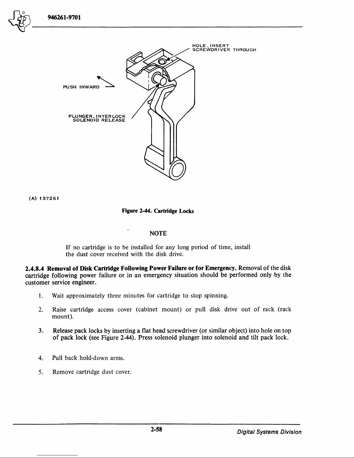
~-------
~
946261-9701
(A)
137261
PUSH
INWAR~
PWNGER, I NTER
LOCK
SOLENOID
RELEASE
Figure 2-44. Cartridge· Locks
NOTE
If
no cartridge
is
to
be installed for any long period
of
time, install
the
dust cover received with the disk drive.
2.4.8.4 Removal
of
Disk Cartridge Following
Power
Failure
or
for
Emergency. Removal
of
the disk
cartridge following power failure
or
in
an
emergency situation should be performed only by the
customer service engineer.
1.
Wait approximately three minutes for cartridge
to
stop spinning.
2. Raise cartridge access cover (cabinet
mount)
or
pull disk drive
out
of
rack (rack
mount).
3. Release pack locks
by
inserting a flat head screwdriver (or similar object) into hole
on
top
of
pack lock (see Figure 2-44). Press solenoid plunger into solenoid
and
tilt pack lock.
4. Pull back hold-down arms.
5.
Remove cartridge dust cover.
2-58
Digital
Systems Division
Page 83

~
946261-9701
~-------
6. Lift cartridge handle, hold cover release
up
and
out
of
cartridge
disk drive
by
button
handle.
to
left,
or
towards
the
center, and lift
7. Place cartridge inside dust cover
that
the cartridge
the center.
8. Close cartridge access door (cabinet
mount).
2.5
SYSTEM OPERATIONAL CHECKOUT
After connecting all cables and applying power
service routine in the computer, perform the following procedure
is
operational.
1.
Install a disk cartridge into the disk drive according
2. Press
3. Ensure
4. Allow disk drive and disk cartridge
5. Load and execute performance demonstration test in accordance with the appropriate
START/STOP
is
illuminated
indicator rotates slowly 90 degrees,
that
20 minutes).
of
section
Model 990 Computer Diagnostics Handbook.
and
dust cover are locked together,
switch
and
that
the
sound
READY indicator
and
fold
mount)
to
to
start
spindle
of
the spindle
then
is
illuminated within
to
down
handle until a
or
slide release
or push disk drive back into rack (rack
the system,
motor.
returns
reach thermal stabilization (approximately
but
to
the procedure in
Observe the
motor
can
to
normal
at
least 70 seconds.
to
snap
is
heard
button
before installing any software
ensure
be heard. Observe
position.
that
the disk system
paragraph
START/STOP
indicating
away
from
2.4.8.2.
indicator
that
brush
6.
If
performance demonstration test
service engineer.
or
any
of
the above steps fails, notify the customer
2-59/2-60
Digital
Systems Division
Page 84

Page 85

"'iY
946261-9701
~-------
SECTION 3
PROGRAMMING
3.1 GENERAL
This section provides information for the
trol words. Paragraphs 3.2, 3.3, and 3.4 provide general information about issuing commands and
interrupts, and about command completion. Paragraph 3.5 describes in detail the contents and formats
of
the eight control words in Figure
Finally, paragraph 3.6 provides hardware and firmware terminology definitions and describes the
data formats that are processed by the disk controller. The programmer should refer
3.6 before attempting to write a software program
formats
3.2 PROGRAMMING
Program
progra..'1lmer
word
modify memory can be used
of
memory addresses.
of
the controller for the disk system.
THE
DISK CONTROLLER
control
is
moved
memory addresses just as any other memory module. The controller can accept eight consecutive
of
the disk system
moves eight words to the disk controller over the TILINE bus in the same way that a
to
the memory
of
the Model 990 Computer. Any computer commands that read
to
communicate with the controller. The controller
progr(L'1lmer
3-1
that are used in programming the disk controller.
is
relatively simple.
to control the disk system using assigned con-
if
he
is
unfamiliar with the terminology and data
To
issue a command
to
the disk system, the
is
assigned a block
to
paragraph
or
The TILINE address for the controller
Figure 2-15. A total
starting TILINE addresses
>F8FO).
3.3 COMMAND CONTROL
The disk controller
CPU) via a set
dresses are shown in Figure
An attempt by the software to write certain bits
assigned a meaning results in a normal cycle with no effect
busy (in a not idle state), any attempt to read
TLTMand for a read cycle, bit zero
mand during a busy cycle, bits 1 through
3.4
The disk controller can be programmed to issue interrupts. This capability is implemented
this disk controller compatible with other disk controllers. The interrupt capability
by having the controller issue an interrupt whenever a mask bit in the controller register
while in the idle mode
has been set.
(TILINE terminate). When the controller
COMMAND COMPLETION
of
16
possible starting TILINE addresses can be selected. The possible range
is
from
is
initiated and interrogated by a TILINE master (normally the computer's
of
control words. These eight control words and their corresponding TILINE ad-
3-1
and described in the following paragraphs.
is
returned as logic zero when the controller
or
by issuing
is
selected by a switch package on the controller as shown in
>FFCOO
an
interrupt upon return
through >FFC78 (CPU addresses >F800 through
of
the disk system hardware register that are not
on
the operation. When the controller
or
write
is
aborted as the controller responds with
is
busy, no
15
are indeterminate (may be either one or zero).
data
transfer occurs for a write cycle;
is
busy. For a read com-
is
implemented
to
idle provided the interrupt enable
to
RO
of
is
make
is
set
3-1
Digital Systems Division
Page 86

'-iY
946261-9701
~-------
CONTROl.
WORD
o
3
CPU
ADDRESS
F800
F802
FB04
F806
TIl.INE
ADDRESS
FF-COO
FFCOI
FFC02
FFC03
FUNCTION
DiSK
STATUS
COMMAND
FORMAT
AND
SEC'T'OR
CYl.INDER
o
OL -OFF-LINE
NR -NOT
o
SPARE
I
o
o
READY
SECTORS
WP -WRITE
US -UNSAFE
4 5 6 7
3
I
TIH
DISK
o
o
o
PER
RECORD
COMMANDS
o
6
PROTECT
o
o
o
o
CYLINDER
a
ATTN(O-3)
(Al.WAYS
ONES)
SI -SEEK
ATTN(N) X ATTMSK(N) ~ INTERRUPT
a
9
SPARE
STORE
o
WRITE
READ
WRITE
READ
WRITE
SEEK
RESTORE
ADDRESS
DATA
UNFORMATTED
(DUMMY -
o
o
o
7 a
INCOMPl.ETE
10
HEAD
I
REGISTERS
FORMAT
DATA
UNFORMATTED
STARTING
II
II
ADDRESS
SEE
SECTOR
12
ATTMSK(O-
12
13
*(SEE
**
(SEE
PARAGRAPH
ADDRESS
14
BELOW)
BELOW)
3.5.2)
15
3)
15
J
15
15
o
BITS
Faoa
4
FF'CQ4
COUIIIT
(BITS
0-14 = WORD
0-15 • EVEN
BYTE
COUNT
COUNT)
o
FaOA
6
Faoc
F80E
FFC05
FFC06
FFC07
'"
*
REGISTERS
'"
HEADER
ADDRESS
SEl.ECT
AND
MSB
ADDRESS
CONTROl.L.ER
STATUS
STORE
DATA
FORMAT
FORMAT
MEMORY
ADDRESS
o
SPARE
o
ERR -ERROR
INT -INTERRUPT
AC -ABNORMAl.
0
0 7 8
0
TRACKS/CYLINDER
0
HEAD
0
0
3 4
4
ENABL.E
COMPLETION
SECTORSfTRACK
SECTORS;RECORD
UNIT
SEL.
o I 2 3
DE -DATA
TT -TIl.INE
IE -10
4 5
0
1
4
S
RECORD
WORDS
7 8
7
ERROR
ERROR
PER
7 8
WORD
TIMEOUT
TRACK
COUNT
(l.SB)
10
SPARE
CT -COMMAND
SE -SEARCH
UE -UNIT
OVERHEAD/RECORD
CYl.INDERNNIT
CYl.INDER
SECTOR
11
ERROR
ADDRESS
M
EMORY
12
ERROR
TIMER
(MSB)
ADDRESS
15
15
15
15
15
I
15
I
15
15
I
15
(8)132878
Figure 3-1.
Model
OSlO
Disk
System Control
3-2
Word
Formats
Digital
Systems Division
Page 87

Jd1s\
_______
_
~
946261-9701
3.4.1
COMMAND
COMPLETION
WITHOUT
INTERRUPTS.
If
interrupts are
not
used, the
computer program can determine
if
the controller has completed a command by reading bit 0
of
control word 7.
If
bit 0 (idle) is zero, the disk controller
is
busy. When a command
is
complete, the
idle bit
and
either the error bit
or
the complete bit
is
set.
If
lockout
is
being used, it is set after con-
trol word 7
is
read,
and
if
the error bit was set,
an
error status bit
is
set.
3.4.2
COMMAND
COMPLETION
WITH
INTERRUPTS.
The controller issues two kinds
of
in-
terrupts
to
the computer. One interrupt
is
issued when the controller completes a command,
and
one
when the disk
is
issued a seek
or
restore command (interrupt given immediately after return
to
idle
state with interrupt mask bit set).
3.4.2.1
Command
Completion Interrupts. In order
to
have the controller signal the completion
of
a
command by issuing
an
interrupt
to
the computer, the computer program sets the interrupt bit
of
control word 7 (bit
3)
at
the same time the command
is
started by resetting the idle bit (bit
O).
When
the controller returns
to
idle,
an
interrupt is issued when the controller detects either the complete
or
error bit set with interrupt enabled. The interrupt
is
cleared by resetting interrupt enable in R7.
3.4.2.2
Seek
and
Restore Completion Interrupts. Control word 0 contains four attention bits
and
four attention mask bits. The attention bits are
not
used by this disk controller. They are, instead,
forced
to
logic one whenever register
RO
is read. The programmer can set
or
reset the mask bits by
using any
of
the computer memory instructions.
The correct way
to
use the control word 0 interrupts
is
to
issue the seek
or
restore command
to
the
controller; then, after the controller reports completion, set the correct mask bit. When the disk
drive finished the dummy seek operation,
an
interupt
is
issued
to
the computer. The interrupt can
then be cleared by resetting the mask bit. The
TILINE
interrupt
is
always reset when the controller
goes from
an
idle
to
a busy condition. The controller will
not
execute
an
independent seek com-
mand.
It
accepts the command, goes through initialization
and
self diagnostics, then terminates with
operation complete so
that
interrupts are handled the same.
3.5
CONTROL
WORD
CONTENT
AND
FORMATS
The eight control words shown in Figure 3-1 are used
by
the programmer
to
direct the activities
of
the disk drive. The format, content,
and
activities
of
each
of
these control words are described in the
following paragraphs.
3.5.1
DISK STATUS,
CONTROL
WORD
O.
When the controller is
not
busy, the disk status
of
control word 0 can be used. Figure 3-2 shows the bits
of
control word 0 (disk status).
Bits
0 through 5
of
control word 0 contain individual status indicators from the selected disk drive.
Bits 8 through
11
are forced
to
logic
1.
The bits are defined as follows.
Bit
0,
Ojjline (OL). When bit 0 is set, it indicates
that
there is
no
power
to
the selected disk drive, the
drive is
not
at
the proper speed,
or
not
loaded with a disk cartridge,
or
that
an
unsafe condition
exists.
o 2
3
4
5 6
7
8
11
12
15
OL
NR
WP
US
SPARE
SI
SPARE
1
1 1 1
ATTN
INTERRUPT
MASK
(0-3)
(A)
133992A
Figure 3-2. Control
Word
0
3-3
Digital
Systems Division
Page 88

~-------
~
946261-9701
o
2
3
4
5
6
7
8
9
10
1 1
12
13 14
15
0
0
0
0
TIH
DISK
SPARE
HEAD/SURFACE ADDRESS
COMMANDS
(A)
133993
Figure 3-3. Control Word 1
Bit
1,
Not
Ready (NRJ. When bit 1
is
set,
it
indicates
that
the selected disk drive
is
in the process
of
performing a seek operation, or
that
the heads are
not
loaded.
Bit 2, Write Protect (WP). When bit 2
is
set, it indicates
that
the write protect status
(WRITE/PROTECT
CART
switch
or
WRITE/PROTECT
FIXED
switch)
of
the selected disk
drive
is
on.
When
this switch
is
on,
it inhibits
the
write logic within the disk drive.
Bit 3, Unsafe (US).
When
bit 3 is set,
it
indicates
that
the
selected disk drive
is
unsafe. This means
that
the safety circuits
that
protect the recorded
information
are unsafe,
and
the unsafe condition
must
be
removed before any more commands
are
attempted.
If
an
unsafe condition occurs, the
F
AUL
T switch
on
the selected disk drive
can
be
used
to
clear
the
fault condition provided the condi-
tion has ceased.
A restore
command
can also be issued
to
clear the fault condition.
Bit 5, Seek Incomplete (SI).
When
bit 5
is
set,
it
indicates
that
the selected disk drive has failed
to
complete a seek
operation
because
of
a disk malfunction
or
detection
of
an
illegal cylinder address
(illegal address interlock).
When
this status
is
detected, the software must initiate a restore com-
mand
before attempting
to
execute any
other
command.
Bits 8 through 11. Bits 8 through
11
are
not
used and are forced
to
logic 1 because overlapped
seeking
of
logical units
is
prohibited.
Bits 12 through 15, Attention Interrupt Mask
(0-3).
These bits cause
an
interrupt when set
to
logic
1.
The
TILINE
interrupt is set when the
attention
interrupt
mask
is
on
and
the controller
is
idle. Soft-
ware can disable
the
interrupt source
by
clearing the interrupt mask bits.
3.5.2
COMMAND
CONTROL,
CONTROL
"'ORD
1.
Control
Word
1 is used for disk cOllunands
and
surface selection. Figure 3-3 shows
the
bits
of
control
word 1.
The
bits
of
control word 1 are
defined as follows:
Bit
4,
Transfer Inhibit (TIH). When bit 4 is set,
the
controller will
not
transfer any disk words
into
memory when a read
data
command
is specified.
The
purpose
of
this
bit
is
to
allow
data
verification
by
relying
on
the
cyclical redundancy character (CRC) check without having
to
provide a
buffer
in
memory for
the
specified block.
After
the read
data
command
is completed, this bit
is
reset
by
the
computer.
Bits 5 through
7,
Command. These three bits are a 3-bit code
that
designates a
command
(one
of
the
eight commands illustrated in Figure 3-1).
The
bits
and
the
commands
they specify are listed in
Table
3-1
and
described as follows:
NOTE
Details
of
the contents, format, and programming procedures for
the disk commands are provided later in this section. Refer
to
paragraph 3.5.9.
3-4
Digital
Systems Division
Page 89

~~------------------
~
946261-9701
Table 3-1. Disk Command Bits
Bits
567
Command
000
Store Registers
001
Write Format
010
Read Data
o 1 1
Write Data
100
Unformat Read
101
Unformat Write
1 1 0
Seek
III
Restore
• Store Registers (000) - Used
to
ascertain which disk drive
is
connected
to
the
controller
and
to
establish parameters
for
the
particular disk.
• Write
Format
(00 1) - Used for formatting
or
reformatting a single track.
• Read Data (0 1
0)
- Reads formatted
data
from disk and transfers the
data
to
the
specified TILINE address.
• Write Data (0 11) - Transfers data from a TILINE address and controls formatted
data
being written
on
disk.
• Unformat Read (100) - Reads data from disk
without
regard
to
record
ID
or
record
boundaries and transfers the data
to
the specified TILINE address.
• Unformat Write
(10
1) - Transfers
data
from a TILINE address and writes the data on
the disk
without
regard
to
record boundaries.
• Seek (110) - Dummy command
that
is accepted and completed normally
but
does
not
actually move heads.
• Restore (111)
-:-
Positions the head over cylinder
O.
A restore
is
implemented by a full
stroke movement by disk.
Bits 8
and
9.
Bits 8 and 9 are
not
used and are forced
to
logic
O.
Bits
10
through 15, Head Address. The field consisting
of
bits 10 through
15
selects one
of
the
two read/write heads.
3.5.3
FORMAT
AND
SECTOR,
CONTROL
WORD
2.
Control
word 2 is
used
to
indicate
the
number
of
sectors
per
record
and
the
address
of
the
sector.
The
bits
of
this
control
word are shown
in Figure 3-4
and
defined as follows:
Bits
0 through
7,
Sectors Per Record. A disk can be formatted
into
variable length
data
records
with a fixed number
of
sectors
per
record for a given track. Bits 0 through 7
of
Control Word 2
specify the number
of
sectors per record. The
number
of
sectors
per
record multiplied by
the
number
of
records
per
track will
not
exceed
the
fixed
number
of
sectors per track
of
a particular
disk drive.
Format
calculations are given in paragraph 3.6.1.
3-5
Digital
Systems Division
Page 90

~-------
"iY
946261-9701
o
7 8
15
SECTORS
PER
RECORD
SECTOR
NU
MBER
ADDRESS
(A)
133994
Figure 3-4. Control
Word
2
o
15
CYLI
NDER
ADDRESS
(A)
133995
Figure 3-5. Control Word 3
o
14
15
BITS
0-14
=
WORD
COUNT
(BI
TS
0-15
=
EVEN
BYTE
COUNT)
o
(A)
133996
Figure 3-6. Control
Word
4
Bits 8 through
15,
Sector Address. This field selects the sector number at which the controller starts
a read
or
write operation. The controller adds the sectors per record (bits 0 through
7)
to the starting
record address to calculate the address
of
subsequent
data
records
on
a track when multiple records
are transferred. The range
of
sector addresses
is
>00 through >13.
NOTE
If
the sectors per record for a track does
not
equal one, then the
programmer must be sure that sector addresses that correspond to
record boundaries are used.
A sector address larger than the maximum sector address results in a timeout status because the controller cannot find a starting sector number
at
which to start executing the command. A sectors per
record command exceeding maximum sector size will be detected
on
initialization
and
will cause the
controller
to
trap
to
command timeout status.
3.5.4
CYLINDERS,CONTROI
..
WORD 3. The cylinder address
is
selected by bits 0 through
15
of
control word 3. Figure
3-5
illustrates control word 3. The valid number range
is
>0000 through
>0197.
An
invalid cylinder address results in a termination
and
unit error controller status being set.
The disk status (control word
0)
will indicate seek incomplete.
3.5.5 WORD COUNT, CONTROL WORD 4. The word count
is
controlled by control word 4 as
shown in Figure 3-6.
For
data
commands, this field selects the number
of
16-bit
data
words
to
be
transferred between the disk
and
the TILINE. The number
of
words
is
limited by the available
TILINE
memory and the disk memory from the starting disk address
to
the last sector
of
the last
3-6
Digital Systems Division
Page 91

Ja75\
______
_
~
946261-9701
o
14
15
LSB
MEMORY
ADDRESS
(A)
133997
Figure 3-7. Control
Word
5
o 4
7 8
10
11
15
SPARE
UNIT
SELECT
SPARE
MSBS
MEMORY
ADDRESS
(A)
133998
Figure 3-8. Control
Word
6
track.
An
attempt to transfer from a nonexistent TILINE memory results in a TILINE timeout
status for the controller. For a write command, this field specifies the record word count.
3.5.6
LSD
MEMORY ADDRESS, CONTROL WORD 5. The least significant bit (LSB) memory
address
is
determined by control word 5 (Figure 3-7).
By
the use
of
this control word, the software
selects the
15
least significant bits (LSB)
of
the TILINE memory address for the starting address
of
a
data transfer. The controller fetches or stores data through the TILINE bus at sequential addresses
until the word count decrements to zero. The
CPU byte selection bit (bit
15)
is
ignored by the
controller.
3.5.7
UNIT SELECT AND
MSD
MEMORY ADDRESS, CONTROL WORD 6. The disk drive
selected and most significant bit
(MSB) memory address are specified by control word 6 (Figure
3-8). Bits
0 through 3 and 8 through
11
of
this field are not used.
Bits 4 through
7,
Unit Select Field. The value
of
this field
is
used to select one
of
four disks (one
fixed and one cartridge for each
of
two disk drives) attached to the disk controller. Only one disk
drive can be selected at a time, as follows:
Bit 4 - Disk drive
0,
fixed disk
Bit 5 - Disk drive
0,
cartridge disk
Bit 6 -
Disk
drive
1,
fixed disk
Bit 7 - Disk drive
1,
cartridge disk.
Bits
11
through
15,
MSB
Memory Address. This field selects the five most significant bits
of
the
TILINE memory address. These 5 bits are concatenated to the
15
LSB
memory address bits
of
con-
trol word 5 to complete the
20-bit TILINE address.
3-7
Digital Systems Division
Page 92

~-------
~
946261-9701
o 2 3
4
5
6 7
8
9
n
0
I.
4
4
SPARE
AC
ME
DE
IDLE
ERROR
LOCK
OUT
COMPLETE
INTERRUPT
ENABLE
AC-ABNORMAL
COMPLETION
ME-MEMORY
ERROR
DE-DATA
ERROR
(A)
133999
TT-
TiLl
NE
TI
MEOUT
IE-tO
ERROR
RE-RATE
ERROR
Figure 3-9. Control
Word
7
10
11
12
13
14
15
TT
IE
RE
CT
SE
CT-COMMANO
TIMER
SE-SEARCH
ERROR
UE-UN t TERROR
UE
3.5.8 INTERRUPT AND CONTROLLER STATUS, CONTROL WORD 7. The interrupt and
controller status field, shown in Figure 3-9, provides error information and controller status information to the TILINE bus. Bits
0 through 4 are used primarily to report controller completion and
error information; bits 7 through
15
are used to convey the error status information about the con-
troller. The individual bits and their functions are described
as
follows.
Bit
0,
Idle. Bit 0
is
logic zero when the controller
is
busy (performing a sequence, etc.). The software
clears bit
0 to activate the disk controller to start execution
of
the command bits (bits 5 through
7)
of
control word
1.
When a command
is
successfully completed or terminated because
of
an error con-
dition, the disk controller sets bit
0 to logic
1.
At the same time, the controller sets bit 1
of
this field
for a successful completion, or sets bit 2 if the operation
is
terminated as the result
of
an error
condition.
Bit
1,
Complete.
Bit 1 is
set when a command
is
completed without encountering
an
error. The
bit may be reset by the software when servicing the interrupt.
Bit
2,
Error. Bit 2
is
set by the controller when
an
operation
is
terminated
as
the result
of
an
error condition. This bit may
be
reset by software when servicing the interrupt or the status that
was
generated.
Bit 3, Interrupt. Bit 3 enables the controller interrupt when the complete bit (bit
1)
or the error bit
(bit
2)
is
set. This interrupt enable does not affect the unit attention interrupts which are controlled
by the attention mask
of
control word
o.
Bit
4,
Lockout. Bit 4
is
set to logic 1 by the controller when control word 7
is
read while the con-
troller
is
idle. This bit
is
intended for use with multiprocessor systems.
Bits 5
and 6 are
not
used.
Bits 7 through 15, Controller Status. Bits 7 through
15
of
control word 7 are controller status bits
that represent the status
of
the controller after a command has been executed. The bits contain valid
information when the error bit (bit
2)
is
set. A special case exists when a self-diagnostic error
is
detected. When a self-test error occurs, all error status bits
of
R7
(bits 7 through
15)
are set.
Bit
7,
Abnormal Completion Error (AC). Bit 7
is
set if a disk operation
is
terminated because
an
I/O Reset, Power Failure Warning, or Master Power Reset
was
detected
on
the TILINE bus. (This
bit
is
set when the disk
is
powered up.)
3-8
Digital
Systems Division
Page 93

Jd7~
______
_
~
946261-9701
Bit
8,
TILINE
Memory Error (ME). This bit
is
set after completion
of
one
of
three disk commands:
write data, write format,
or
unformatted write, when it has been determined
that
a memory error
occurred during the time
that
data
was being transferred from the
TILINE
bus
to
the disk con-
troller. (This
is
normally a parity error.)
Bit
9, Data Error (DE). This bit
is
set during a disk read operation
if
any
of
the calculated check
characters (cyclic redundancy characters
or
CRC) does
not
match the check character read from the
disk
data
record(s). This means the
CRC
did
not
compare because
of
a parity error
on
the disk. All
data
transfer operations are terminated after a
data
error
is
encountered.
Bit
10,
TILINE
Timeout Error (TT). This bit is set
if
the controller addresses a nonexistent memory
address
or
a slave fails
to
respond.
TILINE
timeout causes command termination.
The
timeout
period
is
10
± 2 microseconds from the time master-device active (MDACT)
is
selected.
Bit
11,
ID
Word Error (IE). This bit is set when
an
ID word comparison error occurs during the ID
verification
of
a read
data
or
write
data
command. Verification includes comparison
of
ID words 1
and 2 and
CRC checking
of
the three words. One hardware retry is attempted
if
an
ID error occurs.
If
the retry fails, the command
is
aborted
and
error status
is
aborted.
Bit
12, Rate Error (RE). This bit
is
set when a timing error
is
encountered in the transfer
of
data between the TILINE master control and the disk interface:
1.
During a read operation, the disk interface exceeds the capacity
of
the data buffer.
The controller did
not
transfer the previous word across the TILINE before the next
word
is
assembled with the buffer being full.
2.
During a write operation, the disk interface empties the data buffer before completing
the writing
of
a data sector.
Bit 13, Command Timer Timeout (CT). This bit
is
set when the 200 ±20 millisecond command
timer expires before an operation
is
completed. The timer acts
as
a dead-man timer which
is
reset
when the controller reenters the IDLE loop.
Bit
14, Search Error (SE). Bit
14
is
set when the controller does
not
detect a sync character (>6E)
within one physical sector while attempting
to
read from the disk. Microcode attempts one retry
before commanding abortion.
Bit
15, Unit Error (UE). The unit error status bit (bit
15)
is
set when
an
operation is terminated
because
of
a disk drive error. The disk status register
can
be examined by software
to
determine the
cause
of
the unit error. The following may cause a unit error:
a.
Unit
not
ready
b.
Unit off-line
c.
Unit unsafe
d.
Seek incomplete
e.
Write operation
is
attempted on write-protected unit.
3-9
Digital Systems Division
Page 94

4tJ
946261-9701
0
2 3 4
5 6 7 8 9
10
1 1
12 13
14
15
I
SPARE
I
SPARE
I
TlH
DISK
COMMANDS
SPARE
I
HEAD
ADDRESS
I
0 0 0
STORE
REGISTERS
0 0
1
WRITE
FORMAT
0
1 0
READ
DATA
0 1
WRITE
DATA
1
0 0
READ
UNFORMATTED
0
1
WRITE
UNFORMATTED
1
0
SEEK
1
RESTORE
(A)
134000
Figure 3-10. Command Format
3.5.9 DISK COMMANDS.
As
previously explained, disk commands are specified by bits
5,
6,
and
7
of
control word
1.
The values
of
these bits provide the eight disk commands listed in Figure 3-10.
These disk commands are described in the following paragraphs.
3.5.9.1
Store Registers Command. The store registers command causes the controller to store up to
three words starting at the specified TILINE address.
As
shown in Figure 3-11, the three words con-
tain the following information.
Word 1 - This word contains the total number
of
formatted words that can be recorded on a disk
track. The number
is
3840
10
=
OF00
16
.
Word 2 - This word contains the sectors per track and the number
of
words
of
overhead per
record parameters to be used in the calculations
of
the format parameters. Bits 8 through
15
of
this word specify the overhead per record. This number
is
equal to 48
10
= 30
16
for the disk drive.
Bits
0 through 7
of
this word specify the number
of
sectors per track, which
is
20
10
=
14
16
.
Word 3 - This word contains the number
of
tracks per cylinder and the number
of
cylinders per
disk,
as follows:
Item
Bits
Tracks/cylinder
0-4
02
10 = 02
16
Cylinders/
disk
5-15
408
10
= 198
16
Composite
0-15
1198
16
An example
of
list words for a store registers command
is
given in Table 3-2.
3.5.9.2 Write Format Command. The write format command
is
used for formatting a new disk or
for reformatting an existing disk.
One complete track
is
formatted per command. An example
of
a
write format command
is
given in Table 3-3.
After initialization, the controller checks for unit errors by examining the disk status (offline not
ready, unsafe, write protect, seek incomplete): seeks to the specified cylinder: and sets the specified
head address. The controller assembles the ID words from its internal registers and counters and
records the word(s) on the disk at the specified disk track address
as
shown in Figure 3-12. The controller records the data field following the ID words with the data word in the specified TILINE address repeated for all data word positions.
3-10
Digital Systems Division
Page 95

~
946261-9701
~-------
Word
0
2
3
4
5
6
7
Note:
Word
0
1 A
after
set.
Table 3-2. Example
Data
0000
0000
0000
0000
0006
1000
0800
0800
unit
does
not
the
command
Data
0000
oi
List Words in a Store Registers Command
Clears the disk status
Command
Not used
Not used
Three words
Put
three
words
1
Unit 0
Set
lockout.
have
to
is
complete
Table 3-3. Write Format
be
selected,
Reset
will
into
idle
but
have
Comments
memory
and
all
if
no
unit
the
not
starting
status
is selected,
ready
and
Command
Comments
at
bits
off
TILINE
the
disk
line
status
address
status
bits
>00800
0101
2
3
4
5
6
7
0300
OOCA
03D8
1000
0800
1800
o
o
SECTORS/TRACK
o
TRACKS/CYL
The
command
The
record
Cylinder
Word
Memory address
Unit 0
Use
4
address
count
interrupts
WORDS
5
is bits 5
will
be
= Max. for 3 sectors/record
and
through
three
sectors
selected is
leave
lockout
PER
TRACK
8
7
7;
the
long.
>CA
set
CYLINDER/UNIT
surface
The
OVERHEAD/RECORD
address
sector
address
is = 1
is
zero
(0000)
15
15
15
(A)
134001
Figure 3-11. Store Registers Data
3-11
Format
Digital Systems Division
Page 96

~
946261-9701
~-------
4
o
5
15
o
o
(A)
134002
HEAD
SEC
8
7
TOR
5;
RECORD
WORD
Figure 3-12. Header Data Format
Table 3-4. Example
Word Data
0 0000 Clear the disk status
1
2
3 0000 Cylinder 0
4
5
6
7
0200
0300
2000
0000
021F
0
COUNT
Read surface 0
3 sectors/record, start on sector 0
1000
words
TILINE
Unit 2
Do
not
use interrupts or lockout
CYLINDER
of
Read Data
Comments
memory
SECTOR
address
15
ADDRESS
15
= >F8000
Note:
In
this example, the format
be 3 sectors per record or an error
of
all
of
the tracks read must
will be flagged.
The controller formats each record on the track with ID words, data, and the required gaps. Only
the start
of
each record has the ID word written. When a record
is
longer than one sector, the con-
troller writes across sector boundaries allowing more words to be packed into sectors than normally
of
possible at one sector per record. The value
control word 4.
the record word count (ID word
0
3.5.9.3 Read Data Command. The read data command specifies the number
will be transferred from the specified disk address to the specified TILINE address. An example
is
read data command
given in Table 3-4.
3)
is
specified by
of
16-bit words that
of
a
After initialization, the controller checks for unit errors by examining disk status (offline, not ready,
unsafe, seek incomplete); seeks to the specified cylinder; searches for the desired sector address;
reads the ID words at that address; verifies the contents
ID wqrd
3;
verifies the CRC character
of
the ID words; waits the specified time; and looks for a sync
ID words 1 and
2;
stores the contents
of
of
character. After detecting the sync character, 16-bit words from the data field are assembled and
is
transferred to the specified TILINE addresses (if transfer inhibit
not specified).
3-12
Digital Systems Division
Page 97

~
946261-9701
~-------
A failure to verify an ID word results in an ID error status (bit
operation. When the controller encounters the end
count
is
nonzero~
of
the track if it exists. The new record ID
When
of
continues to read data from the disk until the end-of-record
character can be checked before loading status.
When
nonzero, the controller automatically increments the head address
words for the first sector (00)
contents
character and continues reading data from disk and again begins transferring data over the
TILINE bus.
the remaining transfer word count
a record, then the controller discontinues transmitting data words across the TILINE bus
the controller encounters the end
of
When the controller encounters the end
nonzero, the controller automatically seeks to the next cylinder; selects head address zero for the
new track; reads the ID words for sector
contents
and continues to read words from the disk and transfer them to the TILINE bus
not specified.
will
address interlock
of
terminate with unit error and the resultant unit error
the controller automatically continues reading data on the next sequential record
is
checked before continuation
is
zero but the controller has not encountered the end
of
of
that track; verifies the contents
10 word 3; verifies the
ID word
If
3;
verifies the
the end-of-cylinder occurs, and the remaining word count
ORed with seek incomplete.
eRe
character following the
of
a cylinder, and the remaining transfer word count
00; verifies the contents
eRe
character following the ID words; looks for sync character
of
a record but the remaining transfer word
a track and the remaInlng transfer word count
11)
and termination
of
is
encountered so that the
to
the next track; reads the
of
10
words 1 and 2; stores the
10
words; looks for sync
of
ID words 1 and
is
nonzero, the operation
will
be seek incomplete caused by illegal
of
the read data
data gathering.
2;
if
transfer inhibit
but
eRe
is
ID
is
stores the
is
3.5.9.4 Write Data Command. For a write data command the controller transfers the number
specified 16-bit words from the specified TILINE addresses to the specified disk addresses. After
initialization, the controller checks for unit errors by examining disk status (offline, not ready, unsafe, write protect, seek incomplete); seeks to the specified cylinder; searches for the desired sector
address; reads the ID words; verifies ID words 1 and
the
eRe
character following the ID words.
write mode and, after a specified delay, starts writing a sync character and data on the disk.
ID words fail to compare, the operation
is
Data
minate condition
number
tial record starts
record plus the number
When
remainder
The controller compares the
disk at the specified sector address.
written on the disk until the specified number
is
encountered. When the number
of
words per record, the controller continues to the next sequential record. The next sequen-
at
the sector number whose value
of
sectors per record.
the transfer word count
of
the record with zeros until the record word count has been decremented to zero.
is
10 words from its internal registers with the 10 words read from
If
is
terminated with an ID status error.
less
than the record word count, the controller
If
the
10
2;
stores the contents
the ID words compare, the controller switches to the
of
words has been transferred unless a ter-
of
words to be transferred
is
equal to the beginning sector number
words are identical, the
of
ID word
eRe
3;
and verifies
is
greater than the
of
character
is
of
If
the
the last
fills
the
checked.
3-13
Digital Systems Division
Page 98

"'iY
946261-9701
~-------
Table 3-5. Read Unformatted Command Example
Read Unformatted Command
Word
Data
Comments
If
the
eRe
character
0
2
3
4
5
6
7
Word
0
2
3
is
0000
0400
0001
0000
0008
1000
0400
1800
Data Received from Command
Data
0000
0101
0002
SF SF
of
the proper value, the controller switches to the write mode and begins
writing data. After the last data word
character that pertains to the data.
of
written only at the start
each record.
ID
Unformatted read
Sector/record
Cylinder 0
410
words
TILINE
Unit
= 1
Use
interrupts
Track 0
Sector/record = 1, sector:;:: 1
4 bytes, 2 words
Cyclic Redundancy Character
of
the sector
not
memory
and
Comments
is
used. Sector address = 1
address
lockout
= >00800
(CRC)
written, the controller records the
eRe
words are not written for each sector on the disk, but are
When
the controller encounters the end
is
count
starts reading
ID
nonzero, the controller automatically increments the head address to the next track;
ID
of
sector zero; verifies the contents
word 3; verifies the
eRe
character following the
of
a track for a cylinder and the remaining transfer word
of
ID
words I and 2; stores the contents
ID
words; and continues the write operation
of
after the appropriate delay,
When
the controller encounters the end
of
a cylinder, and the remaining transfer word count
is
nonzero, the controller automatically seeks to the next cylinder; selects head address zero for the
new track; starts reading the
for sector zero; verifies the
ID
words; and continues the write
ID
operation at sector zero.
3.5.9.5 Read Unformatted Command. Starting at the specified disk address, a read unformatted
of
command transfers the specified number
dresses. The read unformatted command
tion to sector boundaries and does not read IDs. An example
the data received from the command
16-bit words from the disk to the specified TILINE ad-
is
used primarily for diagnostics and does not pay atten-
of
a read unformatted command and
is
given in Table
3-5.
After initialization, the controller checks for unit errors by examining disk status (offline, not ready,
unsafe, seek incomplete); seeks to the proper cylinder; and starts transferring data to the TILINE
of
after the sync
the specified sector address
secutive information, without regard to end-of-record
is
detected. The controller continues to read all con-
or
end-of-track boundaries, until the
3-14
Digital Systems Division
Page 99

~-------
'i::Y
946261·9701
specified number
of
words has been transferred
or
until a termination condition
is
encountered. A
check for the
eRe
is
performed at the end
of
the operation, and a data error status
is
reported
is
the
eRe
is
not correct. This allows for error detection after the ID words
if
three words (six bytes) are
specified in the word count.
3.5.9.6 Unformatted Write Command.
An
unformatted write command transfers the 16-bit words
from the specified TILINE address to the specified disk address. Basically, the controller locates the
proper sector and writes the specified bytes.
After initialization, the controller seeks to the specified cylinder and starts writing data on the
disk after the sector mark
of
the specified sector address
is
detected and the correct lead
gap
has
been generated. The controller continues to write
all
consecutive information, without regard to
existing record boundaries, until the specified number
of
words has been transferred
or
until a
termination condition
is
encountered. The controller adds a sync character
to
the beginning
of
the data and a CRC character at the end.
3.5.9.7
Seek Command. The seek command causes the disk controller to implement initialization
and run a short diagnostic self-test. The command does not issue the
new
cylinder address to the
disk drive. Instead, the command executes to termination and completes normally if no error conditions are detected. The actual seek
is
not performed because the heads for the fixed and removable
disks move together as a unit on the same head carriage assembly. Independent seeks that would be
issued in the overlapped mode between the two head assemblies are a physical impossibility.
By
issuing the command but not issuing it to the disk drive, the software command structure remains
compatible with other disk systems.
If
the interrupt mask
is
used to set an interrupt, the mask bit must not be set until after the com-
mand
is
issued. Otherwise, an interrupt occurs immediately. The interrupts are cleared by clearing
the attention mask in the controller. Interrupts can also be set by setting the interrupt enable bit in
R7.
Upon completion, the controller sets an interupt and holds it until the computer clears the inter-
rupt enable bit in the controller. Table
3-6
is
an example
of
a seek command.
3.5.9.8 Restore Command. The restore command
is
required if a seek incomplete disk status
is
detected by software or if an unsafe disk status occurs. The restore command positions the heads
of
the selected disk drive over cylinder zero.
Table 3-6. Example
of
a Seek Command
Word
Data Comments
0
0000
0600
Seek surface
is
not
used
2
0000
Sector/record and sector and address are not used
3
0003
Cylinder = 3
4
0000
Word count
is
not
used
5
0000
Memory address
is
not
used
6
0100
Unit = 3
7
1800
Use
controller interrupts and lockout
3-15
Digital Systems Division
Page 100

~-------
~
946261-9701
Before issuing the restore command, the offline status is checked.
If
the drive is offline, the restore
command
is aborted
and
the unit error status in R7 is set.
If
the drive
is
online, the restore command
is issued
to
the drive
and
the controller executes a O.S-second delay loop. Following the delay, the
controller issues
an
interrupt
to
the computer
if
either the interrupt bit is set
or
one
of
the attention
mask bits is set. Overlapped restores are
not
allowed between the fixed
and
cartridge disks because
the
heads are attached
to
the same carriage assembly
and
move together as a unit.
3.6
FORMATS AND DEFINITIONS
This paragraph gives the formats
of
the data written on the disk surfaces in a drive and a defi-
nition
of
hardware and firmware terms
as
related
to
software programming.
3.6.1 DEFINITION
OF
TERMS.
Disk Cartridge - A disk cartridge consists
of
one
disk
mounted
on
a hub. Refer
to
Figure 3-13.
Read/Write Heads -
The
four
read/write
heads (0
through
3) are mechanically locked
to
the car-
riage assembly
and
fly
on
an
air
boundary
close
to
the recording surface, so the heads never actually
contact
the
rotating disk surfaces
in
normal operation.
Disk Recording Surfaces - There are two
data
recording surfaces in a disk cartridge; the
recording zone
on
each surface consists
of
a maximum
of
408 cylinders.
Recording Tracks - A recording track consists
of
the
recording area
on
a disk
that
includes the en-
tire circumference
of
the cartridge.
The
track is subdivided by sector marks generated by the disk
drive. Sector zero starts
at
the first sector
mark
that
occurs after the time
of
the first index
mark.
The
index signal is
not
used by the OSlO disk system.
Sectors are linked together
to
make records. Data
is
written continuously over sector boundaries
for multiple sectors per record.
Data Word - A data word on the disk
is
16 bits long. The number
of
data words in a record
is
selectable by
the
programmer
up
to
a maximum number. To find the maximum
number
of
words in one record, use the following formula:
Total words/track - [(Number records/track) X overhead]
Max. words per record
= /
Number records track
See paragraph 3.5.9.1 for parameters.
Sector - Each track is divided
into
20 sectors. The format
of
data recorded on a track consists
of
records
of
equal length which are separated
by
gaps. Gaps are automatically inserted
by
the
controller
to
ensure reliable data recovery
at
each sector address over the range
of
operating
temperatures and from recorded media exchanged between disk systems
of
the same type.
Record - The record size is variable
but
it must be
one
or
more sectors,
up
to
one
track in length.
The
programmer can select the
format
of
a track
by
setting the sectors/record parameter in bits 0
through 7 of
command word 2. A sector
mark
defines the beginning
of
a physical record.
Data
is
written across sector gaps
if
a record size greater
than
one is selected.
3.6.2·
SECTOR
FORMAT.
A sector is a continuous recorded bit stream
on
a disk track which starts
at
a unique sector mark. A sector contains the fields shown in Figure 3-13. These fields are described
in the following paragraphs.
3-16
Digital Systems Division
 Loading...