

Page 1
C2000™ Systems Applications Collateral
DRV8412 Digital Motor Control Kit Quick Start Guide
Jan 2011
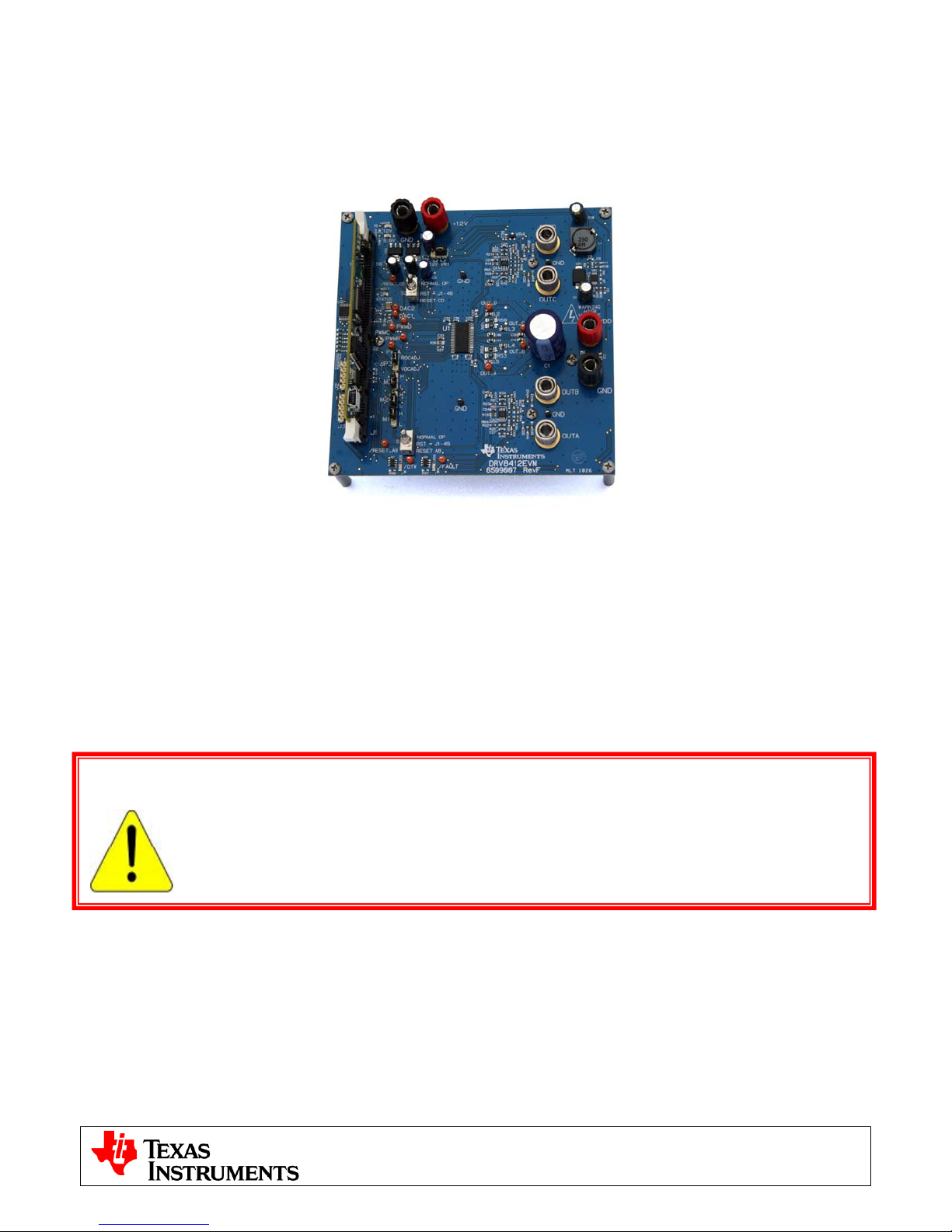
Fig1: DRV8412-C2-KIT
The DRV8412 Digital Motor Control (DMC) kit (DRV8412-C2-KIT), provides a great way to learn and experiment
with digital control of Brushed DC and Stepper motors.
The DRV8412 Digital Motor Control Kit contains:
• F28035 controlCARD
• DRV8412 DMC board with slot for the controlCARD
• 2 brushed DC motors, 8-wire bi-polar stepper motor
• 24V 2.5A DC Power Adapter
• USB Cable, USB Stick with Quick Start GUI, Guide, and links to install controlSUITE (which includes all
documentation and source code) and CCStudio Integrated Development Environment
WARNING
This EVM should be used only by qualified engineers and technicians who are familiar with
the risks associated with handling electrical and mechanical components, systems and
subsystems. The EVM operates at voltages and currents that can result in electrical shock,
fire hazard and/or personal injury if not properly handled or applied. Users must use the
equipment with necessary caution and employ appropriate safeguards to avoid serious
injury. Users must not touch any part of the EVM while energized.
Features of the DRV8412 Motor Control Board:
o Dual H-Bridge Power Stage capable of stepper motor control, dual brushed DC motor control
or control of a single larger DC motor with a parallel H-bridge configuration. 52.5V DC max input
voltage and 6A* maximum current in the configuration shipped.
o Aux Power Supply Module 12V control voltage can be supplied externally or from DC bus.
o Isolated SCI & JTAG
o Quadrature Encoder Interface
o Two PWM DAC’s to observe the system variables on an oscilloscope.
o Hardware Developer’s Package which includes schematics & bill of materials.
o Open source software available through controlSUITE
1
v2.0
Page 2
C2000™ Systems Applications Collateral
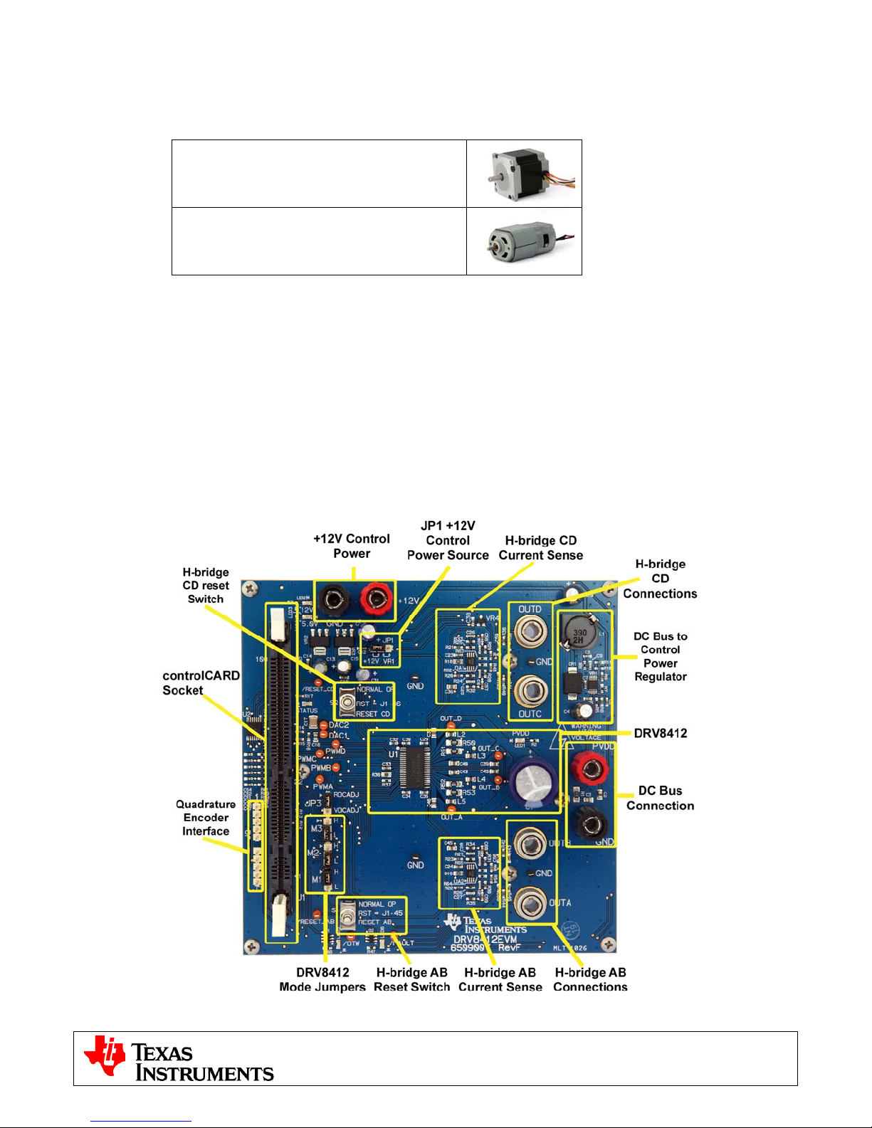
The software available with the kit is pre-optimized for the included motors. The software is open source, and
can be modified to tune and run a different motor. The following motors are available with the kit:
Bi-polar Stepper Motor
(4.2A/phase (parallel) , 8-wire, 1.8°/step)
Brushed DC Motor
(6-24V, 0.92A)
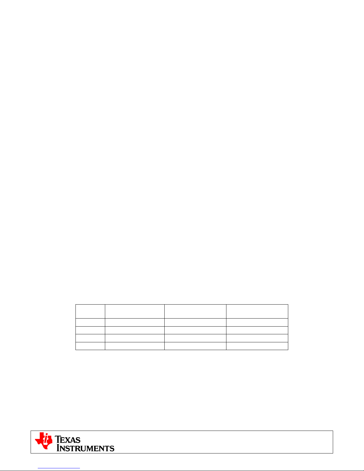
Hardware Overview
Below is a list of all the major functional blocks present on the board and a short description of its function, Fig
2, shows the location of these blocks on the motor control board and a few key connector locations.
ISO controlCARD socket: controlCARD slot; controlCARD has built-in isolated XDS100 emulator.
+12V Control Power Entry: Connectors to optionally provide an external 12V supply for logic and gate drive
power. The 12V supply can also be regulated on board from the DC bus depending on the setting of JP1.
DC Bus Power Entry: Connect the +24V AC/DC supply provided with the kit.
DRV8412: DRV8412 Dual Full Bridge PWM Motor Driver as well as external passive components.
Current Sense: Low-side shunt current sensing on each half-bridge.
Reset Switch: Individual reset for each H-bridge, forced manually or through a GPIO from the MCU.
Mode Jumpers: Enable/disable c-by-c current limit, latched over-current and parallel or dual full-bridge mode.
Quadrature Encoder: Connections for an optional shaft encoder to interface to the MCU’s QEP peripheral.
Fig2: DRV8412-EVM Board Macros
2
v2.0
Page 3
C2000™ Systems Applications Collateral
Quick Start GUI
The kit comes with a GUI which provides a convenient way to evaluate the functionality of the kit and the
F28035 device without needing to learn and configure the underlying project software or install CCStudio. The
interactive interface using knobs, sliders, buttons, textboxes and graphs enables easy demo of microstepping of
bi-polar stepper motors as well as voltage and current control of brushed DC motors.
Hardware Setup
Note: Do not apply power to board before you have verified these settings!
The kit ships with the control card inserted and the jumper and switch settings pre-selected for connecting with
the GUI. However the user must ensure that these settings are valid on the board.
1) Make sure nothing is connected to the board, and no power is being supplied to the board.
2) Insert the Control card into the J1 controlCARD connector if not already populated.
4) Make sure the following jumpers & connector settings are valid on the DRV8412 base board i.e.
a. JP1 is in the VR1 position
b. JP3 is in the ROCADJ position
c. M1 is in the H position, M2 is in the L position and M3 is in the L position for dual axis Brushed
DC or Stepper motor. In order to run a single Brushed DC motor in parallel H-bridge mode the
user must change the mode jumpers from their default setting. For this mode M1 is in the L
position, M2 is in the H position and M3 is in the L position.
d. Switches S1 and S2 are in the middle position
5) Make sure that the following switches are set as described below on the F28035 controlCARD to enable
boot from flash and connection to the SCI
a. SW3: OFF (UP) position
b. SW2: Position 1 = ON (UP), Position 2 = ON (UP)
6) Connect a USB cable from J1 on the controlCARD to the host computer. LD4 on the controlCARD will
light up indicating that the USB is powered. Windows will then search for a driver for the device. If the
computer has CCSv4 or prior versions of it installed which supported XDS100 emulator, Windows
should be able to find the driver successfully. If not you will be prompted to install the driver. Installing
driver for USB to serial: Do not let Microsoft search for the driver, instead browse to the following
location on the USB stick drive shipped with the kit <Drive Name:\XDS100 Drivers v1.0>, windows
should now be able to find the driver and will install it. If Windows still does not find the driver, you may
have to repeat the process and point to the location pointed out previously. You may have to reboot the
computer for the drivers to come into effect. Once installed you can check if the installation was
completed properly by browsing to ControlPanel-> System->Hardware->Device Manager and looking
for USB Serial Port under Ports(COM&LPT). Note this port number down.
7) Connect the motor(s) you want to spin to the OUTA, OUTB, OUTC and OUTD terminals on the board.
The table below shows the connections for the motors included with the kit.
Terminal Dual Brushed DC Stepper
OUTA Motor 1 + Black,Orange/White
OUTB Motor 1 - Orange, Black/White
OUTC Motor 2 + Red, Yellow/White
OUTD Motor 2 - Yellow, Red/White
8) Connect the included DC power supply to the PVDD and GND banana jacks.
9) Once the power is connected the board will power up and you will see that the LED1, LED2 and LED3
on the DRV8412EVM base board are green (indicating power), LD1 on the controlCARD is green (also
indicating power) and LD3 (Red) on the controlCARD is blinking slowly indicating that code is runnin g.
Single Brushed DC
Parallel Mode
Motor +
Motor +
Motor Motor -
Software Setup
The QSG GUI (DRV8412GUIvX.exe) can be located on the drive that is shipped with the kit or once
controlSUITE is installed at the following location:
controlSUITE\developement_kits\DRV8412-EVM\~GUI\DRV8412GUIvX.exe
3
v2.0
Page 4

C2000™ Systems Applications Collateral
The GUI requires Microsoft .NET framework 3.5 SP1 or higher to run. Please ensure that this software is
installed prior to running this program.
The kit ships with a F28035 controlCARD which is pre-flashed with the code that enables interface to this GUI.
The flashed code is optimized for running current controlled microstepping of the stepper motor and voltage or
current control of the brushed DC motors that are available with the kit. Note that the performance of the motor
with the flashed image is not a metric of quality of control and performance levels achievable using the TI DMC
library. Please refer to the individual system software and corresponding literature for details. These can be
downloaded through controlSUITE. The flash image can be re-flashed using CCS if need be. The image can be
found in the drive shipped with the kit or at the following location:
controlSUITE\developement_kits\DRV8412-EVM\~GUI\DRV8412GUIvX.out
Running the GUI
1) Make sure all the jumper and connector settings are as described in the Hardware setup section.
2) Browse to and double click on DRV8412GUIvX.exe The GUI window should pop up (Fig 4).
3) The GUI should auto-detect and connect to your DRV8412-EVM. If auto-connect fails you will need to
set up the connection manually. The Connection Wizard is accessed through the Connection menu.
Click on “Connect to engine” to view a list of available targets. Now setup the Connection Wizard Dialog
to match figure 5. Select Piccolo 28035 from the Target list and Serial for connection method. You will
need to determine the correct COM port number for your system. This can be found by going to Control
Panel->System->Hardware tab->Device Manager->Ports(COM & LPT). And look for the one which is
described as USB Serial Port or similar. Hit Connect once done.
4
v2.0
Page 5

C2000™ Systems Applications Collateral
Fig4: GUI Startup
Fig5: GUI Setup Connections
4) If an incorrect image is flashed on the controlCARD the connection will fail. In this case it is
recommended to reflash the controlCARD with the correct image.
5) After the connection is established to the controller the type of motor can be selected by choosing the
corresponding tab in the GUI. If the selection needs to be changed the board should be power
cycled in order to safely connect a different motor.
6) At the bottom of the screen are three sets of controls common to either motor type:
• Enable Motor and Brake on Disable Check boxes: The Enable Motor check box is used to start
or stop the motor(s) from running. The Brake on Disable check box selects the action when the
motor is stopped. If unchecked all H-bridge switches are opened on disable and the motor is free
spinning. If checked the low-side switches are held closed effectively shorting the motor
connections and causing an abrupt stop.
• Fault Status: The on-screen LED will turn red whenever there is a fault signaled by the DRV8412.
To reset this fault ensure Enable Motor check box is unchecked and push the Reset Fault button.
• DC Bus Voltage: The measured DC bus voltage is displayed both digitally and graphically. The on-
screen LED can take three states depending on whether the DC bus is in or out of range. The
range can be adjusted individually for each motor type on the settings tabs.
o Yellow: DC bus is below the minimum value
o Green: DC bus is within limits
o Red: DC bus is above the maximum value
5
v2.0
Page 6

C2000™ Systems Applications Collateral
Fig 6: Common Controls
Dual Brushed DC Motor Control
1) User can choose a voltage or current control mode. Mode is chosen by selecting either the Voltage
Mode or Current mode tab. There is a knob to set the value and a gauge showing the setpoint. The
setpoint has a slew rate limit so there will be a delay between the knob setting and the gauge display.
The graph windows to the right show the current feedback for each motor.
2) There are two settings tabs to modify the DC Bus range and provide current loop tuning for each motor.
The parameters have been tuned for light loads and a 24V DC bus with a +/-20% tolerance.
Fig 7: All Brushed DC Mode Tabs
Stepper Motor Control
1) User can choose either a constant speed mode or an indexing mode.
2) The drop down box is used to set the number of microsteps per step (whole stepping to 128
microsteps/step).
3) The top graph displays the motor speed in steps/sec. The bottom graph displays the motor winding
currents. This is a high-speed datalogger graph which reads up an array or logged data from the target.
The currents on this graph are scaled in per-unit (pu) with a value of 1 pu representing 7.2 amps of
current. In order to run this graph for one cycle click on the green arrow. In order to continuously
refresh this graph click on the cycling arrows button. The graph’s default configuration is to trigger on a
rising edge of the A phase current at a level of 0.25pu.
4) In speed mode the user can adjust the desired motor speed and current using knobs. The change of
speed is subject to a slew rate limit. Actual speed is displayed on the radial gauge and on the graph.
5) In index mode the user can set the index distance, speed, acceleration, deceleration, idle and running
currents. The idle current sets the holding torque of the motor when it is not moving, the running current
sets the motor torque during an index. The index parameters have the following units and range.
a. Distance – units are microsteps and the range is the entire span of a signed 32-bit integer
b. Speed – 1-5000(step/sec)
c. Accel – 200-20000(steps/sec/sec)
6
v2.0
Page 7

C2000™ Systems Applications Collateral
d. Decel – 200-20000(steps/sec/sec)
6) There is one more tab which allows modification of the current loop tuning and allows the DC bus range
to be set. The parameters in the preflashed image have been tuned for light loads and a 24V DC bus
with a +/-20% tolerance.
Fig 8: Stepper Speed Mode with Graphs
Fig 9: Stepper Index Mode and Settings Tabs
7
v2.0
Page 8

C2000™ Systems Applications Collateral
Single Brushed DC Motor Control with Paralel H-bridge Mode
Note: The DRV8412 Mode jumpers must be modified from their default setting for this mode. With
power removed set M1 to L, M2 to H and M3 to L.
1) User can choose a voltage or current control mode. Mode is chosen by selecting either the Voltage
Mode or Current mode tab. There is a knob to set the value and a gauge showing the setpoint. The
setpoint has a slew rate limit so there will be a delay between the knob setting and the gauge display.
The graph window to the right shows the current feedback for the motor.
2) There is a settings tab to modify the DC Bus range and provide current loop tuning. The parameters
have been tuned for light loads and a 24V DC bus with a +/-20% tolerance.
Fig 10: All Brushed DC Parallel Mode Tabs
Shutting Down
1) Once finished evaluating, uncheck the Enable Motor check box to stop the motor. Once the motor
comes to a full stop the GUI can be closed. Now unplug the 24V DC power supply. As the capacitors
are charged the PVDD LED may remain ON for a couple of seconds. Do not touch the board unless this
LED goes OFF.
2) All future updates/enhancements to the GUI and/or Flash image would be made available through
controlSUITE.
3) Please note that the Flash image is meant for quick demonstration purpose only. For a more detailed
explanation and understanding on the control algorithm being used and tradeoffs, refer to the individual
project for the motor type and control method being implemented under
controlSUITE\developement_kits\DRV8412-EVM.
References
Information about the board settings and connections can be found on the Board Layout tab within the GUI.
This diagram shows the position of each connector, switch, jumper and test point.
8
v2.0
Page 9

C2000™ Systems Applications Collateral
The GUI and corresponding C2000 code were developed by D3 Engineering. The GUI was created using
Crosshairs Interface Designer from Crosshairs Embedded. There are links to each of the companies’ web sites
within the GUI. There is also information for downloading Crosshairs Interface Designer so that you can modify
the GUI that comes with this kit. The More… tab gives a brief overview of the Interface Designer software.
www.crosshairsembedded.com
www.d3engineering.com
For more information please refer to the following:
• Download and Install ControlSUITE
www.ti.com/controlSUITE
After controlSUITE install
• DRV8412-EVM HW Reference Guide: provides detailed information on the DRV8412-EVM hardware.
controlSUITE\development_kits\DRV8412-EVM\~Docs
• DRV8412-EVM-HWdevPkg: files related to the hardware (schematics, BOM, Gerber files, PCB, etc).
controlSUITE\development_kits \DRV8412-EVM\~DRV8412-EVM_HWdevPkg\
• DRV8412-EVM How to Run Guide: HW and CCStudio setup required for using p roje cts
controlSUITE\development_kits \DRV8412-EVM\~Docs
• All the projects for different motors can be found at
controlSUITE\development_kits \DRV8412-EVM\2xDC_Motor or \Stepper
• C2000 source code for the GUI project can be found at
controlSUITE\development_kits \DRV8412-EVM\GUI_project
• Crosshairs Embedded GUI .exe and project files can be found at
controlSUITE\development_kits \DRV8412-EVM\~GUI
9
v2.0
 Loading...