

Page 1
BLUES
PISTONE OLEODINAMICO PER CANCELLI AD ANTE BATTENTI
I
MANUALE ISTRUZIONI E CATALOGO RICAMBI
PISTONS OLEODYNAMIQUES POUR LA MOTORISATION DE PORTAILS A BATTANTS
F
NOTICE D'INSTRUCTION ET CATALOGUE PIECES DE RECHANGE
PISTONES OLEODINÁMICOS PARA CANCELAS A DOS PUERTAS
E
MANUAL ISTRUCCIONES Y CATALOGO REPUESTOS
HYDRAULIC PISTONS FOR HINGED GATES
GB
INSTRUCTION HANDBOOK AND SPARE PARTS CATALOGUE
ISTBLUES
V. 04.2008
ÖLDYNAMISCHE KOLBEN FÜR FLÜGELTORE
D
BEDIENUNGANWEISUNGEN UND ERSATZTEILLISTE
HYDRAULISCHE ZUIGERS VOOR VLEUGELPOORTEN
NL
GEBRUIKERSHANDLEIDING EN RESERVEONDERDELEN CATALOGUS
Telcoma srl - Via L. Manzoni, 11 - Z.I. Campidui - 31015 Conegliano - (TV) Italy
Tel. +39 0438-451099 - Fax +39 0438-451102 - Part. IVA 00809520265
http://www.telcoma.it E-mail: info@telcoma .it
Page 2

I F E
MODELLI E CARATTERISTICHE MODELES ET CARACTERISTIQUES MODELOS Y CARACTERISTICAS
I pistoni oleodinamici della serie BLUES sono composti da un motore elettrico monofase, da una pompa e da un pistone idraulico doppio effetto. Il tutto racchiuso in un
elegante carter in alluminio estruso che
funge anche da serbatoio olio.
La forza di spinta può essere regolata tramite una coppia di valvole by-pass.
In caso di anomalia o mancanza di alimentazione è consentita la manovra manuale.
Modelli
- BLUES 20/R
Reversibile–Corto–Senzarallentamento.
-BLUES21/RL
Reversibile – Lungo – Con rallentamento
idraulico.
-BLUES50/I
Irreversibile–Corto–Senzarallentamento.
-BLUES51/IL
Irreversibile – Lungo – Con rallentamento
idraulico.
Les pistons oléodynamiques mod. BLUES
sont composés d’un moteur électrique
monophasé, d’une pompe et d’un piston
hydraulique à double effet. Le tout renfermé
dans un carter en aluminium extrudé servant également de réservoir d’huile.
Deux valves by-pass règlent la force de
poussée.
En cas d’anomalie ou de coupure de courant la manoeuvre peut être effectuée
manuellement.
Modèles
-BLUES20/R
Réversible–Court–Sansralentissement.
-BLUES21/RL
Réversible – Long – Avec ralentissement
hydraulique.
-BLUES50/I
Irréversible–Court–Sansralentissement.
-BLUES51/IL
Irréversible – Long – Avec ralentissement
hydraulique.
Los pistones oleodinámicos de la serie
BLUES están compuestos por un motor
eléctrico monofásico, por una bomba y por
un pistón hidráulico de doble efecto.
Todo ello dentro de un elegante estuche de
aluminio fusionado que sirve también de
depósito para el aceite.
La fuerza de empuje puede ser regulada
mediante un par de válvulas by-pass.
En caso de anomalía o falta de alimentación
se puede operar de forma manual.
Modelos
-BLUES20/R
Reversible–Corto–Sindeceleración.
-BLUES21/RL
Reversible – Largo – Con deceleración
hidráulica.
-BLUES50/I
Irreversible–Corto–Sindeceleración.
-BLUES51/IL
Irreversible – Largo – Con deceleración
hidráulica.
Dati tecnici Données techniques Datos tecnicos u.m. BLUES 20 BLUES 21 BLUES 50 BLUES 51
Tensione di alimentazione
Forza di spinta regolabile
Corrente max assorbita
Potenza max assorbita
Condensatore
Portata pompa
Pressione max eserc. pompa
Corsa stelo
Velocità stelo
Angolo max di rotazione
Temperatura di funzionamento
Intervento termoprotezione
Grado di protezione
Classe di isolamento
Olio motore TS30
Intermittenza lavoro
Peso
Tension d’alimentation
Force de poussée réglable
Courant max absorbé
Puissance max absorbée
Condensateur
Débit pompe
Pression max fonct. pompe
Course tige
Vitesse tige
Angle max de rotation
Température de fonct.
Interv. thermoprotec.
Degré de protection
Classe d’isolation
Huile moteur TS30
Intermittence de fonctionnement
Poids
Tensión de alimentación
Fuerza de empuje regulable
Corriente máx. absorbida
Potencia máx. absorbida
Condensador
Capacidad de la bomba
Presión máx. ejerc. bomba
Movimiento perno
Velocidad perno
Angulo máx, de rotación
Temperatura de funcionamiento
Dispositivo termoprotección
Grado de protección
Clase de aislamiento
Aceite motor TS30
Intermitencia trabajo
Peso
Vac 230 230 230 230
0÷3000N 0÷3000 0÷3000 0÷3000
A 1,2 1,2 1,2 1,2
VA 280 280 280 280
µF8888
l/min 1 1 1 1
bar 40 40 40 40
mm 270 378 270 378
mm/s 12 12 12 12
° 105 105 105 105
°C -20+70 -8+70 -20+70 -8+70
°C +150 +150 +150 +150
IP 56 56 56 56
BBBB
l
% 707070 70
Kg 12,5 13,5 12,5 13,5
1,5
2 1,5 2
Guida all’installazione Guide à l’installation Guia para la instalacion u.m. BLUES 20 BLUES 21 BLUES 50 BLUES 51
Lunghezza max anta
Peso max anta
Movimento
Uso
Longueur max battant
Poids max battant
Mouvement
Usage
Longitud máx. puerta
Peso máx. puerta
Movimiento
Uso
m 2,5 4,5 2,5 4,5
Kg 350 500 350 500
* * ** **
(1) (1) (1) (1)
* Reversibile (necessita di elettroserratura)
** Irreversibile
(1) Residenziale / comunità
2
* Réversible (serrure électrique nécessaire)
** Irréversible
(1) Résidentiel/communauté
* Reversible (necesita autocierre)
** Irreversible
(1) Residencial/Comunidades
Page 3

GB D NL
MODELS AND SPECIFICATIONS MODELLE UND EIGENSCHAFTEN MODELLEN EN SPECIFICATIES
The BLUES hydraulic pistons consist of a
single-phase electric motor, a pump and a
hydraulic double-acting piston. These components are enclosed in an elegant aluminium casing which also acts as an oil tank.
The thrust force can be adjusted by means
of a pair of by-pass valves.
The gate can be released manually in the
case of power failure or malfunctioning
Models
- BLUES 20/R
Reversible – Short – Without deceleration.
- BLUES 21/RL
Reversible – Long – With hydraulic
deceleration.
- BLUES 50/I
Irreversible – Short – Without deceleration.
- BLUES 51/RL
Irreversible – Long – With hydraulic
deceleration.
Die öldynamischen Kolben der Serie BLUES
bestehen aus einem Einphasen-Elektromotor,
einer Pumpe und einem hydraulischen, doppelwirkenden Kolben. Diese Bestandteile
befinden sich alle in einem eleganten
Gehäuse aus Aluminium, das auch als Öltank
dient.
Die Triebkraft kann mit Hilfe eines Paars von
By-pass Ventilen geregelt werden. Im Falle
einer Betriebsstörung oder eines
Stromausfall ist der manuelle Betrieb möglich.
Modelle
-BLUES20/R
Nicht selbsthemmend – Kurz – Ohne SoftStopp
-BLUES21/RL
Nicht selbsthemmend – Lang – Mit
hydraulischemSoft-Stopp
-BLUES50/I
Selbsthemmend–Kurz–OhneSoft-Stopp
-BLUES51/IL
Selbsthemmend – Lang – Mit hydraulischem
Soft-Stopp
De hydraulische zuigers van de serie BLUES
bestaan uit een éénfase-elektromotor, een
pomp en een hydraulische zuiger met een
dubbele werking. Het geheel is in een fraaie
aluminium behuizing ondergebracht, die
ook als oliereservoir dient.
De krachtregeling kan aangepast worden
d.m.v. een paar by-pass ventielen. In het
geval van stroomstoringen of installatieproblemen kan de poort met de hand bediend
worden.
Modellen
-BLUES20/R
Omkeerbaar–Kort–Zondervertraging.
-BLUES21/RL
Omkeerbaar – Lang – Met hydraulische
vertraging.
-BLUES50/I
Onomkeerbaar–Kort–Zondervertraging.
-BLUES51/IL
Onomkeerbaar – Lang – Met hydraulische
vertraging
Technical data Technische Daten Technische gegevens u.m. BLUES 20 BLUES 21 BLUES 50 BLUES 51
Power supply
Adjustable thrust
Max. current consumption
Max. input
Capacitor
Pump capacity
Pump max. working pressure
Rod stroke
Rod speed
Max. angle of rotation
Operating temperature
Thermal cut-out device
Degree of protection
Insulation rating
Motor oil TS30
Working intermittence
Weight
Installation guide
Max. gate length
Max. gate weight
Movement
Use
Versorgungsspannung
Regulierbare Triebkraft
Max. Stromaufnahme
Max. Leistungsaufnahme
Kondensator
Pumpenleistung
Max. Betriebsdruck Pumpe
Kolbenstangenhub
Kolbenstangengeschwindigkeit
Max. Öffnungswinkel
Betriebstemperatur
Ansprechen Überhitzungsschutz
Schutzgrad
Isolationsklasse
Motoröl TS30
Arbeitsintermittenz
Gewicht
Leitfanden für die Installationen
Max. Länge Torflügel
Höchstgewicht Torflügel
Bewegung
Anwendung
Voedingsspanning
Verstelbare krachtinstelling
Maximaal stroomverbruik
Maximaal vermogensgebruik
Condensator
Pompopbrengst
Maximale werkdruk pomp
Slaglengte zuigerstang
Snelheid zuigerstang
Maximale draaihoek
Temperatuurbereik
Inschakeling thermische beveiliging
Beschermingsgraad
Isolatieklasse
Motorolie TS30
Intermitterend bedrjif
Gewicht
Vac 230 230 230 230
0÷3000N 0÷3000 0÷3000 0÷3000
A 1,2 1,2 1,2 1,2
VA 280 280 280 280
µF
l/min 1 1 1 1
bar 40 40 40 40
mm 270 378 270 378
mm/s 12 12 12 12
° 105 105 105 105
°C -20+70 -8+70 -20+70 -8+70
°C +150 +150 +150 +150
IP 56 56 56 56
l
% 707070 70
Kg 12,5 13,5 12,5 13,5
888 8
BBBB
1,5
2 1,5 2
Richtlijn voor de installatie u.m. BLUES 20 BLUES 21 BLUES 50 BLUES 51
Max. vleugellengte
Max gewicht van de vleugel
Beweging
Gebruik
m 2,5 4,5 2,5 4,5
Kg 350 500 350 500
* * ** **
(1) (1) (1) (1)
* Reversible (electric lock required)
** Irreversible
(1) Residential/communal
* Nicht selbsthemmende Bewegung (Elektroschweißung notwendig)
** Selbsthemmend
(1) Anwendung Wohnhaus/Appartmentgebäude
* Omkeerbaar (elektrische vergrendeling nodig)
** Onomkeerbaar
(1) Woonhuizen/Woonblokken
3
Page 4
4
Page 5
I F E
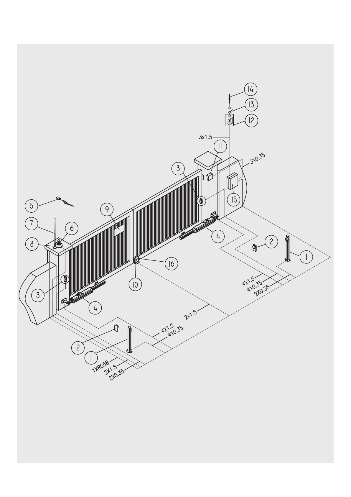
QUADRO D’INSIEME TABLEAU D’ENSEMBLE CUADRO DE CONJUNTO
1. Coppia di fotocellule a colonnina in
uscita
2. Battute di arresto ante in apertura
3. Coppia di fotocellule in entrata
4. Pistone
5. Radiocomando
6. Lampeggiatore
7. Antenna
8. Supporto per lampeggiatore + antenna
9. Cartello di avvertenza
10. Battuta di arresto ante in chiusura
11. Selettore
12. Interruttore differenziale
13. Interruttore generale
14. Linea di alimentazione
15. Centralina elettronica di comando
16. Elettroserratura
1. Couple de photocellules en sortie sur la
colonne
2. Butées d’arrêt battants en ouverture
3. Couple de photocellules en entrée
4. Piston
5. Télécommande radio
6. Clignotant
7. Antenne
8. Support de clignotant + antenne
9. Panneau d’avertissement
10. Butée d’arrêt battants en fermeture
11. Sélecteur
12. Interrupteur différentiel
13. Interrupteur général
14. Ligne d’alimentation
15. Centrale électronique de commande
16. Serrure électrique
1. Par de fotocélulas a columna en salida
2. Topes de cierre de las puertas
3. Par de fotocélulas de entrada
4. Pistón
5. Radiomando
6. Intermitente
7. Antena
8. Soporte para intermitente + antena
9. Cartel de advertencia
10. Tope de la puerta en cierre
11. Selector
12. Interruptor diferencial
13. Interruptor general
14. Línea de alimentación
15. Centralita electrónica de mando
16. Electrocierre
GB D NL
GENERAL VIEW GESAMTANSICHT TOTAALBEELD
1. Pair of photo cells for posts at exit
2. Opening gate limit stops
3. Pair of photo cells at entry
4. Piston
5. Remote control
6. Blinker
7. Antenna
8. Support for blinker + antenna
9. Warning sign
10. Closing gate limit stop
11. Selector
12. Differential switch
13. On/off switch
14. Power supply line
15. Electronic control unit
16. Electric lock
1. Paar Photozellen auf Ausgangspfosten
2. Endanschlag Torflügel bei der Öffnung
3. Paar Photozelle am Eingang
4. Kolben
5. Fernbedienung
6. Blinklicht
7. Antenne
8. Träger für Blinklicht + Antenne
9. Hinweisschild
10. Endanschlag Torflügel bei der
Schließung
11. Wahlschalter
12. Differentialschalter
13. Hauptschalter
14. Versorgungslinie
15. Elektronisches Steuergehäuse
16. Elektroschloß
1. Een set fotocellen (2) voor op zuil (uitgang)
2. Aanslag bij het openen van de poort
3. Een set fotocellen (2) (ingang)
4. Zuiger
5. Radiografische afstandsbediening
6. Knipperlicht
7. Antenne
8. Steun voor knipperlicht en antenne
9. Waarschuwingsbordje
10. Aanslag bij het sluiten van de poort
11. Sleutelschakelaar
12. Aardlekschakelaar
13. Hoofdschakelaar
14. Voedingskabel
15. Elektronische besturingskast
16. Elektrische vergrendeling
5
Page 6
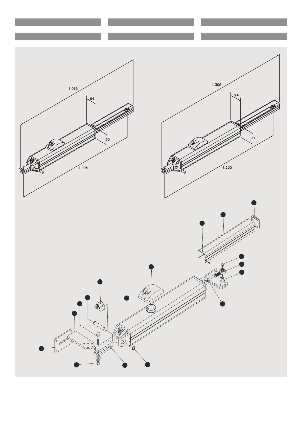
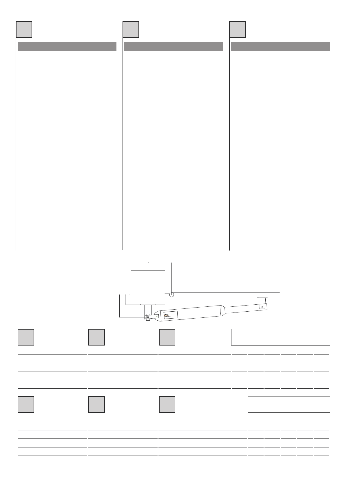
MISURE D’INGOMBRO MEASURES D’ENCOMBREMENT MEDIDAS MAXIMAS EXTERNAS
OVERALL MEASUREMENTS AUSSENABMESSUNGEN MAATSCHETS
Fig. 1A / Abb. 1A Fig. 1B / Abb. 1B
8
17
5
4
3
7
11
10
9
12
13
15
16
2
1
6
14
Fig. 2 / Abb. 2
6
Page 7
I F E
COMPONENTI PRINCIPALI COMPOSANTS PRINCIPAUX COMPONENTES PRINCIPALES
1. Dado autobloccante
2. Piastra di attacco a colonna
3. Staffa di attacco posteriore con fori per
l’aggiustaggio finale
4. Vite di fissaggio posteriore
5. Perno di fissaggio posteriore
6. Supporto a forcella
7. Pistone
8. Tappo con chiave
9. Vite fissaggio copristelo
10. Copristelo
11. Tappo chiudi stelo
12. Anello seeger D.13 inox
13. Testina snodata
14. Anello seeger D.12 inox
15. Staffa anteriore
16. Dado M12
17. Connettore di alimentazione motore
1. Ecrou de sûreté
2. Plaque de fixation sur la colonne
3. Bride de fixation arrière dotée de trous
pour le réglage final
4. Vis de fixation arrière
5. Goujon de fixation arrière
6. Fourche de support
7. Piston
8. Bouchon muni de clé
9. Vis de fixation cache-tige
10. Cache-tige
11. Embout d’arrêt de la tige
12 Anneau seeger D.13 inox
13. Tête articulée
14. Anneau seeger D.12 inox
15. Etrier avant
16 Ecrou M12
17. Conneteur d’alimentation moteur
1. Dado autoblocante
2. Chapa de sujección a la columna
3. Abrazadera de ajuste posterior con orificios para el ajuste final
4. Tornillos de fijación posterior
5. Perno de fijación posterior
6. Soporte a horquilla
7. Pistón
8. Tapón con llave
9. Tornillos de fijación del perno
10. Cubre perno
11. Tapón cierra perno
12. Anillo seeger D.13 inox
13. Cabeza articulada
14. Anillo seeger D.12 inox
15. Grapa anterior
16. Tuerca M12
17. Conector de alimentacion motor
GB D NL
MAIN COMPONENTS HAUPTBESTANDTEILE VOORNAAMSTE ONDERDELEN
1. Self-locking nut
2. Fixing plate to post
3. Rear fixing plate with holes for final
adjustment
4. Rear clamping screw
5. Rear fixing pin
6. Fork support
7. Piston
8. Cap with key
9. Rod cover clamping screw
10. Rod cover
11. Rod cover cap
12. Seeger ring D.13 inox
13. Jointed head
14. Seeger ring D.12 inox
15. Front bracket
16. Nut M12
17. Motor power supply connector
1. Selbstblockierende Mutter
2. Befestigungsplatte auf Pfosten
3. Hinterer Befestigungsbügel mit
Bohrungen zur Endeinstellung
4. Hintere Befestigungsschraube
5. Hinterer Befestigungsbolzen
6. Gabelkopf
7. Kolben
8. Deckel mit Schlüssel
9. Befestigungsschraube für die Kolbenstangenabdeckung
10. Kolbenstangenabdeckung
11. Deckel für Kolbenstangenverschluß
12. Seeger-Ring D.13 inox
13. Gelenkkopf
14. Seeger-Ring D.12 inox
15. Vorderer Bügel
16. Mutter M12
17 Motoranschlussklemme
1. Zelfborgende moer
2. Bevestigingsplaat aan kolom
3. Bevestigingsbeugel voor achterzijde
met gaten voor definitieve afstelling
4. Bevestigingsbout voor achterzijde
5. Bevestigingspen voor achterzijde
6. Vorksteun
7. Zuiger
8. Dop met sleutel
9. Bevestigingsschroef voor zuigerstang
afdekking
10. Zuigerstang afdekking
11. Einddop voor zuigerstang afdekking
12. Seegerring D.13 inox
13. Scharnierkop
14. Seegerring D.12 inox
15. Beugel voorzijde
16. Moer M12
17. Verbinding motorvoeding
7
Page 8

I F E
INSTALLAZIONE PISTONE INSTALLATION DU PISTON INSTALACION PISTON
Il pistone deve essere installato in corrispondenza di un rinforzo longitudinale della struttura dell’anta.
Attacco posteriore
Per determinare il corretto posizionamento
dell’attacco posteriore al pilastro vedere
Fig. 3 e attenersi alle misure indicate in
Tab. 1 (BLUES 20/50) e Tab. 2 (BLUES
21/51).
L’attacco posteriore, sul pilastro, va fatto
tramite la piastra3elastaffa2diFig.2.
Se il pilastro è in metallo l’attacco posteriore può essere fatto mediante saldatura (Fig.
4) o viti (Fig. 5).
Se, invece, il pilastro è in cemento, o altro
materiale che offra buon aggancio, l’attacco può essere fatto tramite tasselli ad
espansione.
Se, infine, il pilastro è in materiale friabile
si consiglia di murare 4 viti di lunghezza
adeguata su cui fissare la piastra.
Attacco anteriore
L’attacco anteriore va fatto fissando l’apposita staffa (part. 15 di Fig. 2) all’anta del
cancello (Fig. 6).
Eventuali compensazioni possono essere
ottenute regolando la testina snodata (part.
13 di Fig. 2).
Le piston doit être installé au niveau du renforcement longitudinal se trouvant sur la
structure du battant.
Fixation arrière
Pour déterminer la position correcte de la
fixation arrière sur le pilier, voir Fig. 3 et
suivre les instructions concernant les
dimensions indiquées dans le tableau 1
(BLUES 20/50) et dans le tableau 2 (BLUES
21/51).
La fixation arrière sur le pilier doit être effectuée à l’aide de la plaque 3 et de la bride 2
(voir Fig. 2).
Si le pilier est en métal, la fixation arrière
peut être effectuée à l’aide d’une soudure
(Fig. 4) ou au moyen de vis (Fig. 5).
Si au contraire le pilier est en ciment, ou
dans un autre matériau permettant un bon
accrochage, la fixation peut être effectuée à
l’aide de vis tamponnées.
Enfin si le pilier est en matériau friable, il est
conseillé d’y sceller 4 vis ayant une longueur adéquate sur lesquelles la plaque
pourra être fixée.
Fixation avant
La jonction avant s'obtient en fixant l'étrier
(détail 15 de la Fig. 2), prévu à cet effet, au
battant du portail (fig. 6).
D'éventuelles compensations peuvent être
obtenues en réglant la tête articulée (détail
13 de la Fig. 2).
El pistón se debe instalar en la parte donde
está el refuerzo longitudinal de la estructura de la puerta.
Fijación Posterior
Para determinar el correcto posicionamiento de la fijación posterior a la columna, ver
Fig. 3 y respetar las medidas indicadas en la
tabla 1 (BLUES 20/50) y Tabla 2 (BLUES
21/51).
La fijación posterior, en la columna se realiza con la chapa 3 y la agarradera 2 de la
Fig.2.
Si la columna es de metal, la fijación posterior se puede realizar soldandola (Fig. 4) o
con tornillos (Fig. 5).
Si por el contrario, la columna es de cemento o en otro material que permita una buena
fijación, la misma se puede realizar con
tacos a expansión.
Finalmente, si la columna es en material
friable se aconseja introducir en la pared 4
tornillos de altura adecuada en los cuales
fijar la chapa.
Fijación anterior
La unión delantera debe hacerse fijando la
abrazadera expresamente prevista (pieza 15
de la fig. 2) a la hoja de la cancela (fig. 6).
Eventuales compensaciones se pueden
obtener regulando la cabeza articulada
(pieza 13 de la fig. 2).
b
c
Fig. 3 / Abb. 3
a
IFE
Misura “a”
Misura “b”
Misura “c” max
Corsa stelo
Angolo max apertura
Mesure “a”
Mesure “b”
Mesure “c” max
Course tige
Angle max d’ouverture
Medida “a”
Medida “b”
Medida “c” máx.
Movimiento perno
Angulo máx. apertura
IFE
Misura “a”
Misura “b”
Misura “c” max
Corsa stelo
Angolo max apertura
Mesure “a”
Mesure “b”
Mesure “c” max
Course tige
Angle max d’ouverture
Medida “a”
Medida “b”
Medida “c” máx.
Movimiento perno
Angulo máx. apertura
Tab.1 - BLUES 20/50
mm 100 110 120 130 140
mm 90 100 110 120 110
mm 50 60 70 80 90
mm 190 210 230 250 250
° 110 115 115 100 90
Tab.2 - BLUES 21/51
mm 200 230 270 220
mm 170 140 100 150
mm 140 160 200 160
mm 370 370 370 370
°90909090
8
Page 9
GB D NL
PISTON INSTALLATION INSTALATION DES KOLBENS INSTALLATIE VAN DE ZUIGER
The piston should be installed in line with a
longitudinal reinforcement of the gate
frame.
Rear connection
For positioning the rear connection to the
post correctly, see Fig. 3 and scrupulously
observe the measurements given in Table 1
(BLUES 20/50) and Table 2 (BLUES 50/51).
Use plates 3 and 2 , shown in Fig. 2., for the
rear connection to the post.
If the post is metal, the rear plate can be soldered (Fig. 4) or screwed on (Fig. 5).
If the pillar is made of concrete or other
material with a suitable solid surface, the
plate may be fixed using screw anchors.
If the pillar is made of a brittle material, it is
advisable to insert 4 screws of a suitable
length to secure the plate.
Front connection
The front connection is accomplished by fixing the relative bracket (part 15 Fig. 2) to the
gate (Fig. 6).
Any compensation may be obtained by
adjusting the jointed head (part 13 Fig. 2.).
Der Kolben muß in Übereinstimmung mit
einer Längsverstrebung der Torstruktur
montiert werden.
Hintere Befestigung
Um die korrekte Positionierung der hintere
Befestigung am Pfosten bestimmen zu können, siehe Abb. 3 und sind die in der Tabelle
1 (BLUES 20/50) und Tabelle 2 (BLUES
21/51) angegebenen Maße zu beachten.
Die hintere Befestigung auf dem Pfosten
erfolgt mit Hilfe der Platte 3 und des Bügels
2 der Abb. 2.
Wenn der Pfosten aus Metall besteht, kann
die hintere Befestigung durchAnschweißen
(Abb. 4) oder mit Schrauben (Abb. 5) erfolgen.
Wenn der Pfosten hingegen aus Beton oder
einem anderen Material besteht, das einen
guten Halt bietet, kann die Befestigung mit
Spreizdübeln erfolgen.
Wenn der Pfosten jedoch aus porösem
Material besteht, ist es ratsam, 4 Schrauben
entsprechender Länge einzumauern, auf
denen die Platte zu befestigen ist.
Vordere Befestigung
Der vordere Anschluß erfolgt durch
Befestigung des entsprechenden Bügels
(Detail 15 in Abb. 2) auf dem Torflügel (Abb.
6).
Eventuelle Ausgleichungen können durch
Regulierung des Gelenkkopfes (Detail 13 in
Abb. 2) erzielt werden.
De zuiger moet op een horizontale ligger
van de vleugelconstructie van de poort geïnstalleerd worden.
Bevestiging aan de achterzijde
Zie fig. 3 om de juiste plaats voor de bevestiging aan de kolom te bepalen. Volg de
afmetingen in tabel 1 (BLUES 20/50) en
tabel 2 (BLUES 21/51).
De bevestiging aan de kolom wordt
gemaakt m.b.v. de platen 3 en 2 zoals blijkt
uit fig. 2.
Als de kolom is gemaakt van metaal, kan de
bevestiging gelast (fig. 4) of vastgeschroefd
(fig. 5) worden.
Wanneer de kolom echter van beton of een
ander stevig materiaal is, dan kunt u volstaan met bevestiging d.m.v. keilbouten.
Als de kolom van brokkelig materiaal is
gemaakt, is het verstandig om 4 schroeven
die lang genoeg moeten zijn in het materiaal te storten of te metselen en daar de
bevestigingsplaat aan te bevestigen.
Bevestiging aan de voorzijde
De bevestiging aan de voorzijde moet tot
stand gebracht worden door de speciale
beugel (det. 15 op fig. 2) aan de poortvleugel
vast te maken (fig. 6).
Dit kan eventueel gecompenseerd worden
door de scharnierkop (det. 13 op fig. 2) af te
stellen.
b
c
Fig. 3 / Abb. 3
a
GB D NL
Measurement “a”
Measurement “b”
Measurement “c” max.
Rod stroke
Max. opening angle
Maß “a”
Maß “b”
Maß “c” max.
Kolbenstangenhub
Max. Öffnungswinkel
Maat “a”
Maat “b”
Maat “c” max.
Slaglengte zuigerstang
Max. openingshoek
GB D NL
Measurement “a”
Measurement “b”
Measurement “c” max.
Rod stroke
Max. opening angle
Maß “a”
Maß “b”
Maß “c” max.
Kolbenstangenhub
Max. Öffnungswinkel
Maat “a”
Maat “b”
Maat “c” max.
Slaglengte zuigerstang
Max. openingshoek
Tab.1 - BLUES 20/50
mm 100 110 120 130 140
mm 90 100 110 120 110
mm 50 60 70 80 90
mm 190 210 230 250 250
° 110 115 115 100 90
Tab.2 - BLUES 21/51
mm 200 230 270 220
mm 170 140 100 150
mm 140 160 200 160
mm 370 370 370 370
°90909090
9
Page 10
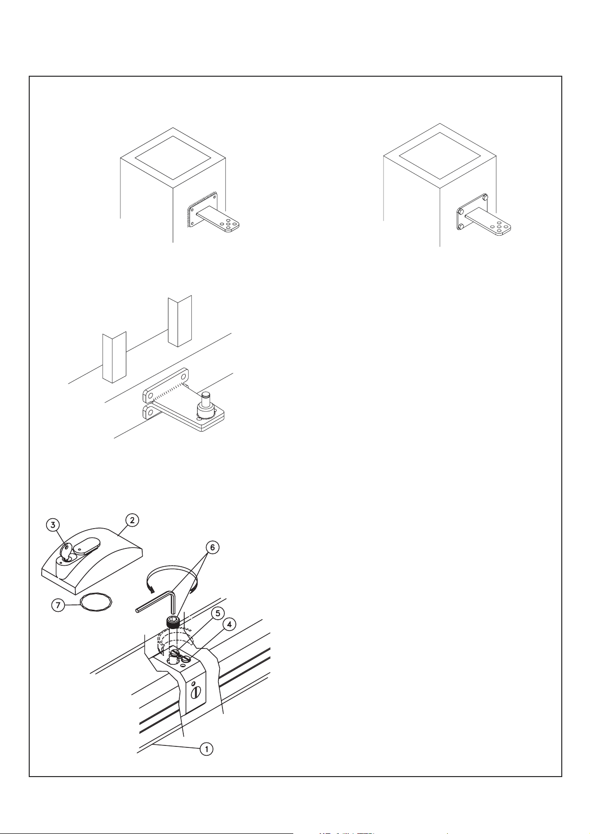
Fig. 4 / Abb. 4 Fig. 5 / Abb. 5
Fig. 6 / Abb. 6
1. Pistone
2. Tappo
3. Chiave
4. Valvola di regolazione in
apertura
5. Valvola di regolazione in
chiusura
6. Manopola di sblocco
7. Anello OR
1. Piston
2. Bouchon
3. Clé
4. Soupape de régulation en
ouverture
5. Soupape de régulation en
ferme
6. Manette de déblocage
7. Bague OR
1. Piston
2. Cap
3. Key
4. Regulating valve for opening
5. Regulating valve for closing
6. Release handle
7. O-ring
1. Kolben
2. Deckel
3. Schlüssel
4. Ventil der Öffnungseinstellung
5. Ventil der Schließeinstellung
6. Drehknopf für die
Entriegelung
7. O-Ring
Fig. 7 / Abb. 7
10
1. Pistón
2. Tapón
3. Llave
4. Válvula de regulación en
abertura
5. Válvula de regulación en
cierre
6. Manivela de desbloqueo
7. Anillo OR
1. Zuiger
2. Dop
3. Sleutel
4. Krachtregelventiel (tijdens
opengaan)
5. Krachtregelventiel (tijdens
sluiten)
6. Ontgrendelknop
7. O-ring
Page 11

I F E
CORSA DEL PISTONE COURSE DU PISTON MOVIMIENTO DEL PISTÓN
Il pistone ha una sua corsa prestabilita che
può essere utilizzata totalmente o, qualora
si voglia ridurre il tempo di apertura, solo
parzialmente.
Per una apertura di 90 gradi è valida la regola:
corsa stelo = “a” + “b” Fig. 3.
Pertanto, riducendo i valori di “a” e “b” ri-
portati in Tab. 1 (BLUES 20/50) e Tab. 2
(BLUES 21/51), si avrà una corsa più corta
e, quindi, i tempi di apertura e chiusura risulteranno più brevi.
Più cresce la lunghezza dell’anta e maggiore deve essere il tempo di apertura aumentando proporzionalmente i valori “a” e “b”
di Tabb. 1 e 2.
BLUES 20/21: BLUES 20/21:
Per un corretto funzionamento del pistone
ad anta tutta chiusa o tutta aperta, la corsa
dello stelo non deve svilupparsi per intero.
RALLENTAMENTO IDRAULICO
Il rallentamento idraulico dei
avviene solo se si utilizzal’interacorsadello
stelo(378mm).
BLUES 21/51
Le piston a une course déjà fixée qui peut
être utilisée totalement ou bien partiellement si l’on désire diminuer le temps d’ouverture.
Pour une ouverture de 90 degrés, appliquer
la formule suivante:
course tige = “a” + “b” Fig. 3.
Par conséquent, si l’on diminue les données
“a” et “b” du tableau 1 (BLUES 20/50) et du
tableau 2 (BLUES 21/51), la course sera plus
courte et les temps d’ouverture et de fermeture seront plus brefs.
Plus la longueur du battant augmente et
plus l’on doit faire durer le temps d’ouverture en augmentant proportionnellement les
données “a” et “b” des tableaux 1 et 2.
Pour que le piston fonctionne correctement
quand le battant est complètement fermé
ou complètement ouvert, la tige ne doit pas
aller jusqu’au bout de sa course.
RALENTISSEMENT HYDRAULIQUEDES
Le ralentissement hydraulique des BLUES
21/51 ne se produit que si l’on utilise la
course entière de la tige (378mm).
El pistón tiene su movimiento preestablecido, que puede utilizarse totalmente o si se
quiere reducir el tiempo de apertura, sólo
parcialmente.
Para una abertura de 90 grados es válida la
siguiente regla:
movimiento perno = “a”+”b” .Fig. 3
Por lo tanto, reduciendo los valores de “a” y
de “b” que están en la tabla 1 (BLUES 20/50)
y Tab. 2 (BLUES 21/51), se obtendrá un
movimiento más corto y así se abreviarán
los tiempos de apertura y de cierre.
Cuanto más ancha es la medida de la puerta, mayor es el tiempo de apertura, aumentando proporcionalmente los valores “a” y
“b” de Tab. 1 y de Tab. 2.
BLUES 20/21:
Para un correcto funcionamiento del pistón
con la puerta totalmente cerrada o totalmente abierta, el movimiento del perno no
debe completar su ciclo.
DESACELERACIÓN HIDRÁULICA
La desaceleración hidráulica de BLUES
21/51 se produce sólo si se usa toda la
carrera del vástago (378 mm).
GB D NL
PISTON STROKE KOLBENHUB SLAGLENGTE VAN DE ZUIGER
The piston has a pre-set stroke which can
be used wholly, or only partially to reduce
the opening time.
For a 90° opening the following rule is valid:
rod stroke = “a” + “b” .Fig. 3
Consequently, by reducing the values of “a”
and “b” indicated in Table 1 (BLUES
20/50)and Table 2 (BLUES 21/51) the stroke
will be shorter and therefore the opening
and closing times will be reduced.
The longer the length of the gate, the longer
the opening time must be. In this case
increase the values of “a” and “b” in Tables
1 and 2 in proportion.
BLUES 20/21: BLUES 20/21:
For correct piston operation when the gate
is completely closed or open, the rod should
not fully complete its stroke.
HYDRAULICSLOWING
Hydraulic slowingdown of theBLUES 21/25
only occurs if the whole rod stroke is
accomplished(378mm).
Der Kolben hat einen festgelegten Hub, der
vollständig oder, wenn man die Öffnungszeit verringern möchte, nur teilweise
genutzt werden kann.
Für einen Öffnungswinkel von 90° gilt folgende Regel:
Kolbenhub = “a” + “b” .Abb. 3
Daher bewirkt eine Verringerung der Werte
“a” und “b”, die in der Tabelle 1 (BLUES
20/50) und Tabelle 2 (BLUES 21/51) aufgeführt sind, einen kürzeren Hub und somit
kürzere Öffnungs- und Schließzeiten.
Je größer die Länge des Torflügels je länger
muß auch die Öffnungszeit sein, indem die
Werte “a” und “b” der Tabellen 1 und 2 proportionell erhöht werden.
Um einen einwandfreien Betrieb bei vollständig geschlossenem bzw. geöffnetem
Tor zu gewährleisten, ist es notwendig, daß
der Kolbenhub nicht vollständig genutzt
wird.
HYDRAULISCHE VERLANGSAMUNGDER
Die hydraulische Verlangsamung der
BLUES 21/51 erfolgt nur, wenn der
gesamte Hub des Schaftes ausgenutzt
wird (378 mm).
De zuiger heeft een vaste slaglengte, die
geheel benut kan worden, of gedeeltelijk,
om de openingstijd te verkorten. Voor een
90° openingshoek geldt de volgende regel:
slaglengte van de zuigerstang = “a” + “b” .Abb. 3
Door verkleining van de waarde “a” en “b”
uit tabel 1 (BLUES 20/50) en tabel 2 (BLUES
21/51), wordt de slag korter, waardoor de
openings- en sluitingstijd ook korter wordt.
Hoe groter de poortvleugel, hoe groter de
openingstijd moet zijn door de waarden “a”
en “b” uit tabel 1 en 2 evenredig te verhogen.
BLUES 20/21:
Om ervoor te zorgen dat de zuiger goed
functioneert is het van belang dat u de zuiger zowel bij het openen als bij het sluiten
niet zijn volledige slag laat maken.
HYDRAULISCHE VERTRAGINGVAN
De hydraulische vertraging van de BLUES
21/51 vindt alleen plaats als de hele slag
van de stang (378 mm) gebruikt wordt.
11
Page 12

I F E
CONNETTORE DI
ALIMENTAZIONE MOTORE
Per alimentare il motore portare un cavo a 4
poli, sez. 4 x 1,5 mmq, dalla centralina elettronica di comando al connettore di alimentazione motore (Fig. 8).
Per ottenere l’inversione del senso di marcia del pistone, invertire i fili di fase sulla
morsettiera della centralina elettronica.
1. Fase
2. Comune
3
12
3. Fase
4. Messa a terra
Fig. 8
REGOLAZIONE
FORZA TRASMESSA
Laregolazione dellaforza dispinta èaffidata allevalvole
diregolazione (Part.4e5Fig.7).Consigliamol'usodiun
misuratore di forza. Con lavalvola color oro si regolala
forzain chiusura,con lavalvola colorargento siregola la
forza in apertura.I BLUES sono settatida Telcoma con
una forza di spinta pari a circa metà della loro potenza
massima. Sesi vuole aumentarela forza bisognaagire
sullevalvole avvitandole.
N.B. Non avvitare le valvole fino alla fine della loro
corsa. Questo impedisce il flusso dell'olio e si
avrebbe quindi una perdita di potenza.
Consigliamo, inoltre, di mettere del grasso tra
forcellae staffaposteriore (Part.2-3 esploso).
N.B. Una volta installato il pistone, togliere l'anello
ORdal tappo(Part. 7di Fig.7)
CONNECTEUR D’ALIMENTATION
MOTEUR
Pour alimenter le moteur, porter un câble à
4 pôles, de 4 X 1,5 mm2 de section, de la
centrale électronique de commande au
connecteur d’alimentation moteur (Fig. 8).
Pour inverser le sens de fonctionnement du
piston, inverser les fils de phase sur la
plaque à bornes de la centrale électronique.
1. Phase
2. Comun
3. Phase
4. Mise à terre
REGULATION DE LA FORCE
TRANSMISE
Le réglage de la force de poussée est assuré par les
soupapes de réglage (Pos. 4 et 5 Fig. 7). Nous
conseillons d'utiliserun mesureurde force.La soupape
couleur or règle la force en fermeture tandis que la
soupapecouleur argentrègle laforce enouverture.
Les BLUESsont réglés parTelcoma avec uneforce de
poussée égale à environ la moitié de leur puissance
maximum.Si l'onsouhaite augmenterla forceil fautagir
surles soupapesen lesvissant.
N.B. Ne pas visser les soupapes jusqu'à la fin de
leur course. Cela empêche le passage de l'huile et
entraînerait par conséquent une perte de
puissance. Nous conseillons également demettre
de lagraisse entre la fourcheet l'étrier arrière(Pos.
2-3vue éclatée).
N.B. Une fois le piston installé, enlever le joint
toriquedu bouchon(Pos. 7- Fig.7)
CONECTOR DE
ALIMENTACIÓN MOTOR
Para alimentar el motor, llevar un cable a 4
pulgadas, sección 4x 1,5 mm. cuadrados, de
la centralita electrónica de mando al conector de alimentación motor (Fig. 8).
Para obtener la inversión del sentido de la
marcha del pistón, invertir los cables de
fase en la abrazadera de la centralita
electrónica.
1. Fase
2. Comune
3. Fase
4. Descarga a tierra
REGULACIÓN DE LA FUERZA
TRANSMITIDA
La fuerza de empuje se regula con las válvulas de
regulación (Det. 4 y 5 Fig.7). Aconsejamos utilizar un
medidor de fuerza. Conla válvula dorada seregula la
fuerza de cierre, con la válvula plateada se regula la
fuerza de apertura. Los BLUES son ajustados por
Telcoma con una fuerza de empuje equivalente a la
mitadde supotencia máxima.Sise quiereaumentarla
fuerzahay queenroscar lasválvulas.
Nota. No enrosque las válvulas hasta su fin de
carrera. Porque impediría el flujo de aceite y se
produciríauna pérdidade potencia.
También recomendamos poner grasa entre la
horquillay elestribo trasero(Det. 2-3despiece).
NOTADespués de instalar elpistón, quite la junta
tóricaOR deltapón (Det.7 de Fig.7)
ELETTROSERRATURA SERRURE ELECTRIQUE ELECTROCIERRE
I BLUES 50/51 sono pistoni irreversibili e
quindi non richiedono elettroserratura.
I BLUES 20/21, invece, sono pistoni reversibili e, quindi, richiedono l’installazione dell’elettroserratura.
Con ante di lunghezza inferiore a cm 180 è
possibile evitare il costo dell’elettroserratura usando il BLUES 50 che garantisce la tenuta in chiusura e in apertura.
Con ante di lunghezza superiore a cm 180,
invece, per garantire la tenuta in chiusura e
salvaguardare l’impianto, qualunque sia il
modello utilizzato, è necessario installare
l’elettroserratura.
Nelle Figg. 9 et 10 sono raffigurati due
esempi di installazione fra i più comuni. Si
raccomanda di rispettare tassativamente le
quote riportate in dette Figg., in quanto, le
dilatazioni termiche potrebbero provocare
delle variazioni dimensionali tali da causare
difficoltà nell’innesto e/o disinnesto dello
scrocco.
In caso di montaggio laterale dell’elettroserratura, si consiglia di installare anche
una guida che, come indicato in Fig. 9, consenta un perfetto posizionamento dell’anta
in chiusura.
Les pistons BLUES 50/51 sont irréversibles
et donc n’ont pas besoin de serrure électrique.
Les pistons BLUES 20/21 au contraire sont
réversibles et donc ont besoin de la serrure
électrique.
Avec des battants d’une longueur inférieure
à 180 cm il est possible d’économiser le
coût d’une serrure électrique en utilisant le
modèle BLUES 50 qui garantit la tenue du
portail aussi bien en fermeture qu’en ouverture.
Avec des battants d’une longueur supérieure à 180 cm, en revanche, pour garantir la
tenue en fermeture et protéger l’installation,
il est nécessaire, quelque soit le modèle utilisé, d’installer une serrure électrique.
Voir les figures 9 et 10 où se trouvent deux
exemples de pose les plus courants.
Respecter impérativement les cotes indiquées sur ces figures car les dilatations
thermiques pourraient provoquer des variations de dimensions et rendre difficile l’enclenchement et/ou le déclenchement du
déclic.
Si la serrure électrique est montée latéralement, il est conseillé d’installer un guidage,
comme indiqué à la fig.9, qui facilite le posi-
BLUES 50/51 son pistones irreversibles por
lo tanto no necesitan electrocierre.
BLUES 20/21, por el contrario son pistones
reversibles por lo tanto necesitan la instalación de un electrocierre.
Con puertas de longitud inferior a 180 cm.
es posible evitar el coste del electrocierre
utilizando los BLUES 50 que garantizan el
tope en apertura y en cierre.
Con puertas de longitud superior a 180 cm.
, para garantizar el funcionamiento de los
topes en cierre y proteger la instalación,
independientemente del modelo utilizado
es necesario instalar el electrocierre.
En las Figuras 9 y 10 están representados
dos ejemplos de instalación, entre los más
comunes.
Se recomienda respetar táxativamente las
cuotas representadas en dichas figuras porque las dilataciones térmicas pueden provocar variaciones de dimensión tales de causar dificultades en la juntura o disjuntura.
En el caso de montaje lateral del electrocierre, se aconseja instalar también una guía
que, como indican la Fig. 9, permita un perfecto posicionamiento de la puerta en cierre.
tionnement du battant lors de la fermeture.
12
Page 13

GB D NL
MOTOR POWER
MOTORANSCHLUSSKLEMME VERBINDING MOTORVOEDING
SUPPLY CONNECTOR
To feed the motor, connect a 4-pole cable
witha4x1.5sq.mmsectionbetween the
electronic control unit and the motor power
supply connector (Fig. 8).
To reverse the piston direction of movement, invert the phase wires on the terminal
board of the control unit.
Zur Stromversorgung des Motors ein 4-poliges Kabel mit einem Durchschnitt von 4x1,5
mm2 von der elektronischen Steuerung zur
Klemme der Motorstromversorgung führen
(Abb. 8).
Um eine Umkehr der Kolbenlaufrichtung zu
erzielen, sind die Phasendrähte auf der
Klemmenleiste der Steuerung umzukehren.
1. Phase
2. Common
3
12
3. Phase
4. Heart
Fig. 8 / Abb. 8
THRUST ADJUSTMENT EINSTELLUNG DER
KRAFTÜBERTRAGUNG
The thrust force is adjusted by the special control
valve (detail 4 and 5Fig. 7). Werecommend useof a
forcemeasurement tool.
Thegolden valveadjusts theforce onclosure,and the
silvervalve controlsforce onopening.
The BLUES are set by Telcoma with a thrust forceof
approximately half their maximum power. If the force
needsto beincreased, thevalvecan betightened.
N.B.Do nottighten thevalves fullydown. Thiswill
preventthe oilflow andcausea lossinpower.
We also recommend the application of grease
between the fork and rear bracket (detail 2-3
explodeddrawing).
N.B. Once the piston is installed, remove the Oringfrom thecap (detail 7 ofFig.7)
Die Einstellung der Schubkraft erfolgt über die
Regelventile (Det. 4 und 5 auf Abb. 7). Es wird der
Einsatz eines Kraftmessers empfohlen. Mit dem
goldfarbenen Ventil wird die Kraft beim Schließen
eingestellt, mitdem silberfarbenen Ventil die Kraftbeim
Öffnen. BLUES ist von Telcoma mit einer Schubkraft
voreingestellt, die ungefähr der Hälfte der
Höchstleistung entspricht.Soll die Krafterhöht werden,
müssendie Ventile zugedrehtwerden.
N.B. Die Ventile nicht bis zumAnschlag zudrehen.
Dadurch wird der Öldurchfluss behindert, was zu
einem Leistungsverlust führt. Es wird weiterhin
empfohlen, zwischen Gabel und hinterem Bügel
Schmierfett aufzubringen (Det. 2-3
Explosionsgraphik).
N.B. Nach Installation des Antriebs den O-Ring
vomDeckel entfernen(Det. 7auf Abb.7).
1. Phase
2. Allgemein
3. Phase
4. Erdung
Om de motor te voeden dient er een 4 polige kabel met een doorsnede van 4 x 1,5
mm2 tussen de elektronische besturingskast en de verbinding motorvoeding (fig. 8)
aangesloten te worden.
Om de zuiger in de andere richting te laten
draaien, moeten de fasedraden op de klemmenstrook van de elektronische besturingskast verwisseld worden.
1. Fase
2. Nul
3. Fase
4. Aarde
KRACHTREGELING
Afstellingvan deduwkracht vindtviaregelkleppen (deel
4 en5 afb.7) plaats.Wij radenu aan eeninrichting voor
het meten van de kracht te gebruiken. Met de
goudkleurige klep wordt de kracht bij het sluiten
afgesteld, metde zilverkleurige klep wordtde kracht bij
het openen afgesteld. De BLUES zijn door Telcoma
afgesteld op eenduwkracht van ongeveer dehelft van
het maximumvermogen daarvan. Als u de kracht wilt
verhogendient ude kleppenaan tedraaien.
N.B. Draai dekleppen niet helemaaldicht. Dit belet
doorstroming vande olie ener zou duseen verlies
aan vermogen ontstaan. Wij raden u bovendien
aanvet tussende vorken deachterbeugel (deel2-3
explosietekening)aan tebrengen.
N.B. Nadat de zuiger is geïnstalleerd dient u de Oringvan dedop tehalen (deel7 vanafb.7)
ELECTRIC LOCK ELEKTROSCHLOSS ELEKTRISCHE VERGRENDELING
BLUES 50/51 are irreversible pistons and
the electric lock is therefore not required.
BLUES 20/21 are reversible pistons and an
electric lock is required.
For gates less than 180 cm in length, the
installation of the BLUES 50/51 will ensure
complete restraint of the gate (closed or
open), thus eliminating the need for an electric lock.
For gates exceeding 180 cm in length, however, an electric lock must be installed to
ensure that the gate cannot be forced open
and that the system is protected.
Two of the most common types of installation are illustrated in Figs. 9 and 10.
Scrupulously observe the measurements
given in these figures, as expansion due to
heat may produce variations which could
cause difficulty in the engagement and/or
disengagement of the spring latch.
If the electric-lock is fitted to the side, the
installation of a proper guide is recommended to ensure the right position of the
gate when closing (see Fig. 9).
Bei den BLUES 50/51 handelt es sich um
selbsthemmende Kolben und erfordern
daher kein Elektroschloß.
Bei den BLUES 20/21 hingegen handelt es
sich um nicht selbsthemmende Kolben und
erfordern daher die Installation eines
Elektroschlosses
Bei einer Länge des Torflügels von weniger
als 180 cm ist es möglich, die Kosten des
Elektroschlosses durch Verwendung des
BLUES 50 zu vermeiden, der sowohl bei der
Schließung als auch bei der Öffnung einen
sicheren Halt gewährleistet.
In den Abb. 9 und 10 sind zwei der häufigsten Montagebeispiele abgebildet. Es wird
empfohlen, die in den Abbildungen angegebenen Werte strikt zu beachten, da wärmebedingte Ausdehnungen zu Maßveränderungen führen können, die Probleme bei der
Verriegelung und/oder Entriegelung verursachen können.
Im Falle einer seitlichen Montage des
Elektroschloßes ist es ratsam, auch eine
Führung zu installieren, die wie in Abb. 9
angegeben eine perfekte Positionierung des
Flügels bei der Schließung ermöglicht.
De BLUES 50/51 zijn geblokkeerde (onomkeerbare) zuigers en een elektrische vergrendeling is dan ook niet noodzakelijk.De
BLUES 20/21 zijn daarentegen zonder blokkering (omkeerbaar) en daarom is een elektrische vergrendeling wel noodzakelijk.
Voor poortvleugels die minder dan 180 cm
lang zijn is de noodzaak voor een elektrische
vergrendeling niet meer aanwezig is omdat
als er een BLUES 50gemonteerd wordt deze
voor volledige inklemming van de poort
zorgt.
Voor poortvleugels die langer zijn dan 180
cm moet echter wel een elektrische vergrendeling geplaatst worden om te voorkomen dat de poort, ongeacht het model,
opengebroken kan worden.
Op fig. 9 en 10 worden de twee meest gangbare types weergegeven. De afmetingen die
hier aangegeven worden dienen nauwkeurig opgevolgd te worden om dat door uitzetting i.v.m. verhitting veranderingen in de
maten kunnen ontstaan, die moeilijkheden
kunnen veroorzaken bij het koppelen of ontkoppelen van de veer. Als de elektrische vergrendeling aan de zijkant gemonteerd moet
worden is het noodzakelijk om voor een
goede geleiding te zorgen om ervoor te zorgen dat de poort tijdens het sluiten in de
juiste stand staat (zie fig. 9).
13
Page 14

I F E
Montaggio laterale per un’anta
Montage latéral pour un battant
128
150
100
Fig. 9 / Abb. 9
5
48
4
36
OLIO MOTORE HUILE MOTEUR ACEITE MOTOR
Montaje lateral para una puerta
Side fitting for single gates
Seitliche Montage bei einflügeligen Toren
Installatie aan de zijkant voor 1 vleugelpoorten.
Livello dell'olio.
L'olio deve essere visibile facendo rientrare
completamente lo stelo e inclinando
leggermente la parte anteriore del BLUES
(circa15cmdalla partedello stelo).
Ogni 6/7.000 manovre e, comunque, ogni
3/4 anni, bisogna provvedere alla completa
sostituzione dell’olio (su entrambi i pistoni
in presenza di cancelli a due ante).
1. Rabbocco dell’olio.
a. Togliere il tappo (part. 8 di Fig. 2).
b. Aggiungere olio sino a quando si intravede
(vedi anche "livello dell' olio").
c. Rimettere il tappo e chiudere a chiave.
2. Sostituzione dell’olio.
a. Togliere il perno di fissaggio posteriore
(part. 5 di Fig. 2).
b. Capovolgere il pistone, avendo l’accor-
tezza di raccogliere l’olio esausto in un
recipiente idoneo.
c. Ruotare il pistone e riportarlo in posizio-
ne di lavoro.
d. Aggiungere olio(circa 2 litri).
e. Rimettere il tappo e chiudere a chiave.
Niveaudel'huile.
L'huile doit être visible en faisant rentrer
complètement latige et eninclinant légèrement
la partie avant du BLUES (environ 15 cm du
côtédelatige).
Effectuer une vidange complète de l’huile
(sur les deux pistons quand le portail a deux
battants) toutes les 6000/7000 manoeuvres
et de toute façon tous les 3/4 ans.
1. Comment rajouter de l’huile
a. Enlever le bouchon (dét. 8 - Fig. 2)
b. Ajouter de l'huile jusqu'à ce qu'elle
apparaisse (voir aussi «niveau de l'huile»).
c. Remettre le bouchon et fermer à clé.
2. Vidange de l’huile
a. Enlever le goujon de fixation arrière (dét.
5 - Fig. 2)
b. Renverser le piston en ayant soin de
recueillir l’huile usagée dans un récipient.
c. Retourner le piston et le replacer dans
sa position de fonctionnement.
d. Ajouter de l’huile (environ 2 litres).
e. Remettre le bouchon et fermer à clé.
Niveldeaceite.
El aceite se debe poder ver haciendo entrar
completamente el vástago e inclinando,
ligeramente, la parte delantera del BLUES
(unos15cmdesde laparte delvástago).
Después de 6/7000 maniobras y siempre
cada 3/4 años, hace falta sustituir por completo el aceite ( en los dos pistónes cuando
se trata de cancelas con dos puertas).
1. Introdución del aceite.
a. Quitar el tapón (part. 8 de Fig. 2).
b. Añada aceite hasta que se vea (véase
también "Nivel de aceite").
c. Cerrar el tapón y la llave.
2. Sustitución del aceite.
a. Quitar el perno de fijación posterior
(part. 5 de Fig. 2).
b. Volcar el pistón, teniendo la precaución
de recoger el aceite en un recipiente
adecuado.
c. Girar el pistón y volverlo a poner en su
posición original.
d. Añadir aceite(aprox. 2 litros).
e. Cerrar con el tapón y con la llave.
N.B.
Subito dopo la sostituzione dell’olio potreb-
be verificarsi qualche anomalia di funzionamento dovuta all’aria entrata nel circuito.
Dopo una decina di manovre la situazione
si normalizza e il pistone torna a funzionare
regolarmente.
Si consiglia olio codice Telcoma: TS 30.
14
N.B.
Quelques anomalies de fonctionnement
peuvent se produire juste après avoir
vidangé l’huile en raison de l’air entré dans
le circuit. La situation devrait redevenir normale après une dizaine de manoeuvres et
permettre un fonctionnement régulier du
piston.
Il est conseillé d’utiliser de l’huile Telcoma
code: TS 30.
N.B.
Después de la sustitución del aceite, se
puede presentar alguna anomalía de funcionamiento debida al aire en el circuito.
Después de una decina de movimientos la
situación se normaliza y el pistón vuelve a
funcionar de manera regular.
Se aconseja utilizar aceite codigo
Telcoma: TS 30.
Page 15

GB D NL
48 36
4
Montaggio centrale per due ante
100
Montage centrale pour deux battants
Montaje central para dos puertas
Central fitting for double gates
Zentrale Montage bei zweiflügeligen Toren
150
128
Installatie in het midden voor 2 vleugelpoorten.
Fig. 10 / Abb. 10
5
MOTOR OIL MOTORÖL MOTOROLIE
Oil level.
The oil must be visible when the rod is
completely retractedand thefront section of the
BLUES is slightly inclined (approx. 15 cm from
thesideofthe rod).
Ölstand.
Das Öl muss sichtbar sein, wenn der Schaft
ganz eingefahren und das Vorderteil von
BLUES etwas schräg gehalten wird (ca. 15 cm
aufderSchaftseite).
Oliepeil.
De olie moet zichtbaar zijn wanneer u de
zuigerstang helemaal ingeschoven hebt en het
voorste deel van BLUES enigszins schuin
houdt (circa 15 cm vanaf het deel van de
zuigerstang).
Every 6/7,000 movements and, in any case,
every 3/4 years, the oil should be changed
(of both pistons in the case of double gates).
1. Topping up of oil.
a. Remove the cap (Part 8 Fig. 2).
b. Add oil until it can be seen from the
exterior (see all "oil level").
c. Replace cap and lock with key.
2. Oil change.
Alle 6/7.000 Bewegungen oder mindestens
nach 3/4 Jahren ist ein vollständiger
Ölwechsel durchzuführen (bei beiden
Kolben im Falle von zweiflügeligen Toren).
1. Ölnachfüllung
a. Deckel abnehmen (Detail 8 Abb. 2).
b. Öl nachfüllen, bis man es sieht (siehe auch
"Ölstand").
c. Deckel wieder aufsetzen und mit dem
Schlüssel arretieren.
Iedere 6000 à 7000 manoeuvres, of in ieder
gevalelke3à4jaar dient de olie volledig
ververst te worden (van beide zuigers in het
geval van een poort met 2 vleugels).
1. Olie bijvullen.
a. Haal de dop (detail 8, fig. 2) eraf.
b. Vul zoveel olie bij tot u de olie kunt zien (zie
ook"oliepeil").
c. Doe de dop er weer op en sluit deze met
de sleutel.
a. Remove the rear fixing pin (Part 5 Fig. 2).
b. Turn the piston upside down and collect
the oil in a suitable container.
c. Rotate the piston and bring it back to
operating position.
d. Add oil (approximately 2 litres).
e. Replace cap and lock with key.
N.B.
Immediately following the oil change some
operating problems may occur due to the
entry of air into the system. After about a
dozen movements the situation should
return to normal and the piston should operate correctly.
Recommended oil, Telcoma : TS30.
2. Ölwechsel
a. Den hinteren Befestigungsbolzen ent-
fernen (Detail 5 Abb. 2).
b. Den Kolben umkehren, wobei darauf zu
achten ist, daß das ausfließende Altöl in
einem geeigneten Behälter aufgefangen
wird.
c. Den Kolben drehen und wieder in die
Arbeitsposition zurückversetzen.
d. Öl einfüllen (ungefähr 2 Liter).
e. Deckel wieder aufsetzen und mit dem
Schlüssel arretieren.
ANMERKUNG
Unmittelbar nach dem Ölwechsel können
Funktionsstörungen auftreten, die auf das
Eindringen von Luft in den Ölkreislauf
zurückzuführen sind. Nach etwa zehn
Bewegungen müßte sich die Situation wieder normalisieren und der Kolben müßte
2. Olie verversen.
a. Verwijder de achterste bevestigingspen
(detail 5, fig. 2).
b. Draai de zuiger op zijn kop en vang de
olie op in een geschikte bak.
c. Draai de zuiger weer om en plaats hem
weer in de juiste werkstand.
d. Vul olie bij (ongeveer 2 liter).
e. Doe de dop er weer op en sluit deze met
de sleutel.
N.B.
Direct na het verversen van de olie kunnen
er storingen in de werking optreden als
gevolg van het binnendringen van lucht in
het circuit. Na een tiental manoeuvres moet
de situatie weer normaal zijn. De zuiger
moet dan weer goed functioneren.
Het is verstandig om Telcoma code: TS 30.
wieder normal funktionieren.
Es wird das Telcoma code: TS 30.
15
Page 16

I F E
MANOVRA MANUALE
In situazioni di emergenza (temporanea
mancanza di alimentazione di rete, anomalie di funzionamento, etc.) l’apertura o la
chiusura del cancello può avvenire manualmente .(BLUES 50/51)
Per aprire manualmente il cancello operare come segue.
1. Sbloccare l’elettroserratura, se installata, tramite l’apposita chiave in dotazione.
2. Togliere il tappo con chiave (part. 2 di
Fig. 7).
3. Ruotare in senso antiorario (per 2 giri,
circa) la manopola zigrinata di sblocco
(part. 6 di Fig. 7) servendosi della chiave
esagonale in dotazione.
4. Aprire manualmente il cancello.
Ad apertura avvenuta, volendo lasciare il
cancello aperto, si consiglia di bloccare di
nuovo la manopola zigrinata (ruotandola in
senso orario) e richiudere il tappo con chiave.
Volendo, invece, richiudere il cancello
ancora in situazione di emergenza e,
quindi, manualmente, operare come segue.
1. Ruotare in senso antiorario (per 2 giri,
circa) la manopola zigrinata di sblocco
(part. 6 di Fig. 7).
2. Chiudere manualmente il cancello.
3. Ruotare in senso orario la manopola zigrinata di sblocco (part. 6 di Fig. 7) e richiudere il tappo con chiave.
Una volta superata la situazione di emergenza, per richiudere o aprire il cancello basta dare i rispettivi comandi APRE/ CHIUDE.
FONCTIONNEMENT MANUEL FUNCIONAMIENTO MANUAL
En cas d’urgence (coupure momentanée du
courant, mauvais fonctionnement, etc.) on
peut effectuer l’ouverture et la fermeture du
portail manuellement .(BLUES 50/51)
Pour ouvrir manuellement le portail, procéder de la façon suivante.
1. Déverrouiller la serrure électrique, si
elle est installée, à l’aide de la clé spéciale en dotation.
2. Enlever l’embout muni de clé (dét. 2 Fig. 7).
3. Tourner (environ 2 tours), en utilisant la
clé hexagonale en dotation, la manette
moletée de déblocage (dét. 6 - Fig. 7)
dans le sens inverse des aiguilles d’une
montre.
4. Ouvrir le portail manuellement.
Une fois que l’ouverture s’est produite, si
l’on désire laisser le portail ouvert, il est
conseillé de bloquer à nouveau la manette
moletée (en la tournant dans le sens des
aiguilles d’une montre) et de refermer l’embout à clé.
Si l’on désire, au contraire, refermer le
portail en situation d’urgence, et donc
manuellement, procéder de la façon suivante.
1. Tourner (2 tours environ) la manette
moletée de déblocage (dét 6 - Fig. 7)
dans le sens inverse des aiguilles d’une
montre.
2. Fermer le portail manuellement.
3. Tourner la manette moletée de déblocage (dét 6 - Fig. 7) dans le sens des
aiguilles d’une montre et refermer l’embout à clé.
En situation normale, pour ouvrir ou fermer
le portail, il suffit d’utiliser les commandes
OUVRE/FERME.
En situaciones de emergencia (falta temporal de alimentación a la red, anomalías de
funcionamiento, etc.) la apertura o el cierre
de la cancela puede realizarse manualmente .(BLUES 50/51)
Para abrir manualmente la cancela realizar
las siguientes operaciones:
1. Desbloquear el electrocierre, con la relativa llave incluida, si es que está instalada.
2. Quitar el tapón con la llave (Part. 2 de
Fig. 7).
3. Girar en sentido contrario a las agujas
del reloj (más o menos dos veces) la
manivela estriada de desbloque (part. 6
de Fig. 7) usando la llave hexagonal
incluida.
4. Abrir manualmente la cancela
Cuando ya está abierta, si se quiere
dejar así, se aconseja bloquear otra vez
la manivela (girándola en el sentido de
las agujas del reloj y volver a cerrar el
tapón con la llave.
Si lo que se desea es volver a cerrar la
cancela en situación de emergencia
se debe hacer manualmente siguiendo estos pasos:
1. Girar en el sentido contrario a las agujas
del reloj (más o menos 2 veces) la manivela estriada de desbloqueo (part. 6 de
Fig. 7).
2. Cerrar manualmente la cancela.
3. Girar en el sentido de las agujas del
relojla manivela estriada de desbloqueo
(part. 6 de Fig. 7) y cerrar el tapón con la
llave.
Una vez que cesa la situación de emergencia, para volver a cerrar o abrir la cancela,
basta dar los respectivos mandos
ABRE/CIERRA.
ANOMALIE DI FUNZIONAMENTO.
RIMEDI.
1. Il cancello non apre. I motori funzionano, ma non avviene il movimento
di apertura.
a. Verificare che la manopola zigrinata di
sblocco (Part. 6 di Fig. 7) sia bloccata
(BLUES 50/51).
b. Verificare che non vi siano difetti di as-
setto meccanico del cancello (per
esempio, sfregamento tra le parti terminali delle ante o interferenza tra le ante
e la battuta al suolo).
c. In presenza di BLUES 20/21, reversibili,
controllare l’elettroserratura.
d. Se il pistone esegue la manovra inversa
(chiusura invece di apertura) invertire i
fili di fase sulla morsettiera della centralina elettronica.
e. Assicurarsi che lo stelo del pistone non
sia arrivato in battuta, verificando le misure riportate in Fig. 3 con relative Tabb.
1et2.
ANOMALIES DE FONCTIONNEMENT.
REMEDES
1. Le portail ne s’ouvre pas. Les moteurs
marchent mais la manoeuvre d’ouverture ne s’effectue pas.
a. Contrôler que la manette moletée (dét. 6
de la Fig. 7) soit bloquée (BLUES 50/51).
b. Contrôler qu’il n’y ait pas un mauvais
positionnement mécanique du portail
(par exemple, frottement entre les extrémités des battants ou contact entre les
battants et la butée se trouvant sur le
sol).
c. Si le BLUES 20/21, réversible, a été uti-
lisé, contrôler la serrure électrique.
d. Si le piston effectue une manoeuvre
inverse (fermeture au lieu d’ouverture)
inverser les fils de phase sur la plaque à
bornes de la centrale électronique.
e. S’assurer que la tige du piston ne soit
pas arrivée à la butée en contrôlant les
dimensions indiquées sur les tableaux 1
et 2 de la Fig. 3.
ANOMALIAS DE FUNCIONAMIENTO.
REMEDIOS.
1. La cancela no se abre. El motor funciona pero no se realiza el movimiento de abertura.
a. Verificar que la manivela estriada de
desbloque (Part. 6 de Fig. 7 este bloqueada .(BLUES 50/51)
b. Verificar que no haya defectos de órden
mecánico en la cancela ( por ejem. rozamiento entre las partes terminales de
las puertas, o interferencia entre las
puertas y los topes del suelo).
c. Cuando existan BLUES 20/21 reversi-
bles, controlar la eléctrocerradura.
d. Si el pistón realiza la maniobra inversa,
(cierre en lugar de abertura), invertir los
cables de fase en los bornes de la centralita electrónica.
e. Asegurarse que el perno del pistón no
haya llegado al tope, verificando las
medidas escritas en Fig. 3 con las relativas tablas 1 y 2.
16
Page 17

GB D NL
MANUAL OPERATION MANUELLER BETRIEB HANDMATIGE BEDIENING
In emergency situations (temporary power
failure, malfunctioning etc.) the gate can be
opened or closed manually .(BLUES 50/51)
To open the gate manually, proceed as follows:
1. Release the electric lock, if installed,
using the special key provided.
2. Remove the cap with key (Part 2 Fig. 7).
3. Turn the knurled release handle counterclockwise (for approx. two turns) (Part 6
Fig. 7), using the supplied Allen wrench.
4. Open the gate manually.
Lock the knurled release handle again (by
turning it clockwise) to leave the gate open
and replace the cap with key.
To close the gate manually in an emergency situation, proceed as follows:
1. Turn the knurled release handle (Part 6
Fig. 7) counter-clockwise for approximately two turns (Part 6 Fig. 7).
2. Close the gate manually.
3. Turn the knurled release handle (Part 6
Fig.9) clockwise and close the cap with
the key.
Once the emergency situation is over, to reopen or close the gate simply press the
respective OPEN/CLOSE buttons.
In Notsituationen (zeitweiliger Stromausfall
oder Betriebsstörungen usw.) kann die Öffnung oder Schließung des Tores manuell
ausgeführt werden .(BLUES 50/51)
Um das Tor manuell zu öffnen, ist wie folgt
zu verfahren:
1. Das Elektroschloß, sofern ein solches
montiert ist, mit dem entsprechenden
mitgelieferten Schlüssel deblockieren.
2. Den Deckel mit dem Schlüssel entfernen (Detail 2 Abb. 7).
3. Den gerändelten Drehknopf zur
Entriegelung (Detail 6, Abb. 7) unter
Verwendung des mitgeleiferten
Imbusschlüssels gegen den
Uhrzeigersinn drehen (ungefähr
2Umdrehungen).
4. Das Tor manuell öffnen.
Wenn das Tor nach erfolgter Öffnung offen
bleiben soll, ist es ratsam, den gerändelten
Drehknopf erneut zu blockieren (durch
Drehen im Uhrzeigersinn) und den Deckel
mit Schlüssel wieder zu schließen.
Soll das Tor hingegen noch in der
Notsituation wieder manuell geschlossen
werden, ist wie folgt vorzugehen.
1. Den gerändelten Drehknopf zur
Entriegelung (um ungefähr 2
Umdrehungen) gegen den
Uhrzeigersinn drehen (Detail 6 Abb. 7).
2. Das Tor manuell schließen.
3. Den gerändelten Drehknopf zur
Entriegelung (Detail 6 Abb. 7) im
Uhrzeigersinn drehen und den Deckel
mit dem Schlüssel wieder schließen.
Sobald die Notsituation beseitigt ist, genügt
es zum Schließen oder Öffnen des Tores die
entsprechenden Befehle Öffnen/ Schließen
zu erteilen.
In noodgevallen (tijdelijke stroomuitval en
storingen etc.) kan de poort handmatig geopend en gesloten worden .(BLUES 50/51)
De poort kan op de volgende manier
handmatig geopend worden;
1. Ontgrendel de elektrische vergrendeling, indien geïnstalleerd, m.b.v. de speciaal bijgeleverde sleutel.
2. Haal de dop met de sleutel eraf (detail 2,
fig. 7).
3. Draai de gekartelde ontgrendelknop
(detail 6, fig. 7) ongeveer twee slagen
tegen de wijzers van de klok in (detail 6,
fig. 9); maak daarbij gebruik van de zeskantsleutel die bij de levering inbegrepen is.
4. Open de poort handmatig.
Als de poort open staat en als u de poort
open wilt laten staan dan adviseren wij u de
ontgrendelknop weer te vergrendelen (door
hem met de wijzers van de klok mee te
draaien) en de dop met de sleutel er weer op
te doen.
Als u de poort in noodgevallen echter
weer dicht wilt doen moet u handmatig
het volgende doen:
1. Draai de ontgrendelknop (detail 6, fig. 7)
ongeveer twee slagen tegen de wijzers
van de klok in.
2. Sluit de poort handmatig.
3. Draai de ontgrendelknop (detail 6, fig. 7)
met de wijzers van de klok mee en sluit
de dop met de sleutel.
Zodra de noodsituatie over is, kunt u de
poort opnieuw openen of sluiten door de
OPENEN of SLUITEN knop in te drukken.
OPERATING PROBLEMS.
REMEDIES
1. The gate does not open. The motors
function, but there is no opening
movement.
a. Check that the knurled release handle
(Part 6 Fig. 7) is locked (BLUES 50/51).
b. Check that the gate has no mechanical
defects (e.g. that the ends of the gate do
not rub together or that there is no
obstruction between the gates and the
gate limit stop in the ground).
c. In the case of the reversible BLUES
20/21, control the electric lock.
d. If the piston carries out the opposite
movement (closure instead of opening)
invert the phase wires on the control
unit terminal board.
e. Ensure that the piston rod has not
arrived at the extreme end of its stroke,
checking the measurements indicated
in Fig. 3 with tables 1 and 2.
If the measurement is greater, move the
rod back slightly by adjusting the
FUNKTIONSSTÖRUNGEN.
ABHILFE
1. Das Tor öffnet sich nicht. Die Motoren
funktionieren, es erfolgt jedoch trotzdem keine Öffnungsbewegung.
a. Überprüfen, ob der gerändelte
Drehknopf zur Entriegelung (Detail 6
Abb. 7) blockiert ist (BLUES 50/51).
b. Überprüfen, ob beim Tor keine mechani-
schen Fehler vorliegen (z.B. ob die
äußersten Enden der Flügel aneinander
reiben oder ob zwischen den Flügeln
und dem Torstopper auf dem Boden
Interferenzen bestehen).
c. Bei selbsthemmenden BLUES 20/21 das
Elektroschloß kontrollieren.
d. Wenn der Kolben die falsche
Drehrichtung ausführt (Schließen statt
Öffnen), sind die Phasendrähte an der
Klemmenleiste der elektronischen
Steuerung umzuklemmen.
e. Sicherstellen, daß die Kolbenstange
nicht anschlägt, indem die in der Abb. 3
angegebenen Maße mit denjenigen der
STORINGEN EN OPLOSSINGEN
1. De poort gaat niet open. De motoren
werken, maar er is geen beweging.
a. Controleer of de ontgrendelknop (detail
6, fig. 7) vergrendeld is (BLUES 50/51).
b. Controleer of de poort geen mechani-
sche defecten vertoont (b.v. dat de einden van de poortvleugels niet botsen of
dat de vleugels de aanslag op de grond
niet raken).
c. Indien er een BLUES 20/21 gemonteerd
is, zonder blokkering, dient u de elektrische vergrendeling te controleren.
d. Als de zuiger zich in de tegengestelde
richting beweegt (sluiten in plaats van
openen) moet u de fasedraden verwisselen op de klemmenstrook van de besturingskast.
e. Zorg ervoor dat de zuigerstang niet in de
uiterste stand staat. Controleer de afmetingen in tabel 1 en 2 op fig. 3.
Als de afmeting groter is, plaats de zui-
17
Page 18

I F E
Se la misura fosse superiore fare rientrare
leggermente lostelo mediante laregolazione
della partefilettata del perno esagonale della
forcella(Part.13Fig.2).
f. Verificare la regolazione delle valvole
by-pass (Part. 4 et 5 di Fig. 7).
2. Il cancello non apre o non chiude. Il
motore elettrico non funziona e non si
avverte, quindi, alcun rumore o vibrazione.
a. Verificare che l’apparecchiatura elettro-
nica sia regolarmente alimentata.
b. Verificare l’efficienza dei fusibili.
c. Verificare l’efficienza dei condensatori
di avviamento motori.
d. Verificare, con l’ausilio di adeguati stru-
menti diagnostici, che le funzioni dell’apparecchiatura elettronica siano corrette.
e. Accertarsi che il motore riceva alimen-
tazione 230 Vac ± 10%.
f. Verificare che la regolazione delle valvo-
le by-pass (Part. 4 et 5 di Fig. 7) non sia
troppo forte (stringendole troppo si può
bloccare il funzionamento del motore).
g. Verificare che la limitazione di coppia
della centralina elettronica sia completamente esclusa (posizione max).
Si la dimension est supérieure, faire rentrer
légèrement la tige en réglant le joint à rotule
(Détail13Fig.2)
f. Contrôler la régulation des soupapes by-
pass (dét. 4 et 5 - Fig. 7).
2. Le portail ne s’ouvre pas et ne se
ferme pas. Le moteur électrique ne
marche pas et on n’entend donc ni
bruit ni vibration.
a. Contrôler que l’appareil électronique
soit normalement alimenté en courant.
b. Contrôler l’efficacité des fusibles.
c. Contrôler l’efficacité des condensateurs
de mise en marche des moteurs.
d. Contrôler à l’aide d’instruments spé-
ciaux que les fonctions de l’équipement
électronique soient correctes.
e. Contrôler que le moteur soit alimenté en
courant 230 Vac ± 10%.
f. Contrôler que les soupapes by-pass
(dét. 4 et 5 - Fig. 7) ne soit pas trop
serrées (si on les serre trop, on peut bloquer le fonctionnement du moteur).
g. Contrôler que la limitation de couple de
la centrale électronique soit complètement exclue (position max.).
Si la medida es superior, haga retraer
ligeramente el vástago mediante la
regulación dela articulaciónde bola(Pieza
13delaFig.2).
f. Verificar la regulación de las válvulas
by-pass (Part. 4 y 5 de Fig. 7).
2. La cancela no se abre, o no se cierra.
El motor eléctrico no funciona y no se
advierte por lo tanto ningún ruido o
señal.
a. Verificar que la instalación electrónica
esté regularmente alimentada.
b. Verificar la eficiencia de los fusibles.
c. Verificar la eficiencia de los condensa-
dores de activación motores.
d. Verificar, con la ayuda de los adecuados
instrumentos que las funciones de la
instalación eléctrica sean correctas.
e. Asegurarse que el motor reciba alimen-
tación 230 Vac +- 10%.
f. Verificar que el ajuste de las válvulas de
desviación (part. 4 y 5 de Fig. 7) no sea
inteso (apretándolas demasiado se
podría bloquear el funcionamiento del
motor).
g. Verificar que la limitación de parde la
centralita electrónica esté excluida por
completo (posición max).
3. Il pistone procede a scatti e, quindi, il
movimento del cancello risulta irregolare.
a. Verificare che sia stato tolto l’anello OR
dal tappo (Part. 7 di Fig. 7).
b. Controllare il livello dell’olio nel serba-
toio e, nel caso sia scarso, provvedere al
rabbocco.
c. Può essere entrata aria nel cilindro. In
questo caso occorre sganciare il pistone dall’attacco anteriore e farlo funzionare fino all’eliminazione del fenomeno,
sostenendolo in posizione stabile orrizzontale.
4. La velocità di movimento in un senso
è notevolmente inferiore rispetto all’altro.
a. Controllare la regolazione della forza
trasmessa.
3. Le fonctionnement du piston est saccadé et par conséquent le mouvement
du portail est irrégulier.
a. Contrôler que la bague OR de l’embout
ait été enlevé (dét. 7 - Fig. 7).
b. Contrôler le niveau de l’huile dans le
réservoir. Si le niveau est trop bas en
rajouter.
c. Il se peut que de l’air soit entré dans le
cylindre. Dans ce cas-là, décrocher le
piston de la fixation avant et le faire
fonctionner, en le soutenant en position
horizontale stable, jusqu’à élimination
du phénomène.
4. La vitesse de manoeuvre dans un sens
est nettement inférieure par rapport à
l’autre.
a. Contrôler la régulation de la transmis-
sion de la force.
3. El pistón actúa a impulsos, y por lo
tanto el movimiento de la cancela
resulta irregular.
a. Verificar que se haya quitado el anillo
OR del tapón (Part. 7 de Fig. 7).
b. Controlar el nivel del aceite en el depó-
sito y si falta, rellenar.
c. Puede que haya entrado aire en el cilin-
dro.En este caso, hace falta desenganchar el pistón de unión anterior y hacerlo funcionar hasta solventar la situación,
sosteniéndolo en posición horizontal
estable.
4. La velocidad de movimiento en un
sentido es notablemente inferior respecto al otro.
a. Controlar la regulación de la fuerza
transmitida.
18
Page 19

GB D NL
If the measurement is greater, make the rod
retract slightly by adjusting thearticulated ball
joint (Part 13Fig. 2)
f. Check the adjustment of the by-pass
valves (Part 4 and 5 of Fig. 7).
2. The gate does not open or close. The
electric motor does not work and consequently makes no noise or vibration.
a. Check that the electronic equipment is
powered correctly.
b. Check the fuses.
c. Check the motor start-up capacitors.
d. Using suitable diagnostic instruments,
check that the electronic equipment
works correctly.
e. Make sure that the motor is powered by
230 Vac ± 10%.
f. Check that the by-pass valves (Part 4
and 5 Fig. 7) are not over-tightened,
thereby jamming motor operation.
g. Check that the torque adjustment on the
control unit is completely cut out (“max”
position).
3. The piston jerks and consequently
the movement of the gate is irregular.
a. Check that the O-ring has been removed
from the cap (Part 7 Fig. 7).
b. Check the oil level in the tank and top up
if necessary.
c. Air may have entered into the cylinder. If
this is the case release the piston from
the front fixing plate and let it operate
until it works correctly, supporting it in a
stable horizontal position.
4. The speed of movement in one direction is considerably less than in the
other direction.
a. Check the thrust adjustment.
Sollte die Abmessung darüber liegen, den
Schaft durch Einstellung des Kugelgelenks
(Detail 13, Abb.2) leicht wieder
zurückschieben.
f. Die Regulierung der By-pass Ventile
überprüfen (Detail 4 und 5 der Abb. 7).
2. Das Tor läßt sich nicht öffnen oder
nicht schließen. Der Elektromotor
funktioniert nicht und man kann
daher keinerlei Geräusch oder eine
Vibration wahrnehmen.
a. Überprüfen, ob die elektronischen
Geräte ordnungsgemäß mit Strom versorgt werden.
b. Die Leistungsfähigkeit der Sicherungen
überprüfen.
c. Die Leistungsfähigkeit der Kondensato-
ren für den Motorstart überprüfen.
d. Mit Hilfe der entsprechenden
Meßgeräte überprüfen, ob die
Funktionen der elektronischen Geräte
einwandfrei sind.
e. Sicherstellen, daß der Motor mit 230
VAC ± 10% versorgt wird.
f. Überprüfen, ob die Einstellung der By-
pass Ventile (Detail 4 und 5 der Abb. 7)
nicht zu fest ist (wenn diese zu fest
angezogen sind, kann die Motorfunktion
blockiert werden).
g. Überprüfen, ob die Rutschkupplung der
elektronischen Steuerung komplett ausgeschlossen ist (maximale Position).
3. Der Kolben bewegt sich ruckartig und
daher ist die Bewegung des Tores
nicht regelmäßig.
a. Überprüfen, ob der O-Ring vom Deckel
entfernt wurde (Detail 7 Abb. 7).
b. Den Ölstand im Tank kontrollieren und
bei zu niedrigem Ölstand diesen auffüllen.
c. Es könnte Luft in den Zylinder einge-
drungen sein. In diesem Fall ist der
Kolben aus der vorderen Befestigung
auszuhaken, und solange funktionieren
zu lassen bis dieses Phänomen beseitigt ist, wobei er in stabiler horizontaler
Position unterstützt wird.
Mocht de maat groter zijn dan moet u de
stang iets laten inschuiven door het
kogelknikpunt(det.13fig.2)teverstellen.
f. Controleer de afstelling van de by-pass
ventielen (detail 4 en 5, fig. 7).
2. De poort gaat niet open of dicht. De
elektromotor werkt niet en maakt dus
geen geluid of trillingen.
a. Controleer of de voeding goed is aange-
sloten op de elektronische besturingskast.
b. Controleer de zekeringen.
c. Controleer de opstart-condensatoren.
d. Ga met de juiste controle-apparatuur na
of de besturingskast goed functioneert.
e. Controleer of de motor 230 Vac ± 10 %
voeding krijgt.
f. Ga na dat de by-pass ventielen (detail 4
en 5, fig. 7) niet zo strak aangedraaid zijn
dat zij de motor blokkeren.
g. Controleer of de krachtbegrenzing van
de besturingskast volledig opgeheven is
(op de hoogste stand staat).
3. De zuiger schokt en daardoor is de
beweging van de poort onregelmatig.
a. Controleer of de O-ring van de dop ver-
wijderd is (detail 7 fig. 7).
b. Controleer het oliepeil in de tank en vul
dit indien nodig bij.
c. Er kan lucht in de cilinder gekomen zijn.
Als dit het geval is, maak de zuiger dan
los van de bevestigingsplaat aan de
voorzijde en laat de zuiger net zolang
lopen totdat hij weer goed werkt.
Ondersteun de zuiger zodat hij horizontaal ligt.
4. De snelheid van de beweging aan de
ene kant is lager dan aan de andere
kant.
a. Controleer de krachtinstelling.
4. Die Bewegungsgeschwindigkeit in
eine Richtung ist wesentlich geringer
als die in die andere Richtung.
a. Die Einstellung der Kraftübertragung
kontrollieren.
19
Page 20

IFE
RACCOMANDAZIONI
FINALI
- L'installazione dell'automazione deve essere
eseguita a regola d'arte da personale qualificato
avente i requisitidi legge e fattain conformità della
direttiva macchine 98/37/CE e alle normative
EN13241-1,EN 12453e EN12445.
- Verificare la solidità delle strutture esistenti
(colonne, cerniere, ante) in relazione alle forze
sviluppatedal motore.
- Verificare che vi siano dei fermi meccanici di
adeguata robustezza a fine apertura e fine
chiusuradelle ante.
- Verificare lo stato di eventuali cavi già presenti
nell'impianto.
- Fare un'analisi dei rischi dell'automazione e di
conseguenza adottare le sicurezze e le
segnalazioninecessarie.
- Installare i comandi (ad esempio il selettore a
chiave) in modo che l'utilizzatore nonsi trovi in una
zonapericolosa.
- Terminata l'installazione provare più volte i
dispositivi di sicurezza, segnalazione e di sblocco
dell'automazione.
- Applicare sull'automazione l'etichetta o la
targhetta CE contenenti le informazioni di pericolo
ei datidi identificazione.
- Consegnare all'utilizzatore finale le istruzioni
d'uso, le avvertenze per la sicurezza e la
dichiarazioneCE diconformità.
- Accertarsi che l'utilizzatore abbia compreso il
corretto funzionamento automatico, manuale e di
emergenzadell'automazione.
- Informare l'utilizzatore per iscritto (ad esempio
nelleistruzioni d'uso):
* dell'eventuale presenza di rischi residui non
protettie dell'usoimproprio prevedibile.
* Di scollegare l'alimentazione quando viene
eseguita la pulizia nell'area dell'automazione o
viene fatta piccola manutenzione (es:
ridipingere).
* Di controllare frequentemente che non vi siano
danni visibili all'automazione e nel caso ve ne
siano,avvertire immediatamentel'installatore
* Di non far giocare i bambini nelle immediate
vicinanzedell'automazione
- Predisporre un piano di manutenzione
dell'impianto (almeno ogni 6 mesi) riportando su di
unapposito registrogli interventieseguiti.
RECOMMANDATIONS
FINALES
L'installation de l'automation doit être effectuée
dans lesrègles del'art par du personnel spécialisé,
conformément aux dispositions légales, à la
directive machine 98/37/CE et aux normes EN
12453et EN12445.
- S'assurer que lesstructures existantes (colonnes,
charnières, vantaux) soient suffisamment solides
pourrésister auxforces développéespar le moteur.
- S'assurer que les arrêts mécaniques en fin
d'ouverture et en fin de fermeture des vantaux
soientsuffisamment robustes.
- Vérifier l'état des câbles qui se trouvent
éventuellementdéjà dansl'installation
- Faire une analyse des risques de l'automation et
adopter, en fonction de celle-ci, les dispositifs de
sécuritéet designalisation nécessaires.
- Installer lescommandes (par exemple le sélecteur
à clé) de manière à ceque l'utilisateur ne se trouve
pasdans unezone dangereuse.
- Une foisl'installation terminée, tester plusieursfois
les dispositifs de sécurité, de signalisation et de
déverrouillagede l'automation.
- Appliquer sur l'automation l'étiquette ou la plaque
CE où sont indiqués les dangers présentés par
l'automation ainsi que les données d'identification
dela machine.
- Remettre à l'utilisateur final le mode d'emploi, les
avertissements concernant la sécurité et la
déclarationCE deconformité.
- S'assurer que l'utilisateur a bien compris le
fonctionnement automatique, manuel et d'urgence
del'automation.
Informer par écrit l'utilisateur (par exempledans le
moded'emploi) del'éventuelle présencede risques
résiduels non couvertset desutilisations impropres
prévisibles.
- Informer l'utilisateur par écrit (par exemple dans le
moded'emploi) :
de la présence éventuelle de risques résiduels
*
nonprotégés etde l'usageimpropre prévisible.
De la nécessité de couper l'alimentation quand
*
le nettoyage de la zone de l'automatisme a lieu
ou en cas de petites interventions de
maintenance(ex. Repeindre).
De la nécessité de contrôler fréquemment
*
l'absence de dommages visibles à
l'automatisme et s'il y en a, avertir
immédiatementl'installateur.
Qu'il ne faut pas laisser les enfants jouer à
*
proximitéde l'automatisme.
- Etablir unplan de maintenancede l'installation (au
moins tous les 6 mois) eninscrivant sur un registre
prévuà ceteffet lesinterventions effectuées.
RECOMENDACIONES
FINALES
- La instalacióndel automatismo debeser realizada
según los cánones, por personal cualificado que
reúna los requisitos establecidos por la ley y de
conformidad con la Directiva sobre máquinas
98/37/CEy conlas normasEN 12453 yEN 12445.
- Compruebe la solidez de las estructuras
existentes (columnas, bisagras, hojas) enrelación
conlas fuerzasdesarrolladas porel motor.
- Controle que haya retenes mecánicos de solidez
adecuada en los puntos de fin de apertura y de fin
decierre delas hojas.
- Controle el estadode loscables yaexistentes en la
instalación,en sucaso.
- Haga un análisis de los riesgos del automatismoy
adopte los dispositivos de seguridad y las
señalizacionesnecesarias enconsecuencia.
- Instale los mandos (por ejemplo, el selector de
llave) demanera queel usuariono seencuentre en
unazona peligrosa.
- Terminada la instalación, pruebe varias veces los
dispositivos de seguridad, señalización y
desbloqueodel automatismo.
- Aplique en el automatismo una etiqueta o una
placa CE que contenga las informaciones de
peligroy losdatos deidentificación.
- Entregue al usuario final las instrucciones para el
uso, las advertencias para la seguridad y la
declaraciónCE deconformidad.
- Asegúrese deque el usuariohaya comprendido el
correcto funcionamiento automático, manual y de
emergenciadel automatismo.
- Informe al usuario por escrito (por ejemplo, en los
manuales de instrucciones) de la eventual
presencia de riesgosresiduales noprotegidos ydel
usoinadecuado previsible.
- Informe al usuario por escrito (por ejemplo en las
instruccionesde uso):
*
sobre la presencia de riesgos residuales no
protegidosy sobreel usoinadecuado previsible.
*
que debe desconectar la alimentación cuando
hace la limpieza en lazona dela automatización
o si hace un pequeño mantenimiento (ej.:
Pintar).
*
que debe controlar a menudo que la
automatización nopresente dañosvisibles y, en
el caso de que los haya, deberá advertir de
inmediatoal instalador
que no debe permitir que los niños jueguen en
*
lascercanías dela automatización
- Predisponga unprograma de mantenimientode la
instalación (al menoscada 6 meses), anotando en
un registro expresamente dedicado las
intervencionesrealizadas.
SMALTIMENTO
Questo prodotto è formato da vari componenti che
potrebbero a loro volta contenere sostanze
inquinanti.Non disperderenell'ambiente!
Informarsi sul sistema di riciclaggio o
smaltimento del prodottoattenendosi alle
normedi leggevigenti alivello locale.
20
ELIMINATION ELIMINACION
Ce produit est constitué de divers composants qui
pourraient à leur tour contenir des substances
polluantes. Ne pas laisser ce produit gagner
l'environnement.
S'informer sur le système de recyclage
ou d'élimination duproduit conformément
aux dispositions légales en vigueur à un
niveaulocal.
Este producto está constituido por varios
componentes que podrían, a su vez, contener
sustancias contaminantes. ¡No los vierta enel medio
ambiente!
Infórmese sobre el sistema de reciclaje
o eliminación delproducto con arreglo a
lasleyes vigentesen ámbitolocal.
Page 21

GB D NL
FINAL
RECOMMENDATIONS
- Only qualified personnel having the legal
requirements must install the automation according
to the principles of good workmanship and in
conformity with the machinery directive 98/37/CE
andstandards EN12453 andEN 12445.
- Check that the existing structures (posts, hinges,
leaves) arestable inrelation to theforces developed
bythe motor.
- Check that suitably robust limit stops have been
installedfor endof gateopening andclosing.
- Check the state of the cables that are already
presentin thesystem.
- Analyse thehazards connectedwith the automation
system and adopt the necessary safety and
signallingdevices accordingly.
- Install the commands (e.g. the key selector) so that
the user is not placed in a hazardous area when
usingthem.
- Upon completion of the installation, test the safety,
signalling and release devices of the automation
systemseveral times.
- Apply the CE label or plate with information
regarding the hazards and identification data on the
automation.
- Give theend userthe instructionsfor use,the safety
recommendations and the CE declaration of
conformity.
- Ensure that the user has understood the correct
automatic, manual and emergency operation of the
automationsystem.
- Inform the userin writing (e.g. inthe instructions for
use) of any unprotected residual risks and of
foreseeablemisuse.
- Inform the user in writing (in the useinstructions for
example):
* Of possible non secluded residual risks and of
foreseeableimproper use.
*
To disconnect the power supply when cleaning
the area that is automated or when performing
smallmaintenance operations(e.g.: Repainting).
*
To frequently control that no visible damage has
occurred to the automation, and to inform the
installerimmediately ifdamage isnoticed.
* Not to allow children to play in the vicinity of the
automation.
- Prepare a maintenance schedule for the
automation installation (at least once every 6
months), recording the work carried out in a special
book.
ABSCHLIESSENDE
EMPFEHLUNGEN
- Die Installation der Automatisierung muss in
Übereinstimmung mit der Maschinenrichtlinie 98/37/EU
und den Bestimmungen EN 12453 und EN 12445,
fachgerecht und von qualifiziertem Personal, das die
gesetzlichen Anforderungen erfüllt, vorgenommen
werden.
- Die Stabilität der vorhandenen Strukturen (Säulen,
Scharniere, Flügel) im Hinblick auf die vom Motor
entwickelten Kräfte überprüfen.
- Sicherstellen, dass am Öffnungsanschlag und am
Schließanschlag der Torflügel ausreichend robuste
mechanische Feststellvorrichtungen vorhanden sind.
- Den Zustand eventueller, bereits in der Anlage
vorhandener Kabel überprüfen.
- Die Risiken, die durch die Automatisierung entstehen
können, abwägen und dementsprechende
Sicherheitsvorkehrungen treffen, sowie die
erforderlichen Warnhinweise anbringen.
- Die Steuerungen (z.B. Schlüsselschalter) so
installieren, dass sich der Benutzer nicht in einem
Gefahrenbereich aufhalten muss.
- Nach abgeschlossener Installation mehrmals die
Sicherheits-, Anzeige- und Entsperrvorrichtungen der
Automatisierung erproben.
- Auf der Automatisierung die EU- Etikette oder das EUSchild anbringen, auf dem die Gefahrenhinweise und
die Kenndaten aufgeführt sind.
- Dem Endkunden die Bedienungsanweisung, die
Sicherheitshinweise und die EU-Konformitätserklärung
aushändigen.
- Sicherstellen, dass der Bediener die korrekte
automatische und manuelle Funktionsweise sowie den
Notbetrieb derAutomatisierung verstanden hat.
- Den Benutzer schriftlich (beispielsweise in der
Bedienungsanweisung) über das Vorhandensein
etwaiger, nicht abgesicherter Restrisiken und über eine
vorhersehbare, missbräuchliche Benutzung,
informieren.
- Den Benutzer schriftlich (z.B. in den
Bedienungsanleitungen) über folgendes informieren:
* eventuelles Vorhandensein nicht geschützter
Restrisiken; vorhersehbarer unsachgemäßer Gebrauch
* Vorschrift, die Stromversorgung abzutrennen, wenn im
Bereich der Automatisierung gereinigt wird oder kleine
Instandhaltungen ausgeführt werden (wie z.B. neuer
Anstrich)
* dass er die Automatisierung häufig auf sichtbare
Schäden zu überprüfen und ggf. unverzüglich den
Installateur zu benachrichtigen hat
* dass Kinder nicht in der unmittelbaren Nähe der
Automatisierung spielen dürfen.
- Einen Wartungsplan für die Anlage vorbereiten
(mindestens alle 6 Monate) und die ausgeführten
Wartungseingriffe in einem entsprechenden Verzeichnis
anmerken.
ENKELE BELANGRIJKE
AANWIJZINGEN TOT SLOT
- De installatie van de automatisering moet op
deugdelijke wijze uitgevoerd worden door vakmensen
die aan de wettelijke eisen voldoen en moet in
overeenstemming zijn met de Machinerichtlijn 98/37/EG
en de normen EN12453 en EN 12445.
- Er moet gecontroleerd worden of de bestaande
constructie-elementen (zuilen, scharnieren, vleugels)
stevig zijn met het oog op de kracht die door de motor
ontwikkeld wordt.
- Er moet gecontroleerd worden of er aan het einde van
de opening en aan het einde van de sluiting van de
vleugels mechanische stops zijndie stevig genoeg zijn.
- Controleer de staat van de kabels die eventueel reeds
in de installatie aanwezigzijn.
- Er moet een risicoanalyse van de automatisering
gemaakt worden en op basis daarvan moeten de
nodige veiligheids- en waarschuwingssystemen
toegepast worden.
- De bedieningselementen (bijv. de sleutelschakelaar)
moeten zodanig geïnstalleerd worden dat de gebruiker
zich niet op gevaarlijkeplaatsen bevindt.
- Na afloop van de installatie moeten de veiligheids-,
waarschuwings- en ontgrendelsystemen van de
automatisering diverse keren getestworden.
- Op de automatisering moet het CE-etiket of het CEplaatje met informatie over de gevaren en de
typegegevens aangebracht worden.
- De gebruiksaanwijzing, de veiligheidsvoorschriften en
de EG-verklaring van overeenstemming moeten aan de
eindgebruiker gegeven worden.
- Er moet nagegaan worden of de gebruiker de juiste
automatische, handbediende en noodwerking van de
automatisering begrepen heeft.
- De gebruiker moet schriftelijk geïnformeerd worden
(bijvoorbeeld in de gebruiksaanwijzing) over de
eventuele aanwezigheid van restrisico's waartegen
geen bescherming is en verkeerd gebruik dat te
voorzien is.
- Informeer de gebruiker schriftelijk (bijvoorbeeld in de
aanwijzingen voor gebruik) ten aanzien van het
volgende:
* eventueel nog aanwezige niet-beveiligde restrisico's en
voorspelbaar oneigenlijk gebruik.
* de stroomtoevoer los te koppelen wanneer er
schoonmaakwerkzaamheden in de zone rondom de
automatisering worden verricht of klein onderhoud
(bijvoorbeeld: schilderwerk).
* dikwijls te controleren dat er geen zichtbare schade aan
de automatisering is, en indien die er is, onmiddellijk de
installateur te waarschuwen
* geen kinderen in de onmiddellijke nabijheid van de
automatisering te laten spelen
- Er moet een onderhoudsplan van de installatie
opgesteld worden (minimaal om de 6 maanden) waarbij
de uitgevoerde werkzaamheden in een speciaal register
genoteerd moeten worden.
DISPOSAL
This product is made up of various components that
couldcontain pollutants.Dispose ofproperly!
Make enquiries concerning the recycling or disposal
ofthe product,complying withthe local lawsin force.
ENTSORGUNG
Dieses Produkt besteht aus verschiedenen
Bauteilen, die ihrerseitsdie Umwelt verschmutzende
Stoffeenthalten können.Sachgerecht entsorgen!
Informieren Sie sich, nach welchem
Recycling- oder Entsorgungssystem das
Produkt entsprechend derörtlich geltenden
Bestimmungenzu entsorgenist.
VERWIJDERING
Dit product bestaat uit diverse onderdelen die ook
weer verontreinigende stoffen kunnen bevatten. Het
productmag nietzomaar weggegooidworden!
Informeer over de wijze van hergebruik
of verwijderingvan het product en neem
daarbij de wettelijkevoorschriften dieter
plaatsegelden inacht.
21
Page 22

BLUES 50/20
22
Page 23

23
Page 24

CATALOGO
IFE
RICAMBI
CATALOGUE DES
RECHANGES
CATÁLOGO DE
RECAMBIOS
Nr Cod. Distinta base BLUES 20/50 Liste base BLUES 20/50 Lista de materiales BLUES 20/50
1 PIAAPBLUESZ
2 STP0002Z
3 SUP0014E
4 RON12X00PZ
5 DA12ZA
6 SEG13EI
7 CAL85PC
8 PE0021
9 GUA0004
10 SERB81V
11 CIL81L
12 OR006M75X01M78
13 TUB0004
14 TAP0001
15 GUA0006
16 OR041M00X01M78
17 SER0003
18 9285003200
*19 TAP0007
20 OR032M99X02M62
*21 OR012M42X01M78
*22 OR010M82X01M78
*23 9262005300
*24 9285001400
*25 OR003M68X01M78
26 OR009M25X01M78
27 PMP01M00
28 VTM040X0700CIC
29 ROT800001
30 CUSC6001ZZA
31 9422510040
32 VTM012X0500EZ
33 VTT060X0200CICE
*34 DISTRFG
35 CONM3X29
36 VTM050X0450CZCE
37 DA06Z0
38
*39 VTT040X0080SZC
*40 MAN0004
41 9352007500
42 MOR
43 TAP0009
44 STAT800001
45 TAP0008
*46 VTT050X0100CZC
47 9281000100
48 9352004700
49 STE810
50 9285003800
51 TAP0006
52 COSBLUES20V
53 9358000000
54 BR0006
55 CALGAV
56 9799903020
57 AC27M8X0M3
58 SEG12EI
59 DA12ZB
60
61 VTA039X0130SIC
*62 MOS80A065X11
63 DA04Z0
*64 SF6M3
65 STA0001Z
66 9293000700
67 9293000600
Piastra attacco posteriore PM/BLUES
Staffa attacco posteriore PM/BLUES
Supporto a forcella per PM/BLUES
Rondella D.12 UNI 6592 Zn
Dado M12 UNI 7473 autobloccante
Anello seeger D.13 Inox UNI 7435
Calotta posteriore con cablaggio per BLUES ass.
Perno di snodo per PM/BLUES
Guarnizione per CH/BLUES
Serbatoio per BLUES 20/50
Cilindro guida stelo per BLUES 20/50 lav.
O.Ring D.6.75x1.78 n. 106
Tubo di ritorno per BLUES 20/50
Tappo con serratura completo
Guarnizione NA175
O.Ring D.41x1.78 n. 2162
Serratura per BLUES art. 1422
Collare per tappo
Tappo laterale di sblocco BLUES
O.Ring D.32.99x2.62 n. 3131
O.Ring D.12.42x1.78 n. 2050
O.Ring D.10.82x1.78 n. 2043
Portasfera per dist. Irrev. CH/BLUES
Cursore per dist. CH/BLUES
O.Ring n. 2015
O.Ring D.9.25x1.78 n. 2037
Pompa a lobi da 1L/min.
Vite M4x70 UNI 6107 TC + Zn
Rotore + albero per BLUES
Cuscinetto D.12x28x8 n. 6001 ZZ
Condensatore 8µf 450V con cavetti
Vite M12x50 UNI 5737 8.8 Zn
Vite M6x20 TCCE trilobata Zn
Distributore per BLUES
Connettore nero senza cavo C40311N21
Vite M5x45 UNI 5931 TCCE Zn
Dado M6 UNI 5588 Zn
Vite 4x8 trilobata TPS + Zn
Manopola di sblocco per BLUES ass.
Valvola piolino in AVP per CH/BLUES
Molla regolazione valvola per CH/BLUES
Tappo per regolazione in ottone
Statore 80x45 H50 BLUES
Tappo per regolazione in alluminio
Vite M5x10 trilobata
Pistone per stelo BLUES 20/50
E/DWR 45/2-9.6
Stelo di spinta per BLUES 20/50
Tirante 6MA L=375mm
Tappo copristelo per BLUES
Copristelo per BLUES 20/50
Balsele B110078 20/28/7
Bronzina 20x28x20 sint. bronzo
Calotta anteriore per BLUES ver.
Testina snodata sakb M12
Anello di comp. D.27.8 SP.0.3 Bague de compensation D.27.8 SP.0.3 Anillo de compensación D.27.8 SP.0.3
Anello seeger D.12 inox UNI 7435
Dado M12 UNI 6/s 5588 Zn basso
Vite M3.9x13 UNI 6955 A2 inox
Molla sblocco D.6.5 L11
Dado M4 UNI 5588 Zn
Sfera acciaio SKF 6.3mm
Staffa anteriore per BLUES
Calottina posteriore motore BLUES
Calottina anteriore motore BLUES
Plaque de fixation arrière PM\BLUES
Bride de fixation arrière PM\BLUES
Fourche de support pour PM\BLUES
Rondelle D.12 UNI 6592 Zn
Ecrou de sûreté M12 UNI 7473
Anneau seeger D.13 Inox UNI 7435
Calotte arrière avec câblage pour BLUES Ass.
Tourillon d’articulation pour PM\BLUES
Garniture pour CH\BLUES
Réservoir pour BLUES 20\50
Cylindre de guidage de la tige pour BLUES 20\50
Joint torique D.6.75x1.78 n. 106
Tuyau de retour pour BLUES 20\50
Bouchon complet muni de serrure
Garniture NA175
Joint torique D.41x1.78 n. 2162
Serrure pour BLUES art. 1422
Collier pour bouchon
Bouchon latéral de déblocage BLUES
Joint torique D.32.99x2.62 n. 3131
Joint torique D.12.42x1.78 n. 2050
Joint torique D.10.82x1.78 n. 2043
Porte-bille pour dist. Irrev. CH/BLUES
Curseur pour dist. CH/BLUES
Joint torique n. 2015
Joint torique D.9.25x1.78 n. 2037
Pompe à lobes de 1L/min.
Vis M4x70 UNI 6107 TC + Zn
Rotor + arbre pour BLUES
Coussinet D.12x28x8 n. 6001 ZZ
Condensateur 8µf 450V avec fil
Vis M12x50 UNI 5737 8.8 Zn
Vis M6x20 TCCE trilobée Zn
Distributeur pour BLUES
Connecteur noir sans câble C40311N21
Vis M5x45 UNI 5931 TCCE Zn
Ecrou M6 UNI 5588 Zn
Vis M4x8 trilobée TPS + Zn
Poignée de déblocage pour BLUES
Soupape en AVP pour CH/BLUES
Ressort de réglage soupape pour CH/BLUES
Embout de réglage en laiton
Stator 80x45 H50 BLUES
Embout de réglage en aluminium
Vis M5x10 trilobée
Piston pour tige BLUES 20/50
E\DWR 45/2-9.6
Tige de poussée pour BLUES 20/50
Tirant M6 L=375mm
Embout d’arrêt de la tige pour BLUES
Cache-tige pour BLUES 20/50
Joint d’étanchéité B110078 20/28/7
Coussinet en bronze 20x28x20
Calotte avant pour BLUES
Joint à rotule sakb M12
Anneau seeger D.12 inox UNI 7435
Ecrou M12 UNI 6/s 5588 Zn
Vis M3.9x13 UNI 6955 A2 inox
Ressort de déblocage D.6.5 L11
Ecrou M4 UNI 5588 Zn
Bille SKF 6.3mm
Bride avant pour BLUES
Calotte arrière moteur BLUES
Calotte avant moteur BLUES
Plancha junta posterior PM\BLUES
Abrazadera junta posterior PM\BLUES
Soporte a horquilla para PM\BLUES
Arandela D.12 UNI 6592 Zn
Tuerca M12 UNI 7473 autobloqueante
Anillo seeger D.13 Inox UNI 7435
Casquete posterior con cablaje para BLUES Ens.
Perno libre para PM\BLUES
Junta para CH\BLUES
Depósito para BLUES 20\50
Cilindro guía perno para BLUES 20\50
O.Ring D.6.75x1.78 n. 106
Tubo de regreso para BLUES 20\50
Tapón con cierre completo
Junta NA175
O.Ring D.41x1.78 n. 2162
Cerradura para BLUES art. 1422
Collar para tapa
Tapa lateral de desbloqueo BLUES
O.Ring D.32.99x2.62 n. 3131
O.Ring D.12.42x1.78 n. 2050
O.Ring D.10.82x1.78 n. 2043
Porta esfera para dist. Irrev. CH/BLUES
Cursor para dist. CH/BLUES
O.Ring n. 2015
O.Ring D.9.25x1.78 n. 2037
Bomba de lóbulos de 1L/min.
Tornillo M4x70 UNI 6107 TC + Zn
Rotor +eje para BLUES
Cojinete D.12x28x8 n. 6001 ZZ
Condensador 8µf 450V con cable
Tornillo M12x50 UNI 5737 8.8 Zn
Tornillo M6x20 TCCE trilobulado Zn
Distribuidor para BLUES
Conector negro sin cable C40311N21
Tornillo M5x45 UNI 5931 TCCE Zn
Tuerca M6 UNI 5588 Zn
Tornillo M4x8 trilobulado TPS + Zn
Manivela de desbloqueo para BLUES
Válvula de AVP para CH/BLUES
Resorte regulación válvula para CH/BLUES
Tapón de regulación de bronce
Estator 80x45 H50 BLUES
Válvula di regulación de aluminio
Tornillo M5x10 trilobulado
Pistón para perno BLUES 20/50
E\DWR 45/2-9.6
Perno de empuje para BLUES 20/50
Tensor M6 L=375mm
Tapón cubreperno para BLUES
Cubreperno para BLUES 20/50
Balsele B110078 20/28/7
Cojinete 20x28x20
Estuche anterior para BLUES
Articulació esférica sakb M12
Anillo seeger D.12 inox UNI 7435
Tuerca M12 UNI 6/s 5588 Zn
Tornillo M3.9x13 UNI 6955 A2 inox
Resorte desbloqueo D.6.5 L11
Tuerca M4 UNI 5588 Zn
Esfera SKF 6.3mm
Grapa anterior para BLUES
Estuche posterior motor BLUES
Estuche anterior motor BLUES
A DISTRLB
B DISTRHB
C CAL80AA
24
ASSIEMATI DISPONIBILI
Distributore e c. BLUES 50:
(16+19+21+25+34+39+41+ 46+62+63 )
Distributore e c. per BLUES 20
(12+16 +41+42+43+45+68+69+70)
Calotta ant. e c. per BLUES 20/50 ass.
(16+53+54+55)
PIECES ASSEMBLEES DISPONIBLES
Distributeur e c. BLUES 50:
(16+19+21+25+34+39+41+ 46+62+63 )
Distributeur e c. pour BLUES 20
(12+16 +41+42+43+45+68+69+70)
Calotte avant e c. per BLUES 20/50 ass.
(16+53+54+55)
ENSAMBLADOS DISPONIBLES
Distribuidor y c. BLUES 50:
(16+19+21+25+34+39+41+ 46+62+63 )
Distribuidor y c. para BLUES 20
(12+16 +41+42+43+45+68+69+70)
Estuche anterior y c. para BLUES 20/50 ens.
(16+53+54+55)
* Estes elementos no están presentes en el BLUES 20* Questi elementi non sono presenti nel BLUES 20 * Ces éléments n’existens pas sur BLUES 20
Page 25

GB D NL
CATALOGUE
SPARE PARTS
ERSATZTEILKATALOG CATALOGUS MET
RESERVEONDERDELE
Nr Cod. Bill of materials BLUES 20/50 Stückliste BLUES 20/50 Stuklijst BLUES 20/50
1 PIAAPBLUESZ
2 STP0002Z
3 SUP0014E
4 RON12X00PZ
5 DA12ZA
6 SEG13EI
7 CAL85PC
8 PE0021
9 GUA0004
10 SERB81V
11 CIL81L
12 OR006M75X01M78
13 TUB0004
14 TAP0001
15 GUA0006
16 OR041M00X01M78
17 SER0003
18 9285003200
*19 TAP0007
20 OR032M99X02M62
*21 OR012M42X01M78
*22 OR010M82X01M78
*23 9262005300
*24 9285001400
*25 OR003M68X01M78
26 OR009M25X01M78
27 PMP01M00
28 VTM040X0700CIC
29 ROT800001
30 CUSC6001ZZA
31 9422510040
32 VTM012X0500EZ
33 VTT060X0200CICE
*34 DISTRFG
35 CONM3X29
36 VTM050X0450CZCE
37 DA06Z0
38
*39 VTT040X0080SZC
*40 MAN0004
41 9352007500
42 MOR
43 TAP0009
44 STAT800001
45 TAP0008
*46 VTT050X0100CZC
47 9281000100
48 9352004700
49 STE810
50 9285003800
51 TAP0006
52 COSBLUES20V
53 9358000000
54 BR0006
55 CALGAV
56 9799903020
57 AC27M8X0M3
58 SEG12EI
59 DA12ZB
60
61 VTA039X0130SIC
*62 MOS80A065X11
63 DA04Z0
*64 SF6M3
65 STA0001Z
66 9293000700
67 9293000600
Rear fixing plate PM\BLUES
Rear fixing bracket PM\BLUES
Fork support for PM\BLUES
Washer Dia.12 UNI 6592 Zn
Self-locking nut M12 UNI 7473
Seeger ring D.13 Inox UNI 7435
Rear cover with wiring for BLUES Ass.
Link bolt for PM\BLUES
Gasket for CH\BLUES
Tank for BLUES 20\50
Rod cylinder for BLUES20\50
O.Ring Dia.6.75x1.78 n. 106
Return pipe for BLUES 20\50
Cap with lock
Gasket NA175
O.Ring Dia.41x1.78 n. 2162
Lock for BLUES art. 1422
Cap collar
Realease side cap BLUES
O.Ring Dia.32.99x2.62 n. 3131
O.Ring Dia.12.42x1.78 n. 2050
O.Ring Dia.10.82x1.78 n. 2043
Ball-holder for spacer irrev. CH/BLUES
Cursor for spacer CH/BLUES
O.Ring n. 2015
O.Ring Dia.9.25x1.78 n. 2037
1L/min. lobed pump
Screw M4x70 UNI 6107 TC + Zn
Rotor + shaft for BLUES
Bearing Dia.12x28x8 n. 6001
Capacitor 8µf 450V with wire
Screw M12x50 UNI 5737 8.8 Zn
Three-lobed screw M6x20 TCCE Zn
Distributor BLUES
Black connector without cable C40311N21
Screw M5x45 UNI 5931 TCCE Zn
Nut M6 UNI 5588 Zn
Three-lobed screw 4x8 TPS + Zn
Release knob for BLUES
Valve in AVP for CH/BLUES
Valve regulating spring for CH/BLUES
Brass regulating cap
Stator 80x45 H50 BLUES
Aluminium regulating cap
Three-lobed screw M5x10
Rod piston BLUES 20/50
E\DWR 45/2-9.6
Thrust rod for BLUES 20/50
Tie rod M6 L=375mm
Rod-cover cap for BLUES
Rod cover for BLUES 20/50
Seals B110078 20/28/7
Bushing 20x28x20
Front cover for BLUES
Ball joint sakb M12
Compensating ring D.27.8 SP.0.3 Ausgleichsring D.27.8 SP.0.3 Compensatiering D.27.8 SP.0.3
Seeger ring D.12 inox UNI 7435
Nut M12 UNI 6/s 5588 Zn
Screw M3.9x13 UNI 6955 A2 inox
Release spring D.6.5 L11
Nut M4 UNI 5588 Zn
Ball SKF 6.3mm
Front bracket for BLUES
Rear cover motor BLUES
Front cover motor BLUES
Hintere Befestigungsplatte PM\BLUES
Hinterer Befestigungsbügel PM\BLUES
Gabelträger für PM\BLUES
Unterlegscheibe D.12 UNI 6592 Zn
Mutter M12 UNI 7473 selbstblockierend
Seeger-Ring D.13 Inox UNI 7435
Hintere Schutzkappe mit Verkabelung
Gelenkbolzen für PM\BLUES
Dichtung für CH\BLUES
Tank für BLUES 20\50
Zylinder Schaftführung für BLUES 20\50
O-Ring D.6.75x1.78 n. 106
Rücklaufrohr für BLUES 20\50
Stopfen mit Schloß komplett
Dichtung NA175
O-Ring D.41x1.78 n. 2162
Schloß für BLUES art. 1422
Dichtring für Stopfen
Seitlicher Stopfen für Entriegelung BLUES
O-Ring D.32.99x2.62 n. 3131
O-Ring D.12.42x1.78 n. 2050
O-Ring D.10.82x1.78 n. 2043
Kugelträger für dist. irrev. CH/BLUES
Schieber for distanzstük CH/BLUES
O.Ring n. 2015
O-Ring D.9.25x1.78 n. 2037
Nockenpumpe zu 1L/min.
Schraube M4x70 UNI 6107 TC + Zn
Rotor + Welle für BLUES
Kugellager D.12x28x8 n. 6001
Kondensator 8µf 450V mit Draht
Schraube M12x50 UNI 5737 8.8 Zn
Schraube M6x20 dreilappig
Verteiler für BLUES
Schwarzer Verbinder ohne Kabel C40311N21
Schraube M5x45 UNI 5931 TCCE Zn
Mutter M6 UNI 5588 Zn
Schraube 4x8 dreilappig TPS + Zn
Entriegelungsknopf für BLUES
Ventil in AVP für CH/BLUES
Einstellfeder Ventil für CH/BLUES
Stopfen aus Messing
Gestell 80x45 H50 BLUES
Stopfen aus Aluminium
Schraube M5x10 dreilappig
Kolben für Schieber BLUES 20/50
E\DWR 45/2-9.6
Stoßschieber BLUES 20/50
Zugstange M6 L=375mm
Stopfen Schieberabdeckung BLUES
Schieberabdeckung für BLUES 20/50
Dichtring B110078 20/28/7
Lagerschale 20x28x20
Vordere Schutzkappe für BLUES
Kugelgelenk sakb M12
Seeger-Ring D.12 inox UNI 7435
Mutter M12 UNI 6/s 5588 Zn
Schraube M3.9x13 UNI 6955 A2 inox
Entriegelungsfeder D.6.5 L11
Mutter M4 UNI 5588 Zn
Sphäre SKF 6.3mm
Vorderer Bügel für BLUES
Hintere Kappe Motor BLUES
Vordere Kappe Motor BLUES
Achterste bevestigingsplaat PM\BLUES
Achterste bevestigingsbeugel PM\BLUES
Vorksteun voor de PM\BLUES
Onderlegring D.12 UNI 6592 Zn
Moer M12 UNI 7473 zelfborgend
Seegerring D.13 Inox UNI 7435
Achter. bescherm. met bedrad.
Scharnierpen voor de PM\BLUES
Dichting voor de CH\BLUES
Tank voor de BLUES 20\50
Cilinder stanggeleider voor de BLUES 20\50
O-ring D.6.75x1.78 nr. 106
Retourbuis voor de BLUES 20\50
Dop met slot compleet
Dichting NA175
O-ring D.41x1.78 nr. 2162
Slot voor de BLUES art. 1422
Kraag voor dop
Dop zijkant voor de Ontgrendel BLUES
O-ring D.32.99x2.62 nr. 3131
O-ring D.12.42x1.78 nr. 2050
O-ring D.10.82x1.78 nr. 2043
Kogelhouder voor de afstandsstuk Irrev.
Schuiver voor de afstandsstuk
O.Ring nr. 2015
O-ring D.9.25x1.78 nr. 2037
Nokkenpomp van 1 L/min
Schroef M4x70 UNI 6107 TC + Zn
Rotor + as voor de BLUES
Lager D.12x28x8 nr. 6001
Condensator 8µf 450V met draad
Schroef M12x50 UNI 5737 8.8 Zn
Schroef M6x20 driegangig
Distributeur voor de BLUES
Zwarte connector C40311N21
Schroef M5x45 UNI 5931 TCCE Zn
Moer M6 UNI 5588 Zn
Schroef 4x8 driegangig TPS + Zn
Ontgrendelknop voor de BLUES
Klep van AVP voor de CH/BLUES
Klepstelveer voor de CH/BLUES
Regeldop van messing
Stator 80x45 H50 BLUES
Regeldop van aluminium
Schroef M5x10 driegangig
Zuiger voor stang BLUES 20/50
E\DWR 45/2-9.6
Duwstang BLUES 20/50
Trekbout M6 L=375mm
Dop cilinder stangafdekking BLUES
Cilinder stangafdekking BLUES 20/50
Dichtingsring Balsele B110078 20/28/7
Bronzen bus 20x28x20
Voorste beschermkap BLUES
Kogelgewricht sakb M12
Seegerring D.12 inox UNI 7435
Moer M12 UNI 6/windingen 5588 Zn
Schroef M3.9x13 UNI 6955 A2 inox
Ontgrendelveer D.6.5 L11
Moer M4 UNI 5588 Zn
Kogel SKF 6.3mm
Voorste beugel BLUES
Kap achterzijde motor BLUES
Voorste beschermkap Motor BLUES
A DISTRLB
B DISTRHB
C CAL80AA
AVAILABLE ASSEMBLIES
Distributor and c. BLUES 50:
(16+19+21+25+34+39+41+ 46+62+63 )
Distributor and c. for BLUES 20
(12+16 +41+42+43+45+68+69+70)
Front cover and c. for BLUES 20/50 ass.
(16+53+54+55)
VERFÜGBARE BAUSÄTZE
Verteiler und c. BLUES 50:
(16+19+21+25+34+39+41+ 46+62+63 )
Verteiler und c. für BLUES 20
(12+16 +41+42+43+45+68+69+70)
Vordere Kappe und c. für BLUES 20/50 zus.
(16+53+54+55)
LEVERBARE GEASSEMB. ONDERDELEN
Distributeur and c. BLUES 50:
(16+19+21+25+34+39+41+ 46+62+63 )
Distributeur and c. voor de BLUES 20
(12+16 +41+42+43+45+68+69+70)
Voorste beschermkap and c. voor de BLUES
20/50 geas. (16+53+54+55)
* Deze elementen zijn niet voorhanden bij de BLUES 20* These elements are not in BLUES 20 * Diese Elemente sind bei BLUES 20 nicht vorhanden
25
Page 26

BLUES 51/21
26
Page 27

27
Page 28

CATALOGO
IFE
RICAMBI
CATALOGUE DES
RECHANGES
CATÁLOGO DE
RECAMBIOS
Nr Cod. Distinta base BLUES 21/51 Liste base BLUES 21/51 Lista de materiales BLUES 21/51
1 PIAAPBLUESZ
2 STP0002Z
3 SUP0014E
4 RON12X00PZ
5 DA12ZA
6 SEG13EI
7 CAL85PC
8 PE0021
9 GUA0004
10 SERB85V
11 CIL85L
12 OR006M75X01M78
13 TUB0002
14 TAP0001
15 GUA0006
16 OR041M00X01M78
17 SER0003
18 9285003200
*19 TAP0007
20 OR032M99X02M62
*21 OR012M42X01M78
*22 OR010M82X01M78
*23 9262005300
*24 9285001400
*25 OR003M68X01M78
26 OR009M25X01M78
27 PMP01M00
28 VTM040X0700CIC
29 ROT800001
30 CUSC6001ZZA
31 9422510040
32 VTM012X0500EZ
33 VTT060X0200CICE
*34 DISTRGG
35 CONM3X29
36 VTM050X0450CZCE
37 DA06Z0
*38 9352007900
39 SPIE04X008G
*40 MAN0004
41 9352007500
42 MOR
43 TAP0009
44 STAT800001
45 TAP0008
*46 VTT050X0100CZC
47 9281000600
48 9352004700
49 STE870
50 9285003900
51 TAP0006
52 9181500300
53 9358000000
54 BR0006
55 CALGAV
56 9799903020
57 AC27M8X0M3
58 SEG12EI
59 DA12ZB
60 SF3M5
61 VTA039X0130SIC
*62 MOS80A065X11
*63 VTT040X0080SZC
*64 SF6M3
65 STA0001Z
66 9293000700
67 9293000600
68 DA04Z0
Piastra attacco posteriore PM/BLUES
Staffa attacco posteriore PM/BLUES
Supporto a forcella per PM/BLUES
Rondella D.12 UNI 6592 Zn
Dado M12 UNI 7473 autobloccante
Anello seeger D.13 Inox UNI 7435
Calotta posteriore con cablaggio per BLUES
Perno di snodo per PM/BLUES
Guarnizione per CH/BLUES
Serbatoio per BLUES 21/51
Cilindro guida stelo per BLUES 21/51 lav.
O.Ring D.6.75x1.78 n. 106
Tubo di ritorno per BLUES 21/51
Tappo con serratura completo
Guarnizione NA175
O.Ring D.41x1.78 n. 2162
Serratura per BLUES art. 1422
Collare per tappo
Tappo laterale di sblocco BLUES
O.Ring D.32.99x2.62 n. 3131
O.Ring D.12.42x1.78 n. 2050
O.Ring D.10.82x1.78 n. 2043
Portasfera per dist. Irrev. CH/BLUES
Cursore per dist. CH/BLUES
O.Ring n. 2015
O.Ring D.9.25x1.78 n. 2037
Pompa a lobi da 1L/min.
Vite M4x70 UNI 6107 TC + Zn
Rotore + albero per BLUES
Cuscinetto D.12x28x8 n. 6001 ZZ
Condensatore 8µf 450V con cavetti
Vite M12x50 UNI 5737 8.8 Zn
Vite M6x20 TCCE trilobata Zn
Distributore con freno per BLUES
Connettore nero senza cavo C40311N21
Vite M5x45 UNI 5931 TCCE Zn
Dado M6 UNI 5588 Zn
Pastiglia in teflon per sblocco CH/BLUES
Spina elastica D.4x8 UNI 6873
Manopola di sblocco per BLUES ass.
Valvola piolino in AVP per CH/BLUES
Molla regolazione valvola per CH/BLUES
Tappo per regolazione in ottone
Statore 80x45 H50 BLUES
Tappo per regolazione in alluminio
Vite M5x10 trilobata
Pistone per stelo BLUES 21/51
E/DWR 45/2-9.6
Stelo di spinta per BLUES 21/51
Tirante 6MA L=495mm
Tappo copristelo per BLUES
Copristelo per BLUES 21/51
Balsele B110078 20/28/7
Bronzina 20x28x20 sint. bronzo
Calotta anteriore per BLUES ver.
Testina snodata sakb M12
Anello di comp. D.27.8 SP.0.3 Bague de compensation D.27.8 SP.0.3 Anillo de compensación D.27.8 SP.0.3
Anello seeger D.12 inox UNI 7435
Dado M12 UNI 6/s 5588 Zn basso
Sfera acciaio SKF 3.5mm
Vite M3.9x13 UNI 6955 A2 inox
Molla sblocco D.6.5 L11
Vite M4x8 trilobata TPS + zinc.
Sfera acciaio SKF 6.3mm
Staffa anteriore per BLUES
Calottina posteriore motore BLUES
Calottina anteriore motore BLUES
Dado M4 UNI 5588 Zn
Plaque de fixation arrière PM\BLUES
Bride de fixation arrière PM\BLUES
Fourche de support pour PM\BLUES
Rondelle D.12 UNI 6592 Zn
Ecrou de sûreté M12 UNI 7473
Anneau seeger D.13 Inox UNI 7435
Calotte arrière avec câblage pour BLUES
Tourillon d’articulation pour PM\BLUES
Garniture pour CH\BLUES
Réservoir pour BLUES 21/51
Cylindre de guidage de la tige pour BLUES 21\51
Joint torique D.6.75x1.78 n. 106
Tuyau de retour pour BLUES 21\51
Bouchon complet muni de serrure
Garniture NA175
Joint torique D.41x1.78 n. 2162
Serrure pour BLUES art. 1422
Collier pour bouchon
Bouchon latéral de déblocage BLUES
Joint torique D.32.99x2.62 n. 3131
Joint torique D.12.42x1.78 n. 2050
Joint torique D.10.82x1.78 n. 2043
Porte-bille pour dist. Irrev. CH/BLUES
Curseur pour dist. CH/BLUES
Joint torique n. 2015
Joint torique D.9.25x1.78 n. 2037
Pompe à lobes de 1L/min.
Vis M4x70 UNI 6107 TC + Zn
Rotor + arbre pour BLUES
Coussinet D.12x28x8 n. 6001 ZZ
Condensateur 8µf 450V avec fil
Vis M12x50 UNI 5737 8.8 Zn
Vis M6x20 TCCE trilobée Zn
Distributeur pour BLUES
Connecteur noir sans câble C40311N21
Vis M5x45 UNI 5931 TCCE Zn
Ecrou M6 UNI 5588 Zn
Plaquette in teflon pour déblocage BLUES
Fiche élastique D.4 L=8
Poignée de déblocage pour BLUES
Soupape en AVP pour CH/BLUES
Ressort de réglage soupape pour CH/BLUES
Embout de réglage en laiton
Stator 80x45 H50 BLUES
Embout de réglage en aluminium
Vis M5x10 trilobée
Piston pour tige BLUES 21/51
E\DWR 45/2-9.6
Tige de poussée pour BLUES 21/51
Tirant M6 L=495mm
Embout d’arrêt de la tige pour BLUES
Cache-tige pour BLUES 21/51
Joint d’étanchéité B110078 20/28/7
Coussinet en bronze 20x28x20
Calotte avant pour BLUES
Joint à rotule sakb M12
Anneau seeger D.12 inox UNI 7435
Ecrou M12 UNI 6/s 5588 Zn
Bille SKF 3.5mm
Vis M3.9x13 UNI 6955 A2 inox
Ressort de déblocage D.6.5 L11
Vis M4x8 trilobée TPS + Zn
Bille SKF 6.3mm
Bride avant pour BLUES
Calotte arrière moteur BLUES
Calotte avant moteur BLUES
Ecrou M4 UNI 5588 Zn
Plancha junta posterior PM\BLUES
Abrazadera junta posterior PM\BLUES
Soporte a horquilla para PM\BLUES
Arandela D.12 UNI 6592 Zn
Tuerca M12 UNI 7473 autobloqueante
Anillo seeger D.13 Inox UNI 7435
Casquete posterior con cablaje para BLUES
Perno libre para PM\BLUES
Junta para CH\BLUES
Depósito para BLUES 21/51
Cilindro guía perno para BLUES 21\51
O.Ring D.6.75x1.78 n. 106
Tubo de regreso para BLUES 21\51
Tapón con cierre completo
Junta NA175
O.Ring D.41x1.78 n. 2162
Cerradura para BLUES art. 1422
Collar para tapa
Tapa lateral de desbloqueo BLUES
O.Ring D.32.99x2.62 n. 3131
O.Ring D.12.42x1.78 n. 2050
O.Ring D.10.82x1.78 n. 2043
Porta esfera para dist. Irrev. CH/BLUES
Cursor para dist. CH/BLUES
O.Ring n. 2015
O.Ring D.9.25x1.78 n. 2037
Bomba de lóbulos de 1L/min.
Tornillo M4x70 UNI 6107 TC + Zn
Rotor +eje para BLUES
Cojinete D.12x28x8 n. 6001 ZZ
Condensador 8µf 450V con cable
Tornillo M12x50 UNI 5737 8.8 Zn
Tornillo M6x20 TCCE trilobulado Zn
Distribuidor para BLUES
Conector negro sin cable C40311N21
Tornillo M5x45 UNI 5931 TCCE Zn
Tuerca M6 UNI 5588 Zn
Pastilla in teflon para desbloqueo BLUES
Pasador elástico D.4 L=8
Manivela de desbloqueo para BLUES
Válvula de AVP para CH/BLUES
Resorte regulación válvula para CH/BLUES
Tapón de regulación de bronce
Estator 80x45 H50 BLUES
Válvula di regulación de aluminio
Tornillo M5x10 trilobulado
Pistón para perno BLUES 21/51
E\DWR 45/2-9.6
Perno de empuje para BLUES 21/51
Tensor M6 L=495mm
Tapón cubreperno para BLUES
Cubreperno para BLUES 21/51
Balsele B110078 20/28/7
Cojinete 20x28x20
Estuche anterior para BLUES
Articulació esférica sakb M12
Anillo seeger D.12 inox UNI 7435
Tuerca M12 UNI 6/s 5588 Zn
Esfera SKF 3.5mm
Tornillo M3.9x13 UNI 6955 A2 inox
Resorte desbloqueo D.6.5 L11
Tornillo M4x8 trilobulado TPS + Zn
Esfera SKF 6.3mm
Grapa anterior para BLUES
Estuche posterior motor BLUES
Estuche anterior motor BLUES
Tuerca M4 UNI 5588 Zn
A DISTRMB
B DISTRIB
C CAL85AA
28
ASSIEMATI DISPONIBILI
Distributore e c. BLUES 51:
(16+19+21+25+34+39+41+46+60+62+63+64)
Distributore e c. per BLUES 21
(12+16+39+41+43+45+69+70+71+60+62)
Calotta ant. e c. per BLUES 21/51 freno ass.
(16+39+53+54+55+60)
PIECES ASSEMBLEES DISPONIBLES
Distributeur e c. BLUES 51:
(16+19+21+25+34+39+41+46+60+62+63+64)
Distributeur e c. pour BLUES 21
(12+16+39+41+43+45+69+70+71+60+62)
Calotte avant e c. per BLUES 21/51 ass.
(16+39+53+54+55+60)
ENSAMBLADOS DISPONIBLES
Distribuidor y c. BLUES 51:
(16+19+21+25+34+39+41+46+60+62+63+64)
Distribuidor y c. para BLUES 21
(12+16+39+41+43+45+69+70+71+60+62)
Estuche anterior y c. para BLUES 21/51 ens.
(16+39+53+54+55+60)
* Estes elementos no están presentes en el BLUES 21* Questi elementi non sono presenti nel BLUES 21 * Ces éléments n’existens pas sur BLUES 21
Page 29

GB D NL
CATALOGUE
SPARE PARTS
ERSATZTEILKATALOG CATALOGUS MET
RESERVEONDERDELE
Nr Cod. Bill of materials BLUES 21/51 Stückliste BLUES 21/51 Stuklijst BLUES 21/51
1 PIAAPBLUESZ
2 STP0002Z
3 SUP0014E
4 RON12X00PZ
5 DA12ZA
6 SEG13EI
7 CAL85PC
8 PE0021
9 GUA0004
10 SERB85V
11 CIL85L
12 OR006M75X01M78
13 TUB0002
14 TAP0001
15 GUA0006
16 OR041M00X01M78
17 SER0003
18 9285003200
*19 TAP0007
20 OR032M99X02M62
*21 OR012M42X01M78
*22 OR010M82X01M78
*23 9262005300
*24 9285001400
*25 OR003M68X01M78
26 OR009M25X01M78
27 PMP01M00
28 VTM040X0700CIC
29 ROT800001
30 CUSC6001ZZA
31 9422510040
32 VTM012X0500EZ
33 VTT060X0200CICE
*34 DISTRGG
35 CONM3X29
36 VTM050X0450CZCE
37 DA06Z0
*38 9352007900
39 SPIE04X008G
*40 MAN0004
41 9352007500
42 MOR
43 TAP0009
44 STAT800001
45 TAP0008
*46 VTT050X0100CZC
47 9281000600
48 9352004700
49 STE870
50 9285003900
51 TAP0006
52 9181500300
53 9358000000
54 BR0006
55 CALGAV
56 9799903020
57 AC27M8X0M3
58 SEG12EI
59 DA12ZB
60 SF3M5
61 VTA039X0130SIC
*62 MOS80A065X11
*63 VTT040X0080SZC
*64 SF6M3
65 STA0001Z
66 9293000700
67 9293000600
68 DA04Z0
Rear fixing plate PM\BLUES
Rear fixing bracket PM\BLUES
Fork support for PM\BLUES
Washer Dia.12 UNI 6592 Zn
Self-locking nut M12 UNI 7473
Seeger ring D.13 Inox UNI 7435
Rear cover with wiring for BLUES Ass.
Link bolt for PM\BLUES
Gasket for CH\BLUES
Tank for BLUES 21/51
Rod cylinder for BLUES 21/51
O.Ring Dia.6.75x1.78 n. 106
Return pipe for BLUES 21/51
Cap with lock
Gasket NA175
O.Ring Dia.41x1.78 n. 2162
Lock for BLUES art. 1422
Cap collar
Realease side cap BLUES
O.Ring Dia.32.99x2.62 n. 3131
O.Ring Dia.12.42x1.78 n. 2050
O.Ring Dia.10.82x1.78 n. 2043
Ball-holder for spacer irrev. CH/BLUES
Cursor for spacer CH/BLUES
O.Ring n. 2015
O.Ring Dia.9.25x1.78 n. 2037
1L/min. lobed pump
Screw M4x70 UNI 6107 TC + Zn
Rotor + shaft for BLUES
Bearing Dia.12x28x8 n. 6001
Capacitor 8µf 450V with wire
Screw M12x50 UNI 5737 8.8 Zn
Three-lobed screw M6x20 TCCE Zn
Distributor BLUES
Black connector without cable C40311N21
Screw M5x45 UNI 5931 TCCE Zn
Nut M6 UNI 5588 Zn
Nut in teflon for release CH/BLUES
Elastic cotter D.4 L=8
Release knob for BLUES
Valve in AVP for CH/BLUES
Valve regulating spring for CH/BLUES
Brass regulating cap
Stator 80x45 H50 BLUES
Aluminium regulating cap
Three-lobed screw M5x10
Rod piston BLUES 21/51
E\DWR 45/2-9.6
Thrust rod for BLUES 21/51
Tie rod M6 L=495mm
Rod-cover cap for BLUES
Rod cover for BLUES 21/51
Seals B110078 20/28/7
Bushing 20x28x20
Front cover for BLUES
Ball joint sakb M12
Compensating ring D.27.8 SP.0.3 Ausgleichsring D.27.8 SP.0.3 Compensatiering D.27.8 SP.0.3
Seeger ring D.12 Inox UNI 7435
Nut M12 UNI 6/s 5588 Zn
Ball SKF 3.5mm
Screw M3.9x13 UNI 6955 A2 inox
Release spring D.6.5 L11
Three-lobed screw TPS + Zn
Ball SKF 6.3mm
Front bracket for BLUES
Rear cover motor BLUES
Front cover motor BLUES
Nut M4 UNI 5588 Zn
Hintere Befestigungsplatte PM\BLUES
Hinterer Befestigungsbügel PM\BLUES
Gabelträger für PM\BLUES
Unterlegscheibe D.12 UNI 6592 Zn
Mutter M12 UNI 7473 selbstblockierend
Seeger-Ring D.13 Inox UNI 7435
Hintere Schutzkappe mit Verkabelung
Gelenkbolzen für PM\BLUES
Dichtung für CH\BLUES
Tank für BLUES 21/51
Zylinder Schaftführung für BLUES 21/51
O-Ring D.6.75x1.78 n. 106
Rücklaufrohr für BLUES 21/51
Stopfen mit Schloß komplett
Dichtung NA175
O-Ring D.41x1.78 n. 2162
Schloß für BLUES art. 1422
Dichtring für Stopfen
Seitlicher Stopfen für Entriegelung BLUES
O-Ring D.32.99x2.62 n. 3131
O-Ring D.12.42x1.78 n. 2050
O-Ring D.10.82x1.78 n. 2043
Kugelträger für dist. irrev. CH/BLUES
Schieber for distanzstük CH/BLUES
O.Ring n. 2015
O-Ring D.9.25x1.78 n. 2037
Nockenpumpe zu 1L/min.
Schraube M4x70 UNI 6107 TC + Zn
Rotor + Welle für BLUES
Kugellager D.12x28x8 n. 6001
Kondensator 8µf 450V mit Draht
Schraube M12x50 UNI 5737 8.8 Zn
Schraube M6x20 dreilappig
Verteiler für BLUES
Schwarzer Verbinder ohne Kabel C40311N21
Schraube M5x45 UNI 5931 TCCE Zn
Mutter M6 UNI 5588 Zn
Scheibe in teflon für Entriegelung BLUES
Elastischer Stift D.4 L=8
Entriegelungsknopf für BLUES
Ventil in AVP für CH/BLUES
Einstellfeder Ventil für CH/BLUES
Stopfen aus Messing
Gestell 80x45 H50 BLUES
Stopfen aus Aluminium
Schraube M5x10 dreilappig
Kolben für Schieber BLUES 21/51
E\DWR 45/2-9.6
Stoßschieber BLUES 21/51
Zugstange M6 L=495mm
Stopfen Schieberabdeckung BLUES
Schieberabdeckung für BLUES 21/51
Dichtring B110078 20/28/7
Lagerschale 20x28x20
Vordere Schutzkappe für BLUES
Kugelgelenk sakb M12
Seeger-Ring D.12 Inox UNI 7435
Mutter M12 UNI 6/s 5588 Zn
Sphäre SKF 3.5mm
Schraube M3.9x13 UNI 6955 A2 inox
Entriegelungsfeder D.6.5 L11
Schraube dreilappig TPS + Zn
Sphäre SKF 6.3mm
Vorderer Bügel für BLUES
Hintere Kappe Motor BLUES
Vordere Kappe Motor BLUES
Mutter M4 UNI 5588 Zn
Achterste bevestigingsplaat PM\BLUES
Achterste bevestigingsbeugel PM\BLUES
Vorksteun voor de PM\BLUES
Onderlegring D.12 UNI 6592 Zn
Moer M12 UNI 7473 zelfborgend
Seegerring D.13 Inox UNI 7435
Achter. bescherm. met bedrad.
Scharnierpen voor de PM\BLUES
Dichting voor de CH\BLUES
Tank voor de BLUES 21/51
Cilinder stanggeleider voor de BLUES 21/51
O-ring D.6.75x1.78 nr. 106
Retourbuis voor de BLUES 21/51
Dop met slot compleet
Dichting NA175
O-ring D.41x1.78 nr. 2162
Slot voor de BLUES art. 1422
Kraag voor dop
Dop zijkant voor de Ontgrendel BLUES
O-ring D.32.99x2.62 nr. 3131
O-ring D.12.42x1.78 nr. 2050
O-ring D.10.82x1.78 nr. 2043
Kogelhouder voor de afstandsstuk Irrev.
Schuiver voor de afstandsstuk
O.Ring nr. 2015
O-ring D.9.25x1.78 nr. 2037
Nokkenpomp van 1 L/min
Schroef M4x70 UNI 6107 TC + Zn
Rotor + as voor de BLUES
Lager D.12x28x8 nr. 6001
Condensator 8µf 450V met draad
Schroef M12x50 UNI 5737 8.8 Zn
Schroef M6x20 driegangig
Distributeur voor de BLUES
Zwarte connector C40311N21
Schroef M5x45 UNI 5931 TCCE Zn
Moer M6 UNI 5588 Zn
Blokje van teflon voor de Ontgrendel
Soepele stift D.4 L=8
Ontgrendelknop voor de BLUES
Klep van AVP voor de CH/BLUES
Klepstelveer voor de CH/BLUES
Regeldop van messing
Stator 80x45 H50 BLUES
Regeldop van aluminium
Schroef M5x10 driegangig
Zuiger voor stang BLUES 21/51
E\DWR 45/2-9.6
Duwstang BLUES 21/51
Trekbout M6 L=495mm
Dop cilinder stangafdekking BLUES
Cilinder stangafdekking BLUES 21/51
Dichtingsring Balsele B110078 20/28/7
Bronzen bus 20x28x20
Voorste beschermkap BLUES
Kogelgewricht sakb M12
Seegerring D.13 Inox UNI 7435
Moer M12 UNI 6/windingen 5588 Zn
Kogel SKF 3.5mm
Schroef M3.9x13 UNI 6955 A2 inox
Ontgrendelveer D.6.5 L11
Schroef driegangig TPS + Zn
Kogel SKF 6.3mm
Voorste beugel BLUES
Kap achterzijde motor BLUES
Voorste beschermkap Motor BLUES
Moer M4 UNI 5588 Zn
A DISTRMB
B DISTRIB
C CAL85AA
AVAILABLE ASSEMBLIES
Distributor and c. BLUES 51:
(16+19+21+25+34+39+41+46+60+62+63+64)
Distributor and c. for BLUES 21
(12+16+39+41+43+45+69+70+71+60+62)
Front cover and c. for BLUES 21/51 ass.
(16+39+53+54+55+60)
VERFÜGBARE BAUSÄTZE
Verteiler und c. BLUES 51:
(16+19+21+25+34+39+41+46+60+62+63+64)
Verteiler und c. für BLUES 21
(12+16+39+41+43+45+69+70+71+60+62)
Vordere Kappe und c. für BLUES 21/51 zus.
(16+39+53+54+55+60)
LEVERBARE GEASSEMB. ONDERDELEN
Distributeur and c. BLUES 51:
(16+19+21+25+34+39+41+46+60+62+63+64)
Distributeur and c. voor de BLUES 21
(12+16+39+41+43+45+69+70+71+60+62)
Voorste beschermkap and c. voor de BLUES
21/51 geas. (16+39+53+54+55+60)
* Deze elementen zijn niet voorhanden bij de BLUES 21* These elements are not in BLUES 21 * Diese Elemente sind bei BLUES 21 nicht vorhanden
29
Page 30

NOTE
30
Page 31

AUTOMATISMI PROFESSIONALI PER CANCELLI E GARAGE
PROFESSIONAL GARAGE DOOR AND GATE OPERATORS
Il fabbricante:
Telcoma srl
Via L. Manzoni, 11 - 31015 - Z.I. Campidui
Conegliano (TV) - ITALY
DICHIARA che il prodotto
MOTORIDUTTORE
“BLUES 20” “BLUES 21” “BLUES 50” “BLUES 51”
è conforme alle condizioni delle seguenti direttive CEE:
· Direttive 73/23 CEE Direttiva 93/68 CEE
Bassa Tensione
· Direttiva 89/336 CEE Direttiva 92/31 CEE
Direttiva 92/31 CEE compatibilità Elettromagnetica
e che:
sono state applicate le seguenti (parti/clausole) di norme armonizzate:
EN60335-1, EN 60204-1, EN 61000-6-3, EN61000-6-1
e per le sole parti applicabili le norme
EN12445 e En12453
DICHIARAZIONE DEL FABBRICANTE
(Direttiva 98/37 CEE Allegato II, Parte B)
Il prodotto è costruito per essere incorporati in una macchina o per
essere assemblati con altri macchinari per costruire una macchina
considerata dalla Direttiva 98/37 CEE
The manufacturer:
Telcoma srl
Via L. Manzoni, 11 - 31015 - Z.I. Campidui
Conegliano (TV) - ITALY
DECLARES that the products
GEAR MOTOR DRIVE UNIT
“BLUES 20” “BLUES 21” “BLUES 50” “BLUES 51”
are conforming to the only applicable parts of this directive; Directive
73/23/EEC, Directive 93/68/EEC
Low Voltage
Directive 89/336/EEC, Directive 92/31/EEC
Directive 92/31/EEC Electromagnetic Compatibility
The following parts/clauses of the harmonised regulations have been
applied:
EN60335-1, EN60204-1, EN 61000-6-3, EN61000-6-1
and for the only applicable parts the norms
EN12445 e EN12453
DECLARATION BYTHE MANUFACTURER
(Directive 98/37/EEC, Attachment II, Part B)
The product have been constructed to be incorporated in a machine
or to be assembled with other machinery to construct a machine as
set out in Directive 98/37/EEC
E inoltre dichiara che non è consentito mettere in servizio il prodotto
fino a che la macchina in cui saranno incorporati o di cui diverranno
componenti sia stata identificata e ne sia stata dichiarata la conformità
alle condizioni della Direttiva 98/87 CEE e alla legislazione nazionale
che lo traspone, vale a dire fino a che il prodotto di cui alla presente
dichiarazione non formi un complesso unico con la macchina finale.
Conegliano, lì 01/06/2006
Legale rappresentante
Augusto Silvio Brunello
The manufacturer furthermore declares that it is not permitted to operate
the products until the machine in which they will be incorporated or of
which they will become components has been identified and its
conformity with the provisions set out in Directive 98/37/EEC and the
national legislation has been declared, i.e. until the products as set forth
in this declaration form a single unit with the final machine.
Conegliano, lì 01/06/2006
Legal representative
Augusto Silvio Brunello
31
Page 32

CERTIFICATO DI GARANZIA
PRODOTTO
TIMBRO E/O FIRMA DELL’INSTALLATORE
DATA D’INSTALLAZIONE
%
IFE
GARANZIA GARANTIE GARANTÍA
La presentegaranzia copre gli eventualiguasti e/oanomalie
dovuti a difetti e/ovizi di fabbricazione. La garanzia decade
automaticamente in caso di manomissione o errato utilizzo
delprodotto.
Durante ilperiodo digaranzia laditta Telcoma srlsi impegna
a riparare e/o sostituire leparti difettate e non manomesse.
Restano a intero ed esclusivo carico del cliente il diritto di
chiamata, nonché le spese di rimozione,imballo e trasporto
delprodotto perla riparazionee sostituzione.
Cette garantie couvre les éventuelles pannes et/ou
anomalies imputables à des défauts eou vis de fabrication.
La garantie s'annule automatiquement si le produit a été
modifiéou utiliséde maniéreimpropre. L'entrepriseTelcoma
srl s'engange, durant la periode de garantie du produit, à
reparer et/ou remplacer les piéces defectueuses n'ayant
pas subi de modifications. Restent entièrement et
exclusivament àla charge du client,le droitd'appel ainsique
les frais d'enleévement, d'emballage et de transport du
produitpour saréparation ousubstitution.
La presente garantía es válida en el caso cie averias y/o
anomaliás causadas por defectos y/o desperfectos de
fabricación. Lagarantía automáticamente pierdevalor en el
caso de arreglos improprios o utilizactión equivocada del
producto. Durante el periodo de garantía, la empresa
Telcoma srl se compromete a reparar y/o cambiar la partes
defectuosas que no hayan sido dañadas. Quedan a total y
exclusivo cargo delcliente el derechode llamada, como asi
también los gastos de desmontaje, embalaje y transporte
delproducto parala raparacióno cambio.
GB D NL
WARRANTY GARANTIE GARANTIE
This warranty covers any failure and/or malfunctioning due
tomanifacturing faultsand/or badworkmanship.
The warranty is automatically invalidated if the product is
temperedwith orused incorrectly.
During thewarranty period,Telcomasrl undertakesto repair
and/or replace faulty parts provided they have not been
tamperedwith.
The call-outcharge aswell asthe expensesfor disassembly
removal packing and transport of the product for repair or
replacementshall becharged entirelyto thecustomer.
Die vorliegendeGarantie deckteventuelle Defekteund/oder
Betriebsstörungen ab, die auf Fabricationsfehler
und/oder mängel zurück-zuführen sin. Die Garantie
verfällt automatisch im Falle von Manipulationen oder
fehlerhaftem Gebrauch des Produktes. Während der
Garantiezeit verpflichtet sich die Firma Telcoma srl, die
defekten und nicht manipulierten Teile zu reparieren
und/oder auszutauschen. Die Auforderung des
Kundendienstes als auch die Kosten für die Abholung, die
Verpackung und den Transport des Produkten für die
Reparatur bzw den Austausch gehen zu vollen und
ausschliefßlichenLasten desKunden.
Telcoma srl - Via L. Manzoni, 11 - Z.I. Campidui
31015 Conegliano - (TV) Italy - Tel. ++39 0438-451099
Fax ++39 0438-451102 - Part. IVA 00809520265
http://www.telcoma.it E-mail: info@telcoma .it
Deze garantie dekteventuele storingenen/of defectendie te
wijten aan fabrieksfouten en/of gebreken. De garantie
vervalt automatischindien de gebruikerzelf aanhet produkt
gesleuteld heeft of veranderingen aangebracht heeft of
indien hetprodukt op verkeerdewijze gebruiktis. Tijdensde
garantietermijn neemt de Firma Telcoma srl de verplichting
op te defecte onderdelen te repareren en/of te vervangen
mits de gebruiker deze onderdelen niet zelf geprobeerd
heeft te repareren. De voorrijkosten alsmede de onkosten
voor het demonteren, het verpakken en verzenden van het
produkt te repareren of te vervangen zijn en blijven
uitsluitendvoor rekeningvan deklant.
 Loading...