

Page 1

742_D
Actuator Motor 742
Accessories
10/13
Replaces: 08/13
Installation & Operation Manual
Introduction
The Actuating Motor 742 uses a 0-10 or 2-10 V (dc) signal to adjust the position
of a mixing valve. It is compatible with tekmar brass mixing valves 710 to 724. It
provides 88 in•lbs (10 N•m) of torque over a 90° rotation. The rotation direction
is selected by a toggle switch.
0
.4
.2
1 of 8
.6
.8
1
© 2013
742_D - 10/13
Page 2

It is the installer’s responsibility to ensure that this control is safely installed according
-------------------------------------------------
------------------------------------------------------
--------------------------------------------------
to all applicable codes and standards. This electronic device is not intended for use as
a primary limit control. Other controls that are intended and certified as safety limits
must be placed into the control circuit. tekmar Control Systems is not responsible for
damages resulting from improper installation and/or maintenance.
Read this Manual BEFORE using this equipment.
Failure to read and follow all safety and use information can result in
personal injury, property damage, or damage to the equipment.
Keep this Manual for future reference.
Installation
Check the Contents
Check the contents of this package. If any of the contents listed are missing or
damaged, please refer to the Limited Warranty and Product Return Procedure on
the back of this b rochure and contact your wholesaler or tekmar sales representative
for assistance. Type 742 includes:
One Actuator Motor 742
•
One black coupler
•
One white coupler
•
One screw
•
One handle
•
One reversible scale plate
•
One anti-rotation bolt
•
One Installation and Operation Manual
•
742_D
Preparation
Tools Required
tekmar or jeweller screwdriver
•
Phillips No.1 head screwdriver
•
Materials Required
2 conductor, 18 AWG LVT solid wire•
Installation Location
Choose the placement of the actuator motor early in the construction process to
enable proper wiring during rough-in.
Consider the following:
Keep dry. Avoid potential leakage onto the control.
•
Relative Humidity less than 95%. Non-condensing environment.
•
No exposure to extreme temperatures beyond 32-122°F (0-50°C).
•
Away from equipment, appliances, or other sources of electrical interference.
•
Easy access for wiring and viewing.
•
------------------------------------------------------
Wire Stripper•
--------------------------------------------------
-------------------------------------------------
2 of 8
© 2013 742_D - 10/13
Page 3
Step 1 - Rough In Wiring
Pull two conductor 18 AWG LVT cable, up to 500 feet (150 m) for the following:
24 V (ac/dc) power supply
•
0-10 or 2-10 V (dc) control signal from control
•
Strip wire to 3/8" (10 mm) for all terminal connections.
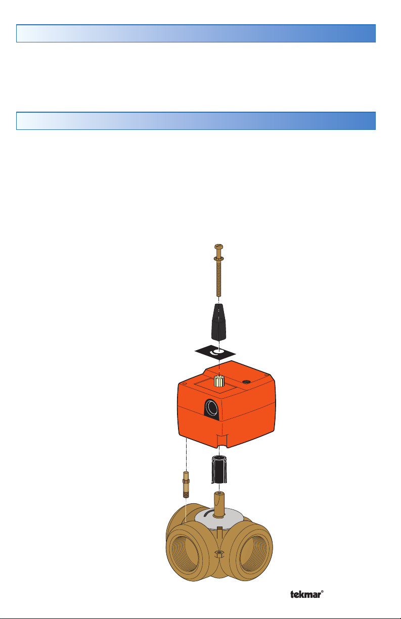
Step 2 - Mounting
Using a Phillips screwdriver, remove the two screws in the corners of the actuator
•
cover. Remove the cover.
Thread the anti-rotation bolt into one of the threaded holes on the mixing valve.
•
Do not align the anti-rotation bolt with the actuator motor corner cavity.
Install coupler onto mixing valve stem, ensuring that it is pushed all the way on.
•
Black coupler: for 3-way valves 710, 711, 712, 713, 714
•
White coupler: for 4-way valves 720, 721, 722, 723, 724
•
Install actuator body onto the coupler.
•
Screw
Handle
Scale Plate
Actuator Motor
Anti-Rotation Bolt
Mixing Valve
3 of 8
1
8
.
6
.
4
.
0
2
.
Corner Cavity
Coupler
Mixing Valve Stem
© 2013 742_D - 10/13
Page 4

Step 3 - Wiring
-------------------------------------------------------
-------------------------------------------------
--------------------------
Conduit Connector
Pull wires through conduit connector and provide enough wire length to connect
to wiring terminals. Tighten the conduit connector nut.
Power Supply
If using a 24 V (ac) power supply:
Connect C to terminal 1.
•
Connect R to terminal 2.
•
If using a 24 V (dc) power supply:
Connect the power supply negative (–) to terminal 1.
•
Connect the power supply positive (+) to terminal 2.
•
-------------------------------------------------------
Control Signal Input
Connect the analog 0-10 or 2-10 V (dc) control signal negative (–) to terminal 1.
•
Connect the analog 0-10 or 2-10 V (dc) control signal positive (+) to terminal 3.
•
Position Signal Output (may not be required)
Connect the position signal negative (–) to terminal 1.
•
Connect the position signal positive (+) to terminal 5.
•
-------------------------------------------------
--------------------------
R
C
1 2 3 5
– + Y U
Actuator
Motor
L
N
742
+ –
0-10 V (dc)
Control
Signal
4 of 8
© 2013 742_D - 10/13
Page 5

Step 4 - Switch Settings
------------------------------------------------------------
------------------------------------------------------------
Switch 1
Function Switch 1 Position
Counterclockwise to open valve Right (factory default)
Clockwise to open valve Left
Switch 2
Function Switch 2 Position
2-10 V (dc) signal Right (factory default)
0-10 V (dc) signal Left
------------------------------------------------------------
------------------------------------------------------------
CW CCW
0-10 V 2-10 V
5 of 8
© 2013 742_D - 10/13
Page 6

Step 5 - Final Assembly
•
Install actuator cover onto the actuator. Using a Phillips screwdriver, tighten the
two screws.
•
Install the scale plate.
•
For clockwise to open installations, face scale plate with 0 on the left and 1 on
the right.
•
For counterclockwise to open installations, face scale plate with 1 on the left
and 0 on the right.
•
Install actuator handle onto the actuator spline.
•
Install actuator screw through hole in the handle. Using a flat head screwdriver,
tighten until snug. Do not overtighten.
Testing and Troubleshooting
The actuator motor includes a manual override.
To engage manual operation, use a flat blade screwdriver and set the manual
override dial to the “hand” position.
Use the handle to manually adjust the valve position. When the handle is set to 0,
the valve should be closed and there should be no heat transfer. When the handle
is set to 1, the valve should be fully open and there should be heat transfer.
To return to automatic operation, use a flat blade screwdriver and set the manual
override dial to the “A” position.
Manual
override dial
6 of 8
.6
.4
.8
.2
0
1
© 2013 742_D - 10/13
Page 7

Technical Data
Actuating Motor 742 0-10 V (dc)
Literature 742_C, 742_D
Packaged weight 1.1 lbs (500 g)
Dimensions
Enclosure
Ambient conditions
Power supply
Control signal input
Position signal output
Angle of rotation
Motor speed
Rated torque
3-5/8" H x 3-1/8" W x 3-9/16" D (93 x 80 x 90 mm)
Polycarbonate plastic, NEMA type 1
Indoor use only, 32 to 122°F (0 to 50°C), 95% RH non-
condensing
24 V ± 10% (ac/dc), 2.5 VA, Class 2
0-10 V (dc) or 2-10 V (dc), selected by switch setting,
100 kΩ maximum input impedance
0-10 V (dc) or 2-10 V (dc), follows switch setting,
3 kΩ maximum load impedance
Electrically limited to 90° shaft rotation, clockwise or
counterclockwise direction selected by switch setting
140 seconds
88 in•lbs (10 N•m)
7 of 8
© 2013 742_D - 10/13
Page 8

Limited Warranty and Product Return Procedure
Limited Warranty The liability of tekmar under this warranty is limited. The Purchaser, by taking receipt
of any tekmar product (“Product”), acknowledges the terms of the Limited Warranty in effect at the time
of such Product sale and acknowledges that it has read and understands same.
The tekmar Limited Warranty to the Purchaser on the Products sold hereunder is a manufacturer’s passthrough warranty which the Purchaser is authorized to pass through to its customers. Under the Limited
Warranty, each tekmar Product is warranted against defects in workmanship and materials if the Product
is installed and used in compliance with tekmar’s instructions, ordinary wear and tear excepted. The passthrough warranty period is for a period of twenty-four (24) months from the production date if the Product is
not installed during that period, or twelve (12) months from the documented date of installation if installed
within twenty-four (24) months from the production date.
The liability of tekmar under the Limited Warranty shall be limited to, at tekmar’s sole discretion: the cost of parts
and labor provided by tekmar to repair defects in materials and / or workmanship of the defective product; or to
the exchange of the defective product for a warranty replacement product; or to the granting of credit limited to
the original cost of the defective product, and such repair, exchange or credit shall be the sole remedy available
from tekmar, and, without limiting the foregoing in any way, tekmar is not responsible, in contract, tort or strict
product liability, for any other losses, costs, expenses, inconveniences, or damages, whether direct, indirect,
special, secondary, incidental or consequential, arising from ownership or use of the product, or from defects in
workmanship or materials, including any liability for fundamental breach of contract.
The pass-through Limited Warranty applies only to those defective Products returned to tekmar during the warranty period. This Limited Warranty does not cover the cost of the parts or labor to remove or transport the defective Product, or to reinstall the repaired or replacement Product, all such costs and expenses being subject to
Purchaser’s agreement and warranty with its customers.
Any representations or warranties about the Products made by Purchaser to its customers which are different
from or in excess of the tekmar Limited Warranty are the Purchaser’s sole responsibility and obligation. Purchaser
shall indemnify and hold tekmar harmless from and against any and all claims, liabilities and damages of any
kind or nature which arise out of or are related to any such representations or warranties by Purchaser to its
customers.
The pass-through Limited Warranty does not apply if the returned Product has been damaged by negligence by persons other than tekmar, accident, fire, Act of God, abuse or misuse; or has been damaged by modifications, alterations or attachments made subsequent to purchase which have not been authorized by tekmar; or if the Product was
not installed in compliance with tekmar’s instructions and / or the local codes and ordinances; or if due to defective
installation of the Product; or if the Product was not used in compliance with tekmar’s instructions.
THIS WARRANT Y IS IN LIEU OF ALL OTHER WARRANTIES, EXPRESS OR IM PLIED, W HICH THE GOVERNING
LAW ALLOWS PARTIES TO CONTRACTUALLY EXCLUDE, INCLUDING , WITHOUT LIMITATIO N, IMPLIED WARRANTIES OF MERCHANTABILITY AND FITNESS FOR A PARTICULAR PURPOSE, DURABILITY OR DESCRIPTION OF THE PRODUCT, ITS NON-INFRINGEMENT OF ANY RELEVANT PATENTS OR TRADEMARKS, AND
ITS CO MPLI ANCE WITH OR NON-VIOLATION OF ANY APPLI CABLE EN VIRO NMENTAL , HEA LT H OR SAFETY
LEGISLATION; THE TERM OF ANY OTHER WARRANTY NOT HEREBY CONTRACTUALLY EXCLUDED IS LIMITED SUCH THAT IT SHALL NOT EXTEND BEYOND TWENTY-FOUR (24) MONTHS FROM THE PRODUCTION
DATE, TO THE EXTENT THAT SUCH LIMITATION IS ALLOWED BY THE GOVERNING LAW.
Product Warranty Return Procedure All Products that are believed to have defects in workmanship or materials must be returned, together with a written description of the defect, to the tekmar Representative assigned to
the territory in which such Product is located. If tekmar receives an inquiry from someone other than a tekmar
Representative, including an inquiry from Purchaser (if not a tekmar Representative) or Purchaser’s customers,
regarding a potential warranty claim, tekmar’s sole obligation shall be to provide the address and other contact
information regarding the appropriate Representative.
WARNING: This product contains chemicals known to the State of California to cause cancer and birth defects or
other reproductive harm. For more information: www.watts.com/prop65
Product design, software and literature are Copyright ©2013 by tekmar Control Systems Ltd.,
A Watts Water Technologies Company. Head Offi ce: 5100 Silver Star Road, Vernon, B.C.
Canada V1B 3K4, 250-545-7749, Fax. 250-545-0650
All specifications are subject
to change without notice.
8 of 8 742_D - 10/13.
Web Site
: www.tekmarControls.com
 Loading...