

Page 1
- Data Brochure
•
•
•
•
•
Indoor Sensor 084
The tekmar Indoor Sensor 084 includes a 10 k thermistor mounted
on a white thermoplastic disk to provide an accurate measurement
of the indoor temperature. The 084 mounts flush or nearly flush to
the wall to give an unobtrusive look to the sensor. Since the sensor
material is corrosion resistant, drywall installers are able to mud
over the sensor or the 084 can be painted to match the existing
wall color. The 084 can be connected to a tekmar thermostat for
remote temperature sensing.
Actual Size
D 084
05/07
Installation
CAUTION
Improper installation and operation of this sensor could result in damage to equipment and possibly even personal injury. It is your
responsibility to ensure that this sensor is safely installed according to all applicable codes and standards. Please follow these step-bystep instructions to gain a full understanding of this device.
STEP ONE
GETTING READY
Check the Contents
Check the contents of this package. If any of the contents listed are missing or damaged, please refer to the Limited Warranty and
Product Return Procedure on the back of this brochure and contact your wholesaler or tekmar sales representative for assistance.
Type 084 includes
STEP TWO
The Indoor Sensor should be installed on an interior wall of the desired zone to be controlled. Avoid installing the sensor in a wall
if the adjacent zone is at a much different temperature. Do not mount the 084 in a location that may be affected by localized heat
sources or cold drafts (in direct sunlight or near a supply air duct or window).
STEP THREE
•
Before drywall is installed run two conductor 18 AWG wire from
the tekmar thermostat to the desired location of the Indoor
Sensor. The maximum wire length between a thermostat and
sensor is 500’ (152.4 m).
•
Do not run the wires parallel to telephone or power lines. If
the Indoor Sensor wires are located in an area with strong
sources of electromagnetic noise, shielded cable or twisted pair
should be used or the wires can be run in a grounded metal
conduit. If using shielded cable, one end of the shield wire
should be connected to the Com terminals on the thermostat
and the other end should remain free. The shield must not be
connected to earth ground.
One Indoor Sensor 084 • One Data Brochure D 084.
CHOOSING A LOCATION FOR THE INDOOR SENSOR
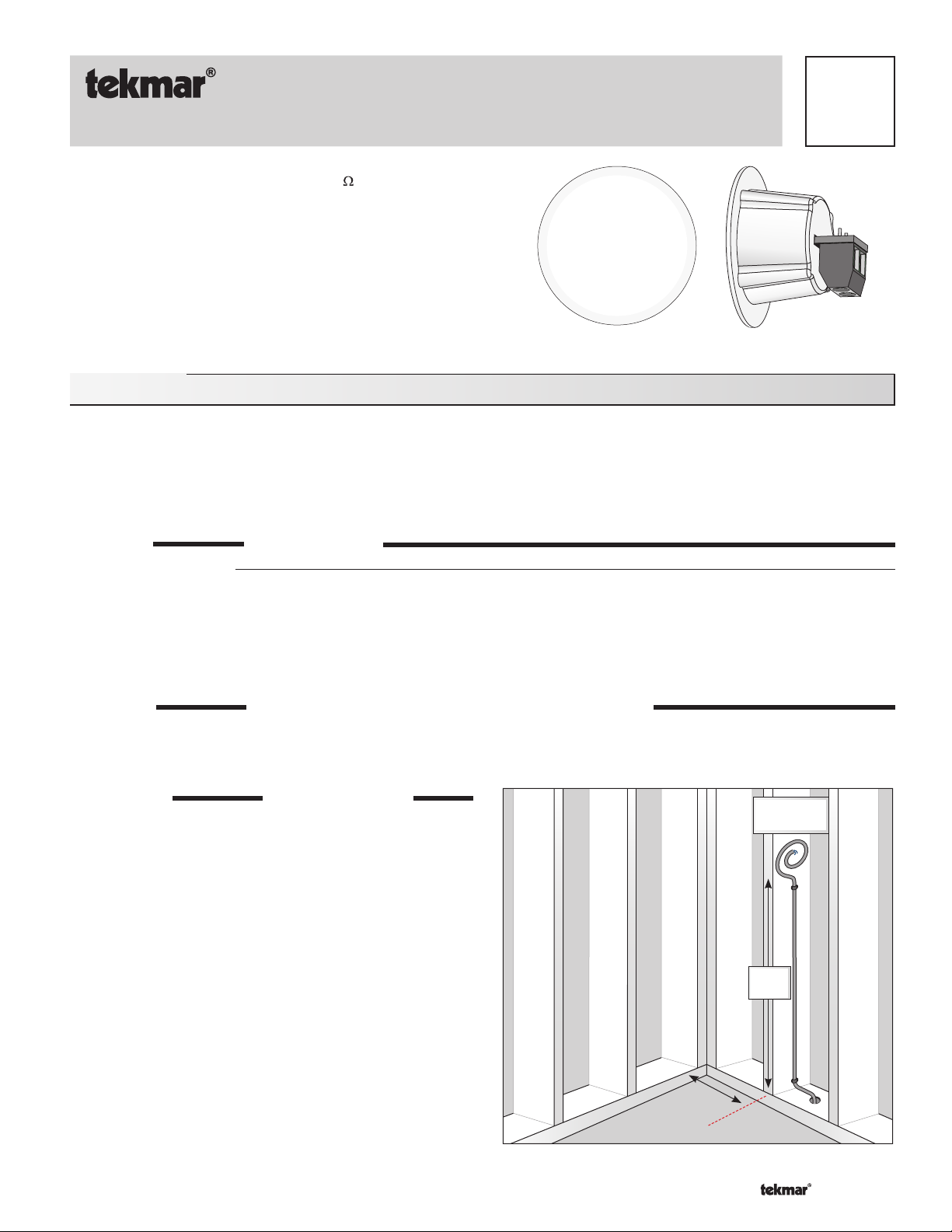
ROUGH IN WIRING
1’ (.3 m) of
excess wire
5’
(1.5 m)
•
Staple the wire to a wall stud 5’ (1.5 m) above the floor and
coil 1’ (.3 m) of the wire to work with before cutting it off.
• Write down the exact location of the wire in the wall so it
can be found when the drywall is installed.
Record distance from corner.
1 of 4
© 2007 D 084 - 05/07
Page 2
STEP FOUR
••
••
••
••
••
••
••
••
••
••
•
•
•
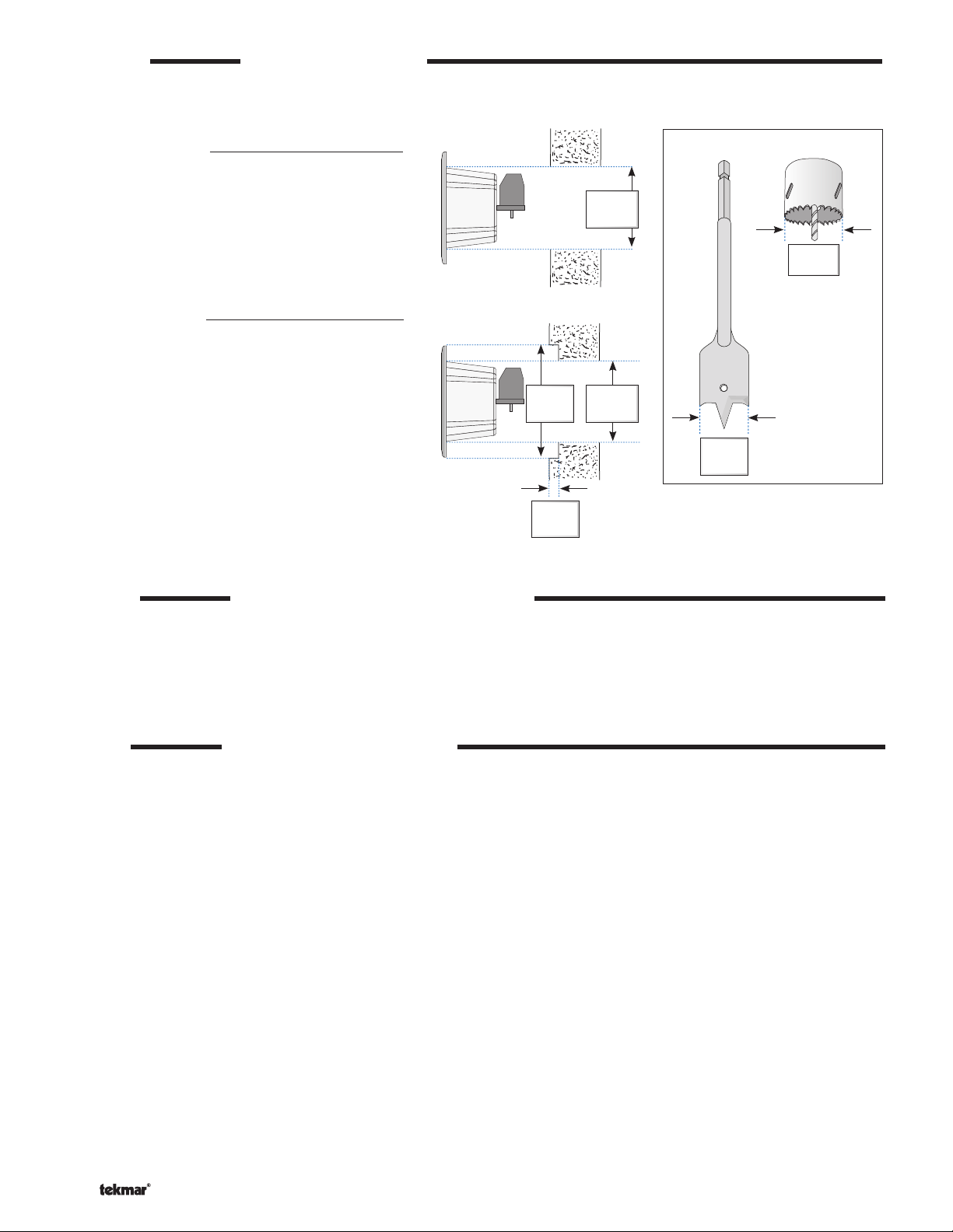
PREPARING THE WALL
Once the drywall has been installed, locate the sensor wire behind the drywall using your notes from step three.
Near Flush Mount
Using a hole-saw, drill a 1” (25.5 mm) hole at the
location of the sensor wire.
Pull the excess wire through the hole and now you
are ready to wire your sensor.
Do not drill hole directly over stud.
True Flush Mount
Using a 1-1/2” (38.0 mm) spade bit, drill a recess
hole lightly into the drywall to a depth no more than
1/8” (3.0 mm).
Turn the 084 Indoor Sensor around so that the front
disk is facing the wall and test to see if this recess
hole is deep enough to mount the sensor flush.
Once the recess hole is at the desired depth, use a
1” (25.5 mm) hole-saw and place the guide bit into
the center hole created by the spade bit and drill
through the drywall.
Pull the excess wire through the hole and now you
are ready to wire your sensor.
1-1/2”
(38.0 mm)
1/8”
(3.0 mm)
1”
(25.5 mm)
1”
(25.5 mm)
Spade Bit
1-1/2”
(38.0 mm)
Hole Saw
1”
(25.5 mm)
STEP FIVE
Connect the two wires to the terminals in the back of the 084 sensor.
Once wired, feed the excess wire back into the hole and hand press the 084 until the back of the disk touches the wall. The sensor
WIRE & MOUNT THE INDOOR SENSOR
is held in place by the taper of the enclosure (no fasteners required).
Be careful not to press the sensor through the drywall.
STEP SIX
• The sensor can now be painted to match the wall color or wallpapered over.
• The sensor can also be mudded over and sanded during the drywall process, and then the wall can be painted or wallpapered
FINISH THE INDOOR SENSOR
as normal. Be careful not to sand the sensor plate.
• Keep a record of where the 084 is installed in case of failure the sensor can be found.
Note: The mud area of a near flush mount will be much greater than the mud area of a true flush mount.
2 of 4
© 2007 D 084 - 05/07
Page 3

Sensor Testing Instructions
A good quality test meter capable of measuring up to 5,000 k (1 k = 1000 ) is required to measure the sensor resistance. In addition
to this, the actual temperature must be measured with either a good quality digital thermometer, or if a thermometer is not available, a
second sensor can be placed alongside the one to be tested and the readings compared.
First measure the temperature using the thermometer and then measure the resistance of the sensor at the control. The wires from the
sensor must not be connected to the control while the test is performed. Using the chart below, estimate the temperature measured by
the sensor. The sensor and thermometer readings should be close. If the test meter reads a very high resistance, there may be a broken
wire, a poor wiring connection or a defective sensor. If the resistance is very low, the wiring may be shorted, there may be moisture in
the sensor or the sensor may be defective. To test for a defective sensor, measure the resistance directly at the sensor location with the
wires disconnected.
Note: Do not apply voltage to a sensor at any time as damage to the sensor may result.
Temperature Re sistance
°F °C
-50 -46 490,813
-45 -43 405,710
-40 -40 336,606
-35 -37 280,279
-30 -34 234,196
-25 -32 196,358
-20 -29 165,180
-15 -26 139,402
-10 -23 118,018
-5 -21 100,221
0 -18 85,362
5 -15 72,918
10 -12 62,465
15 -9 53,658
Temperature Re sistance
°F °C
20 -7 46,218
25 -4 39,913
30 -1 34,558
35 2 29,996
40 4 26,099
45 7 22,763
50 10 19,900
55 13 17,436
60 16 15,311
65 18 13,474
70 21 11,883
75 24 10,501
80 27 9,299
85 29 8,250
Temperature Re sistance
°F °C
90 32 7,334
95 35 6,532
100 38 5,828
105 41 5,210
110 43 4,665
115 4 6 4 ,18 4
120 49 3,760
125 52 3,383
130 54 3,050
135 57 2,754
140 60 2,490
145 63 2,255
150 66 2,045
155 68 1,857
Temperature Re sistance
°F °C
160 71 1,689
165 74 1,538
170 77 1,403
175 79 1,281
180 82 1,172
185 85 1,073
190 88 983
195 91 903
200 93 829
205 96 763
210 99 703
215 102 648
220 104 598
225 107 553
3 of 4
© 2007 D 084 - 05/07
Page 4

Technical Data
Indoor Sensor 084
Literature D 084
Packaged weight 0.11 lbs (50g)
Enclosure White PC-ABS plastic
Dimensions 1-7/16” O.D. x 1-1/8” D (36 O.D. x 28 mm)
Approval CSA C US, CSA/UL 61010-1
Ambient Conditions Indoor use only, -60 to 140°F (-50 to 60°C), < 90% RH non-condensing
Sensor Type NTC thermistor, 10 k
@ 77°F (25°C ± 0.2°C), ß = 3892
Limited Warranty and Product Return Procedure
Limited Warranty The liability of tekmar under this warranty is limited. The
Purchaser, by taking receipt of any tekmar product (“Product”), acknowledges the terms of the Limited Warranty in effect at the time of such Product
sale and acknowledges that it has read and understands same.
The tekmar Limited Warranty to the Purchaser on the Products sold hereunder
is a manufacturer’s pass-through warranty which the Purchaser is authorized to
pass through to its customers. Under the Limited Warranty, each tekmar Product is warranted against defects in workmanship and materials if the Product
is installed and used in compliance with tekmar’s instructions, ordinary wear
and tear excepted. The pass-through warranty period is for a period of twentyfour (24) months from the production date if the Product is not installed during
that period, or twelve (12) months from the documented date of installation if
installed within twenty-four (24) months from the production date.
The liability of tekmar under the Limited Warranty shall be limited to, at tekmar’s
sole discretion: the cost of parts and labor provided by tekmar to repair defects in
materials and / or workmanship of the defective product; or to the exchange of the
defective product for a warranty replacement product; or to the granting of credit
limited to the original cost of the defective product, and such repair, exchange or
credit shall be the sole remedy available from tekmar, and, without limiting the
foregoing in any way, tekmar is not responsible, in contract, tort or strict product liability, for any other losses, costs, expenses, inconveniences, or damages,
whether direct, indirect, special, secondary, incidental or consequential, arising
from ownership or use of the product, or from defects in workmanship or materials,
including any liability for fundamental breach of contract.
The pass-through Limited Warranty applies only to those defective Products
returned to tekmar during the warranty period. This Limited Warranty does not
cover the cost of the parts or labor to remove or transport the defective Product, or
to reinstall the repaired or replacement Product, all such costs and expenses being
subject to Purchaser’s agreement and warranty with its customers.
Any representations or warranties about the Products made by Purchaser to its
customers which are different from or in excess of the tekmar Limited Warranty are
the Purchaser’s sole responsibility and obligation. Purchaser shall indemnify and
hold tekmar harmless from and against any and all claims, liabilities and damages
of any kind or nature which arise out of or are related to any such representations
or warranties by Purchaser to its customers.
The pass-through Limited Warranty does not apply if the returned Product has
been damaged by negligence by persons other than tekmar, accident, fire, Act
of God, abuse or misuse; or has been damaged by modifications, alterations or
attachments made subsequent to purchase which have not been authorized by
tekmar; or if the Product was not installed in compliance with tekmar’s instructions
and / or the local codes and ordinances; or if due to defective installation of the
Product; or if the Product was not used in compliance with tekmar’s instructions.
THIS WARRANTY IS IN LIEU OF ALL OTHER WARRANTIES, EXPRESS OR
IMPLIED, WHICH THE GOVERNING LAW ALLOWS PARTIES TO CONTRACTUALLY EXCLUDE, INCLUDING, WITHOUT LIMITATION, IMPLIED WARRANTIES
OF MERCHANTABILITY AND FITNESS FOR A PARTICULAR PURPOSE, DURABILITY OR DESCRIPTION OF THE PRODUCT, ITS NON-INFRINGEMENT OF
ANY RELEVANT PATENTS OR TRADEMARKS, AND ITS COMPLIANCE WITH
OR NON-VIOLATION OF ANY APPLICABLE ENVIRONMENTAL, HEALTH OR
SAFETY LEGISLATION; THE TERM OF ANY OTHER WARRANTY NOT HEREBY
CONTRACTUALLY EXCLUDED IS LIMITED SUCH THAT IT SHALL NOT EXTEND
BEYOND TWENTY-FOUR (24) MONTHS FROM THE PRODUCTION DATE, TO
THE EXTENT THAT SUCH LIMITATION IS ALLOWED BY THE GOVERNING
LAW.
Product Warranty Return Procedure All Products that are believed to have
defects in workmanship or materials must be returned, together with a written
description of the defect, to the tekmar Representative assigned to the territory in
which such Product is located. If tekmar receives an inquiry from someone other
than a tekmar Representative, including an inquiry from Purchaser (if not a tekmar
Representative) or Purchaser’s customers, regarding a potential warranty claim,
tekmar’s sole obligation shall be to provide the address and other contact information regarding the appropriate Representative.
tekmar Control Systems Ltd., Canada
Control Systems
tekmar Control Systems, Inc., U.S.A.
Head Office: 5100 Silver Star Road
Vernon, B.C. Canada V1B 3K4
(250) 545-7749 Fax. (250) 545-0650
Web Site: www.tekmarcontrols.com
Product design, software and literature are Copyright © 2007 by:
4 of 4
tekmar Control Systems Ltd. and tekmar Control Systems, Inc.
All specifications are subject to change without notice.
Printed in Canada. D 084 - 05/07.
 Loading...