


TECHNICAL BULLETIN 10th Sep 1999
MODEL:
PROBLEM:
EU-34T (AK20 CHASSIS)
“White Dot Noise” pattern visible on low RF signal input.
File: EU-34T (Whitedot).doc / EU-34T (Whitedot).pdf
White dot noise pattern occurs when signal RF input is too low. This modification will improve the signal/noise
vastly.
Instructions:
1. Remove C820 (Ceramic Cap 270pF 1KV)
2. Insert (Ceramic Cap 470pF 1KV) into location C820
3. Add a 0.22nF 630V capacitor in parallel with D806.
Regards,
Fabian Lubanovic
TEAC Australia Pty Ltd.
Page 1 of 1

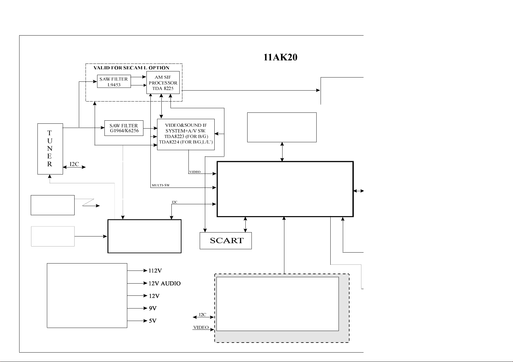
11AK20 CHASSIS CIRCUIT DESCRIPTION
1. GENERAL INFORMATION :
This document provides detailed information about the fully I2C controlled Television Chassis named 11AK20.
11AK20 is based on the bus controlled circuits in which all the filters, traps and delay lines have been integrated.
Therefore the numbers of external components are reduced and the user, service and factory adjustments are made
through I2C BUS control.
This chassis has been designed mainly for the 90°, 14 and 15 picture tubes.
This chassis has a SMPS circuitry which has been designed to get low stand-by power consumption
(less than 3W) as an option. On the other hand, it also has wide range (90-270V 50/60 Hz) mains as an option.
The chassis covers almost all the existing worldwide transmission and colour standards as PAL B/G/I/M/N,
SECAM B/G/D/K/K/L/L and NTSC M (3.58), NTSC (4.43) using same Main Printed Circuit Board by means of
optional components and settings. Tuning system is Voltage Synthesized for all systems Except NTSC M and
PAL M/N applications but it is Frequency Synthesized for NTSC M and PAL M/N applications.
Furthermore, chassis has also European Wide-range teletext solution as an option. This solution supports all
the European teletext standards optionally as 1 page normal, fast and top text modes.
The chassis has Euro AV Plug (Scart Socket) for Peritel and SVHS connections. The pictures in 16 - 9 format can
be displayed via this Peritel connection. Other optional external connections are front AV input RCA jacks, back AV
output RCA jacks and Headphone jack.
The software has been developed with a menu driven user interface supporting all possible chassis versions
with a storage capacity of 100 programs.
2. IF STAGE :
The inputs for IF stage are IF inputs from Tuner to produce front-end Video and Audio, Video and Audio from
Scart or front AV RCA jack to be able to select the internal or external video and audio according to the control
signals which comes from microcontroller and STV 2118. Then, the resultant video and audio signals are sent to
video processing stage and audio output stage, respectively. Furthermore, front-end video and audio signals are sent
to scart and or back AV RCA jacks. This part also produces some control signals for tuner and microcontroller.
This stage was designed for processing positive (optional) and negative modulated mono and one scart
applications.
STV 8223 is the IF IC that is used in only negative modulation. There is an alignment which is the VCO
adjustment (VL101). The procedure of alignment can be described briefly as follows :
The IF signal is applied to the IF inputs in accordance with the standards (for B/G 38.9MHz) at pin # 1 and 2 of
SAW filter (Z101).
Adjust the VL101 until getting 2.5 Vdc at pin # 9 of uC (IC501).
This stage is also used for negative and positive modulated, mono applications. STV 8224 (negative and positive
modulation and FM sound) (IC 101) and STV 8225 (AM sound) (IC102) are the IF ICs.
There are two alignments in this case, which are the VCO adjustment (VL101) for B/G - L standards and VC101 for
L standard. The procedure of the alignments can be described briefly as follows :
The system is Switched to B/G standard reception,
The IF signal is applied to the IF inputs in accordance with the standards (for B/G 38.9MHz) at pin # 1 and 2 of
SAW Filter Z101.
Adjust the VL101 until getting 2.5 Vdc at pin # 9 of uC.
The system is Switched to L standard reception,
The IF signal is applied to the IF inputs in accordance with the standards (for L 33.9MHz) at pin # 1 and 2 of
SAW Filter Z101.
Adjust the VC101 until getting 2.5 Vdc at pin # 9 of uC.
2.1 Video and Sound IF System & Switch IC STV8223:
STV 8223 is a picture and sound IF processor for negative application. The architecture of the video and sound
demodulator, which are both based on PLL structure, allows a very good linearity of the Intermediate Frequency
Response and an application with very few external components and adjustments.
The volume on the audio signal is controlled through a DC level (pin # 13) which is provided from
STV 2112/2116/2118 where all the I2C decoding is realized.
STV 8223 also provides the audio and video switches for scart - AV applications.
The IF inputs at pins # 19 and # 20 are driven by Tuner via Saw filter (Z101). The baseband signal produced from
these IF inputs appears at pin # 3. This signal is used to produce sound trapped video signal and intercarrier sound signal.
For multi-standard models, a switched trap circuitry is used (Q103, Q104, Q105). This internal video signal is fed to
pin # 10 of this IC for internal-external (coming from scart) video switching and to the base of the buffer transistor Q102
for the video output of the scart connector. The intercarrier signal used for reproducing sound, passes through the
band pass filter Z103 with center frequency 5.5MHz for B/G standard or Z104 for I (6.0MHz) or Z105 for D/K (6.5MHz)
or Z106 for M/N (4.5MHz) in according to selected system by intercarrier signal switching circuitry (D106, D107,
D108, D109, D110) and resultant signal is applied to the pin #8 of the IC which is the input of limiter and SIF PLL stage.
1

The switch control signal is supplied by microcontroller. The limiter and SIF PLL output pin # 15 which is connected to
the deemphasis capacitor drives audio out of the scart connector and AV jack. The external inputs of IC, which are pin
# 12 for video and pin # 16 for audio, are connected to the related scart connector inputs or AV RCA jack inputs.
The internal-external signal selection for monitoring is made by control voltage at pin # 8 produced by STV 2118.
The selected video at pin # 11 drives video processing stage. On the other hand, the selected audio is processed in
volume control stage in according with DC control voltage at pin # 13 and then, it is sent from pin # 14 to sound
output stage.
The IF block produces control signals, which are AGC for tuner at pin # 23 in according to voltage of pin
# 24 controlled by microcontroller pin # 2.
2.2 Multi-Standard Video and Sound IF System & Switch IC STV 8224 and AM SIF IC STV 8225 :
STV 8224 is a picture and sound IF processor for negative and positive applications. The architecture of the
video and sound demodulator, which are both based on PLL structure, allows a very good linearity of the Intermediate
Frequency Response and an application with very few external components and adjustments.
The volume on the audio signal is controlled through a DC level (pin #13) which is provided from
STV 2112/2116/2118 where all the I2C decoding is realized.
STV 8224 also provides the audio and video switches with STV 8225 for one scart applications.
The IF inputs at pins # 19 and # 20 are driven by Tuner via SAW filter (Z101) which is K6256 for B/G - L/L
applications. This saw filter is switchable according to the control signals produced by microcontroller.
The baseband signal at pin # 3 is produced from these IF inputs according to the control signal at pin # 4.
This control signal comes from STV 2118 Multi-Switch Output according to the selected system standard.
The baseband signal is used to produce sound trapped video signal and on the other hand to produce intercarrier
sound signal for B/G standard. This internal video signal is fed to pin # 10 of this IC for internal-external
(coming from scart) video switching and to the base of the buffer transistor Q102 for the video output of the scart
connector. For the internal and external video switching, external video enters from pin #12, and then, selected video
is sent from pin # 11 to video processing part.
The intercarrier signal used for reproducing sound, passes through the band pass filter Z103 with center frequency
5.5MHz for B/G standard and resultant signal is applied to the pin # 8 of the IC STV 8224 which is the input of limiter
and SIF PLL stage. The limiter and SIF PLL output pin # 15 which is connected to the deemphasis capacitor drives
pin # 5 of the IC STV 8225 as FM Sound Input in order to be able to select the appropriate (FM or AM) audio signal
for producing audio out of the scart connector. The selected signal at pin # 9 of STV8225 drives external audio
output connections. On the other hand, the audio switch in STV 8224 is used to select the internal FM signal or the output
of STV 8225 (pin # 7), which selects the internal AM signal or External audio signal (at pin # 11) coming from scart socket.
The selected audio is processed in volume control stage in according with DC control voltage at pin # 13 and then, it is sent
from pin # 14 to sound output stage. The IF signal is filtered at Z102 saw filter which is switchable according to the
control signals produced by microcontroller for L or L mode. Output of SAW is connected to pin # 1 and 14 of SIF IC
STV 8225(IC 102) for AM sound producing. The audio switches in STV 8225 selects the signals according to DC voltage
at # 10 of STV 8225 .
The IF block produces control signals, which are AGC for tuner at pin # 23 in according to voltage of pin # 24
controlled by microcontroller and AFC for microcontroller at pin # 2.
There are two main switching circuits. First one is the VCO Frequency Switching circuit and the second one is
the Saw Filter Switching circuit which covers both Video and Sound saw filters.
The control voltage for VCO switching circuitry is the L/L signal produced by microcontroller. The logic of this signal,
which is defined by MAC-15, is as given in Table 2.1.
Table 2.1 The Logic of the L/L Switching Voltage (based on MAC-15)
Selected Mode L/L Switching Voltage Adjusted Frequency
Modes other than L HIGH 38.9 MHz
L LOW 33.9 MHz
This control voltage is applied to R121. When this voltage is LOW, diode D105 is ON and VC101, C129 and
C130 are connected in parallel to the reference tank circuit VL101. On the other hand, This circuit is disconnected
when L/L voltage is HIGH since D105 is OFF.
In according to selected system configuration, it must be used multistandard switched type SAW filters.
For this reason an optional circuitry is applied this stage by D101, D102, (and if using L/L, D103 ,D104 for SIF SAW Z102).
3. SIGNAL PROCESSING PART :
This part processes video coming from IF part, RGB coming from Scart, Teletext and Controller in order to
drive Horizontal and Vertical deflection stages and CRT baseboard and to produce some control voltages by means of
Bus-controlled PAL-SECAM-NTSC TV Processor IC, STV 2112/2116/2118 and 64msec Delay Line IC, STV2180.
The detailed functional descriptions of these ICs are given in the following subsections.
2

3.1 Bus-controlled Multi-Standard TV Processor IC, STV 2118 :
The STV 2118 (IC 401) is a fully bus controlled IC for TV Luma, Chroma and Deflection processing. In order to
make the alignments by microcontroller via I2C, the required data are transferred from microcontroller into the
related registers of STV 2118. The main input for this IC are as follws :
I2C Inputs from microcontrolle
Y/CVBS Input from IF Part, external CVBS coming from scart or front AV RCA jack, external RGB and Fast
Blank signals coming from Scart, R input is also used for Chroma input in SVHS Mode
OSD and TELETEXT RGB and Fast Blank signals coming form both microcontroller and teletext processor IC
BCI (Black Current Information) coming from CRT Baseboard
BCL (Beam Current Limiting) information from Horizontal Output Stage
Line Flyback Sample coming from Horizontal Output Stage
Delayed R-Y and B-Y signals coming from Delay Line IC STV 2180
Detailed Features and the internal block diagram of the IC STV 2118 are given in following subsections:
3.1.1 Deflection Circuit :
The deflection part includes a fully integrated sync-separator locked to a 500 kHz VCO with external resonator
(X401), two phase locked loops for horizontal deflection, vertical count down with 50 Hz and 60 Hz operation for field
frequency.
Vertical output pulse is 10.5 lines long at pin # 35, furthermore horizontal output pulse is 28 msec on open
collector pin # 36.
The horizontal output is at high level when Vcc increases from 0V to 6.8V. On shutting down, the horizontal pulse
disabled when Vcc is below 6.2V.
When vertical pulses are disappeared, horizontal output is disabled by microcontroller for keeping CRT phosphor.
Line position adjustment is controlled by bus using related service mode.
Bus controlled output voltage at pin # 34 is used to adjust vertical amplitude at vertical output stage via R705,
R706 and R707.
Bus controlled vertical position information is produced from high level of the vertical pulse pin # 35 and this
signal is used to adjust vertical positioning at vertical output stage via R701, R703, R704, C701, D701 and Q701.
The sandcastle signal at pin # 37 is used to control the external baseband chroma delay line
(STV 2180 -IC 402- pin # 6).
3.1.2 Filters :
All filters (integrated trap filter, integrated chroma bandpass, integrated bell filter for SECAM, integrated delay line)
are tuned with a reference PLL.
The PLL consists of a lowpass filter, a phase comparator, a loop filter (an external capacitor C423 on pin # 8).
The reference signal is the continuous carrier wave from the VCO (4.43 MHz or 3.58 MHz). The PLL will adjust the
center frequency of the lowpass so that it will be equal to the reference signal. The tuning voltage of the PLL
(memorized on pin # 8) will adjust all other filters.
The cloche filter is fine-tuned with a second PLL operating during frame retrace. Tuning voltage is memorized on an
external capacitor C424 at pin # 9.
3.1.3 Video Circuit :
Video part includes two RGB inputs, automatic cut-off control, DC cut-off adjustment, RGB gain adjustments,
beam current limiting. Furthermore, user video settings (contrast, saturation, brightness and sharpness controls)
are performed by this block. RGB output pins are as follows: R output is pin # 29, G output is pin # 28 and B output
is pin # 27.
The beam current information is fed to pin # 31 via R411 and D403. This control voltage will act on contrast first,
then the brightness will be decreased when contrast attenuation reaches -5dB.
Automatic cut-off function is realized according to the BCI information at pin # 30. Sequential cut-off current
measurements are made during three lines after frame blanking signal.
3.1.4 Chroma Circuit :
The chroma part includes PAL, SECAM, NTSC demodulator. An external base band delay line (STV 2180 IC402)
is used in this concept. R-Y and B-Y outputs of STV 2118 (pin # 40 and pin # 41) are sent to STV 2180 to get 64msec
delayed signals.
The PAL, SECAM or NTSC standard selection is made by automatic standard identification.
Three Xtals for PAL M (X404), PAL N (X405) and NTSC M (X403) and their switching circuitry (Q401, Q402, Q403,
Q404, D401, D402) are used in PAL M/N and NTSC M models only.
SVHS selection is made by microcontroller via bus control.
3
3.1.5 Other Functions :
Volume Control and Mute output is pin # 10. The voltage range for volume control is 0.5V to 5V, whereas below
0.1V is used for muting. The output of this pin is controlled by microcontroller via bus and the value is saved in related
register of the STV 2118.
The selection of the IF standard (Positive or Negative Vision Modulation) and the TV / SCART(AV) mode is
controlled by bus. The selection is converting in four voltages which are used to control the IF ICs STV 8224 and
STV 8225 on pin # 11. Related voltage levels and their situations are tabulated as follows:
Table 3.1 Related voltage levels and their situations for pin # 11 of STV 2118.
SITUATION VOLTAGE RANGE (V11)
STANDARD SOURCE MIN. MAX.
NEGATIVE TV 0 0.7
POSITIVE TV 2.9 3.8
POSITIVE SCART 5.2 6.1
NEGATIVE SCART 7.88 9
3.2 Base Band Chroma Delay Line IC STV 2180 :
The STV 2180 is an integrated base band chroma delay line with one line delay, which has been designed to
match chroma decoders with color difference signal outputs (R-Y) and (B-Y). This IC has dual switched capacitors
delay line with 3 MHz clock and integrated filters to suppress the residual clock components. It designed to work in
conjunction with STV 2112/2116/2118 and it allows an adjustment free application.
The inputs for this IC are as follows :
(R-Y) at pin # 2 coming from STV 2118
(B-Y) at pin # 14 coming from STV 2118
Sandcastle Pulse at pin # 6 coming from STV 2118
On the other hand, outputs of this IC are as follows :
Delayed (R-Y) at pin # 3
Delayed (B-Y) at pin # 4
4. HORIZONTAL OUTPUT AND EHT STAGE :
The horizontal pulses, from pin #36 of IC401, are connected to base of driver transistor Q601 through Q601,
R603, C601. The driver circuitry (Q601, R604, C602, L602, R608) drives the horizontal deflection output transistor
BU808DFI (Q602). TR601 is the EHT (Extra High Tension) transformer. The 112V supply voltage for the stage is
connected at # 2. TR601 transformer generates EHT, focus and G2 voltages, required by picture tube. Furthermore,
the 200V supply for video output, 26V supply for vertical output and heater drive current are derived from this
transformer. The beam current information from pin #8 of TR601 is used for reducing the contrast at excessive long
term average beam current and compensation voltage to vertical output to stabilize picture height. The flyback signal
sample (AC coupled and clipped by R606, C614, C604, D602, D601) is used to generate sandcastle pulse for video
processor IC and horizontal pulse (Q603) required by uC.
5. VERTICAL OUTPUT STAGE (TDA 1771)
The TDA1771 (IC701) vertical deflection integrated circuit is used for output of vertical stage. Trigger pulses from
STV2118 feeds to pin # 3 of TDA1771. The signal produced by built in ramp generator synchronizes input trigger pulses.
Amplitude is adjusted by an independent input pin (# 4). Built in voltage generator output, feedback information by pin # 8,
internal sawtooth signal and amplitude information are applied to output OP-AMP. This output stage has also thermal
protection and flyback generator for reliability and effectivity. Applied pulse from STV2118, contains vertical position
information as maximum dc level of signal and is extracted by Q701 and fed as a part of feedback to output stage.
Vertical shift DC supply is obtained via R716. The amplitude control is supplied by STV2118. Vertical deflection output
stage is supplied by +26V output of FBT and D605, C603 circuitry.
6. SOUND OUTPUT STAGE (TDA2822M) :
TDA2822M is used as the AF output amplifier. It is supplied by +12V coming from a separate winding in the SMPS
transformer (T802). Pin #14 of the STV8223 ( or STV 8224) is AC coupled to the input pin #7 of the TDA2822M via a
resistor divider. Maximum audio output power at 10% THD is 1.5W. Q301 for start up muting and Q302 for muting by uC
are used, and an alarm signal by uC is fed to this input.
4

7. POWER SUPPLY (SMPS) :
The DC voltage sources required at various stages of the chassis are provided by an SMPS controlled by the
IC801 (MC44603 for common models and MC44604 for low power consumption on stand by mode models).
This IC is designed for driving, controlling and protecting the switching MOSFET transistor of SMPS (Q801).
This supply has three outputs; one 112V output which is used for horizontal output and 33V generation needed by
tuner section, one 16V output for all small signal sections an uC and one for audio output section. This chassis may
be used in 90 - 270 volt with appropriate optional circuitry and components. The uC which is supplied by a source
designed regulator with zener diode (D814) controls stand by mode by switching Q803 (for 44604 application Q806).
8. uC (MICROCONTROLLER) :
The microcontroller hardware that is member of the ST6 family has a TV receiver control software with menu
control. It controls the chassis through IIC bus, PWM outputs and I/O ports. Dominant features of controller are control
of optional teletext, outputs for OSD, IR control signal receiving, and internal EEPROM.
The controller has IIC communication port at # 40 , # 41 and OSD driver (R,G,B,FBl) at # 22, # 23, # 24, # 25.
PWM control outputs are tuning # 34; vertical linearity adjustment # 1; AGC adjustment # 2. Other control outputs are
Muting - video ident # 3; led driver # 4; system switches # 5, # 6, # 8, # 19, # 20, # 36; tuner switches # 18, # 19 and
inputs are AFC information from IF # 9; keyboard # 10, # 11, # 13, # 14; scart mode ident (4/3-16-9) # 38, # 39;
horizontal sync # 26; vertical # 27; infrared # 35 and reset # 33.
The uC starts system according to option diodes configuration (D501, D503, D505, D506, D508).
The controller has also a software which is able to control some service adjustments: R,G,B gain; R,G cut off;
vertical position; vertical linearity; horizontal position; vertical amplitude; AGC; language selection for teletext.
For enter to service mode followed procedure must be act within four seconds:
1- Press volume down button on the keyboard;
2- Press prog button on the R/C hand set;
3- Press - - button on the R/C hand set;
4- Press TV button on the R/C hand set;
Parameters can be sellected by program up and down, parameter adjustments can be done by volume up and
down buttons. Memorizing the adjusted parameters can be done by pressing red button. For exit from service mode
Press TV button.
9. TELETEXT :
The video signal coming from IF stage is fed to Data Slicer IC001. Then, there are two possibilities for decoding part;
CF70095 or CF70195 for 1-Page simple text applications and CF7020X family for fastext and toptext applications.
Finally, R, G, B and FBL signals are sent to the related inputs of STV2118.
The alignment procedure for CF70095 or CF70195 application is as following:
1- Apply a video with teletext transmission and select for teletext.
2- Adjust the coil (VL001) for the voltage at pin # 28 2.5V.
10. CRT BASE-BOARD :
When RGB signals enter the input of the video amplifier stage (CRT base-board), they are amplified by means
of three symmetrical video amplifier stages. For this purpose three 2SC2482 high voltage, video output transistors
are used. So, high gain-bandwidth product is achieved. Furthermore black level changes at the output amplifiers
caused by temperature or component agings are compensated by means of a closed loop control system.
For this reason the cathode current information (ICAT) is sent to STV2118.
5
$8',228
0
9$/,')256(&$0/237,21
6$:),/7(5
/
$06,)
352&(6625
7'$
%/2&.',$*5$02)7+(
&+$66,6
7'$
'(/$</,1(
679
7
8
6$:),/7(5
*.
9,'(26281',)
6<67(0$96:
7'$)25%*
7'$)25%*//
1
(
5
6
,55&
.(<3 $'
,&
08/7,6:
,&
&21752//(5
9,'(2
,&%86&21752//('
3$/6(&$0352&(6625
679)253$/21/<
679)253$/6(&$0
6793 $/6(&176&
67
32:(5683 3/<
0&
0731(
6036
,&
9,'(2
81,7(;7(8527(;7
&)
&);)2581,7(;7
&);)25(8527(;7
9$/,')257(/(7(;7237,21

MC44603
Advance Information
Mixed Frequency Mode GreenLine PWM Controller:
Fixed Frequency, Variable Frequency, Standby Mode
GENERAL DISCRIPTION
The MC44603 is an enhanced high performance controller that is specifically designed for off-line and dc-to-dc converter
applicitions. This device has the unique ability of automatically changing operating modes if the converter
output is overloaded, unloaded, or shorted, offering the designer additional protection for increased system reliability.
The MC44603 has several distinguishing features when compared to conventional SMPS controllers.
These features consist of a foldback facility for overload protection, a standby mode when the converter output is
slightly loaded, a demagnetization detection for reduced switching stresses on transistor and diodes, and a high current
totem pole output ideally suited for driving a power MOSFET. It can also be used for driving bipolar transistor in low
power converters (<150 W). It is optimized to operate in continuous mode. Its advanced design allows use in current
mode or voltage mode control applications.
FEATURES :
Current or Voltage Mode Controller
n Operation up to 250 kHz Output Switching Frequency
n Inherent Feed Forward Compensation
n Latching PWM for Cycle-by-Cycle Current Limiting
n Oscillator with Precise Frequency Control
High Flexibility
n Externally Programmable Reference Current
n Secondary or Primary Sensing
n Synchronization Facility
n High Current Totem Pole Output
n Undervoltage Lockout with Hysteresis
Safety/Protection Features
n Overvoltage Protection Against Open Current and Open Voltage Loop
n Protection Against Short Circuit on Oscillator Pin
n Fully Programmable Foldback
n Soft-Start Feature
n Accurate Maximum Duty Cycle Setting
n Demagnetization (Zero Currrent Detection) Protection
n Internally Trimmed Reference
GreenLine Controller: Low Power Consumption in Standby Mode
n Low Startup and Operating Current
n Fully Programmable Standby Mode
n Controlled Frequency Reduction in Standby Mode
n Low dV/dT for Low EMI Radiations.
PINNING
1- VCC This pin is the positive supply of the IC. The operating voltage range after startup is 9.0 to 14.5V.
2- VC The output high state (VOH) is set by the voltage applied to this pin.
3- OUTPUT Peak currents up to 750mA can be sourced or sunk, suitable for driving either MOSFET or
4- GND The ground pin is a single return, typically connected back to the power source;it is usedas control and power ground.
5- Foldback Input The foldback function provides overload protection. Feeding the foldback input with aportion of
6- Overvoltage Protection When the overvoltage protection pin receives a voltage greater than 17V, the device is
7- Current Sense Input A voltage proportional to the current flowing in to the power switch is connected to this input.
8- Demagnetization A voltage delivered by an auxiliary transformer winding provides to the demagnetization pin an
Detection indication of the magnetization state of the flyback transformer. A zero voltage detection corresponds to complete
9- Synchronization Input The synchronization input pin can be activated with either a negative pulse going from a level between 0.7V and 3.7V
10- CT The normal mode oscillator frequency is programmed by the capacitor CT choice together with the Rref resistance
11- Soft-Start/Dmax A capacitor, resistor or a voltage source connected to this pin limits The switching duty-cycle.
/Voltage-Mode This pin can be used as a voltage mode control input. By connecting Pin11 to Ground,
12- RP Standby A voltage level applied to the RP Standby pin determines the output power level at which the oscillator will turn into the
13- E/A Out The error amplifier output is made avaliable for loop compensation.
14- Voltage Feedback This is the inverting input of the Error Amplifier. It can be connected to the switching power supply output through
15- RF Standby The reduced frequency or standby frequency programming is made by the RF Standby resistance choice.
16- R
ref
With a separate connection to the power source, it can reduce the efffects of switching noise on the control circuitry.
Bipolar transistör. This output pin must be shunted by a Schottky diode, 1N5819 or equivalent.
the VCC voltage (1.0V max) establishes on the system control loop a foldback characteristic
allowing a smoother startup and sharper overload protection. Above 1.0V foldback input is inactive.
disabled and requires a complete restart sequence. The overvoltage level is programmable.
The PWM latch uses this information to terminate the conduction of the output buffer when working in a corrent mode
of operation. A maximum level of 1.0V allows either current or voltage mode of operation.
core saturation. The demagnetization detection ensures a discontinuous mode of opertion.
This function can be inhibited by connecting Pin 8 to Gnd.
to Gnd or a positive pulse going from a level between 0.7 and 3.7V up to a level higher than 3.7V. The oscillator runs
free when Pin 9 is connected to Gnd.
value. CT, connected between Pin 10 and Gnd, generates the oscillator sawtooth.
the MC44603 can be shut down.
reduced frequency mode of operation (i.e. standby mode).
An internal hysteresis comparator allows to return in the normal mode at a higher output power level.
an optical (or other) feedback loop.
R
sets the internal reference current. The internal reference current ranges from 100µA to 500 µA.
ref
This requires that 5.0kW < R
< 25 kW.
ref
7

ST 6385
8 BIT HCMOS MCUs FOR
TV VOLTAGE SYNTHESIS WITH OSD
GENERAL DESCIRIPTION
The ST6385,86,87,88 microcontrollers are member of the 8-bit HCMOS ST638X family, a series of devices
specially oriented to TV applications. Different pin-out and peripheral configýration are avaiable to give the maximum
aplication and cost flexibility. All ST638X members are based on a building block appoach: a common coreis
surrounded by a combination of on-chip peripherals (macrocells) avaiable from a standard library. These peribherals
are designed with the same Core technology providing full compatibility and short desing time. Many of these macrocells
are specially dedicated to TV applications. The macrocells of the ST638X family are : two Timer peripherals each
including an 8-bit counter with a 7 bit software programmable precaler (Timer), a digital hardware activated watchdog
function (DHWD), a 14-bit voltage synthesis tuning pripheral, a serial peripheral interface (SPI), up to six 6-bit PWM
D/A converters, an AFC A/D converter with 0.5V resolution, an on-screen display (OSD) with 15 characters per line,
128 characters (in two banks each of 64 chracaters). In addition the following memory resources are available:
program ROM (20K), data RAM (256 bytes),
EEPROM (384 bytes). Refer to pin configurations figures and to ST638X device summary (Table 1)
for the definition of ST638X family members and a summary of differences among the different types.
FEATURES
n 8-bit Architecture
n HCMOS Technology
n 8Mhz Clock
n User Program ROM: 20140 bytes
n Reserved Test ROM: 336 bytes
n Data ROM: User selectable size
n Data RAM: 256 bytes
n Data EEPROM: 384 bytes
n 42-Pin Shrink Dual in Line Plastic Package
n Up to 22 software programmable general purpose Inputs/Outputs,including 2 direct LED driving nOutputs
n Two Timers each including an 8-bit counter with a 7-bit programable prescaler
n Digital Watchdog Fuction
n Serial Peripheral Interface (SP) supporting S-BUS/ I
n Up to Six 6-Bit PWM D/A Converters
n 62.5KHz Output Pin (ST6386,88 Only)
n AFC A/D converter with 0.5V resolution
n Five interrupt vectors (IRIN/NMI, Timer 1 & 2, VSYNC, PWR INT.)
n 14 bit counter for voltage synthesis tuning
n On-chip clock oscillator
n 5 Lines by 15 Characters On-Screen Diplay Generator with 128 Characters
n Byte efficient instruction set
n Bit test and jump instructions
n Wait and Bit Manipulation insructions
n True LIFO 6-level stack
n All ROM types are supported by pin-to-pin piggy-back versions.
n The develeopment tool of the ST638X microcon-trollers consists of the ST638X-EMU emulation and
development system to be connected via a standard RS232 serial line to an MS-DOS Personal Computer.
2
C BUS and standart serial protocols
PINNING
1- DA0 Output, Open-Drain, 12V
2- DA1 Output, Open-Drain, 12V
3- DA2 Output, Open-Drain, 12V
4- DA3 Output, Open-Drain, 12V
5- DA4 Output, Open-Drain, 12V
6- DA5 Output, Open-Drain, 12V
7- 62.5KHz OUT Output, Open-Drain, 12V
8- AFC Input, High Impedance, 12V
9- VS Output, Push-Pull
10- R,G,B, BLANK Output, Push-Pull
11- HSYNC, VSYNC Input, Pull-up, Schmitt Trigger
12- OSDOSCIN Input , High Impedance
13- OSDOSCOUT Output, Push-Pull
14- TEST Input Pull-Down
15- OSCIN Input, Resistive Bias, Schmitt Trigger to Reset Logic Only
16- OSCOUT Output, Push-Pull
17- RESET Input, Pull-up, Schmitt Trigger Input
18- PA0 I/O, Push-Pull, Software Input Pull-up, Schmitt Trigger Input
8

19- PA1 I/O, Push-Pull, Software Input Pull-up, Schmitt Trigger Input
20- PA2 I/O, Push-Pull, Software Input Pull-up, Schmitt Trigger Input
21- PA3 I/O, Push-Pull, Software Input Pull-up, Schmitt Trigger Input
22- PA4 I/O, Open Drain, 12V, No Input Pull-up, Schmitt Trigger Input
23- PA5 I/O, Open Drain, 12V, No Input Pull-up, Schmitt Trigger Input
24- PA6 I/O, Open Drain, 12V, No Input Pull-up, Schmitt Trigger Input, High Drive
25- PA7 I/O, Open Drain, 12V, No Input Pull-up, Schmitt Trigger Input, High Drive
26- PB0 I/O, Push-Pull, Software Input Pull-up, Schmitt Trigger Input
27- PB1 I/O, Push-Pull, Software Input Pull-up, Schmitt Trigger Input
28- PB2 I/O, Push-Pull, Software Input Pull-up, Schmitt Trigger Input
29- PB3 I/O, Push-Pull, Software Input Pull-up, Schmitt Trigger Input
30- PB4 I/O, Push-Pull, Software Input Pull-up, Schmitt Trigger Input
31- PB5 I/O, Push-Pull, Software Input Pull-up, Schmitt Trigger Input
32- PB6 I/O, Push-Pull, Software Input Pull-up, Schmitt Trigger Input
33- PC0 I/O, Open Drain, 5V , Software Input Pull-up, Schmitt Trigger Input
34- PC1 I/O, Open Drain, 5V , Software Input Pull-up, Schmitt Trigger Input
35- PC2 I/O, Open Drain, 5V , Software Input Pull-up, Schmitt Trigger Input
36- PC3 I/O, Open Drain, 5V , Software Input Pull-up, Schmitt Trigger Input
37- PC4 I/O, Open Drain, 12V , No Input Pull-up, Schmitt Trigger Input
38- PC5 I/O, Open Drain, 12V , No Input Pull-up, Schmitt Trigger Input
39- PC6 I/O, Open Drain, 12V , No Input Pull-up, Schmitt Trigger Input
40- PC7 I/O, Open Drain, 12V , No Input Pull-up, Schmitt Trigger Input
41- PC8 I/O, Open Drain, 12V , No Input Pull-up, Schmitt Trigger Input
42- VDD, V
SS
Power Supply Pins
STV8224B
MULTISTANDARD VIDEO AND SOUND IF SYSTEM
WITH AUDIO AND VIDEO SWITCHES
GENERAL DESCRIPTION
The STV8224B is a picture and sound IF processor for multistandart application with very few external
components and adjusments.
It provides the audio and video switches for one SCART plug application.
AM sound demodulation is perfomed with the STV8225 add-on.
FEATURES :
n Výdeo PLL Demodulatýon
n Sound PLL Demodulatýon
n Posýtýve and Negatýve Modulation
n AGC for BG and L Standards
n Audýo Swýtch
n DC Volume Control
n Výdeo Swýtch
PINNING
1- Pýf PLL Fýlter
2- AFC Output
3- CVBS Output
4- Swýtching Input (Standard+INT/EXT)
5- IF LC
6- IF LC
7- Audýo Hýgh Pass Fýlter
8- 2nd IF Sound Input
9- Audio and nd IF Decouplýng
10- Internal Výdeo Input
11- Výdeo Swýtch Output
12- External Výdeo Input
13- Volume Control+mute
14- Audýo Swýtch Output
15- FM Demodulated Audýo Output
16- External Audýo Input
17- V
CC
18- Grount
19- IF Input
20- IF Input
21- ACG Capacýtor (L Standard)
22- ACG Capacýtor
23- Tuner AGC Output
24- Tuner AGC startýng poýnt Adjustment
9

CF72416
TELETEXT
GENERAL DESCRIPTION
The CF72416 is a new device comparable with the currently available CF72306 but having the added capability of
extracting Video Programming System (VPS) data. The CF72416 forms the Analogue component of the texas
Instruments (TI) teletext system.
The device performans the functions of composite sync separation and both teletext and VPS data extraction and
clock regeneration from the recevied video signal and passes clock, data and composite sync to the digital decoder chip.
The same pins are used for either teletext or VPS data and are identified by the appropriate decoder.
The CF72416 device has the following features and enhancements over the CF72306:-
(a) VPS data decoding.
(b) Improved adaptive slicing level for the Sync seperator and sync noise information added to composite sync
which when used with Texas Instruments Multipage and Eurotext decoders gives improved locking performance.
(c) Minor board changes are required to upgrade to the CF72416 from the CF72306.
The crystal oscillator is the same as used with the CF72306. The crystal specification is given below:-
13.875MHZ Crystal Specificatýon
- Oscillation Mode ....................................................................... Fundamental Parallel
- Frequency ................................................................................ 13.8750 MHz
- Crystal Frequency Stability ....................................................... ± 150ppm *
- Maximum Crystal ESR (steady-state) ....................................... 60 Ohms
- Maximum Crystal ESR (start-up) .............................................. 120 Ohms
- Maximum Shunt Capacitance ................................................... 7 pF
- Maximum Motional Capacitance............................................... 30 fF
- Crystal Load Capacitance ......................................................... 18 pF
- Free Air Operating Temperature Range.................................... 0 to 70 º C
- Drive Level ............................................................................... 1 mW max.
- Ageing ...................................................................................... ± 5 ppm max for first year
* Includes temperature stability and manufacturing tolerance.
FEATURES
n Extracts both Teletext and VPS data
n Forms a custom 2-chip solution when used with an ASICTEXT decoder
n Low power 1µm CMOS (<100mW)
n Standard 20 pin/300mll package.
n Tolerates a range of výdeo distortions
n Operates with 13.875 MHz fundamental mode crystal.
PINNING
1- TSIG Výdeo Sync Reference
2- SSIG Výdeo Sync Input
3- SSIG Výdeo Data Input
4- AGND1 Analogue Ground
5- OSC1 13.875 MHz Oscilator
6- OSC2 13.875 MHz Oscilator
7- AVCC Analogue Vcc
8- CREF Video Data Reference Input
9- AGND2 Analogue Ground
10- BIAS Internal Reference
11- TSTAPLB Test/Application
12- TCLK Teletext Clock
13- TDATA Teletext Data
14- DGND2 Digital Ground
15- OSCOUT Oscillator Output
16- DVCC Digital Vcc
17- WIND Timing Signal
18- DGND1 Digital Ground
19- SYNC Separated Sync Output
21- TEXTSEL Sync Noise Select Note 1
Signal pins = 14 Power pins = 6
10

STV 2118B
BUS CONTROLLED PAL/SECAM/NTSC TV PROCESSOR
GENERAL DESCIRIPTION
The STV2118B is fully bus controller IC for TV luma, chroma and deflection processing.
Used with STV8224 (PIF/SIF/swicthes), TDA 1771 or TDA8174 (frame booster), STV2180(delay line), it allows to
desing a PAL/SECAM/NTSC (BGDKILMN) set with very few external components and no adjustment.
FEATURES :
2
n I
C Bus Control Of All Functions
n Integrated Fýlters (Trap,Badpass,Cloche)
n Integrated Lumýnance Delay Lýne
n PAL/SECAM/NTSC Chroma Demodulators
n Automatýc Cut-Off Current Loop
n Two PLLs Horýzontal Deflection
n Vertýcal Cont down
n Very Few External Components
PINNING
1- GND2 Chroma/Scannýng Ground
2- CXTL2 3.58 MHz XTAL
3- CXTL1 4.43 MHz XTAL
4- CLPF Chroma Loop Filter
5- ACC Acc Control Capacýtor
6- SDA Data Wýre I2C Bus
7- SCL Clock Wýre I2C Bus
8- FTUN1 Fýlter Tunýng
9- FTUN2 Cloche Fýlter Tunýng
10- VOL Volume and Mute Control Voltage
11- SWI If Standart and swýtch selectýon
12- BOS D Os d Blue Input
13- GOS D Os d Green Input
14- ROS D Os d Red Input
15- FBOS D Os d RGB Insertýon
16- BEXT External Blue Input
17- GEXT External Green Input
18- REXT External Red Input
19- FBEXT Extrenal RGB Insertýon
20- Y/CVBS CVBS or Lumýnance Input
21- GND1 Bus/Výdeo Ground
22- V
CC1
23- CHR/S VHS Cromýnance INPUT/SVHS Selectýon
24- CG Green Cut-Off Capacýtor
25- CB Blue Cut-Off Capacýtor
26- CR Red Cut-Off Capacýtor
27- BO Blue Output
28- GO Green Output
29- RO Red Output
30- ICAT Cathode Current Measurement
31- BCL Beam Current Lýmýter
32- SXTL 503 kHz Ceramýc
33- SLPF CScanning Loop Filter
34- VAMP Amplýtude Control Voltage
35- VOUT Vertýcal Output
36- HOUT Horýzontal Output
37- LFB/SC Lýne Flyback INPUT/SANDCASTLE Output
38- BYI B-Y Input
39- RYI R-Y Input
40- RYO R-Y Output
41- BYO B-Y Output
42- V
CC2
Výdeo Supply
Chroma/Scannýng/Bus Supply
11

M3004LAB1
REMOTE CONTROL TRASMITTER
GENERAL DESCRIPTION
The M3004LAB1/M3004LD transmitter IC are designed for infarared remote control systems.
It has a total of 448 commandswhich are divided into 7 sub-system groups with 64 commands each.
The sub-system groupswith 64 commands each. The su-system code my be selected by a press button, a slider
switch or hard wired .
The M3004LAB1/M3004LD generate the pattern for driving the output stage. These patterns are pulse
distance coded. The pulses are infared flashes or modulated. The transmission mode is defined in conjuction with
the sub-system adress.Modulated pulses allow receivers with narrow-band preamplifiers for improved noise rejection
to be used. Flashed pulses require a wide-band preamplifier within the receiver.
FEATURES :
n Flashed or modulated Transmission
n 7 Sub-System Address
n Hýgh-Current Remote Output at V
n Low Number Additional Components
n Key Release Detection by toggle bits
n Very Low Stand-by Current (<2µA)
n Operational Current < 1mA at 6V Supply
n Supply Voltage Range 2 to 6.5V
n Ceramic Resanator Controlled Frequency (typ. 450kHz)
= 6V (-IOH = 80 mA)
DD
PINNING
1- Remo 11- V
DD
2- SEN 6N 12- DRV 6N
3- SEN 5N 13- DRV 6N
4- SEN 4N 14- DRV 6N
5- SEN 3N 15- DRV 6N
6- SEN 2N 16- DRV 6N
7- SEN 1N 17- DRV 6N
8- SEN 0N 18- DRV 6N
9- ADRM 19- OSC OUT
10- V
SS
20- OSC IN
TDA1771
VERTICAL DEFLECTION CIRCUIT
GENERAL DESCRIPTION
The TDA1771 is a monolithic integrated circuit in SIP10 package
It is a full performance and very efficient vertical deflection circuit intended for direct of a TV picture tube in
Color and B & W television as well as in Monitor and Data displays.
FEATURES
n Ramp Generator
n Independent Amplýtude Adjutement
n Buffer Stage
n Power Amplýfýer
n Flyback Generator
n Internal Reference Voltage
n Thermal Protection
PINNING
1. Flyback Generator
2. V
S
3. Invertýng Input
4. Buffer Output
5. Ramp Generator
6. Ground
7. Heýght Adjustment
8. Trýgger Input
9. Output Stage V
S
10.Power Output
12

ELECTRONIC COMPONENT PART LIST
POZ. NO VESKOD DESCRIPTION
1006000000 ANTENNA ROD (W/ADAPTOR)
Q602 3611608081 TR BU808DFI
C801 3011041558 CAP MKT 100NF 250V M AC
C802 3011041558 CAP MKT 100NF 250V M AC
C803 3011041558 CAP MKT 100NF 250V M AC
C609 3032243058 CAP MKP 220NF 250V M
C709 3081020554 CAP EL 1000UF 35V M
C819 3202227458 CAP CER 2.2NF 4KV M
J801 3363380437 RES FUSE 1/4W 0.33R J
R718 3364791137 RES FUSE 1W 4.7R J
R801 3382295130 RES WW 5W 2.2R J RAD.
TH801 3391803000 THERM.PTC DEGAUSS DUAL 250V
D811 3550827200 DIODE BYV27-200
D809 3551500261 DIODE BYM26D
Q601 3611606790 TR BD679A
IC301 3621628220 IC TDA2822M
SW501 4390415000 SWITCH TACT
SW503 4390415000 SWITCH TACT
SW504 4390415000 SWITCH TACT
Z101 3750219630 FILTER SAW G1963
Z103 3760105500 FILTER SER 5.5MHZ SFE 5.5MB
Z107 3780105500 FILTER SER TRAP TPS 5.5MHZ
3807250050 FUSE 2.5A 250V 5*20MM
IC806 3621678050 IC L7805CV SGS
IC804 3650003170 IC LM317T
R821 3374750237 RES MG 1/2W 4.7M J
D403 3531941480 DIODE 1N4148
D513 3531941480 DIODE 1N4148
D514 3531941480 DIODE 1N4148
D515 3531941480 DIODE 1N4148
D516 3531941480 DIODE 1N4148
D601 3531941480 DIODE 1N4148
D602 3531941480 DIODE 1N4148
D606 3531941480 DIODE 1N4148
D901 3531941480 DIODE 1N4148
D902 3531941480 DIODE 1N4148
D603 3551900330 DIODE BYD33J
D605 3551900330 DIODE BYD33J
D604 3551901570 DIODE BA157
D806 3551901590 DIODE BA159
D808 3551901590 DIODE BA159
D814 3571905100 DIODE ZENER 5.1V ZPD
D810 3571933000 DIODE ZENER 33V UZT 33B
C804 3201021156 CAP CER 1NF 1KV M B
C805 3201021156 CAP CER 1NF 1KV M B
C806 3201021156 CAP CER 1NF 1KV M B
C807 3201021156 CAP CER 1NF 1KV M B
C914 3201021156 CAP CER 1NF 1KV M B
C614 3204094846 CAP CER 4PF 2KV K SL
Q903 3611504210 TR BF421
Q905 3611504210 TR BF421
Q907 3611504210 TR BF421
D201 3531941480 DIODE 1N4148
D202 3531941480 DIODE 1N4148
D203 3531941480 DIODE 1N4148
D501 3531941480 DIODE 1N4148
D505 3531941480 DIODE 1N4148
D506 3531941480 DIODE 1N4148
Q505 3611502400 TR BF240
D006 3531941480 DIODE 1N4148
D805 3531941480 DIODE 1N4148
D508 3531941480 DIODE 1N4148
C606 3034341538 CAP MKP 430NF 250V J
C603 3036827078 CAP MKP 6.8NF 1.6KV 3.5%
4941412400 POWER CORD 2.4MT 220V VDE
1007093003 R/C 930 VESTEL (S)
3971600304 SPEAKER 16R 3W STAR
IC701 3621617710 IC TDA1771
C604 3011041548 CAP MKT 100NF 250V K DL
C809 3034735038 CAP MKP 47NF 630V J
C607 3083301354 CAP EL 33UF 160V M
C821 3084701358 CAP EL 47UF 160V M (HR)
R829 3361001137 RES FUSE 10R 1W J
IC402 3621621800 IC STV2180
13

POZ. NO VESKOD DESCRIPTION
IR501 3660138000 PREAMPLIFIER TFMS1380
X401 3760105030 FILTER SER 503KHZ
X501 3840380010 XTAL 8MHZ
L802 4013150017 COIL CHOKE 150UH 0.82A RAD
TR601 4030001908 TRF FBT 90ø (AK20)
TR801 4060001100 LINE FILTER 2*27MH
L601 4090109000 LINEARITY COIL 50UH (06-06A)
SW801 4390122000 SWITCH ON/OFF PANASONIC
IC101 3621682230 IC STV8223
TU201 3924224314 TUNER WSP (VST)
VL101 4020008000 ADJ COIL VIF 38.9 Q80
IC002 3620670204 IC CF70204
IC001 3623172416 IC CF72416
X001 3840113920 XTAL 13.875
IC501 3621663870 IC ST6387 VES/M15-01
X402 3840144311 XTAL 4.433619 MHZ (AK15)
Q801 3610002600 TR MTA-2N60E
IC805 3620078090 IC AN7809
IC801 3620246030 IC MC44603
TR802 4042003900 TRF SMPS AK20 90' (170-270V)
R606 3372240237 RES MG 1/2W 220K J
D801 3551940070 DIODE 1N4007
D802 3551940070 DIODE 1N4007
D803 3551940070 DIODE 1N4007
D804 3551940070 DIODE 1N4007
L603 4262220027 CHOKE PEAKING COIL 22UH K
Q902 3612024820 TR 2SC2482
Q904 3612024820 TR 2SC2482
Q906 3612024820 TR 2SC2482
R925 3361590237 RES FUSE 1/2W 1.5R J
4071409013 DEGAUSS COIL&EART CABLE (14)
5515030001 CABLE HOLDER CRT (I)
4941412410 POWER CORD ASSY.(2.4MT W/VDE)
5105135005 SPRING ON/OFF SWITCH
5501045086 BUTTON ON/OFF 3745 GRAY (S)
5501045088 BUTTON FUNCTION 3745 (I)
5513040001 LENS PRE-AMP 8*28.5MM (I)
5507000139 FRONT 3745 W/H WO/J AKAI (P)
5509195200 SNOW BOX ASSY.3745/55
5509195201 SNOW BOX-TOP 3745/55
5509195202 SNOW BOX-BOTTOM 3745/55
14

10002705
LEVEL
COMPONENT
UNIT
SPK.ASSY.3743/53/10/11
CONN ASSY 3/10
BOM Date : 05/09/2000
BILL OF MATERIAL LIST
3731 TEAC AUSTR TEAC EU-34T
NO
1 1 20000514
2 2
3 3
4 2 20002320
5 3 20002321 MD.RAD.HP08-FTZ PC 1,000 . . . . .
6 4
7 5 20015610 MD.SEQ.HP08-FTZ PC 1,000 . . . . .
8 6 30001996
9 5 30007183 PCB HP08-2 PC 1,000 . . . . .
10 4
11 3
12 3 30001904
13 3
14 3
15 1
16 2
17 2 30007298
18 2 35000014 EARTH SPRING (2CM) PC 1,000 . . . . .
19 1 20002366
20 2 30001841
21 2 30001843
22 2 30001882 RCA JACK 1P WHITE PC 1,000 JK1003 . . . .
23 2
24 2 30002220
CODE
20000509
30001954
20002322
30000330
30001145
30002228
30002276
20000591
30002113
30001884
MATERIAL
SPK.& HP08
AS.3710/11/5/6/30/31
1SPK
W/HP
SPEAKER 16R 3W 3'' PC 1,000 .
MD.ASY.HP08-FTZ
3710/11
MD.AXI.HP08-FTZ
FIXED COIL 22UH Q40
K
CAP CER 4.7NF 50V K
B
RES MO 1W 33R J
JACK HEADPHONE
(STR-VERTICAL)
CON.ASSY.2/15 R2.6
(HP02)
CABLE 2/40 R2.6
(WO/SOCKET)
CRT KIT (14) AK20
WO/UL
14 DEG COIL&EARTH
CB.
CONN.ASSY.4/45 R26
(HRZ&VER)
IMPROVED
MD.ASY.FAV20-1JACK BOARD
CONN MALE 3P SIDE
BLACK
CONN MALE 3P SIDE
YELLOW
RCA JACK 1P YELLOW PC 1,000 JK1002 .
PC 1,000 . . . . .
PC 1,000 .
PC 1,000 . . . . .
PC 1,000 .
PC 3,000 L01 L02 L03 . .
PC 1,000 C01 .
PC 1,000 R01 .
PC 1,000 JK01 . . . .
PC 1,000 PL01 .
PC 1,000 PL02 .
PC 1,000 .
PC 1,000 .
PC 1,000 . . . . .
PC 1,000 . . . . .
PC 1,000 PL1003 . . . .
PC 1,000 PL1002 . . . .
PC 1,000 PL1003 . . . .
QTY
POSITION NUMBER
.
.
.
.
.
.
.
.
.
.
.
.
.
.
.
.
.
.
.
.
.
.
.
.
.
.
.
.
.
.
.
.
.
.
.

SHL.D.C. BLK
25 2
26 2 30009646 PCB FAV20-1 PC 1,000 . . . . .
27 1 20002569
28 2 20004519
29 3
30 2
31 1
32 2
33 2 30002386
34 1 20003568
35 2 60000001 ABS (NATURAL) KG 0,003 . . . . .
36 1
37 2
38 3
39 2 20003859
40 3 60000003 ABS BLACK KG 0,006 . . . . .
41 2 20004332
42 3 60000012
43 2 20004646
44 3 60000040
45 2
46 1
47 2
48 3 20004296
30002221
60000018
70000331
20003517
30001793
20003733
20000920
60000003
35000013
20004287
20004295
CONN ASSY 3/10
SHL.D.C. YLW
EXP.KIT 08/20FNL3745/55/30/31
CABLE HOLDER CRT
(I)
COPOLYMER
POLYPROPYLENE
ADHESIVE TAPE
75MM/660M (4125)
POWER CORD
ASSY.(2.2/AV TYPE)
CONN.FEMALE 2P
MLX
POWER CORD 2.2MT
AUST.TYPE
SCART COVER WO/H
(I)
BUTTON ASSY.3731
(WO/TS)
BUTTON ON/OFF 3731
(I) (WO/TS)
ABS BLACK
BUTTON FUNCTION
3731 (I)
LENS PRE-AMP
8*24.7MM (I)
ACRYLIC DIACON
CLG 356(SEFFAF)
FOOT RUBBER
3730/31/40/41
THERMOPLASTIC
RUBBER (BLACK)
SPRING ON/OFF
SWITCH
SNOW BOX
ASSY.3730/31
SNOW BOX
ASSY.3745/55
SNOW BOX-TOP
3745/55
PC 1,000 PL1002 .
PC 1,000 . . . . .
PC 1,000 . . . . .
KG 0,002 .
M 1,386 .
PC 1,000 .
PC 1,000 .
PC 1,000 . . . . .
PC 1,000 . . . . .
PC 1,000 .
PC 1,000 .
KG 0,002 .
PC 1,000 . . . . .
PC 1,000 . . . . .
G 2,550 . . . . .
PC 2,000 . . . . .
KG 0,003 . . . . .
PC 1,000 .
PC 1,000 .
PC 1,000 .
PC 1,000 . . . . .
.
.
.
.
.
.
.
.
.
.
.
.
.
.
.
.
.
.
.
.
.
.
.
.
.
.
.
.
.
.
.
.
.
.
.
.
.
.
.
.
.
.
.

49 4
50 3
51 4 60000011 EPS KG 0,127 . . . . .
52 2 40000089
53 1 20015243
54 2
55 3 30000167 CAP MKP 560NF 250V J PC 1,000 C606 . . . .
56 3 30000179
57 3 30001244 RES FUSE 0.47R 1/2W J PC 1,000 R925 . . . .
58 3
59 2 20015244
60 3
61 4 20011393 PCB BAV20-1 PC 1,000 . . . . .
62 5 60000047
63 4 30001837
64 4 30001877 JACK BAV W/STOPPER PC 1,000 JK1004 . . . .
65 4 30002222
66 4
67 4
68 3
69 4
70 5 20001126 MB.RAD.20-COMMON PC 1,000 . . . . .
71 6
72 7 20001128 MB.SEQ.20-COMMON PC 1,000 . . . . .
73 8
74 9 30002583 JUMPER WIRE 0.6MM G 18,669 J001 J002 J003 J004 J101
. . . . . . J102 J103 J104 J106 J107
. . . . . . J108 J109 J110 J111 J112
. . . . . . J113 J114 J116 J118 J119
. .
. . . . . . J125 J126 J127 J128 J130
60000011
20004297
20003108
30001857
20002057
35000028
35000202
20006187
20001125
20001127
20005425
.
EPS
SNOW BOX-BOTTOM
3745/55
SNOW BOX
145*320*16MM(3730/31)
CHS.ASSY.20133853213X1
CRT DIFF.KIT AK2014/CAI
CAP MKP 9.1NF 1600V
%3.5
SOCKET CRT B12-262 PC 1,000 PL903 .
CHS.WO/CRT.20-
13385321XX1
MD.ASY.BAV20-BAV
OUT
CCL 1220*1020*1.6 FR2
V0 351
CONN MALE 3P TOP
BLUE
CONN ASSY 3/10
SHL.D.C. BLU
BRACKET BAV (14'') PC 1,000 .
SCREW S C ZN YHDB
2.9*9.5
M.ASSY.20M-OTO
23382321XX1
MB.SMD.20-COMMON PC 1,000 .
MB.AXI.20-COMMON PC 1,000 .
MB.JUM.20-COMMON PC 1,000 .
.
KG 0,127 .
PC 1,000 .
PC 1,000 . . . . .
PC 1,000 . . . . .
PC 1,000 .
PC 1,000 C603 . . . .
PC 1,000 . . . . .
PC 1,000 .
M2 0,009 . . . . .
PC 1,000 PL1004 . . . .
PC 1,000 PL1004 . . . .
PC 1,000 .
PC 1,000 .
.
.
.
.
.
J120 J121 J122 J123 J124
.
.
.
.
.
.
.
.
.
.
.
.
.
.
.
.
.
.
.
.
.
.
.
.
.
.
.
.
.
.
.
.
.
.
.
.
.
.
.
.

. .
. . . . . . J306 J307 J308 J309 J310
. . . . . . J311 J401 J402 J403 J404
. . . . . . J405 J406 J407 J410 J411
. . . . . . J412 J414 J415 J416 J417
. .
. . . . . . J423 J424 J425 J426 J427
. .
. . . . . . J433 J434 J435 J436 J437
. .
. . . . . . J505 J506 J507 J508 J509
. . . . . . J510 J511 J512 J513 J514
. . . . . . J515 J516 J519 J520 J521
. . . . . . J522 J523 J524 J525 J526
. .
. . . . . . J533 J534 J535 J536 J537
. .
. . . . . . J543 J544 J545 J546 J547
. .
. . . . . . J605 J606 J607 J610 J701
. . . . . . J702 J703 J704 J705 J802
. . . . . . J803 J804 J805 J806 J807
. . . . . . J808 J812 J813 J814 R824
. .
75 8 30000459 RES CF 1/4W 100R J PC 7,000 R113 R417 R418 R540 R541
. .
76 8 30000466 RES CF 1/4W 1K J PC 1,000 R615 . . . .
77 8
78 8 30000572 RES CF 1/4W 2K J PC 1,000 R602 . . . .
79 8 30000590 RES CF 1/4W 2.2K J PC 3,000 R534 R535 R536 . .
80 8 30000594 RES CF 1/4W 22K J PC 2,000 R531 R614 . . .
81 8 30000607 RES CF 1/4W 2.2R J PC 1,000 R708 . . . .
82 8
83 8 30000650 RES CF 1/4W 33R J PC 1,000 R608 . . . .
84 8
85 8 30000706 RES CF 1/4W 47R J PC 1,000 R605 . . . .
86 8
87 8 30000756 RES CF 1/4W 560K J PC 1,000 R412 . . . .
88 8 30000770 RES CF 1/4W 680R J PC 1,000 R601 . . . .
89 8 30000775 RES CF 1/4W 6.8K J PC 1,000 R432 . . . .
.
.
.
.
.
.
.
.
.
30000471
30000638
30000655
30000712
.
.
.
.
.
.
.
.
.
RES CF 1/4W 10K J
RES CF 1/4W 270K J
RES CF 1/4W 330R J
RES CF 1/4W 470R J
.
.
.
.
.
.
.
.
.
.
.
.
.
.
.
.
.
.
PC 5,000 R504 R537 R549 R831 R832
PC 1,000 R442 .
PC 3,000 R116 R424 R603 .
PC 2,000 R134 R529 .
J301 J302 J303 J304 J305
J418 J419 J420 J421 J422
J428 J429 J430 J431 J432
J438 J501 J502 J503 J504
J527 J528 J529 J530 J531
J538 J539 J540 J541 J542
J548 J601 J602 J603 J604
R828 S603 .
R616 R823 .
.
.
.
.
.
.
.
.
.
.

90 8
91 8 30000815 RES CF 1/4W 8.2K J PC 1,000 R110 . . . .
92 8 30000820 RES CF 1/4W 82K J PC 1,000 R717 . . . .
93 8 30000828 RES CF 1/4W 8.2M J PC 1,000 R719 . . . .
94 8 30000837 RES CF 1/4W 9.1K J PC 1,000 R612 . . . .
95 8
96 8 30000900 RES MF 1/4W 1.8K J PC 2,000 R711 R713 . . .
97 8
98 8 30001236 RES FUSE 1/4W 0.33R J PC 1,000 R851 . . . .
99 8
100 8 30001255 RES MG 1/2W 220K J PC 1,000 R606 . . . .
101 8 30001257 RES MG 1/2W 4.7M J PC 1,000 R821 . . . .
102 8 30001284 DIODE 1N4148 PC 9,000 D403 D508 D513 D514 D515
. . . . . . D516 D601 D602 D606 .
103 8
104 8 30001317 DIODE BA157 PC 1,000 D604 . . . .
105 8
106 8 30001329 DIODE 1N4007 PC 5,000 D702 D801 D802 D803 D804
107 8
108 8
109 8
110 8
111 8 30001986
112 8 30001987
113 8 30001996
114 8 30002004
115 8 30002171
116 6 30000071 CAP MKT 10NF 63V J PC 7,000 C403 C404 C405 C406 C423
. .
117 6 30000074 CAP MKT 100NF 63V J PC 10,000 C142 C212 C307 C308 C410
. . . . . . C419 C424 C436 C503 C601
118 6 30000088 CAP MKT 2.2NF 63V J PC 1,000 C437 . . . .
119 6 30000092 CAP MKT 220NF 63V J PC 1,000 C704 . . . .
120 6
30000810
30000885
30000910
30001249
30001314
30001318
30001339
30001371
30001377
30001979
.
30000099
RES CF 1/4W 820R J
RES MF 1/4W 1.5K J
RES MF 1/2W 1.8R G PC 1,000 R710 .
RES FUSE 1W 4.7R J
DIODE BYD33J
DIODE BA159
DIODE ZENER 3.9V
DIODE ZENER 5.1V
ZPD
DIODE ZENER 33V
UZT 33B
FIXED COIL 1UH Q45
M-A
FIXED COIL 3.3UH Q65
K
FIXED COIL 4.7UH Q70
K-A
FIXED COIL 22UH Q40
K
FIXED COIL 56UH Q40
K
CHOKE PEAKING COIL
22UH K
.
CAP MKT 33NF 63V J PC 1,000 C420 .
PC 1,000 R533 .
PC 1,000 R712 .
PC 2,000 R718 R829 .
PC 2,000 D603 D605 .
PC 1,000 D806 .
PC 1,000 D512 .
PC 1,000 D814 .
PC 1,000 D810 .
PC 1,000 L101 .
PC 1,000 L102 . . . .
PC 2,000 L602 L803 . . .
PC 2,000 L301 L302 . . .
PC 1,000 L501 . . . .
PC 1,000 L603 . . . .
.
.
C438 C615 .
.
.
.
.
.
.
.
.
.
.
.
.
.
.
.
.
.
.
.
.
.
.
.
.
.
.
.
.
.
.
.
.
.

121 6
CAP SMD 100NF 50V K
122 6 30000104 CAP MKT 4.7NF 100V J PC 2,000 C409 C418 . . .
123 6 30000106 CAP MKT 47NF 100V J PC 5,000 C125 C411 C412 C413 C703
124 6 30000109 CAP MKT 470NF 63V J PC 2,000 C143 C144 . . .
125 6 30000283 CAP CER 1NF 50V K B PC 2,000 C141 C312 . . .
126 6
127 6 30000290 CAP CER 10NF 50V Z F PC 1,000 C414 . . . .
128 6 30000295
. .
129 6
130 6 30000345 CAP EL 10UF 50V M PC 11,000 C121 C122 C140 C145 C302
. . . . . . C434 C501 C512 C822 C828
. .
131 6 30000353 CAP EL 100UF 25V M PC 2,000 C830 C832 . . .
132 6
133 6 30000355 CAP EL 100UF 50V M PC 1,000 C401 . . . .
134 6
135 6 30000371 CAP EL 22UF 50V M PC 2,000 C504 C602 . . .
136 6 30000384 CAP EL 2.2UF 50V M PC 4,000 C309 C408 C502 C701 .
137 6 30000394 CAP EL 3.3UF 160V M PC 1,000 C605 . . . .
138 6 30000400 CAP EL 47UF 50V M PC 3,000 C107 C111 C416 . .
139 6
140 6 30000413 CAP EL 4.7UF 50V M PC 2,000 C611 C710 . . .
141 6
142 6 30000443 CAP CER 4PF 2KV K SL PC 1,000 C614 . . . .
143 6
. . . . . . Q603 Q701 Q702 . .
144 6 30001455 TR BC558B PC 1,000 Q604 . . . .
145 5
146 5
147 5 30000252
148 5 30000284
149 5 30000289
. . . . . . C201 C304 C425 . .
150 5
30000100
30000286
.
30000316
.
30000354
30000362
30000407
30000433
30001454
30000189
30000201
30000294
CAP MKT 330NF 63V J PC 1,000 C610 .
CAP CER 1NF 500V K B PC 1,000 C612 .
CAP CER 100NF 50V Z
F
.
CAP CER 220NF 25V Z
F
.
CAP EL 100UF 35V M PC 1,000 C708 .
CAP EL 1UF 50V M
CAP EL 470UF 16V M PC 1,000 C305 .
CAP CER 1NF 1KV M B PC 4,000 C804 C805 C806 C807 .
TR BC548B
CAP SMD 100PF 50V J
(0805)
CAP SMD 15PF 50V J
(08*05)
CAP SMD 47PF 50V J
(08*05)
CAP SMD 1NF 50V K R
(0805)
CAP SMD 10NF 50V K
R (0805)
PC 6,000 C427 C429 C829 C831 C834
.
.
PC 1,000 C827 .
.
.
PC 2,000 C108 C439 .
PC 8,000 Q106 Q302 Q506 Q507 Q509
PC 2,000 C513 C514 .
PC 4,000 C508 C509 C510 C511 .
PC 2,000 C421 C422 . . .
PC 2,000 C124 C435 . . .
PC 8,000 C110 C126 C131 C137 C138
PC 15,000 C112 C114 C306 C310 C402
C838 .
C837 .
.
.
.
.
.
.
.
.
.
.
.
.
.
.
.
.
.
.
.
.
.
.
.
.
.

(0805)
. . . . . . C415 C426 C428 C433 C505
. . . . . . C517 C518 C519 C521 C706
151 5
152 5
153 5 30000457
154 5
155 5
156 5
. .
157 5 30000480
158 5
159 5 30000539 RES SMD 1/10W 150K J PC 2,000 R706 R707 . . .
160 5 30000567
161 5 30000588
162 5 30000597 RES SMD 1/10W 22K J PC 2,000 R433 R703 . . .
163 5 30000602
164 5 30000631
165 5 30000636
166 5 30000659
167 5 30000664
168 5
169 5
170 5
171 5
172 5
. . . . . . R515 R516 R528 R538 R542
30000334
30000341
30000464
30000469
30000475
.
30000503
30000668
30000692
30000710
30000717
30000721
CAP SMD 47NF 50V K
(0805)
CAP SMD 68NF 50V K
(0805)
RES SMD 1/10W 10R J
0805
RES SMD 1/10W 100R J PC 3,000 R415 R416 R419 .
RES SMD 1/10W 1K J
0805
RES SMD 1/10W 10K J
0805
.
RES SMD 1/10W 100K J
(0805)
RES SMD 1/10W 12K J
(0805)
RES SMD 1/10W 18K J
0805
RES SMD 1/10W 220R J
0805
RES SMD 1/10W 220K J
0805
RES SMD 1/10W 2.7K J
0805
RES SMD 1/10W 27K J
0805
RES SMD 1/10W 330R J
(0805)
RES SMD 1/10W 3.3K J
(0805)
RES SMD 1/10W 33K J
0805
RES SMD 1/10W 3.9K J
0805
RES SMD 1/10W 47R J
(0805)
RES SMD 1/10W 470R J
(0805)
RES SMD 1/10W 4.7K J PC 11,000 R303 R309 R501 R503 R507
PC 3,000 C109 C303 C311 .
PC 1,000 C113 .
PC 1,000 R429 . . . .
PC 5,000 R304 R308 R502 R527 R530
PC 7,000 R115 R307 R402 R405 R539
.
.
PC 1,000 R701 . . . .
PC 1,000 R403 .
PC 1,000 R414 . . . .
PC 1,000 R514 . . . .
PC 1,000 R117 . . . .
PC 1,000 R704 . . . .
PC 3,000 R111 R609 R611 . .
PC 2,000 R112 R147 . . .
PC 1,000 R443 . . . .
PC 1,000 R411 .
PC 1,000 R430 .
PC 1,000 R137 .
PC 5,000 R120 R135 R407 R408 R409
R610 R709 .
.
.
.
.
.
.
.
.
.
.
.
.
.
.
.
.
.
.
.

. .
CAP SMD 10PF 50V D
173 5
174 5 30000732 RES SMD 1/10W 470K J PC 1,000 R404 . . . .
175 5 30000735
176 5 30000747
177 5
178 5
179 5 30000782 RES SMD 1/10W 68K J PC 1,000 R118 . . . .
180 5 30000787 RES SMD 1/10W 680K J PC 2,000 R413 R720 . . .
181 5
182 5
183 5 30001734 JUMPER SMD (0805) PC 6,000 J117 J129 J517 J518 J549
. .
184 4 20001137 MB.SMD.20-BG IHRAC PC 1,000 . . . . .
185 5 20001138 MB.RAD.20-BG IHRAC PC 1,000 . . . . .
186 6 20001139 MB.AXI.20-BG IHRAC PC 1,000 . . . . .
187 7 20001140 MB.SEQ.20-BG IHRAC PC 1,000 . . . . .
188 8
189 9 30002583 JUMPER WIRE 0.6MM G 0,125 D109 . . . .
190 8
191 8 30000590 RES CF 1/4W 2.2K J PC 1,000 R138 . . . .
192 8
193 8 30000748 RES CF 1/4W 5.6K J PC 1,000 R201 . . . .
194 8 30001284 DIODE 1N4148 PC 5,000 D201 D202 D203 D507 J532
195 8
196 8
197 6
198 6 30000092 CAP MKT 220NF 63V J PC 1,000 C507 . . . .
199 6
200 6 30000345 CAP EL 10UF 50V M PC 3,000 C206 C207 C208 . .
201 6 30001423 TR BF240 PC 1,000 Q505 . . . .
202 6 30001454 TR BC548B PC 1,000 Q102 . . . .
203 6 30001455 TR BC558B PC 3,000 Q201 Q202 Q203 . .
204 5
.
30000727
30000751
30000778
30000797
30000807
.
20005429
30000459
30000706
30001990
30001992
30000074
30000100
30000186
.
RES SMD 1/10W 47K J
(0805)
RES SMD 1/10W 4.7R J
(0805)
RES SMD 1/10W 560R J
(0805)
RES SMD 1/10W 5.6K J
0805
RES SMD 1/10W 6.8K J
0805
RES SMD 1/10W 75R J
(0805)
RES SMD 1/10W 75K J PC 1,000 R705 .
.
MB.JUM.20-BG IHRAC PC 1,000 .
RES CF 1/4W 100R J
RES CF 1/4W 47R J
FIXED COIL 6.8UH Q75
K
FIXED COIL 10UH Q65
K-A
CAP MKT 100NF 63V J PC 1,000 C209 .
CAP MKT 330NF 63V J PC 1,000 C516 .
.
.
PC 1,000 R406 .
PC 4,000 R305 R306 R401 R410 .
PC 1,000 R545 . . . .
PC 1,000 R532 .
PC 1,000 R431 .
PC 1,000 R136 .
.
.
PC 1,000 D106 .
PC 1,000 R140 .
PC 1,000 L103 .
PC 1,000 L201 .
PC 1,000 C149 .
R702 .
R145 .
.
.
.
.
.
.
.
.
.
.
.
.
.
.
.
.
.
.
.
.
.
.
.
.
.
.
.
.
.
.
.
.
.
.
.
.
.
.
.
.
.
.
.
.
.
.

COG
205 5
206 5
207 5
208 5 30000289
209 5 30000294
210 5 30000475
211 5 30000480
212 5 30000506 RES SMD 1/10W 120K J PC 1,000 R119 . . . .
213 5
214 5
215 5
216 5
217 5
218 5 30000751
219 5 30000774
220 5 30001734 JUMPER SMD (0805) PC 2,000 S101 S102 . . .
221 4 20001165
222 5 20001166
223 6 20001167 MB.AXI.20-EUROTEXT PC 1,000 . . . . .
224 7
225 8 20005434 MB.JUM.20-EUROTEXT PC 1,000 . . . . .
226 9
227 8 30000583 RES CF 1/4W 220R J PC 1,000 R018 . . . .
228 8 30000622 RES CF 1/4W 270R J PC 3,000 R421 R422 R423 . .
229 8 30001284 DIODE 1N4148 PC 1,000 D006 . . . .
230 8 30001987
231 6 30000074 CAP MKT 100NF 63V J PC 1,000 C011 . . . .
232 6
30000189
30000201
30000268
30000529
30000534
30000696
30000717
30000721
20001168
30002583
30000345
CAP SMD 100PF 50V J
(0805)
CAP SMD 15PF 50V J
(08*05)
CAP SMD 68PF 50V J
(0805)
CAP SMD 10NF 50V K
R (0805)
CAP SMD 100NF 50V K
(0805)
RES SMD 1/10W 10K J
0805
RES SMD 1/10W 100K J
(0805)
RES SMD 1/10W 1.5K J PC 1,000 R526 .
RES SMD 1/10W 15K J
(0805)
RES SMD 1/10W 39K J
(0805)
RES SMD 1/10W 470R J
(0805)
RES SMD 1/10W 4.7K J PC 2,000 R207 R522 .
RES SMD 1/10W 5.6K J
0805
RES SMD 1/10W 680R J
(0805)
MB.SMD.20EUROTEXT
MB.RAD.20EUROTEXT
MB.SEQ.20-EUROTEXT PC 1,000 .
JUMPER WIRE 0.6MM G
FIXED COIL 4.7UH Q70
K-A
CAP EL 10UF 50V M
PC 1,000 C506 .
PC 1,000 C146 .
PC 1,000 C132 .
PC 3,000 C203 C204 C205 . .
PC 1,000 C202 . . . .
PC 4,000 R204 R205 R206 R523 .
PC 1,000 R548 . . . .
PC 1,000 R524 .
PC 1,000 R547 .
PC 1,000 R139 .
PC 3,000 R202 R203 R525 . .
PC 1,000 R126 . . . .
PC 1,000 . . . . .
PC 1,000 . . . . .
0,500 D003 D004 D005 R030 .
PC 2,000 L001 L002 . . .
PC 2,000 C001 C002 .
.
.
.
.
.
.
.
.
.
.
.
.
.
.
.
.
.
.
.
.
.
.
.
.
.
.
.
.
.

233 5 30000201
234 5 30000224
235 5 30000252
236 5 30000289
237 5
238 5
239 5 30000464 RES SMD 1/10W 100R J PC 2,000 R005 R006 . . .
240 5 30000469
241 5 30000593
242 5
243 5 30001734 JUMPER SMD (0805) PC 10,000 R003 R007 S001 S002 S003
. . . . . . S004 S007 S008 S009 S010
244 4
245 5
246 6 20024204
247 7
248 6 30000519 RES CF 1/4W 150R J PC 1,000 R714 . . . .
249 5 30002408 PCB AK20M-6 PC 1,000 . . . . .
250 4 20001198 MB.SMD.20-BAV PC 1,000 . . . . .
251 5 20001199 MB.RAD.20-BAV PC 1,000 . . . . .
252 6
253 5
254 5 30000464 RES SMD 1/10W 100R J PC 1,000 R420 . . . .
255 5 30000469
256 5 30000567
257 5 30000797
258 5 30000835
259 5 30001734 JUMPER SMD (0805) PC 2,000 S404 S405 . . .
30000294
30000312
30000668
20001193
20024203
30002583
30000295
30000280
CAP SMD 15PF 50V J
(08*05)
CAP SMD 220PF 50V J
(08*05)
CAP SMD 47PF 50V J
(08*05)
CAP SMD 10NF 50V K
R (0805)
CAP SMD 100NF 50V K
(0805)
CAP SMD 22NF 50V K
(0805)
RES SMD 1/10W 1K J
0805
RES SMD 1/10W 2.2K J
(0805)
RES SMD 1/10W 33K J
0805
MB.AXI.20-11AK20M
PCB GRUBU
MB.SEQ.20-11AK20M
PCB GRUBU
MB.JUM.20-11AK20M
PCB GRUBU
JUMPER WIRE 0.6MM G
CAP CER 100NF 50V Z
F
CAP SMD 820PF 50V J PC 1,000 C443 .
RES SMD 1/10W 1K J
0805
RES SMD 1/10W 18K J
0805
RES SMD 1/10W 75R J
(0805)
RES SMD 1/10W 910R J
(0805)
PC 2,000 C005 C006 . . .
PC 2,000 C004 C008 . . .
PC 1,000 C019 . . . .
PC 1,000 C013 . . . .
PC 4,000 C007 C009 C010 C021 .
PC 2,000 C003 C022 .
PC 1,000 R002 . . . .
PC 3,000 R012 R021 R033 . .
PC 1,000 R027 .
PC 1,000 .
PC 1,000 .
PC 1,000 . . . . .
0,625 J608 J706 J809 J811 J810
PC 3,000 C430 C431 C432 .
PC 1,000 R439 . . . .
PC 1,000 R518 . . . .
PC 5,000 R425 R426 R427 R428 R441
PC 1,000 R440 . . . .
.
.
.
.
.
.
.
.
.
.
.
.
.
.
.
.
.

260 4
CAP SMD 100NF 50V K
261 5 30001734 JUMPER SMD (0805) PC 3,000 S502 S504 S506 . .
262 4 20001209
263 5 20001210
264 6
265 7 20001212
266 8
267 8 30000481 RES CF 1/4W 1M J PC 1,000 R807 . . . .
268 8
269 8
270 8 30000633 RES CF 1/4W 27K J PC 1,000 R811 . . . .
271 8 30000660 RES CF 1/4W 3.3K J PC 1,000 R826 . . . .
272 8 30000683 RES CF 1/4W 390R J PC 1,000 R827 . . . .
273 8 30000706 RES CF 1/4W 47R J PC 1,000 R816 . . . .
274 8
275 8 30001004 RES MF 1/2W 0.56R J PC 2,000 R819 R849 . . .
276 8
277 8 30001318 DIODE BA159 PC 1,000 D808 . . . .
278 6
279 6
280 6
281 6
282 6 30000362 CAP EL 1UF 50V M PC 1,000 C813 . . . .
283 6
284 6 30001454 TR BC548B PC 1,000 Q803 . . . .
285 5 30000189
286 5 30000265
287 5 30000280 CAP SMD 820PF 50V J PC 1,000 C817 . . . .
288 5
289 5
20001201
20001211
30000466
30000519
30000540
30000779
30001284
30000283
30000295
30000318
30000355
30000384
30000289
30000294
MB.SMD.20-4 SWITCH PC 1,000 .
MB.SMD.20-90270V.WIDE WO/LOW
POWER
MB.RAD.20-90-270V
WIDE WO/LOW
POWER
MB.AXI.20-90-270V
WIDE WO/LOW
POWER
MB.SEQ.20-90-270V
WIDE WO/LOW
POWER
RES CF 1/4W 1K J
RES CF 1/4W 150R J
RES CF 1/2W 1.5M J
(400V)
RES CF 1/4W 68K J
DIODE 1N4148
CAP CER 1NF 50V K B PC 1,000 C823 .
CAP CER 100NF 50V Z
F
CAP CER 270PF 500V K
B
CAP EL 100UF 50V M PC 1,000 C818 .
CAP EL 2.2UF 50V M PC 1,000 C826 .
CAP SMD 100PF 50V J
(0805)
CAP SMD 560PF 50V J
(0805)
CAP SMD 10NF 50V K
R (0805)
PC 1,000 . . . . .
PC 1,000 . . . . .
PC 1,000 .
PC 1,000 . . . . .
PC 1,000 R818 .
PC 1,000 R817 .
PC 1,000 R845 .
PC 1,000 R809 .
PC 1,000 D805 .
PC 1,000 C825 .
PC 1,000 C820 .
PC 1,000 C816 . . . .
PC 1,000 C812 . . . .
PC 1,000 C814 .
PC 1,000 C810 .
.
.
.
.
.
.
.
.
.
.
.
.
.
.
.
.
.
.
.
.
.
.
.
.
.
.
.
.
.
.
.
.
.
.
.
.
.
.
.
.
.
.
.
.

(0805)
290 5
291 5
292 5
293 5 30000534
294 5 30000571
295 5 30000597 RES SMD 1/10W 22K J PC 1,000 R803 . . . .
296 5
297 5
298 5
299 4
300 5
301 6
302 7
303 8
304 8 30000748 RES CF 1/4W 5.6K J PC 1,000 R448 . . . .
305 6
306 5
307 5
308 5
309 5 30000732 RES SMD 1/10W 470K J PC 1,000 R449 . . . .
310 5
311 4 20001248
312 5 30001734 JUMPER SMD (0805) PC 1,000 S507 . . . .
313 4 20005447
314 5 30001284 DIODE 1N4148 PC 2,000 D505 D506 . . .
315 4
316 5 20033569 MB.RAD.20-WO/EKR PC 1,000 . . . . .
317 6
30000469
30000475
30000534
30000692
30000818
30001734
20001238
20001239
20001240
20001241
30000743
30001454
30000209
30000259
30000721
30001734
20033568
20033570
RES SMD 1/10W 1K J
0805
RES SMD 1/10W 10K J
0805
RES SMD 1/10W 15K J
(0805)
RES SMD 1/10W 15K J
(0805)
RES SMD 1/10W 180K J
(0805)
RES SMD 1/10W 3.9K J
0805
RES SMD 1/10W 8.2K J
(0805)
JUMPER SMD (0805) PC 1,000 R804 .
MB.SMD.20-PS W/NTSC
3.58/4.43
MB.RAD.20-PS W/NTSC
3.58/4.43
MB.AXI.20-PS W/NTSC
3.58/4.43
MB.SEQ.20-PS W/NTSC
3.58/4.43
RES CF 1/2W 560R J
TR BC548B
CAP SMD 18PF 50V J
(0805)
CAP SMD 4.7PF 50V C
CH
RES SMD 1/10W 4.7K J PC 1,000 R505 .
JUMPER SMD (0805) PC 1,000 S401 .
MB.SMD.20-TEK
RENKLI LED
MB.SEQ.20-PSBG NTSC
3.5/4.4
MB.SMD.20-WO/EKR PC 1,000 .
MB.AXI.20-WO/EKR
PC 1,000 R812 .
PC 1,000 R810 .
PC 1,000 R850 .
PC 1,000 R846 . . . .
PC 1,000 R847 . . . .
PC 1,000 R808 .
PC 1,000 R805 .
PC 1,000 .
PC 1,000 .
PC 1,000 .
PC 1,000 .
PC 1,000 R715 .
PC 1,000 Q403 .
PC 1,000 C440 .
PC 1,000 C441 .
PC 1,000 . . . . .
PC 1,000 . . . . .
PC 1,000 .
.
.
.
.
.
.
.
.
.
.
.
.
.
.
.
.
.
.
.
.
.
.
.
.
.
.
.
.
.
.
.
.
.
.
.
.
.
.
.
.
.
.
.
.
.
.
.
.
.
.
.
.
.
.
.
.
.
.
.
.

318 7
HEATSINK 20
-
319 8 20033572 MB.JUM.20-WO/EKR PC 1,000 . . . . .
320 9 30002583 JUMPER WIRE 0.6MM G 0,250 J901 J902 . . .
321 8 30000471 RES CF 1/4W 10K J PC 1,000 R914 . . . .
322 8 30000519 RES CF 1/4W 150R J PC 1,000 R913 . . . .
323 8
324 8 30000531 RES CF 1/4W 15K J PC 1,000 R613 . . . .
325 8
326 8 30001284 DIODE 1N4148 PC 2,000 D901 D902 . . .
327 8
328 6 30000352 CAP EL 100UF 16V M PC 1,000 C913 . . . .
329 6 30000433 CAP CER 1NF 1KV M B PC 1,000 C914 . . . .
330 6 30001426 TR BF421 PC 3,000 Q903 Q905 Q907 . .
331 6 30001455 TR BC558B PC 1,000 Q901 . . . .
332 6
333 5 30000249
334 5
335 5
336 5
337 5
338 5 30000499
339 5 30000524
340 5 30000563
341 5 30000653 RES SMD 1/10W 33R J PC 1,000 R903 . . . .
342 5
343 5 30000751
344 3 20015245
345 4 20002454 MB.MAN.20-COMMON PC 1,000 . . . . .
346 5
347 6
348 6 35000110
20033571
30000525
30000728
30001329
30001461
30000256
30000265
30000284
30000475
30000717
20000980
30001448
MB.SEQ.20-WO/EKR PC 1,000 .
RES CF 1/2W 1.5K J
RES CF 1/2W 470K J
DIODE 1N4007
TR 2SC2482
CAP SMD 390PF 50V J
(0805)
CAP SMD 470PF 50V J
(0805)
CAP SMD 560PF 50V J
(0805)
CAP SMD 1NF 50V K R
(0805)
RES SMD 1/10W 10K J
0805
RES SMD 1/10W 1.2K J
(0805)
RES SMD 1/10W 150R J
(0805)
RES SMD 1/10W 1.8K J
(0805)
RES SMD 1/10W 470R J
(0805)
RES SMD 1/10W 5.6K J
0805
M.ASSY.20-MAN
23385321XX1
HE.ASY.20HORIZANTAL
TR BU808DFI
PC 3,000 R910 R917 R924 .
PC 1,000 R926 .
PC 3,000 D903 D904 D905 .
PC 3,000 Q902 Q904 Q906 .
PC 2,000 C907 C911 . . .
PC 4,000 C902 C903 C906 C910 .
PC 3,000 C904 C908 C912 .
PC 3,000 C901 C905 C909 .
PC 2,000 R907 R921 .
PC 3,000 R922 R908 R915 . .
PC 3,000 R902 R920 R906 . .
PC 3,000 R905 R912 R919 . .
PC 3,000 R911 R918 R904 .
PC 1,000 R901 . . . .
PC 1,000 . . . . .
PC 1,000 .
PC 1,000 Q602 .
PC 1,000 . . . . .
.
.
.
.
.
.
.
.
.
.
.
.
.
.
.
.
.
.
.
.
.
.

HORIZANTAL
349 6 35000158 NUT C ZN BOTTOM M3 PC 1,000 . . . . .
350 6 35000165
351 6 35000190
352 5 30000075
353 5
354 5
355 5 30000161 CAP MKP 47NF 630V J PC 1,000 C809 . . . .
356 5 30000350 CAP EL 10UF 250V M PC 1,000 C608 . . . .
357 5
358 5 30000360 CAP EL 1000UF 25V M PC 1,000 C824 . . . .
359 5
360 5 30000388 CAP EL 33UF 160V M PC 1,000 C607 . . . .
361 5 30000404
362 5 30000409 CAP EL 470UF 25V M PC 1,000 C833 . . . .
363 5 30000410 CAP EL 470UF 50V M PC 2,000 C613 C707 . . .
364 5 30001081 RES MO 100R 3W J PC 1,000 R604 . . . .
365 5
366 5 30001125 RES MO 2W 2.2K J PC 1,000 R607 . . . .
367 5
368 5 30001172 RES MO 2W 47K J PC 1,000 R802 . . . .
369 5
370 5 30001447 TR BD679A PC 1,000 Q601 . . . .
371 5 30001606 IC STV2180 PC 1,000 IC402 . . . .
372 5 30001612 IC TDA2822M PC 1,000 IC301 . . . .
373 5 30001714 FILTER SER 503KHZ PC 1,000 X401 . . . .
374 5
375 5 30001762
376 5 30001792
377 5 30001795 CONN.MALE 3P (DEG) PC 1,000 PL802 . . . .
378 5 30001827 HRZ VRT CONN.(4P) PC 1,000 PL701 . . . .
379 5
380 5
30000076
30000146
30000356
30000361
30001105
30001146
30001270
30001753
30002011
30002149
KNURL WASHER C
ZNSY 3*6*04 (M3)
SCREW C NI YSMB
M3*10
CAP MKT 100NF 250V
K (DC)
CAP MKT 100NF 275V
M AC
CAP MKP 220NF 250V
M
CAP EL 100UF 63V M PC 1,000 C705 .
CAP EL 1000UF 35V M PC 1,000 C709 .
CAP EL 47UF 160V M
(HR)
RES MO 1W 15K J
RES MO 2W 33R J
PTC 9 OHM
XTAL 8MHZ
CONN.MALE 2P (2052)
GRAY
CONN.MALE 2P
MOLEX
COIL CHOKE 150UH
0.82A RAD
LINEARITY COIL 50UH
(06-06A)
PC 1,000 . . . . .
PC 1,000 . . . . .
PC 1,000 C604 . . . .
PC 1,000 C802 .
PC 1,000 C609 .
PC 1,000 C821 . . . .
PC 1,000 R822 .
PC 1,000 R716 .
PC 1,000 TH801 .
PC 1,000 X501 .
PC 1,000 PL301 . . . .
PC 1,000 PL801 . . . .
PC 1,000 L802 .
PC 1,000 L601 .
.
.
.
.
.
.
.
.
.
.
.
.
.
.
.
.
.
.
.
.
.
.
.
.
.
.
.
.
.
.

381 5 30002175
CONN MALE 3P TOP
382 5 35000060
383 4 20003262 MB.MAN.20-BG IHRAC PC 1,000 . . . . .
384 5
385 5
386 5
387 5 30001624 IC STV8223 PC 1,000 IC101 . . . .
388 5 30001681 FILTER SAW G1963 PC 1,000 Z101 . . . .
389 5
390 5
391 5
392 5 30002037 ADJ COIL VIF 38.9 Q80 PC 1,000 VL101 . . . .
393 5 30009834
394 5 30009846
395 5 30009850 CABLE 1P R2.6 (6CM) PC 1,000 XXX . . . .
396 5
397 4 20003279
398 5 30001489 IC CF70204 PC 1,000 IC002 . . . .
399 5
400 5 30001738 XTAL 13.875 PC 1,000 X001 . . . .
401 4 20003294
402 5 20004003
403 6 60000008 HIPS (NATURAL) KG 0,001 . . . . .
404 6 60000022
405 5 30001669
406 5 30002181 SWITCH TACT PC 4,000 SW501 SW502 SW503 SW504 .
407 4
408 5
409 5
30000084
30000400
30000447
30001716
30001724
30001930
30009851
30001666
20003371
30001836
30001837
SWITCH ON/OFF
2.5A/100A
SHIELD MAIN BOARD
W/PVC AK20
CAP MKT 150NF 275V
M AC P=15
CAP EL 47UF 50V M
CAP CER 4.7NF 4KV M
E
FILTER SER 5.5MHZ
SFE 5.5MB
FILTER SER TRAP TPS
5.5MHZ
TUNER WSP (VST)
CABLE 0.6MM BLUE
(6CM)
CABLE 0.6MM BLUE
(4CM)
CABLE 1P R2.6 (35CM) PC 1,000 EMC .
MB.MAN.20-
EUROTEXT
IC CF72416
MB.MAN.20-3710/30-31
CABINET
BRACKET LED
HOLDER 3743
MASTERBATCH
(BLACK)
PREAMPLIFIER
TFMS1380
MB.MAN.20-FAV
IN/BAV OUT
CONN MALE 3P TOP
BLACK
PC 1,000 SW801 . . . .
PC 1,000 . . . . .
PC 2,000 C801 C803 .
PC 1,000 CX011 .
PC 1,000 C819 .
PC 1,000 Z103 .
PC 1,000 Z107 .
PC 1,000 TU201 .
PC 2,000 A-A G-G . . .
PC 1,000 X-->X . . . .
PC 1,000 . . . . .
PC 1,000 IC001 .
PC 1,000 . . . . .
PC 1,000 . . . . .
KG 0,001 . . . . .
PC 1,000 IR501 . . . .
PC 1,000 .
PC 1,000 PL403 .
PC 1,000 PL404 .
.
.
.
.
.
.
.
.
.
.
.
.
.
.
.
.
.
.
.
.
.
.
.
.
.
.
.
.
.
.
.
.
.

BLUE
410 5
411 4
412 5
413 5 30001617 IC ST6387 VES/M20-02 PC 1,000 IC501 . . . .
414 5
415 5
416 4 20003426 MB.MAN.20-WO/UL PC 1,000 . . . . .
417 5 30002051
418 5
419 4 20003448
420 5 30001274 LED RED PC 1,000 LD501 . . . .
421 4 20015608
422 5
423 6
424 6 35000136
425 5 20000979
426 6 30001386
427 6 35000158 NUT C ZN BOTTOM M3 PC 1,000 . . . . .
428 6
429 6 35000190
430 6 35000466
431 5 20044891
432 6 30001475 IC AN7809 PC 1,000 IC805 . . . .
433 6
434 6 30001668 IC LM317T PC 1,000 IC804 . . . .
435 6 35000113
30001838
20003405
30001603
30001745
30001749
30002100
20000848
30001731
35000165
30001622
CONN MALE 3P TOP
YELLOW
MB.MAN.20-PAL-NTSC
3.58/4.43
IC STV2116A
XTAL 3.579545
XTAL 4.433619 MHZ
(AK15)
TRF FBT
COM.FOC.(AK19AK20)90°
LINE FILTER 2*27MH PC 1,000 TR801 .
MB.MAN.20-TEK
RENKLI LED
MB.MAN.20-90270V.WIDE WO/LOW
POWER TEAC
FUSE ASSY.TK79-A
(2.5A)
FUSE 2.5A 250V
5*20MM
FUSE HOLDER TK79-A
(GRAY)
HE.ASY.20-SMPS WIDE
(PLASTIK)
TR MTP6N60E
(PLASTIC)
KNURL WASHER C
ZNSY 3*6*04 (M3)
SCREW C NI YSMB
M3*10
HEATSINK SMPS
AK20S
HE.ASY.20-REG W/EUWO/WID (WASHER)
IC 7805 (1A)
HEATSINK 20REGULATOR
PC 1,000 PL402 .
PC 1,000 .
PC 1,000 IC401 .
PC 1,000 X403 .
PC 1,000 X402 .
PC 1,000 TR601 . . . .
PC 1,000 . . . . .
PC 1,000 . . . . .
PC 1,000 T801 .
PC 1,000 .
PC 1,000 F801 . . . .
PC 1,000 . . . . .
PC 1,000 Q801 . . . .
PC 1,000 .
PC 1,000 . . . . .
PC 1,000 . . . . .
PC 1,000 . . . . .
PC 1,000 IC806 .
PC 1,000 . . . . .
.
.
.
.
.
.
.
.
.
.
.
.
.
.
.
.
.
.
.
.
.
.
.
.
.
.
.
.
.
.
.
.
.

436 6
437 6
438 6
439 6
440 6
441 6
442 5 30000418 CAP EL 100UF 400V M PC 1,000 C808 . . . .
443 5 30001057
444 5 30001112 RES MO 1W 180R J PC 1,000 R825 . . . .
445 5
446 5 30001260
447 5 30001288 DIODE BYV27-200 PC 1,000 D811 . . . .
448 5
449 5 30001321 DIODE BY298 (AK06) PC 1,000 D813 . . . .
450 5 30001478 IC MC44603 PC 1,000 IC801 . . . .
451 5
452 5
453 4 20024214
454 5 20000977
455 6 30001600 IC TDA1771 PC 1,000 IC701 . . . .
456 6 35000111
457 6 35000158 NUT C ZN BOTTOM M3 PC 1,000 . . . . .
458 6 35000165
459 6 35000189
460 4 20033573 MB.MAN.20-WO/EKR PC 1,000 . . . . .
461 5 30001086 RES MO 2W 10K J PC 3,000 R909 R916 R923 . .
462 5 30013511
463 5 30013512
35000158
35000165
35000183
35000190
40000020
40000146
30001155
30001301
30002086
30007308
NUT C ZN BOTTOM M3 PC 3,000 .
KNURL WASHER C
ZNSY 3*6*04 (M3)
SCREW C ZN YSMB
M3*12
SCREW C NI YSMB
M3*10
TR HOLDER TR-06A
INSULATOR SILICON
PAD (15*20)
RES ADJ 2.2K 0.1W
VER (MAN)
RES MO 33K 2W J
RES WW 5W 2.2R J
RAD.
DIODE BYM26D
TRF SMPS AK20 90' (90-
270)
CAP CER 220PF 1KV K
(PULSE)
MB.MAN.20-AK20M ve
AK20D PCB GRUBU
HE.ASY.20-
VERTICAL(AK20MAK20S)
HEATSINK 20VERTICAL
KNURL WASHER C
ZNSY 3*6*04 (M3)
SCREW C NI YSMB
M3*6
CABLE 3/36 FC
(W/CABLE HOLDER)
CABLE 6/38 FC (RGB)
(W/CABLE HOLDER)
PC 3,000 .
PC 1,000 .
PC 2,000 .
PC 1,000 .
PC 1,000 .
PC 1,000 VR801 . . . .
PC 1,000 R813 .
PC 1,000 R801 . . . .
PC 1,000 D809 .
PC 1,000 TR802 .
PC 1,000 CX020 .
PC 1,000 . . . . .
PC 1,000 . . . . .
PC 1,000 . . . . .
PC 1,000 . . . . .
PC 1,000 . . . . .
PC 1,000 PL902 . . . .
PC 1,000 PL901 . . . .
.
.
.
.
.
.
.
.
.
.
.
.
.
.
.
.
.
.
.
.
.
.
.
.
.
.
.
.
.
.
.
.
.
.
.
.

464 5
465 1
466 2
467 3
468 3 70000321
469 1 20015528
470 2 35000212
471 2 35000216
472 2 35000224
473 2
474 2
475 2 40000173
476 1 20015835
477 2 50005982
478 2 50006050
479 1
480 2
481 3
482 1
483 2
484 3
485 3 60000022
486 2 60000054
35000135
20015476
20013018
50004065
35000231
35001777
20016399
20000891
60000016
20016696
20016697
60000009
TEST PIN 1.1MM
LBL.BCK.CVR.TEAC
EU-34T
LBL.BCK.CVR.ASSY
(TV) (WO/UL)
LABEL LOT
W/BARCODE (3)
RIBBON T13506 ZA
110MM*335MM
SCREW ASSY 3731
HP/FAV/BAV (1SP)
SCREW S C ZNSY
YSMB 2.9*13
SCREW S C ZNSY
YSMB 3.9*19
SCREW C SK ZN YFMB
2.9*9.5
SCREW SK C NI YFMB
2.9*6.5
SCREWSCZNORYAKB
5x30 WITH RUBBER
WASHER
ISOLATION COTTON
71*78*0.5
F CARTON BOX TEAC
EU-34T
CARTON BOX TEAC
EU-34T
CARTON BOX
3745/55/43/10/11
CRF&TV EMPTY
LENS 3731 W/AV (-V+P+)TEACTXT.PN429C(S
LENS 3731 W/AV (I)
POLYCARBONAT
GRAY (PC) (SMOK)
FRONT 3731 W/H&J
AKAI (CB) (P)
FRONT 3731 W/H&J
(CB) (I)
FR-HIPS NATR.V-0
6335
MASTERBATCH
(BLACK)
PAINT AKAI
METALLIC
PC 1,000 PL904 .
PC 1,000 .
PC 1,000 .
PC 1,050 .
PC 1,050 . . . . .
PC 1,000 . . . . .
PC 2,000 . . . . .
PC 5,000 . . . . .
PC 1,000 . . . . .
PC 2,000 .
PC 4,000 .
PC 1,000 . . . . .
PC 1,000 . . . . .
PC 1,000 . . . . .
PC 1,000 . . . . .
PC 1,000 .
PC 1,000 .
KG 0,031 .
PC 1,000 .
PC 1,000 .
KG 0,761 .
KG 0,008 . . . . .
KG 0,002 . . . . .
.
.
.
.
.
.
.
.
.
.
.
.
.
.
.
.
.
.
.
.
.
.
.
.
.
.
.
.
.
.
.
.
.
.
.
.
.
.
.
.
.
.
.
.
.
.
.

487 1 20016703
488 2 20016700
489 3 60000009
490 3 60000022
491 2
492 1
493 2
494 2
495 2 30007399
496 2 50005981
497 2 50016146
498 1 30007058
499 1 40000113 PLASTIZOTE BAG (14) PC 1,000 . . . . .
500 1 40001938
501 1 50005980
502 1 50015845 LBL.SERVICE TEAC (2) PC 1,000 . . . . .
60000055
20024691
30000001
30002391
BACK COVER 3730/31
AK20(CB)MAT BL.(P)
BACK COVER 3730/31
AK20 CB (I)
FR-HIPS NATR.V-0
6335
MASTERBATCH
(BLACK)
PAINT DARK BLACK
(MAT)
ARTWORK TEAC
AUSTR TEAC EU-34T
ANTENNA ROD
(W/ADAPTOR)
BATTERY AAA UM4
1.5V GREEN
R/C 930 TEAC (ÖZEL/S)
(AKAI/P) RC-734
I/B TEAC EU-34T
930/ENG (3731)
WARRANTY CARD
TEAC (ENG) (2)
14" CPT TUBE -
AUSTRALIA
LOGO TEAC
(SMALL)(GRAY W/P)
LBL.SCREEN TEAC
EU-34T
PC 1,000 . . . . .
PC 1,000 . . . . .
KG 1,017 . . . . .
KG 0,010 . . . . .
KG 0,030 .
PC 1,000 .
PC 1,000 .
PC 2,000 .
PC 1,000 . . . . .
PC 1,000 . . . . .
PC 1,000 . . . . .
PC 1,000 . . . . .
PC 1,000 . . . . .
PC 1,000 . . . . .
.
.
.
.
.
.
.
.
.
.
.
.
.
.
.
.


 Loading...