

Page 1
HARDWARE INSTALLATION GUIDE
TAPE
1400
MODEL: FT3020
Page 2
TABLE
OF
CONTENTS
This Installation Guide
may
be
used for the TAPE1.4GB, TAPE700
COMB0700 units.
PRODUCT WARRANTY
1.
CAUTIONS
2.
TOOLS YOU MAY
3.
KIT DESCRIPTION
4.
,CONNECTIONS, CONTROLS & FUNCTIONS. . . . . . . . . .
5.
BEFORE YOU START . . . . . . . . . . . . . . . . . . . . . . . . . . . .
6.
NETWORK OPERATION . . . . . . . . . . . . . . . . . . . . . . . . . .
7.
HARDWARE INSTALLATION. . . . . . . . . . . . . . . . . . . . . . .
8.
CONFIGURING THE FLOPPY DRIVE FOR COMB0700 . .
9.
TAPE LOADING AND EJECTION
10.
SPECIFICATIONS . . . . . . . . . . . . . . . . . . . . . . . . . . . . . . .
11.
RECOMMENDED TAPE MEDIA
......................................
..............................
NEED.
. . . . . . . . . . . . . . . . . . . . . . . . .
................................
.....................
......................
and
.
..
..
..
..
..
..
..
2
2
3
3-4
5
5
6-8
8-9
9
10
11
12.
TECHNICAL
SUPPORT.
. . . . . . . . . . . . . . . . . . . . . . . . . .
..
11
Product Warranty
The user who makes changes or modifies the unit or operating procedures
specified herein without express written
void the warranty .
• Specifications
and
features subject
approval
to
change without notice
by
the manufacturer will
or
obligation.
Page 3
HARDWARE INSTALLATION GUIDE
HARDWARE INSTALLATION GUIDE
CAUTIONS
1.
The tape drive unit
manner other than specified
2.
NEVER try to open the unit by yourself for inspection or repair. Doing
so may cause damage or
3.
Refer
to
this manual for installation, operation and maintenance proce-
dures.
If
any repairs are required, contact your distributor or dealer from
whom you purchased the unit.
4.
Precautions during placement:
•
When installing the tape drive unit
the LED
on
tape drive unit vertically the LED
above or below the opening for the tape cartridge.
Avoid
placing
heating apparatus;
5.
Do
NOT apply solvents such as thinner, benzene, or alcohol to the
unit, as these may
the drive, wipe off dirt using a soft dust-free cloth.
6.
If
the tape drive unit does not operate normally
properly, contact the representative from whom you purchased the unit
or our
Technical Support number.
or send the unit
packing materials.
7.
Do
NOT
vibrate
is
a precision electronic device.
in
this Installation Guide.
Do
NOT use it
operational failure and will void the warranty.
in
the host computer horizontally,
the front panel will
the
unit
(or
host computer)
place the unit
be
on
the left side. When installing the
on
the front panel can be either
in
direct sunlight or near
in a clean
moisture-free environment.
blemish the surface of the drive. When cleaning
even
after being connected
If
problems arise, and you need to take
to
your place of purchase, please re-use the original
or apply any shocks
to
the drive
(or
the host computer).
in
KIT DESCRIPTION
a
Your tape drive Kit comes complete with:
(1)
Tape
drive unit
(2)
Hardware Installation Guide
(3)
Software Installation Guide
(4)
Registration card
(5)
Arcada backup software program disks for DOS and Windows™
(6)
Tape drive interface data cable
(7)
Mounting screws
(8)
Mounting brackets for mounting
in
a 5 1/4" bay (Included with
TAPE700 Kit and TAPE1.4GB Kit only)
•
Note:
If
all items are not contained
the dealer you purchased
it
from.
in
your
Kit,
please return
it
to
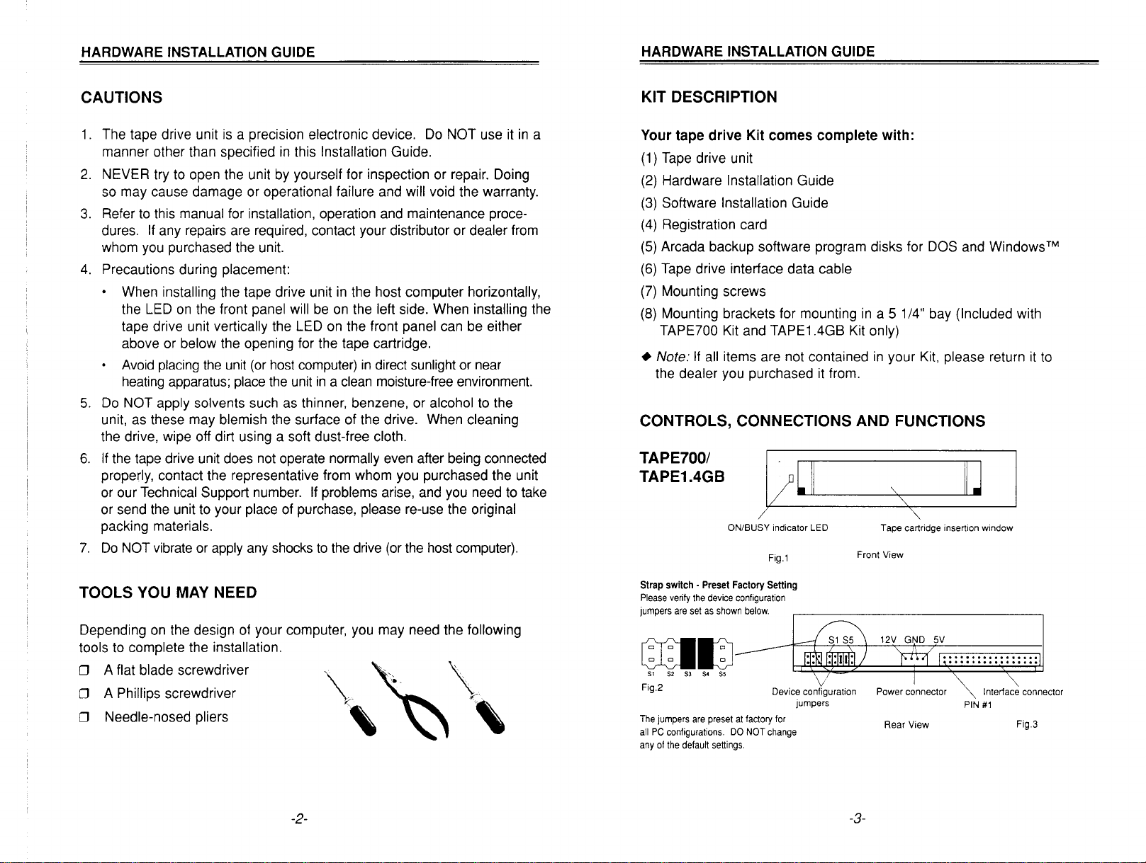
CONTROLS, CONNECTIONS AND FUNCTIONS
TAPE700/
TAPE1.4GB
ON/BUSY indicator LED
Tape cartridge insertion window
"'"
Fig.l
Front View
TOOLS YOU
MAY
NEED
Depending on the design of your computer, you may need the following
tools
to
complete the installation.
o A flat blade screwdriver
o A Phillips screwdriver
o Needle-nosed pliers
-2-
Strap
switch -
Preset
Factory
Please verify
jumpers
are
the
device configuration
set
as
shown
Setting
below.
~~
~~
51
52 53
54 55
Fig.2 Device configuration
The
jumpers
are
preset
at
all
PC
configurations.
any
of
the default settings.
factory for
DO
NOT change
jumpers
Power connector
Rear View Fig.3
-3-
Interface connector
PIN
#1
Page 4

HARDWARE INSTALLATION GUIDE
HARDWARE INSTALLATION GUIDE
CONTROLS, CONNECTIONS AND FUNCTIONS
COMB0700
Floppy ON/BUSY
ON/BUSY
Tape
indicator LED
indicator LED
Fig.4
Floppy eject button insertion window
Tape cartridge insertion window
Front View
~
~
Fig.S
,-
power connector
\
t2V
(continued)
Floppy disk
BEFORE YOU START
System Requirements
•
IBM
or
IBM-compatible personal computer,
• One available 31/2", (TAPE700
(TAPE700, TAPE1.4GB
or
OR
COMB0700).
• Caution: The tape drive interface data cable provided
in
IBM
PC/AT or 100% IBM-compatible
If
you
will
be
installing
you
will need the following:
the
Arcada backup software through
DOS: 386 or higher processor, 500
free disk space,
Windows: 386 or higher processor, 4
disk space, Windows
DOS
3.1
3.1
or
MB
or
higher.
higher.
386
or higher processor.
TAPE1.4GB) bay
PCs
only.
KB
RAM
minimum, 1.7
RAM
minimum, 1.7
or
51/4"
bay
can
be
used
WindowsTM,
MB
MB
free
NETWORK OPERATION
The tape drive of your Comb0700, TAPE700 or TAPE1.4GB will backup
and
restore files
network drives when running under NetWare ® (Versions 2.x
LANtastic™
server
can
on
and
Banyan Vines
easily
be
network drives
TM.
included
in
regular backups.
and
will restore files
Important files stored
on
local
on
a network
and
and
3.x),
Tape device
configuration jumpers
Fig.6
Tape Device
Please verify the device configuration jumpers are
as
set
jumpers
rations.
Configuration
shown
in
Fig. 2 on
are
preset at the factory for
DO
NOT change any of the default settings.
Jumpers
the previous page. The
all
PC
configu·
Tape power connector Tape interface connector
PIN#1
Rear
View
Floppy
Configuration
Please verify the device configuration jumpers
are set as shown
preset at the factory for
DO
NOT change any of the default settings.
in
Jumpers
Fig.
all
5.
PC
The jumpers are
configurations.
-4-
-5-
Page 5

HARDWARE INSTALLATION GUIDE
HARDWARE INSTALLATION GUIDE
HARDWARE INSTALLATION
Select a free drive bay and remove its cover plate OR remove
floppy drive
1.
Turn off your computer, monitor and any other peripherals.
2.
Unplug your computer, monitor and any other peripherals.
3.
Unscrew and remove the cover from the computer.
4.
Remove the cover plate from the free bay OR remove
so
you can install the tape drive unit
in
its place.
floppy drive.
5.
Currently, your floppy drives are connected to your floppy controller
board with an existing cable as shown below:
Fig.S
an
existing
an
existing
HARDWARE INSTALLATION (continued)
installing your tape drive unit, you will connect the tape drive
When
interface data
cable
as
shown
in
the appropriate figure below.
TAPE700ITAPE1.4GB
COMB0700
Floppy Controller
"
Tape drive interface
data
cable
Existing floppy
data cable
PIN 1
Fig.?
Connector for
drive
end)
A:
Existing floppy
data
Connector for
floppy drive
B:
-6-
cable
Connector for
floppy drive
(twisted end)
A:
Tape drive interface
data
cable
Existing floppy
data cable
COMB0700
Fig.S
-7-
Page 6

HARDWARE INSTALLATION GUIDE
HARDWARE INSTALLATION GUIDE
HARDWARE INSTALLATION
6.
Plug the tape drive interface data cable into the back of the tape
as
drive
7.
Route the tape drive interface data cable through the drive bay
opening and slide the tape drive unit into the drive
S.
Follow the flat ribbon cable from the back of the existing floppy
drive
color stripe, indicating
from the floppy controller.
9.
Match the color stripes
data cable into the second connector
data cable.
O.Plug
1
the
11
. Find any unused power cable inside your computer and plug it into
the back of the tape drive unit. The
power adapter. The power connector is keyed so that you can
only plug it
into place.
12.
Secure and ground the tape drive unit
• Note:
install the
13.
If
back on your computer. For the
on
shown.
to
the floppy controller. Make a note of the orientation of the
Pin 1 on the cable, then unplug this cable
on
the two cables, then plug your floppy drive
on
the tape drive interface
the remaining end of the tape drive interface data cable
floppy controller card. Orient the color stripe as noted
COMB0700 comes with a dual
in
one way. Press firmly until the connector snaps
in
the
bay,
You
do not need to change your CMOS settings when you
TAPE700 or TAPE1.4GB.
you are installing the TAPE700 or TAPE 1.4GB, put the cover
COMB0700 installation, continue
to
the next section.
(continued)
bay.
into
in
Step
if necessary.
S.
CONFIGURING THE FLOPPY DRIVE FOR COMB0700 (cont'd)
2.
To
configure
COMB0700
Connector
shown
3.
Connect the ground cable if your system requires
• Note:
install the
1.44MB floppy drive type.
You
MUST change your CMOS settings if the built-in floppy drive
different than the drive you removed. Consult your computer system
manual for how to change the
as
your
B:
drive, connect the built-in floppy drive of your
to
Connector
B:
is
the middle connector of the existing floppy data cable
in
Figure
S.
You
DO NOT need to change your CMOS settings when you
COMB0700, IF the floppy drive you have removed
B:
on
the existing floppy data cable.
CMOS settings.
it.
is
a
is
TAPE LOADING AND EJECTION
Tape Loading
1.
Hold the tape with the label facing upward and the tape window
facing the drive.
2.
Insert the tape into the tape drive slot keeping the tape
as possible while pushing the center of the tape until the tape cart-
ridge snaps and locks into place. When fully inserted, the tape
0.5"
cartridge extends approximately
Tape Ejection
1.
Hold tape and firmly remove it straight out from drive.
out.
as
straight
as
CONFIGURING THE FLOPPY DRIVE FOR COMB0700
1.
To
configure the floppy drive of the COMB0700 unit as your A drive,
A:
connect the built-in floppy drive to Connector
A:
drive data cable. Connector
as
shown
floppy drive
in
Figure
in
your system.
6.
Connector
is the end connector of that cable
A:
must be used if this is the only
-8-
on the existing floppy
• Caution:
causing damage:
2.
After ejection, store the tape
tape carrying case until it is to
be used again.
To
prevent the tape from becoming excessively loose and
DO NOT eject a tape while it
and the LED
DO
NOT switch the power off
while a tape
is
on.
is
running.
in
is
a
-9-
running
Insert this edge into tape drive
Write protection tab
Y
Tape
window
Page 7

HARDWARE INSTALLATION GUIDE
HARDWARE INSTALLATION GUIDE
SPECIFICATIONS
~
o
o
,....
W
0-
«
...
~
o
o
,....
o
In
::iE
o
C,.)
t::
::.:::
23
C\J
o
(')
~
LL
l-
s;:::
23
o
r"-
23
,....
o
(')
u..
LL
en
L{)
x
x
x
x
x
x
(f)
c
o
'iii
c
Ql
E
(5
>.
0.
0.
o
u:::
Ql
U
co
1::
Ql
C
Ql
>
.~
Z E
CD
~u
Oeo
00
r"-'<I:
Ql
>
~
Z E
eo
~U
oeo
LO~
(')0
"0
Ql
(f)
~
a.
0
"0
Ql
(f)
~
a.
0
o
r"-
(f)
0.
.D
~
CD
(jj
c
co
~-o
co
Ql
- Ql
COo.
DC/)
u
~
6
C\J
o
(')
o
a
co
E
o
LL
Ql
0.
co
I-
o
o
to
o
a
o
~
o
a
"0
co
Ql
.•
a:~
"0:=
~.D
co:;::;
~
11
3:
E
o 0
OU
LL
eo
l-
~
~
c:
o
o
o
,....
o
In
::iE
o
£
CII
>
";:
c
>-
c.
c.
o
u::
(f)
co
E
0
LL
>.
0.
0.
0
u:::
eo
::?
~
'<I:
,....
"0
c
co
eo
::.:::
0
C\J
,....
(f)
t::
0
0.
0.
::J
C/)
co
E
0
LL
..:.::
(f)
(5
eo
~
~
'<I:
,....
-
lo
('j
&
~
Ql
>
·c
0
C/)
0
~
u
RECOMMENDED TAPE MEDIA
For TAPE70Q &
Manufacturer
TEAC
3M
Verbatim
Gigatek
COMB0700
Capacity:
Formatted
QIC-3010
MC-3000XL
MC-3000XL
QIC-3010
MC-3000XL
MC
400'
Long
Up
to
680MB
MC
PIMAT
Format
Formatted
tape drives.
Max.
Compressed
Unformatted
MC-3000XL
MC-3000XL
MC-3000XL
295'
Up
Formatted
MC-3000
MC-3000
QIC-3010
Long
to
PIMAT
MC
-
Max.
500MB
Format
Capacity:
Compressed
Unformatted
Me-3DDD
MC-3000
-
For TAPE1.4GB tape drive.
400'
Long
Manufacturer
TEAC
3M
Gigatek
Capacity:
MC-3000XL
MC-3000XL
Up
to
1.4GB
.Formatted
QIC-3020
Max.
Compressed
MC
TAUMAT
QIC-3020
TECHNICAL SUPPORT
Refer to the Software Users Guide for technical support telephone number.
All
names indicated by ® and ™ are registered trademarks
USA. Features and specifications subject to change without notice. Manufacturer reserves the right to
substitute
manuals and accessories based upon availability. ® 1995 TEAC Corporation.
of
their respective companies. Printed
in
the
-10-
-11-
 Loading...