

Page 1

OPERATOR’S
MANUAL
Model C791 & C794
Soft Serve Freezer
Original Service Instructions
087482-M
3/5/2018 (Original Publication)
(Updated 5/13/19)
Page 2

Complete this page for quick reference when service is required:
Taylor Distributor:__________________________________________________________
Address:_________________________________________________________________
Phone: __________________________________________________________________
Service: _________________________________________________________________
Parts: ___________________________________________________________________
Date of Installation: ________________________________________________________
Information found on the data label:
Model Number: ___________________________________________________________
Serial Number:____________________________________________________________
Electrical Specs: Voltage__________________ Cycle__________
Phase__________________________________
Maximum Fuse Size: ______________________________________________________ A
Minimum Wire Ampacity:___________________________________________________ A
Note: Continuing research results in steady improvements; therefore, information in this manual is subject to change
without notice.
Note: Only instructions originating from the factory or its authorized translation representative(s) are considered to be
the original set of instructions.
© 2018 Taylor Company
087482-M
Any unauthorized reproduction, disclosure, or distribution of copies by an y pe rson of any portion of this work may be
a violation of copyright law of the United States of America and other countries, could result in the awarding of
statutory damages of up to $250,000 (17 USC 504) for infringement, and may result in further civil and criminal
penalties. All rights reserved.
Taylor Company
750 N. Blackhawk Blvd.
Rockton, IL 61072
Page 3

Section 1: To the Installer
Installer Safety....................................................................................................1-1
Site Preparation..................................................................................................1-1
Air-Cooled Units.................................................................................................1-1
Water Connections.............................................................................................1-2
Electrical Connections........................................................................................1-2
Electrical Hookup Installation.............................................................................1-3
Beater Rotation ..................................................................................................1-3
Refrigerant..........................................................................................................1-3
Section 2: To the Operator
Operator Information..........................................................................................2-1
Section 3: Safety
Installer Information............................................................................................3-1
Section 4: Operator Parts Identification
Model C791........................................................................................................4-1
Model C794........................................................................................................4-3
Beater Door Assembly .......................................................................................4-5
C791 and C794 Accessories..............................................................................4-6
Section 5: User Interface
Model C791 and Model C794.............................................................................5-1
Symbol Definitions..............................................................................................5-2
Power Switch......................................................................................................5-2
MIX REF Key......................................................................................................5-2
STANDBY Key...................................................................................................5-2
WASH Key .........................................................................................................5-3
AUTO Key..........................................................................................................5-3
Indicator Light—MIX LOW..................................................................................5-3
Indicator Light—MIX OUT..................................................................................5-3
RESET Button....................................................................................................5-3
Feed Tube..........................................................................................................5-4
Adjustable Draw Handle.....................................................................................5-4
Section 6: Operating Procedures
Assembly............................................................................................................6-1
Sanitizing............................................................................................................6-6
Priming...............................................................................................................6-8
Closing Procedure..............................................................................................6-9
Draining Product from the Freezing Cylinder.....................................................6-9
Rinsing ...............................................................................................................6-9
Cleaning...........................................................................................................6-10
i 087482-M
Page 4

Disassembly.....................................................................................................6-10
Brush Cleaning.................................................................................................6-10
Section 7: Operator’s Checklist
During Cleaning and Sanitizing..........................................................................7-1
Troubleshooting Bacterial Count........................................................................7-1
Regular Maintenance Checks............................................................................7-1
Winter Storage...................................................................................................7-2
Section 8: Troubleshooting Guide
Section 9: Parts Replacement Schedule
Maintenance Intervals........................................................................................9-1
Section 10: Limited Warranty on Equipment
Section 11: Limited Warranty on Parts
087482-M ii
Page 5

Section 1
!
!
The following information has been included in the
manual as safety and regulatory guidelines. For complete
installation instructions, please see the Installation
Checklist.
To the Installer
WARNING! This machine has many sharp
edges that can cause severe injuries.
Installer Safety
IMPORTANT! In all areas of the world,
equipment should be installed in accordance with
existing local codes. Pl ease contact your local authorities
if you have any questions.
Care should be taken to ensure that all basic safety
practices are followed during the installation and
servicing activities related to the installation and service
of Taylor
®
equipment.
• Only authorized Taylor service personnel should
perform installation, maintenance, and repairs
on Taylor equipment.
• Authorized service personnel should consult
OSHA Standard 29CFRI910.147 or the
applicable code of the local area for the industry
standards on lockout/tagout procedures before
beginning any installation or repairs.
• Authorized service personnel must ensure that
the proper protective equipment (PPE) is
available and worn when required during
installation and service.
• Authorized service personnel must remove all
metal jewelry, rings, and watches before
working on electrical equipment.
Site Preparation
Review the area where the unit will be installed before
uncrating the unit. Make sure that all possible hazards to
the user and the equipment have been addressed.
WARNING! Only install this machine in a
location where its use and maintenance is restricted to
trained personnel. Failure to comply may result in
personal injury.
For Indoor Use Only: This unit is designed to operate
indoors under normal ambient temperatures of
70°F to 75°F (21°C to 24C). The freezer has
successfully performed in high ambient temperatures of
104°F (40°C) at reduced capacities.
CAUTION! This machine must be installed on
a level surface to avoid the hazard of tipping. Extreme
care should be taken in moving this equipment for any
reason. Two or more persons are required to safely move
this machine. Failure to comply may result in personal
injury or equipment damage.
Uncrate the machine and inspect it for damage. Report
any damage to your Taylor distributor.
1
DANGER! The main power supply(s) to the
machine must be disconnected prior to performing any
installation, maintenance, or repairs. Failure to follow this
instruction may result in personal injury or death from
electrical shock or hazardous moving parts as well as
poor performance or damage to the machine.
Note: All repairs must be performed by a Taylor service
technician.
To the Installer
This piece of equipment is made in the USA and has
USA sizes of hardware. All metric conversions are
approximate and vary in size.
Air-Cooled Units
Do not obstruct air intake and discharge openings.
These units require 3 in. (76 mm) of space on all sides.
Install the deflector provided to prevent recirculation of
warm air. Minimum air clearances must be met to ensure
adequate air flow for optimum performance.
087482-M
1-1
Page 6

TO THE INSTALLER
!
FOLLOW YOUR LOCAL ELECTRICAL CODES.
Water Connections
Water-Cooled Units Only: An adequate cold water
supply must be provided with a hand shutoff valve. On
the underside rear of the base pan, two 3/8 in. I.P.S.
water connections for inlet and outlet have been provided
for easy hookup. Water lines connected to the machine
should have 1/2 in. inside diameters. (Flexible lines are
1
recommended, if local codes permit.) Depending on local
water conditions, it may be advisable to install a water
strainer to prevent foreign substances from clogging the
automatic water valve. There will be only one water-in
and one water-out connection. Do not install a hand
shutoff valve on the water-out line! Water should always
flow in this order: first, through the automatic water valve;
second, through the condenser; and third, through the
outlet fitting to an open trap drain.
CAUTION! A backflow prevention device is
required on the incoming water connection side on this
machine. Please refer to the applicable national state
and local codes for determining the proper configuration.
Failure to adhere to this safety precaution may result in
personal injury.
Electrical Connections
Each unit requires one power supply for each data label
on the unit. Check the data label(s) on the freezer for
branch circuit overcurrent protection or fuse, circuit
ampacity, and other electrical specifications. See the
wiring diagram provided inside the electrical box for
proper power connections.
In the United States, this equipment is intended to be
installed in accordance with the National Electrical Code
(NEC) ANSI/NFPA 70-1987. The purpose of the NEC
code is the practical safeguarding of persons and
property from hazards arising from the use of electricity.
This code contains provisions considered necessary for
safety. Compliance therewith and proper maintenance
will result in an installation essentially free from hazard!
In all other areas of the world, equipment should be
installed in accordance with the existing local codes.
Please contact your local authorities.
IMPORTANT! An equipotential grounding lug is
provided with this machine. Some countries require the
grounding lug to be properly attached to the rear of the
frame by the authorized installer. The installation location
is marked by the equipotential bonding symbol (5021 of
IEC 60417-1) on both the removable panel and the
machine's frame.
IMPORTANT!
• Stationary appliances which are not equipped
with a power cord and a plug or another device
to disconnect the appliance from the power
source must have an all-pole disconnecting
device with a contact gap of at least 0.125 in. (3
mm) installed in the external installation.
• Appliances that are permanently connected to
fixed wiring and for which leakage currents may
exceed 10 mA, particularly when disconnected
or not used for long periods, or during initial
installation, shall have protective devices to
protect against the leakage of current, such as a
GFI, installed by the authorized personnel to the
local codes.
• Supply cords used with this machine shall be
oil-resistant, sheathed flexible cable not lighter
than ordinary polychloroprene or other
equivalent synthetic elastomer-sheathed cord
(code designation 60245 IEC 57) installed with
the proper cord anchorage to relieve conductors
from strain, including twisting, at the terminals
and protect the insulation of the conductors from
abrasion.
• If the supply cord is damaged, it must be
replaced by an authorized Taylor service
technician in order to avoid a hazard.
1-2
087482-M
To the Installer
Page 7
Electrical Hookup Installation
!
!
(60 Cycle, 1 Ph, Supplied with Cord and Plug)
This freezer is supplied with a three-wire cord and
grounding plug for connection to a single-phase, 60cycle, branch circuit supply. This unit must be plugged
into a properly grounded receptac le. For ex am p le, the
cord and plug provided for 115/60/1 is 20 A; therefore,
the wall outlet must also be 20 A. Check the data label,
located on the side panel, for electrical specifications.
Permanent wiring may be employed if required by local
codes. Instructions for conversion to permanent wiring
are as follows:
• Be sure the freezer is electrically disconnected.
• Remove the appropriate panel and locate the
small electrical box at the base of the freezer.
• Remove the factory-installed cord and strain
relief bushing.
• Route incoming permanent wiring through 7/8
in. (22 mm) hole in base pan.
• Connect two power supply leads. Attach ground
(earth) wire to the grounding lug inside the
electrical box.
• Be sure the unit is properly grounded before
applying power.
TO THE INSTALLER
CAUTION! Use only R404A refrigerant that
conforms to the AHRI standard 700 specification. The
use of any other refrigerant may expose users and
operators to unexpected safety hazards.
WARNING! Refrigerant liquid sprayed onto the
skin may cause serious damage to tissue. Keep eyes
and skin protected. If refrigerant burns should occur,
flush immediately with cold water. If burns are severe,
apply ice packs and contact a physician immediately.
NOTICE! Taylor reminds technicians to be
aware of and in compliance with local government laws
regarding refrigerant recovery, recycling, and reclaiming
systems. For information regarding applicable local laws,
please contact your local authorized Taylor distributor.
1
Beater Rotation
NOTICE! Beater rotation must be clockwise as
viewed looking into the freezing cylinder.
Refrigerant
CAUTION! In consideration of our environment,
Taylor uses only earth-friendly HFC refrigerants. The
HFC refrigerant used in this unit is R404A. This
refrigerant is generally considered nontoxic and
nonflammable, with an ozone depleting potential (ODP)
of zero (0). However, any gas under pressure is
potentially hazardous and must be handled with caution.
NEVER fill any refrigerant cylinder completely with liquid.
Filling the cylinder to approximately 80% will allow for
normal expansion.
IMPORTANT! R404A refrigerant used in
conjunction with polyolester oils is extremely moisture
absorbent. When opening a refrigeration system, the
maximum time the system is open must not exceed 15
minutes. Cap all open tubing to prevent humid ai r or
water from being absorbed by the oil.
To the Installer
087482-M
1-3
Page 8

TO THE INSTALLER
1
1-4
087482-M
To the Installer
Page 9
Section 2
Operator Information
This soft serve freezer has been carefully engineered
and manufactured to give you dependable operation.
This machine, when properly operated and cared for, will
produce a consistent quality product. Like all mechanical
products, it will require cleaning and maintenance. A
minimum amount of care and attention is necessary if the
operating procedures outlined in this manual are followed
closely.
To the Operator
IMPORTANT! If the crossed-out, wheeled-bin
symbol is affixed to this machine, it signifies that this
machine is compliant with the EU Directives as well as
other similar end-of-life legislation in effect after August
13, 2005. Therefore, it must be collected separ ately after
its use is completed and cannot be disposed as unsorted
municipal waste.
2
The Taylor soft serve models covered in this manual are
C791 and C794.
IMPORTANT! This manual should be read
before operating or performing any maintenance on the
machine.
Your Taylor machine will NOT compensate for and/or
correct any errors made during the setup or filling
operations. Thus, the initial assembly, setup, and priming
procedures are of extreme importance. It is strongly
recommended that all personnel responsible for the
machine’s operation, including assembly and
disassembly, go through these procedures together in
order to be properly trained and to make sure that all
personnel understand their role in using and maintaining
the machine.
In the event you should require technical assistance,
please contact your local authorized Taylor distributor.
The user is responsible for returning the machine to the
appropriate collection facility, as specified by your local
code.
For additional information regarding applicable local
disposal laws, please contact the municipal waste facility
and/or local authorized Taylor distributor.
Note: Your Taylor warranty is valid only if the parts are
authorized Taylor parts purchased from the local
authorized Taylor distributor, and only if all required
service work is provided by a Taylor service technician.
Taylor reserves the right to deny warranty claims on units
or parts if unapproved parts or incorrect refrigerant were
installed in the unit, system modifications were performed
beyond factory recommendations, or it is determined that
the failure was caused by abuse, misuse, neglect, or
failure to follow all operating instructions. For full details
of your Taylor warranty, please see
Equipment" on page 10-1 and "Limited Warranty on
Parts" on page 11-1.
To the Operator
"Limited Warranty on
087482-M
2-1
Page 10

TO THE OPERATOR
Compressor Warranty Disclaimer
The refrigeration compressor(s) on this unit are
warranted for the term stated in the Limited Warr an ty
section in this manual. However, due to the Montreal
Protocol and the U.S. Clean Air Act Amendments of
1990, many new refrigerants are being tested and
developed, thus seeking their way into the service
industry. Some of these new refrigerants are being
advertised as drop-in replacements for numerous
applications. It should be noted that in the event of
ordinary service to this unit's refrigeration system, only
2
the refrigerant specified on the affixed data label
should be used. The unauthorized use of alternate
refrigerants will void your Taylor compressor warranty. It
is the unit owner's responsibility to make this fact known
to any technician he employs.
It should also be noted that Taylor does not warrant the
refrigerant used in its equipment. For example, if the
refrigerant is lost during the course of ordinary service to
this machine, Taylor has no obligation to either supply or
provide its replacement either at billable or non-billable
terms. Taylor does have the obligation to recommend a
suitable replacement if the original refrigerant is banned,
obsoleted, or no longer available during the five-year
warranty of the compressor.
The Taylor Company will continue to monitor the industry
and test new alternates as they are being develop e d.
Should a new alternate prove through our testing that it
would be accepted as a drop-in replacement, the above
disclaimer would become null and void. To find the
current status of an alternate refrigerant as it relates to
your compressor warranty, call the local Taylor distr ibutor
or the Taylor factory. Be prepared to provide the model/
serial number of the unit in question.
2-2
087482-M
To the Operator
Page 11
Section 3
!
Installer Information
We at the Taylor Company are concerned about the
safety of the operator when he or she comes into co ntact
with the freezer and its parts. Taylor has gone to extr eme
efforts to design and manufacture built-in safety features
to protect both you and the service technician. As an
example, warning labels have been attached to the
freezer to further point out safety precautions to the
operator.
Safety
WARNING! This unit has many sharp edges
that can cause severe injuries.
• DO NOT put objects or fingers in the door
spout. This may contaminate the product and
cause severe personal injury from blade
contact.
• USE EXTREME CAUTION when removing the
beater assembly. The scraper blades are very
sharp.
DANGER! Failure to adhere to the following
safety precautions may result in severe personal injury or
death. Failure to comply with these warnings may also
damage the unit and/or its components. Such damage
may result in component replacement and se rvice repair
expenses.
To Operate Safely
NOTICE! DO NOT operate the unit without
reading this entire manual first. Failure to follow all of
these operating instructions may result in dam ag e to the
unit, poor performance, health hazards, or personal
injury.
WARNING! Avoid injury.
• DO NOT allow untrained personnel to operate
this unit.
• DO NOT operate the unit unless all service
panels and access doors are restrained with
screws.
• DO NOT remove any internal operating parts
(including, but not limited to, freezer door,
beater, or scraper blades), unless all control
switches are in the OFF position.
Failure to follow these instructions may result in severe
personal injury, especially to fingers or hands, from
hazardous moving parts.
!
IMPORTANT! Access to the service a rea of the
unit is restricted to persons having knowledge and
practical experience with the appliance, in particular as
far as safety and hygiene are concerned.
CAUTION! This machine must be placed on a
level surface. Extreme care should be taken when
moving for any reason. Two or more pe rs on s ar e
required to safely move this machine. Failure to comply
may result in personal injury or damage to the machine.
WARNING! Avoid injury.
• DO NOT operate this machine unless it is
properly grounded.
• DO NOT operate this machine with larger fuses
than specified on the unit's data label.
• All repairs should be performed by an
authorized Taylor service technician.
• Cord-Connected Units: Only authorized Taylor
service technicians may install a plug on this
unit.
• The main power supplied to the machine must
be disconnected prior to performing installation,
repairs, or maintenance.
3
Safety
087482-M
3-1
Page 12

SAFETY
!
3
• Machines that are permanently connected to
fixed wiring and for which leakage currents may
exceed 10 mA, particularly when disconnected
or not used for long periods, or during initial
installation, shall have protective devices to
protect against the leakage of current, such as a
GFI, installed by the authorized personnel to the
local codes.
• Stationary machines which are not equipped
with a power cord and a plug or another device
to disconnect the appliance from the power
source must have an all-pole disconnecting
device with a contact gap of at least 0.125 in. (3
mm) installed in the external installation.
• Supply cords used with this unit shall be
oil-resistant, sheathed flexible cable not lighter
than ordinary polychloroprene or other
equivalent synthetic elastomer-sheathed cord
(code designation 60245 IEC 57) installed with
the proper cord anchorage to relieve conductors
from strain, including twisting, at the terminals
and protect the insulation of the conductors from
abrasion.
• If the supply cord is damaged, it must be
replaced by an authorized Taylor service
technician in order to avoid a hazard.
performed in high ambient temperatures of up to 104°F
(40°C) at reduced capacities.
Noise Level: Airborne noise emission does not exceed
78 dB(A) when measured at a distance of 39 in. (1.0 m)
from the surface of the unit and at a height of 62 in.
(1.6 m) from the floor.
Failure to follow these instructions may result in
electrocution. Contact your local authorized Taylor
distributor for service.
CAUTION! This unit is equipped with a
refrigerated cabinet, designed to maintain product
temperature at or below 41°F (5°C). Any product being
added to this machine must be below 41°F (5°C). Failure
to follow this instruction may result in health hazards and
poor freezer performance.
DO NOT run the unit without product. Failure to follow
this instruction can result in damage to the unit.
DO NOT obstruct air intake and discharge openings.
These units require 3 in. (76 mm) of space on all sides.
Install the deflector provided to prevent recirculation of
warm air. Failure to follow this instruction may cause poor
freezer performance and damage to the machine.
For Indoor Use Only: This unit is designed to operate
indoors, under normal ambient temperatures of 70°F to
75°F (21°C to 24°C). The unit has successfully
3-2
087482-M
Safety
Page 13
Section 4
1
5
7
8
14
3
4
6
9
12
11
10
13
16
15
2
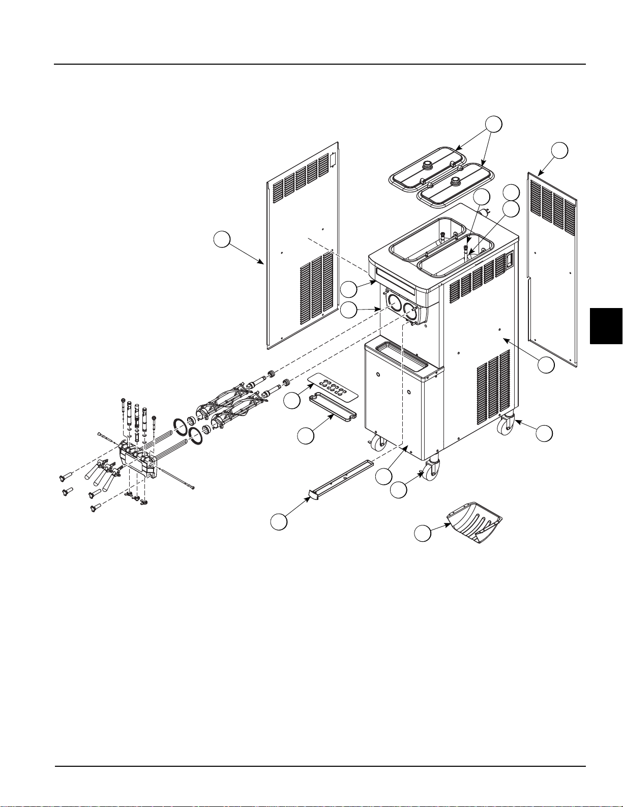
Model C791
Operator Parts Identification
4
Figure 4-1
Operator Parts Identification
087482-M
4-1
Page 14

OPERATOR PARTS IDENTIFICATION
Item Description Part No.
1 Panel-Side-Left 085549
2 Cover-Hopper-14 QT-Black 041682-BLA
3 Orifice 022465- 100
4 Tube-Feed X29429-2
5 O-ring-.643 OD X .077W 018572
6 Panel-Rear-Air Cooled 086838
7 Panel-Side-Right 085548
8 Caster-4"-SWV-5/8 Stem X 1-3/8 018794
4
Item Description Part No.
9 Deflector 084447
10 Caster-4"-SWV-5/8 Stem X 1-3/8 034081
11 Panel A.-Front-Lower X86614 -SER
12 Pan-Drip 19-1/2 Long 085296
13 Tray-Drip 085699-1
14 Shield-Splash 086854
15 Panel-Front 086615
16 Plate-Dec X85804
4-2
087482-M
Operator Parts Identification
Page 15

Model C794
1
5
7
8
14
3
4
6
9
12
11
10
13
16
15
2
OPERATOR PARTS IDENTIFICATION
4
Figure 4-2
Operator Parts Identification
087482-M
4-3
Page 16

OPERATOR PARTS IDENTIFICATION
Item Description Part No.
1 Panel-Side-Left 085549-SP1
2 Cover-Hopper-14 QT-Black 041682-BLA
3 Orifice 022465- 100
4 Tube-Feed X29429-2
5 O-ring-.643 OD X .077W 018572
6 Panel-Rear 086618
7 Panel-Side-Right 085548-SP1
8 Caster-4"-SWV-5/8 Stem X 1-3/8 018794
4
Item Description Part No.
9 Deflector 084447
10 Caster-4"-SWV-5/8 Stem X 1-3/8 034081
11 Panel A.-Front-Lower X86614 -SER
12 Pan-Drip 19-1/2 Long 085296
13 Tray-Drip 085699-1
14 Shield -Splash 086854
15 Panel-Front 086615
16 Stud-Nose Cone 022822
4-4
087482-M
Operator Parts Identification
Page 17

Beater Door Assembly
1
16
13
18
17
2
3
5
6
4
19a
7
9
10
8
19
20b
20
20a
11
12
15
30221_A
14
OPERATOR PARTS IDENTIFICATION
Item Description Part No.
1 Valve A.- Draw X69539-SP
2 Valve A.- Draw X84411-SP
3 O-ring-7/8 OD X .0103W-SIL 083693
4 Seal- Draw Valve 034698
5 Plug- Prime 028805-SP1
6 O-ring- 3/8 OD X .070W 016137
7 Gasket-Door HT 4 in. 048926
8 Bearing-Front 050216
Figure 4-3
Item Description Part No
13 Rod A.- Pivot X20683
14 O-ring 5/16 OD x .070 W 0162 72
15 Decal-Door-3 Spout-Twin Twi s 062239
16 Cap-Design 1.010"ID-6 PT. 014218
17 Nut-Stud-Black 2.563 Long 058764
18 Nut-Stud-Black 3.250 Long 058765
19 Door A.-3SPT*LGBAF*Black X49461-52S
19a Baffle A.-Long 4 in. X50882
4
9 Beater A.- Helicore X31761
10 Blade-Scraper 035174
11 Shaft-Beater 032564
12 Seal-Drive Shaft 032560
Operator Parts Identification
20 Handle A-Draw-Black X81010-SP1
20a Screw-Adjustmt-5/16-24 056332
20b O-ring-1/4 OD X .070W 50 015872
087482-M
4-5
Page 18

OPERATOR PARTS IDENTIFICATION
1
2
3
4
5
6
7
C791 and C794 Accessories
4
Item Description Part No
1 Pail-10 qt. 013163
2 Brush-Rear BRG 1 in. D X 2 in. LG 013071
3 Brush-Double Ended-Pump and
Feed
4 Brush-Draw·Valve·1” OD X 2” X
17”
5 Brush-Mix Pump Body-3”X7”
White
013072
013073
023316
Figure 4-4
*Not Shown: Stera Sheen® part no. 055492 (100 2 oz. packs)
Item Description Part No.
6 Lubricant-Taylor 4 oz. 047518
7 Kit A.-Tune Up-3 Spout-Non HT X49463-4
8* Deflector-Blower Exhaust 084447
9* Sanitizer-Stera Sheen-Green 055492
4-6
087482-M
Operator Parts Identification
Page 19

Section 5
1
5
3
2
3
4
5
4
7
6
6 7
8
Model C791 and Model C794
User Interface
Figure 5-1
Item Description
1 Power Switch
2MIX REF Key
3 STANDBY Key
4 WASH Key
RESET
Item Description
5AUTO Key
6 Indicator Light—Mix Low
7 Indicator Light—Mix Out
8 Reset Button
5
User Interface
087482-M
5-1
Page 20

USER INTERFACE
30122
Symbol Definitions
To better communicate in the international arena, the
words on many of our operator switches and keys have
symbols to indicate their functions. Your Taylor
equipment is designed with these international symbols.
The following chart identifies the symbol definitions used
on the operator switches.
O OFF WASH
ION AUTO
MIX MIX LOW
STANDBY MIX OUT
Power Switch
When placed in the ON position, the power switch allows
™
Softech
control panel operation.
5
1. Remove the air orifices and invert the mix feed tubes
so that the end with the mix delivery hole is
positioned at the top. Install the end without the mix
delivery hole into the mix inlet hole in the bottom of
the hopper. This will prevent mix from entering the
freezing cylinders.
MIX REF Key
When the MIX REF key is pressed, the light comes on,
indicating the mix hopper refrigeration system is
operating. Mix refrigeration is controlled by the left side of
the freezer as viewed from the operator end. The mix
refrigeration cannot be canceled unless the auto or
standby modes are canceled first.
STANDBY Key
This unit is equipped with a standby feature. If product is
not dispensed for long periods of time (example: early
morning hours), the standby feature can be activate d to
maintain the hopper and freezing cylinder pr oduct at safe
temperatures and prevent product breakdown. In the
standby mode, the wash and auto functions are
automatically canceled.
To use the standby feature, perform the following steps.
Note: Make sure your hands are clean and sanitized
before performing the following steps.
Figure 5-2
2. Make sure there are at least 3 in. (76 mm) of mix in
the hopper and that the level of mix is not above the
mix delivery hole on the side of the feed tubes.
Note: The level of mix must be below the mix delivery
hole on the side of the feed tube. Failure to follow this
instruction may result in lower product quality when
normal operation is resumed.
3. Press the STANDBY key. The light will illuminate,
indicating that the unit is operating as a refrigerator
for product in the hopper and freezing cylinder.
4. To remove the unit from the standby mode, press the
AUTO key. The STANDBY light will extinguish,
indicating the unit has resumed the normal operating
mode.
5-2
087482-M
User Interface
Page 21

USER INTERFACE
30123
5. When the unit cycles off, place the feed tubes in its
original position (mix delivery hole end down) and
install air orifices.
refilled as soon as possible. Always maintain at least 3 in.
(76 mm) of mix in the hopper. If you neglect to add mix, a
freeze-up may occur. This will cause eventual damage to
the beater, blades, drive shaft, and freezer door.
Indicator Light—MIX OUT
When the Mix Out symbol is illuminated, the mix hopper
has almost completely exhausted and has an insufficient
supply of mix to operate the freezer. At this time, the Auto
mode is locked out and the freezer will be placed in the
Standby mode. To initiate the refrigeration system, add
mix to the mix hopper and touch the Auto symbol. The
freezer will automatically begin operation.
RESET Button
The reset button is located on the front of the C791 and
C794. The reset protects the beater motor from an
overload condition. If an overload occurs, the reset
mechanism will trip. To properly reset the freezer:
1. Press the AUTO key to cancel the cycle.
Figure 5-3
Important! The standby mode must not be used instead
of daily disassembly, cleaning, and sanitizing.
WASH Key
When the WASH key is pressed, the light comes on,
indicating beater motor operation. The Standby or Auto
mode must be canceled first to activate the Wash mode.
AUTO Key
When the AUTO key is pressed, the light comes on,
indicating that the main refrigeration system has been
activated. In the Auto mode, the wash or standby
functions are automatically cance led . Th e mix
refrigeration function is automatically locked in to
maintain the temperature of the mix in the mix hopper.
Note: An indicating light and an audible tone will sound
whenever a mode of operation has been pressed. To
cancel any function, press the key again. The light and
mode of operation will shut off.
2. Turn the power switch to the OFF position.
5
CAUTION! DO NOT use metal objects to press
the reset button. Failure to follow this instruction may
result in electrocution.
3. Wait two or three minutes and then press the reset
button firmly.
4. Turn the power switch to the ON position.
5. Press the WASH key and observe the freezer's
performance. If the beater motor is turning properly,
press the WASH key to cancel the cycle.
6. Press the AUTO key on both sides of the unit to
resume normal operation. If the freezer shuts down
again, contact a Taylor service technician.
Indicator Light—MIX LOW
Located on the front of the machine is a mix level
indicating light. When the light is flashing, it indicates that
the mix hopper has a low supply of mix and should be
User Interface
087482-M
5-3
Page 22

USER INTERFACE
30124
30123
30121
Feed Tube
The feed tube maintains over-run and allows enough mix
to enter the freezing cylinder after a draw. One end of the
tube has a mix delivery hole on the side, and the other
end does not.
Figure 5-4
The feed tube serves two purposes.
• Normal Operation: After priming the machine, the
5
end of the feed tube with the mix delivery hole is
placed in the mix inlet hole, and the air orifice is
installed. Every time the draw handle is raised, new
mix and air from the hopper will flow down into the
freezing cylinder. This will keep the freezing cylinder
properly loaded and will maintain overrun.
• Standby Operation: During long “no sale” periods,
the air orifice is removed and the feed tube is
inverted. The end of the feed tube without the mix
delivery hole is placed in the mix inlet hole to prevent
mix from entering the freezing cylinder.
Figure 5-6
Note: Make sure the level of mix is below the mix
delivery hole in the side of the feed tube. Failure to follow
this instruction may result in lower product quality when
normal operation is resumed.
Figure 5-5
Adjustable Draw Handle
These units feature an adjustable draw handle to provide
the best portion control, giving a better, consistent quality
to your product and controlling costs. The draw handle
should be adjusted to provide a flow rate of 5 oz. to
7-1/2 oz. (142 g to 213 g) of product by weight per 10
seconds. To increase the flow rate, tighten the screw. To
decrease the flow rate, loosen the screw.
Important! When dispensing product, pull only one draw
handle at a time.
Figure 5-7
5-4
087482-M
User Interface
Page 23

Section 6
11269
Operating Procedures
The Model C791 and C794 are console models with a
three-spout door. These models have a 3.4 qt. (3.2 L)
capacity freezing cylinder and 14 qt. (13.2 L) capacity mix
hoppers. The mix flows by gravity from the hopper to the
freezing cylinder through a feed tube.
We begin our instructions at the point where we enter th e
store in the morning and find the parts disassembled and
laid out to air dry from the previous night's cleaning.
These opening procedures will show you how to
assemble these parts into the machine, sanitize them,
and prime the machine with fresh mix in prepara tio n to
serve your first portion.
Duplicate the procedures where they apply for the
second freezing cylinder.
If you are disassembling the machine for the first time or
need information to get to the starting point in our
instructions, turn to
start there.
"Disassembly" on page 6-10, and
Assembly
Note: When lubricating parts, use an approved food
grade lubricant (example: Taylor Lube).
WARNING! Make sure the power switch is in
the OFF position. Failure to follow this instruction may
result in severe personal injury from hazardous moving
parts.
1. Lubricate the groove and shaft portion that comes in
contact with the bearing on the beater drive shaft.
Slide the seal over the shaft and groove until it snaps
into place. Do not lubricate the hex end of the drive
shaft. Fill the inside portion of the seal with 1/4 in.
more lubricant and lubricate the flat side of the seal
that fits onto the rear shell bearing.
6
Figure 6-1
2. Repeat step 1 for the other drive shaft(s).
Operating Procedures
087482-M
6-1
Page 24

OPERATING PROCEDURES
30131_A
11097
3. Insert the drive shafts into the freezing cylinders, hex
end first, and into the rear shell bearings until the
seals fit securely over the rear shell bearings.
Engage the hex ends firmly into the drive couplings.
Be sure the drive shafts fit into the drive couplings
without binding.
Figure 6-2
4. Take one of the scrape r bla des an d slip it under th e
hook at the front of the beater. Wrap the blade
around the beater, following the helix and pushing the
blade down onto the helix as you wrap. At the back
end of the beater, slip the blade under the hook.
8. Slide the beaters the remainder of the way into the
freezing cylinders and over the end of the drive
shafts. The beaters should fit tightly, but not so tightly
that the beaters cannot be turned slightly to engage
the drive shafts. If the beaters slide in too easily with
little or no resistance, there will not be enough force
against the beaters to hold the blades in place. If this
is the case, contact your authorized Taylor service
technician.
Figure 6-4
Note: Do not lubricate the gasket(s) or the front
bearing(s).
6
Figure 6-3
5. Repeat step 4 for the second scraper blade.
6. Repeat step 4 and step 5 for the other beater.
7. Holding the beater(s) securely, slide the beaters
one-third of the way into the freezing cylinders.
Looking into the freezing cylinders, align the hole at
the rear of the beaters with the flats on the end of the
drive shafts.
9. Place the large rubber gaskets into the grooves on
the back side of the freezer door.
10. Slide the white plastic front bearings over the baffle
rods onto the bearing hubs, making certain that the
flanged end of the bearing is resting against the
freezer door.
Figure 6-5
11. Slide the two O-rings into the grooves on each prime
plug. Apply an even coat of Taylor Lube to the
O-rings and shafts.
6-2
087482-M
Operating Procedures
Page 25

Figure 6-6
11092
10518
10770
10519
10520
12. Insert the prime plugs into the holes in the top of the
freezer door and push down.
OPERATING PROCEDURES
Note: The short handscrews go on the bottom, and the
long handscrews go on the top.
14. With the door seated on the freezer studs, install the
handscrews. Tighten equally in a crisscross pattern
to ensure the door is secured.
Figure 6-9
15. Slide the two O-rings into the grooves of each
standard draw valve. Slide the H-ring and O-ring into
the grooves of the center draw valve. Lubricate the
H-ring and O-rings.
Figure 6-7
13. Insert the baffle rod(s) through the op e nin g in the
beater(s) and seat the door flush with the freezing
cylinder.
Figure 6-8
6
Figure 6-10
Operating Procedures
087482-M
6-3
Page 26

OPERATING PROCEDURES
30131_A
30223_A
30135_A
30224_A
16. Lubricate the inside of the freezer door spouts from
the bottom. Insert the draw valves into the freezer
door from the bottom until the slot in the draw valves
comes into view.
Figure 6-11
17. Slide the O-ring onto each pivot pin and lubricate.
18. These units have three draw handles. Slide the fork
of the draw handle in the slot of the draw valve,
starting from the right. Slide the pivot pin through
each draw handle as you insert them into the draw
valves.
Figure 6-13
Note: These units feature adjustable draw handles to
provide the best portion control. The draw handles can
be adjusted for different flow rates. See
"Adjustable Draw
Handle" on page 5-4 for more information on adjusting
these handles.
19. Snap the design caps over the bottom of the freezer
door spouts.
6
Figure 6-12
Figure 6-14
6-4
087482-M
Operating Procedures
Page 27

20. Install the front drip tray and the splash shield under
30220_A
30138_A
the door spout(s).
Figure 6-15
21. Slide the rear drip pan into the ho le in the fr ont pa nel.
OPERATING PROCEDURES
Figure 6-17
23. Slide the small O-ring into the groove of the air
orifice. Do not lubricate the O-ring.
Figure 6-16
22. Slide two O-rings on one end of the air tube. Slide
two O-rings on the other end of the air tube.
6
Figure 6-18
Note: Make sure the hole in the air orifice is clean and is
not clogged. If the hole in the air orifice should become
clogged, use soap and hot water to clear the hole. Do
not enlarge the hole in the air orifice.
Operating Procedures
087482-M
6-5
Page 28

OPERATING PROCEDURES
!
12029
30139_A
30140_A
30226_A
24. Install the air orifice into the hole in the top of the air
tube (in the end without the small hole on the side).
Figure 6-19
25. Lay the air tube (with the air orifice installed) in the
bottom of the mix hopper for sanitizing.
26. Repeat step 22 through step 25 for the other side of
the freezer.
3. While the solution is flowing into the freezing cylinder,
brush clean the mix hopper. When cleaning the
hopper, take particular care in brushing the mix level
sensing probe on the rear wall of the hopper, mix inlet
hole, and air tube.
Figure 6-21
CAUTION! DO NOT run the machine without
product. Failure to follow this instruction can result in
damage to the machine.
6
Sanitizing
1. Prepare an approved 100 PPM sanitizing solution
®
(examples: 2.5 gal. [9.5 L] of Kay-5
®
of Stera-Sheen
manufacturer's specifications.
2. Pour the sanitizing solution into the hopper and allow
it to flow into the freezing cylinder.
). Use warm water and follow the
or 2 gal. [7.6 L]
Figure 6-22
Figure 6-23
Figure 6-20
6-6
087482-M
Operating Procedures
Page 29

4. Place the power switch in the ON po sition .
13054w
30141_A
30142_A
Figure 6-24
5. Press the WASH key to cause the sanitizing solution
in the freezing cylinder to be agitated. Allow it to
agitate for five minutes.
OPERATING PROCEDURES
Figure 6-26
8. When a steady stream of sanitizing solution is flowing
from the prime plug opening in the bottom of the
freezer door, lower the draw handle. Draw off all the
sanitizing solution.
131558
Figure 6-25
6. Place an empty pail beneath the door spouts and
raise the prime plugs.
7. Momentarily pull the center draw handle down to
sanitize the center door spout.
6
Figure 6-27
9. Once the sanitizer stops flowing from the door spout,
raise the draw handle and press the WASH key,
canceling the beater motor operation.
Important! You have just sanitized the freezer. Be sure
your hands are sanitized before continuing these
instructions.
Operating Procedures
087482-M
6-7
Page 30

OPERATING PROCEDURES
30228_A
30142_A
30143_A
10. With sanitized hands, stand the feed tubes with air
orifices in the corner of the mix hopper.
Figure 6-28
11. Repeat step 1 through step 10 for the other side of
the freezer.
Figure 6-29
2. Once a steady stream of mix starts to flow from the
prime plug opening in the bottom of the fr eezer d oor,
push down the prime plug.
Priming
Prime the machine as close as possible to the time of first
product draw.
6
1. With a pail beneath the door spout, lower the draw
handle. Be sure the prime plug is still in the up
position. Pour 2 gal. (7.6 L) of fresh mix into the mix
hopper and allow it to flow into the freezing cylinder.
This will force out any remaining sanitizing solution.
When full-strength mix is flowing from the door spout,
raise the draw handle.
Note: Use only fresh mix when priming the freezing
cylinder.
Figure 6-30
6-8
087482-M
Operating Procedures
Page 31

OPERATING PROCEDURES
30227_A
!
ALWAYS FOLLOW LOCAL HEALTH CODES.
3. Lubricate the O-rings on the air tube on the end with
the small hole on the side.
4. Install the air tube (the end with the hole) with the air
orifice installed into the mix inlet hole in the mix
hopper.
5. Press the AUTO key. The AUTO light will come on,
indicating the main refrigeration system is operating.
When the unit cycles off, the product will be at
serving viscosity.
Draining Product from the Freezing Cylinder
1. Press the AUTO key to cancel operation. Press the
MIX REF key to cancel hopper refrigeration. These
operations should be canceled as far ahead of
cleaning time as possible to allow frozen product to
soften for easier cleaning.
Remove the mix hopper cover and feed tube from the
machine. Take them to the sink for cleaning.
2. If local health codes permit the use of rerun, place a
sanitized NSF-approved stainless steel rerun
container beneath the door spouts. Press the WASH
key and open the draw valves. When all the product
stops flowing from the door spouts, close the draw
valves and press the WASH key to cancel the wash
mode. Place the sanitized lid on the rerun container
and place it in the walk-in cooler.
Note: If local health codes do not permit the use of
rerun, the product must be discarded. Follow the
instructions in the previous step, except drain the product
into a pail and properly discard the mix.
Figure 6-31
Note: The MIX REF light will come on, indicating the mix
refrigeration system is operating to maintain the mix in
the mix hopper.
6. Fill the hopper with mix. As the mix level comes in
contact with the mix level sensing probe on the rear
wall of the hopper, the MIX LOW light will shut off.
7. Place the mix hopper cover in position over the mix
hopper.
8. Repeat step 1 through step 7 for the other side of the
freezer.
Closing Procedure
To disassemble these units, the following items will be
needed:
• Two cleaning pails
• Sanitized stainless steel rerun can with lid
• Necessary brushes (provided with machine)
• Cleaner
• Single-service towels
3. Repeat step 1 and 2 for the other side of the
machine.
Rinsing
Note: Do not brush clean the mix inlet hole while the
machine is in the WASH mode.
1. Pour 1 gal. (3.8 L) of cool, clean water into the mix
hopper. With the brushes provided, scrub the mix
hopper and the mix inlet hole.
2. With a pail beneath the door spout, raise the prime
plug and press the WASH key.
3. When a steady stream of rinse water is flowing from
the prime plug opening in the bottom of the freezer
door, open the draw valve. Drain all the rinse water
from the door spout. Close the draw valve, push the
prime plug down, and press the WASH key
cancelling the WASH mode.
Repeat this procedure until the rinse water being
drawn from the freezing cylinder is clear.
4. Repeat step 1 through step 3 for the other side of the
machine.
6
Operating Procedures
087482-M
6-9
Page 32

OPERATING PROCEDURES
Cleaning
1. Prepare an approved 100 PPM cleaning solution
®
(examples: 2.5 gal. [9.5 L] of Kay-5
®
of Stera-Sheen
manufacturer's specifications.
2. With the prime plug down, pour 1 gal. (3.8 L) of
cleaning solution into the mix hopper and allow it to
flow into the freezing cylinder.
3. While the solution is flowing into the freezing cylinder,
brush clean the mix hopper, the mix inlet hole, and
the mix level probe.
4. Press the WASH key to cause the cleaning solution
in the freezing cylinder to agitate.
5. Place an empty pail beneath the door spout and raise
the prime plug. When a steady stream of cleaning
solution is flowing from the prime plug opening in the
bottom of the freezer door, open the draw valve.
Draw off all of the solution.
6. Once the cleaning solution stops flowing from the
door spout, close the draw valve, push the prime plug
down, and press the WASH key cancelling the
WASH mode.
7. Repeat step 1 through step 6 for the other side of the
machine.
). Use warm water and follow the
or 2 gal. [7.6 L]
6
Disassembly
1. Remove the handscrews and the freezer door.
Remove beaters, scraper blades, and drive shafts
from the freezing cylinders. Take these parts to the
sink for cleaning.
2. Remove the front drip tray, splash shield, and drip
pans from the machine. Take them to the sink for
cleaning.
3. Remove the rear drip pan and take to the sink for
cleaning.
Brush Cleaning
1. Prepare a sink with an approved cleaning solution
®
(examples: Kay-5
water and follow the manufacturer's
specifications.
Important! Follow label directions. Too strong of a
solution can cause parts damage, while too weak of a
solution will not provide adequate cleaning. Make sure all
brushes provided with the machine are available for
brush cleaning.
2. Remove the seals from the drive shafts.
3. From the freezer door, remove design caps, pivot
pins, draw handles, gaskets, front bearings, prime
plugs, and draw valves. Remove all O-rings.
Note: To remove O-rings, use a single-service towel to
grasp the O-ring. Apply pressure in an upward direction
until the O-ring pops out of its groove. With the other
hand, push the top of the O-ring forward; it will roll out of
the groove and can be easily removed. If more than one
O-ring needs to be removed, always remove the rear
O-ring first to allow the O-ring to slide over the forward
rings without falling into the open grooves.
4. Remove the O-rings from the air tubes and air
orifices.
5. Return to the machine with a small amount of
cleaning solution. With the black bristle brush, brush
clean the rear shell bearings at the back of the
freezing cylinders.
6. Thoroughly brush clean all disassembled parts in the
cleaning solution. Make sure all lubricant and mix film
is removed. Take particular care to brush clean the
draw valve cores in the freezer door. Place all the
cleaned parts on a clean, dry surface to air dry
overnight.
7. Wipe clean all exterior surfaces of the machine.
or Stera-Sheen®). Use warm
Note: If the drip pan was filled with an excessive amount
of mix, the drive shaft O-ring of the beater assembly
should be replaced or properly lubricated.
6-10
087482-M
Operating Procedures
Page 33

Section 7
ALWAYS FOLLOW LOCAL HEALTH CODES.
!
Operator’s Checklist
During Cleaning and Sanitizing
!
NOTICE! Cleaning and sanitizing schedules
are governed by federal, state, or local regula to ry
agencies, and must be followed accordingly. If the unit
has a Standby mode, it must not be used instead of
proper cleaning and sanitizing procedures and
frequencies set forth by the ruling health authority. The
following checkpoints should be stressed during the
cleaning and sanitizing operations.
Troubleshooting Bacterial Count
Thoroughly clean and sanitize the machine
regularly, including complete disassembly and
brush cleaning.
Use all brushes supplied for thorough cleaning.
The brushes are specially designed to reach all
mix passageways.
Use the smaller, white bristle brush to clean the
mix inlet hole that extends from the mix hopper
down to the rear of the freezing cylinder.
Use the black bristle brush to thoroughly clean the
rear shell bearing located at the rear of the
freezing cylinder. Make sure to have a generous
amount of cleaning solution on the brush.
If local health codes permit the use of rerun,
make sure the mix rerun is stored in a sanitized,
covered stainless steel container and is used the
following day. Do not prime the machine with
rerun. When using rerun, skim the foam and
discard. Mix the rerun with fresh mix in a ratio of
50:50 during the day's operation.
Properly prepare the cleaning and sanitizing
solutions. Read and follow label directions
carefully. Too strong of a solution may damage
the parts, and too weak of a solution will not do an
adequate job of cleaning or sanitizing them.
The temperature of the mix in the mix ho pper and
walk-in cooler should be below 40F (4.4C).
Regular Maintenance Checks
Check the rear shell bearing for signs of wear
(excessive mix leakage in rear drip pan) and make
sure it is properly cleaned.
Using a screwdriver and cloth towel, keep the rear
shell bearing and the female hex drive socket
clean and free of lubricant and mix deposits.
Dispose of O-rings or seals if they are worn, torn,
or fit too loosely, and replace with new ones.
Follow all lubricating procedures as outlined in
"Assembly" on page 6-1.
If your machine is air cooled, check the condenser
for an accumulation of dirt and lint. A dirty
condenser will reduce the efficiency and capacity
of the machine. Condensers should be cleaned
monthly with a soft brush. Never use
screwdrivers or other metal probes to clean
between the fins.
Note: For machines equipped with an air filter, it
will be necessary to vacuum clean the filters on a
monthly schedule.
If your machine is equipped with an auxiliary
refrigeration system, check the auxiliary
condenser for accumulation of dirt and lint. A dirty
condenser will reduce the refrigeration capacity of
the mix hopper. Condensers must be cleaned
monthly with a soft brush. Never use
screwdrivers or other metal probes to clean
between the fins. Failure to comply may result in
electrocution.
7
On a designated day of the week, run the mix as
low as feasible and discard after closing. This will
break the rerun cycle and reduce the possibility of
high bacteria and coliform counts.
Operator’s Checklist
087482-M
7-1
Page 34

OPERATOR’S CHECKLIST
If your machine is water-cooled, check the water
lines for kinks or leaks. Kinks can occur when the
machine is moved back and forth for cleaning or
maintenance purposes. Deteriorated or cracked
water lines should be replaced only by a Taylor
service technician.
Winter Storage
If the place of business is to be closed during the winter
months, it is important to protect the freezer by following
certain precautions, particularly if the building is subject
to freezing conditions.
Important! On water-cooled freezers, disconnect the
water supply. Relieve pressure on the spring in the water
valve. Use air pressure on the outlet side to blow out any
water remaining in the condenser. This is extremely
important. Failure to follow this procedure may cause
severe and costly damage to the refrigeration system.
Your local Taylor distributor can perform this service for
you.
• Disconnect the freezer from the main power source
to prevent possible electrical damage.
• Wrap detachable parts of the freezer, such as the
beater assembly and freezer door, and place them in
a protected dry place. Rubber trim parts and gaskets
can be protected by wrapping them with moistureproof paper.
• All parts should be thoroughly cleaned of dried mix or
lubrication accumulations, which attract mice and
other vermin.
7
7-2
087482-M
Operator’s Checklist
Page 35

Section 8
Troubleshooting Guide
Table 8-1
Problem Probable Cause Remedy
1. No product is being
dispensed.
2. The machine will not
operate in the AUTO
mode.
3. The product is too stiff. a. The control is set too cold. a. Contact service technician.
4. The product is too soft. a. The control is set too warm. a. Contact service technician.
5. The freezing cylinder
walls are scored.
6. Excessive leakage in
rear drip pan.
7. The draw valve is
leaking.
a. The power switch is in the OFF
position.
b. The mix level is inadequate in the
mix hopper.
c. The beater motor overloaded. c. Reset the freezer.
d. The unit is unplugged at the wall
receptacle.
e. The circuit breaker is tripped, or
the fuse is blown.
f. The freezer door is incorrectly
assembled.
g. Product is being drawn off in
excess of the freezer’s capacity.
a. The control is set too cold. a. Contact service technician.
b. The refrigeration system is not
activated.
c. The circuit breaker is tripped, or
the fuse is blown.
d. The beater motor overloaded,
causing a loss of power to the
power switch.
b. The air tube is not installed. b. Install the air tube in the mix inlet hole
c. Out-drawing the freezer's capacity. c. Two 4 oz. (113.4 g) servings in one
a. Operating freezer without the front
bearing on the freezer door.
b. The gear unit or the direct drive is
out of alignment.
a. A worn or defective O-ring is on the
beater drive shaft.
b. The rear shell bearing is worn. b. Contact service technician.
c. Incorrect lubricant was used. c. Use food grade lubricant (example:
d. Inadequate lubrication of beater
drive shaft.
a. Incorrect lubricant was used. a. Use food grade lubricant (example:
b. Worn or defective O-rings are on
the draw valve.
c. Inadequate lubrication of draw
valve.
a. Place the power switch in the AUTO
position.
b. Fill the mix hopper with mix.
d. Plug in the power cord.
e. Place the circuit breaker in the ON
position or replace the fuse.
f. See "Section 6: Operating
Procedures" for proper installation.
g. Stop drawing product and allow the
unit to recover.
b. Momentarily raise the draw switch to
activate the refrigeration system.
c. Place the circuit breaker in the ON
position or replace the fuse.
d. Reset the freezer.
at the bottom of the mix hopper.
minute.
a. Install the front bearing on the freezer
door.
b. Contact service technician.
a. Replace O-rings every 3 months.
Taylor Lube).
d. Lubricate the beater drive shaft
properly.
Taylor Lube).
b. Replace O-rings every 3 months.
c. Lubricate the draw valve properly.
Page
Ref.
5-2
5-3
5-3
1-1
---
6-1
---
1-3
5-3
---
5-3
---
---
6-8
---
6-1
8
---
9-1
---
6-1
6-1
6-1
9-1
6-1
Troubleshooting Guide
087482-M
8-1
Page 36

TROUBLESHOOTING GUIDE
Problem Probable Cause Remedy
8. Product is not feeding
into the freezing
cylinder.
9. The unit goes out on
overload excessively.
10. Mix from one freezing
cylinder bleeds over to
the second cylinder.
a. The mix level is inadequate in the
mix hopper.
b. The air orifice is not installed. b. Install the air orifice in the air tube.
c. The air tube is installed incorrectly. c. Install the air tube in the mix inlet
d. The mix inlet hole is frozen. d. Contact service technician.
a. There are too many appliances
plugged into the circuit.
b. An extension cord has been placed
between the power cord and the
wall receptacle.
a. The center draw valve seal is worn
or improperly lubricated.
a. Fill the mix hopper with mix.
hole, using the end with the small
hole in the side.
a. A separate 20 A circuit is needed for
the freezer to operate properly.
b. If the extension cord is used, it must
match the power cord in size of circuit
ampacity.
a. Lubricate properly and replace seal
every 3 months.
Page
Ref.
5-3
6-8
6-8
---
---
---
6-1, 9-1
8
8-2
087482-M
Troubleshooting Guide
Page 37

Section 9
Maintenance Intervals
Part Description Every 3 Months Every 6 Months Annually
Drive Shaft Seal X
Scraper Blade X
Freezer Door Gasket X
Front Bearing X
Draw Valve O-ring X
Pivot Pin O-ring X
Prime Plug O-ring X
Air Tube O-ring X
Air Orifice O-Ring X
Parts Replacement Schedule
Table 9-1
White Bristle Brush, 3” x 7” Inspect and replace if
necessary.
White Bristle Brush, 1” x 2” Inspect and replace if
necessary.
Black Bristle Brush, 1” x 2” Inspect and replace if
necessary.
Double Ended Brush Inspect and replace if
necessary.
Minimum
Minimum
Minimum
Minimum
9
Parts Replacement Schedule
087482-M
9-1
Page 38

PARTS REPLACEMENT SCHEDULE
Notes:
9
9-2
087482-M
Parts Replacement Schedule
Page 39

Section 10
TAYLOR COMPANY LIMITED WARRANTY ON FREEZERS
Taylor Company, (“Taylor”), is pleased to provide this limited warranty on new Taylor-branded freezer equipment (the
“Product”) available from Taylor to the market generally to the original purchaser only.
Taylor warrants the Product against failure due to defects in materials or workmanship under normal use and service as
follows. All warranty periods begin on the date of original Product installation. If a part fails due to defects during the
applicable warranty period, Taylor, through a Taylor-authorized Taylor distributor or service agency, will provide a new
or remanufactured part, at Taylor's option, to replace the failed defective part at no charge for the part. Except as
otherwise stated herein, these are Taylor's exclusive obligations under this limited warranty for a Product failure. This
limited warranty is subject to all provisions, conditions, limitations, and exclusions listed below and on the reverse (if
any) of this document.
Product Part Limited Warranty Period
Soft Serve Insulated Shell Assembly Five (5) Years
Limited Warranty on Equipment
LIMITED WARRANTY
Table 10-1
Frozen Yogurt
Shakes
Smoothies Beater Motors Two (2) Years
Frozen Beverage Beater Drive Gear Two (2) Years
Batch Desserts
1. If the date of original installation of the Product cannot be verified, then th e limited warranty period begins ninety
(90) days from the date of Product manufacture (as indicated by the Product serial number ). Proof of purchase may
be required at time of service.
2. This limited warranty is valid only if the Product is installed and all required service work on the Product is
performed by a Taylor-authorized distributor or service agency, and only if genuine, new Taylor parts are used.
3. Installation, use, care, and maintenance must be normal and in accordance with all instructions contained in the
Taylor Operator's Manual.
4. Defective parts must be returned to the Taylor-authorized distributor or service agency for credit.
Refrigeration Compressor (except service
valve)
Printed Circuit Boards and Softech
Controls beginning with Serial Number
H8024200
Parts Not Otherwise Listed in This Table
or Excluded Below
LIMITED WARRANTY CONDITIONS
™
Five (5) Years
Two (2) Years
One (1) Years
5. The use of any refrigerant other than that specified on the Product's data label will void this limited warranty.
Limited Warranty on Equipment
087482-M
10
10-1
Page 40

LIMITED WARRANTY ON EQUIPMENT
LIMITED WARRANTY EXCEPTIONS
This limited warranty does not cover:
1. Labor or other costs incurred for diagnosing, repairing, removing, installing, shipping, servicing, or handling of
defective parts, replacement parts, or new Products.
2. Normal maintenance, cleaning, and lubrication as outlined in the Taylor Operator's Manual, including cleaning of
condensers.
3. Replacement of wear items designated as Class 000 parts in the Taylor Operator's Manual.
4. External hoses, electrical power supplies, and machine ground in g.
5. Parts not supplied or designated by Taylor, or damages resulting from their use.
6. Return trips or waiting time required because a service technician is prevented from beginning warranty service
work promptly upon arrival.
7. Failure, damage, or repairs due to fa ulty installation, misapplica tion, abuse, no or imprope r servicing, unauth orized
alteration, or improper operation or use as indicated in the Taylor Operator's Manual, including but not limited to the
failure to use proper assembly and cleaning techniques, tools, or approved cleaning supplies.
8. Failure, damage, or repairs due to theft, vandalism, wind, rain, flood, high water, water, lightning, earthquake, or
any other natural disaster, fire, corrosive environments, insect or rodent infestation, or other casualty, accident, or
condition beyond the reasonable control of Taylor; operation above or below the electrical or water supply
specification of the Product; components repaired or altered in any way so as to, in the judgment of the
Manufacturer, adversely affect performance, or normal wear or deterioration.
9. Any Product purchased over the Internet.
10. Failure to start due to voltage conditions, blown fuses, open circuit breakers, or damages due to the inadeq uacy or
interruption of electrical service.
11. Electricity or fuel costs, or increases in electricity or fuel costs for any reason whatsoever.
12. Damages resulting from the use of any refrigerant other than that specified on the Product's data label.
13. Any cost to replace, refill, or dispose of refrigerant, including the cost of refrigerant.
14. Any special, indirect, or consequential property or commercial damage of any nature whatsoever. Some
jurisdictions do not allow the exclusion of incidental or consequential damages, so this limitation may not apply to
you.
This limited warranty gives you specific legal rights, and you may also have other rights that vary from jurisdiction to
jurisdiction.
10
10-2
087482-M
Limited Warranty on
Page 41

LIMITED WARRANTY ON EQUIPMENT
LIMITATION OF WARRANTY
THIS LIMITED WARRANTY IS EXCLUSIVE AND IS IN LIEU OF ALL OTHER WARRANTIES, CONDITIONS, AND/
OR REMEDIES UNDER THE LAW, INCLUDING ANY IMPLIED WARRANTIES OR CONDITIONS OF
MERCHANTABILITY OR FITNESS FOR A PARTICULAR PURPOSE. THE ORIGINAL OWNER'S SOLE REMEDY
WITH RESPECT TO ANY PRODUCTS SHALL BE REPAIR OR REPLACEMENT OF DEFECTIVE COMPONENTS
UNDER THE TERMS OF THIS LIMITED WARRANTY. ALL RIGHTS TO CONSEQUENTIAL OR INCIDENTAL
DAMAGES (INCLUDING CLAIMS FOR LOST SALES, LOST PROFITS, PRODUCT LOSS, PROPERTY DAMAGES,
OR SERVICE EXPENSES) ARE EXPRESSLY EXCLUDED. THE EXPRESS WARRANTIES MADE IN THIS LIMITED
WARRANTY MAY NOT BE ALTERED, ENLARGED, OR CHANGED BY ANY DISTRIBUTOR, DEALER, OR OTHER
PERSON, WHATSOEVER.
LEGAL REMEDIES
The owner must notify Taylor in writing by certified or registered letter to the following address of any defect or
complaint with the Product, stating the defect or complaint and a specific request for repair, replacement, or other
correction of the Product under warranty, mailed at least thirty (30) days before pursuing any legal rights or remedies.
Taylor Company
750 N. Blackhawk Blvd.
Rockton, IL 61072, U.S.A.
Limited Warranty on Equipment
087482-M
10
10-3
Page 42

LIMITED WARRANTY ON EQUIPMENT
Notes:
10
10-4
087482-M
Limited Warranty on
Page 43

Section 11
TAYLOR COMPANY LIMITED WARRANTY ON GENUINE TAYLOR PARTS
Taylor Company, (“Taylor”) is pleased to provide this limited warran ty on genuine, new Taylor replacement compon ents
and parts (the “Parts”) available from Taylor to the market generally to the original purchaser only.
LIMITED WARRANTY
Taylor warrants the Parts against failure due to defect in materials or workmanship under normal use and service as
follows. All warranty periods begin on the date of original installation of the Part in the Taylor unit. If a Part fails due to
defects during the applicable warranty period, Taylor, through a Taylor-authorized distributor or service agency, will
provide a new or remanufactured Part, at Taylor's option, to replace the failed defective Part at no charge for the Part.
Except as otherwise stated herein, these are Taylor's exclusive obligations under this limited warranty for a Part failure.
This limited warranty is subject to all provisions, conditions, limitations, and exclusions listed below and on the reverse
(if any) of this document.
Table 11-1
Part's Warranty Class Code or Part Limited Warranty Period
Limited Warranty on Parts
Class 103 Parts
Class 212 Parts
Class 512 Parts Twelve (12) Months
Class 000 Parts No Warranty
Taylor Part #072454 (Motor-24VDC) Four (4) Years
1. If the date of original installation of the Part cannot be otherwise verified, proof of purchase may be required at time
of service.
2. This limited warranty is valid only if the Part is installed and all required service work in connection with the Part is
performed by a Taylor-authorized distrib utor or service agency.
3. The limited warranty applies only to Parts remaining in use by their original owner at their original installation
location in the unit of original installation.
4. Installation, use, care, and maintenance must be normal and in accordance with all instructions contained in the
Taylor Operator's Manual.
5. Defective Parts must be returned to the Taylor-authorized distributor or service agency for credit.
6. This warranty is not intended to shorte n the length of any warr anty coverage provided pursuant to a separate Tayl or
limited warranty on freezer or grill equipment.
¹
²
LIMITED WARRANTY CONDITIONS
Three (3) Months
Twelve (12) Months
7. The use of any refrigerant other than that specified for the unit in which the Part is installed will void this limited
warranty.
1, 2
Except that Taylor Part #032129SER2 (Compressor-Air-230V SERV) and Taylor Part #075506SER1
(Compressor-Air-115V 60HZ) shall have a limited warranty period of twelve (12) months when used in Taylor freezer
equipment and a limited warranty period of two (2) years when used in Taylor grill equipment.
Limited Warranty on Parts
087482-M
11-1
11
Page 44

LIMITED WARRANTY ON PARTS
LIMITED WARRANTY EXCEPTIONS
This limited warranty does not cover:
1. Labor or other costs incurred for diagnosing, repairing, removing, installing, shipping, servicing, or handling of
defective Parts, replacement Parts, or new Parts.
2. Normal maintenance, cleaning, and lubrication as outlined in the Taylor Operator's Manual, including cleaning of
condensers or carbon and grease buildup.
3. Required service, whether cleaning or general repairs, to return the cooking surface assemblies, including the
upper platen and lower plate, to an operational condition to achieve proper cooking or allow proper assembly of
release sheets and clips as a result of grease buildup on the cooking surfaces, including but not limited to the
platen and plate, sides of the shroud, or top of the shroud.
4. Replacement of cooking surfaces, including the upper platen and lower plate, due to pitting or corrosion (or in the
case of the upper platen, due to loss of plating) as a result of damage due to the impact of spatulas or other small
wares used during the cooking proces s or as a resu lt of the use of cleaners, cleaning materials, or cleaning
processes not approved for use by Taylor.
5. Replacement of wear items designated as Class 000 Parts in the Taylor Operator's Manual, as well as any release
sheets and clips for the Product's upper platen assembly.
6. External hoses, electrical power supplies, and machine ground in g.
7. Parts not supplied or designated by Taylor, or damages resulting from their use.
8. Return trips or waiting time required because a service technician is prevented from beginning warranty service
work promptly upon arrival.
9. Failure, damage, or repairs due to fa ulty installation, misapplica tion, abuse, no or imprope r servicing, unauth orized
alteration or improper operation or use as indicated in th e Taylor Operator 's Manual, includin g but not limited to the
failure to use proper assembly and cleaning techniques, tools, or approved cleaning supplies.
10. Failure, damage or repairs due to theft, vandalism, wind, rain, flood, high water, water, lightning, earthquake, or any
other natural disaster, fire, corrosive environments, insect or rod ent infestation, or other casualty, accident or
condition beyond the reasonable control of Taylor; operation above or below the gas, electrical, or water supply
specification of the unit in which a part is installed; Parts or the units in which they are installed repaired or altered
in any way so as to, in the judgment of Taylor, adversely affect performance, or normal wear or deterioration.
11. Any Part purchased over the Internet.
12. Failure to start due to voltage conditions, blown fuses, open circuit breakers, or damages due to the inadeq uacy or
interruption of electrical service.
13. Electricity, gas, or other fuel costs, or increases in electricity or fuel costs for any reason whatsoever.
14. Damages resulting from the use of any refrigerant other than that specified for the unit in which the Part is installed.
15. Any cost to replace, refill, or dispose of refrigerant, including the cost of refrigerant.
16. Any special, indirect, or consequential property or commercial damage of any nature whatsoever. Some
jurisdictions do not allow the exclusion of incidental or consequential damages, so this limitation may not apply to
you.
This limited warranty gives you specific legal rights, and you may also have other rights which vary from jurisdiction to
jurisdiction.
11
11-2
087482-M
Limited Warranty on Parts
Page 45

LIMITED WARRANTY ON PARTS
LIMITATION OF WARRANTY
THIS LIMITED WARRANTY IS EXCLUSIVE AND IS IN LIEU OF ALL OTHER WARRANTIES, CONDITIONS, AND/
OR REMEDIES UNDER THE LAW, INCLUDING ANY IMPLIED WARRANTIES OR CONDITIONS OF
MERCHANTABILITY OR FITNESS FOR A PARTICULAR PURPOSE. THE ORIGINAL OWNER'S SOLE REMEDY
WITH RESPECT TO ANY PRODUCTS SHALL BE REPAIR OR REPLACEMENT OF DEFECTIVE PARTS UNDER
THE TERMS OF THIS LIMITED WARRANTY. ALL RIGHTS TO CONSEQUENTIAL OR INCIDENTAL DAMAGES,
(INCLUDING CLAIMS FOR LOST SALES, LOST PROFITS, PRODUCT LOSS, PROPERTY DAMAGES OR
SERVICE EXPENSES) ARE EXPRESSLY EXCLUDED. THE EXPRESS WARRANTIES MADE IN THIS LIMITED
WARRANTY MAY NOT BE ALTERED, ENLARGED, OR CHANGED BY ANY DISTRIBUTOR, DEALER, OR OTHER
PERSON, WHATSOEVER.
LEGAL REMEDIES
The owner must notify Taylor in writing by certified or registered letter to the following address of any defect or
complaint with the Part, stating the defect or complaint and a specific request for repair, replacement, or other
correction of the Part under warranty, mailed at least thirty (30) days before pursuing any legal rights or reme dies.
Taylor Company
750 N. Blackhawk Blvd.
Rockton, IL 61072, U.S.A.
Limited Warranty on Parts
087482-M
11
11-3
Page 46

LIMITED WARRANTY ON PARTS
Notes:
11
11-4
087482-M
Limited Warranty on Parts
 Loading...