

Page 1

SERVICE
MANUAL
Model C708/C709/C716/C717
Heat Treatment
Soft Serve Freezers-R449A Machines
Original Service Instructions
059061-SP
6/13/05 (Original Publication)
(Updated 7/21/2023)
Page 2

CAUTION: Information in this manual is intended to be used by authorized Taylor service technicians only.
Note: Continuing research results in steady improvements; therefore, information in this manual is subject to
change without notice.
Note: Only instructions originating from the factory or its authorized translation representative(s) are
considered to be the original set of instructions.
© 2005 Taylor Inc.
059061-SP
Any unauthorized reproduction, disclosure, or distribution of copies by any person of any portion of this work may be
a violation of Copyright Law of the United States of America and other countries, could result in the awarding of
Statutory Damages of up to $250,000 (17 USC 504) for infringement, and may result in further civil and criminal
penalties.
All rights reserved.
Taylor Company
750 N. Blackhawk Blvd.
Rockton, IL 61072
Page 3

Section 1: Introduction
Safety . . . . . . . . . . . . . . . . . . . . . . . . . . . . . . . . . . . . . . . . . . . . . . . . . . . . . . . . . . . . . . 1-2
Refrigerant . . . . . . . . . . . . . . . . . . . . . . . . . . . . . . . . . . . . . . . . . . . . . . . . . . . . . . . . . . 1-3
Compressor Warranty Disclaimer . . . . . . . . . . . . . . . . . . . . . . . . . . . . . . . . . . . . . . . . . 1-4
Model C708 Specifications . . . . . . . . . . . . . . . . . . . . . . . . . . . . . . . . . . . . . . . . . . . . . . 1-5
Model C709 Specifications . . . . . . . . . . . . . . . . . . . . . . . . . . . . . . . . . . . . . . . . . . . . . . 1-7
Model C716 Specifications . . . . . . . . . . . . . . . . . . . . . . . . . . . . . . . . . . . . . . . . . . . . . . 1-9
Model C717 Specifications . . . . . . . . . . . . . . . . . . . . . . . . . . . . . . . . . . . . . . . . . . . . . 1-11
General Installation Instructions . . . . . . . . . . . . . . . . . . . . . . . . . . . . . . . . . . . . . . . . . 1-13
Running Specifications . . . . . . . . . . . . . . . . . . . . . . . . . . . . . . . . . . . . . . . . . . . . . . . . 1-16
Remote Monitoring Commissioning . . . . . . . . . . . . . . . . . . . . . . . . . . . . . . . . . . . . . . 1-17
To the Operator. . . . . . . . . . . . . . . . . . . . . . . . . . . . . . . . . . . . . . . . . . . . . . . . . . . . . . 1-19
Section 2: Controls
Universal Control Programming . . . . . . . . . . . . . . . . . . . . . . . . . . . . . . . . . . . . . . . . . . 2-2
Heat Treatment Cycle . . . . . . . . . . . . . . . . . . . . . . . . . . . . . . . . . . . . . . . . . . . . . . . . . 2-18
Heat Treatment Graph . . . . . . . . . . . . . . . . . . . . . . . . . . . . . . . . . . . . . . . . . . . . . . . . 2-19
Freezer Lock-Out . . . . . . . . . . . . . . . . . . . . . . . . . . . . . . . . . . . . . . . . . . . . . . . . . . . . 2-20
Power Interrupt . . . . . . . . . . . . . . . . . . . . . . . . . . . . . . . . . . . . . . . . . . . . . . . . . . . . . . 2-23
Pump Operation . . . . . . . . . . . . . . . . . . . . . . . . . . . . . . . . . . . . . . . . . . . . . . . . . . . . .2-24
Timers . . . . . . . . . . . . . . . . . . . . . . . . . . . . . . . . . . . . . . . . . . . . . . . . . . . . . . . . . . . . . 2-25
Jumper Pin Charts . . . . . . . . . . . . . . . . . . . . . . . . . . . . . . . . . . . . . . . . . . . . . . . . . . . 2-27
Beater Stir Cycles . . . . . . . . . . . . . . . . . . . . . . . . . . . . . . . . . . . . . . . . . . . . . . . . . . . . 2-29
Setting Viscosity . . . . . . . . . . . . . . . . . . . . . . . . . . . . . . . . . . . . . . . . . . . . . . . . . . . . . 2-30
C708/C709 Control Overview . . . . . . . . . . . . . . . . . . . . . . . . . . . . . . . . . . . . . . . . . . .2-31
C716/C717 Control Overview . . . . . . . . . . . . . . . . . . . . . . . . . . . . . . . . . . . . . . . . . . .2-34
Universal Control Board . . . . . . . . . . . . . . . . . . . . . . . . . . . . . . . . . . . . . . . . . . . . . . . 2-37
Refrigeration System—Hot Gas Treatment . . . . . . . . . . . . . . . . . . . . . . . . . . . . . . . .2-44
Checking and Setting Refrigeration Valves. . . . . . . . . . . . . . . . . . . . . . . . . . . . . . . . . 2-45
Refrigeration Schematic . . . . . . . . . . . . . . . . . . . . . . . . . . . . . . . . . . . . . . . . . . . . . . . 2-46
Refrigeration System Components . . . . . . . . . . . . . . . . . . . . . . . . . . . . . . . . . . . . . . . 2-47
Table of Contents
Section 3: Troubleshooting
General Troubleshooting Guide . . . . . . . . . . . . . . . . . . . . . . . . . . . . . . . . . . . . . . . . . . 3-2
Electrical Troubleshooting Guide . . . . . . . . . . . . . . . . . . . . . . . . . . . . . . . . . . . . . . . . . 3-5
C708/C709 Electrical Troubleshooting Guide. . . . . . . . . . . . . . . . . . . . . . . . . . . . . . . . 3-6
C716/C717 Electrical Troubleshooting Guide. . . . . . . . . . . . . . . . . . . . . . . . . . . . . . . . 3-7
Pump Style Freezer Troubleshooting . . . . . . . . . . . . . . . . . . . . . . . . . . . . . . . . . . . . . . 3-8
Solenoid Valve Failure Troubleshooting . . . . . . . . . . . . . . . . . . . . . . . . . . . . . . . . . . . . 3-9
Bacteria Troubleshooting . . . . . . . . . . . . . . . . . . . . . . . . . . . . . . . . . . . . . . . . . . . . . . 3-11
059061-S i
Page 4

Table of Contents
Section 4: Parts
Parts Warranty Explanation . . . . . . . . . . . . . . . . . . . . . . . . . . . . . . . . . . . . . . . . . . . . . 4-2
Model C708 Exploded View . . . . . . . . . . . . . . . . . . . . . . . . . . . . . . . . . . . . . . . . . . . . . 4-3
Operator Parts (Model C708) . . . . . . . . . . . . . . . . . . . . . . . . . . . . . . . . . . . . . . . . . . . . 4-6
Model C709 Exploded View . . . . . . . . . . . . . . . . . . . . . . . . . . . . . . . . . . . . . . . . . . . . . 4-8
Operator Parts (Model C709) . . . . . . . . . . . . . . . . . . . . . . . . . . . . . . . . . . . . . . . . . . . 4-11
Model C716 Exploded View . . . . . . . . . . . . . . . . . . . . . . . . . . . . . . . . . . . . . . . . . . . . 4-13
Model C716 Operator Parts . . . . . . . . . . . . . . . . . . . . . . . . . . . . . . . . . . . . . . . . . . . . 4-16
Model C717 Exploded View . . . . . . . . . . . . . . . . . . . . . . . . . . . . . . . . . . . . . . . . . . . . 4-18
Model C717 Operator Parts . . . . . . . . . . . . . . . . . . . . . . . . . . . . . . . . . . . . . . . . . . . . 4-21
Control A. - X88194-27 (Model C708) . . . . . . . . . . . . . . . . . . . . . . . . . . . . . . . . . . . . 4-23
Control A. - X88195-27 (Model C709) . . . . . . . . . . . . . . . . . . . . . . . . . . . . . . . . . . . . 4-25
Control A. - X67558-27 (Model C716) . . . . . . . . . . . . . . . . . . . . . . . . . . . . . . . . . . . . 4-27
Control A. - X67559-27 (Model C717) . . . . . . . . . . . . . . . . . . . . . . . . . . . . . . . . . . . . 4-29
Box A. - Cap and Relay-X82243-27 (Model C708). . . . . . . . . . . . . . . . . . . . . . . . . . . 4-31
Box A. - Cap and Relay-X82244-27 (Model C709). . . . . . . . . . . . . . . . . . . . . . . . . . . 4-32
Box A. - Cap and Relay-X88095-27 (Models C716/C717) . . . . . . . . . . . . . . . . . . . . . 4-33
Switch A. - Draw-X56147 (C708/C709) . . . . . . . . . . . . . . . . . . . . . . . . . . . . . . . . . . . 4-34
Switch A. - Dual Lever-X69838 (C716/C717) . . . . . . . . . . . . . . . . . . . . . . . . . . . . . . . 4-35
Actuator A. - Draw Switch-X69835 (C716/C717) . . . . . . . . . . . . . . . . . . . . . . . . . . . . 4-36
Pump A. - Mix Simplified-X57029-XX (C708/C716) . . . . . . . . . . . . . . . . . . . . . . . . . . 4-37
Door and Beater Assembly (Model C708) . . . . . . . . . . . . . . . . . . . . . . . . . . . . . . . . . 4-38
Door and Beater Assembly (Model C709) . . . . . . . . . . . . . . . . . . . . . . . . . . . . . . . . . 4-39
Plate A. - Dec-X56959 (C708) / X58860 (C709). . . . . . . . . . . . . . . . . . . . . . . . . . . . . 4-40
Door and Beater Assembly (Model C716) . . . . . . . . . . . . . . . . . . . . . . . . . . . . . . . . . 4-41
Door and Beater Assembly (Model C717) . . . . . . . . . . . . . . . . . . . . . . . . . . . . . . . . . 4-42
Plate A. - Dec-X62127 (C716) / X62128 (C717). . . . . . . . . . . . . . . . . . . . . . . . . . . . . 4-43
Line A. - X88179-27 (Models C708/C709) . . . . . . . . . . . . . . . . . . . . . . . . . . . . . . . . . 4-44
Accessories . . . . . . . . . . . . . . . . . . . . . . . . . . . . . . . . . . . . . . . . . . . . . . . . . . . . . . . . 4-45
Brush Kit Assembly X44127 (C708/C716) . . . . . . . . . . . . . . . . . . . . . . . . . . . . . . . . . 4-46
Brushes – C709/C717 . . . . . . . . . . . . . . . . . . . . . . . . . . . . . . . . . . . . . . . . . . . . . . . . 4-47
Section 5: Parts List
Section 6: Wiring Diagrams
ii 059061-S
Page 5

Section 1:
Introduction
• Safety
• Refrigerant
• Compressor Warranty Disclaimer
• Model C708 Specifications
• Model C709 Specifications
• Model C716 Specifications
• Model C717 Specifications
• General Installation Instructions
• Running Specifications
Introduction
• Remote Monitoring Commissioning
• To the Operator
Models C708/C709/C716/C717
1-1
Page 6
INTRODUCTION
Safety
We at Taylor are committed to manufacturing safe
operating and serviceable equipment. The many built-in
safety features that are part of all Taylor equipment are
aimed at protecting operators and trained service
technicians alike.
1
This manual is intended exclusively for Taylor authorized
service personnel.
WARNING! This machine must be properly
grounded. Failure to do so can result in severe personal
injury from electrical shock.
NOTICE! Stationary machines which are not
equipped with a power cord and a plug or another device
to disconnect the machine from the power source must
have an all-pole disconnecting device with a contact gap
of at least 0.125 in. (3 mm) in the external installation.
WARNING ! This machine must NOT be
installed in an area where a water jet or hose can be
used. NEVER use a water jet or hose to rinse or clean
the machine. Failure to follow this instruction may result
in electrocution.
These machines are designed to operate indoors, under
normal ambient temperatures of 70°F to 75°F
(21°C to 24°C). The machines have successfully
performed in high ambient temperatures of 104°F (40°C)
at reduced capacities.
Noise Level: Airborne noise emission does not exceed
78 dB(A) when measured at a distance of 39 in.
(1.0 meter) from the surface of the machine and at a
height of 63 in. (1.6 m) from the floor.
IMPORTANT! This machine is provided with an
equipotential grounding lug that is to be properly
attached by the authorized installer to either the rear of
the frame or the underside of the base pan near the entry
hole for incoming power. The installation location is
marked by the equipotential bonding symbol (5021 of
IEC 60417-1) on both the removable panel and the
machine’s frame, as well as on the diagram.
CAUTION! This machine must be placed on a
level surface. Failure to comply may result in personal
injury or machine damage.
WARNING! Only install this machine in a
location where its use and maintenance is restricted to
trained personnel. Failure to comply may result in
personal injury.
1-2
Models C708/C709/C716/C717
Introduction
Page 7
Refrigerant
INTRODUCTION
CAUTION! This machine contains fluorinated
greenhouse gases (F-Gas) to provide refrigeration using
a hermetically sealed circuit or within foam insulation.
This machine’s type of gas, quantity, Global Warming
Potential (GWP), and CO
is recorded on the machine’s data label. The refrigerant
used is generally considered nontoxic and
nonflammable. However any gas under pressure is
potentially hazardous and must be handled with caution.
NEVER fill any refrigerant cylinder completely with liquid.
Filling the cylinder approximately 80% will allow for
normal expansion.
CAUTION! Use only approved refrigerant
listed on the machine's data label or authorized through a
manufacturer's technical bulletin. The use of any other
refrigerant may expose users and operators to
unexpected safety hazards.
CAUTION! Use only approved refrigerant
listed on the machine's data label or authorized through a
manufacturer's technical bulletin. The use of any other
refrigerant may expose users and operators to
unexpected safety hazards.
tonnes equivalent information
2
NOTICE! Taylor reminds technicians to be
aware of government laws regarding refrigerant recovery,
recycling, and reclaiming systems. If you have any
questions regarding these laws, please contact the
factory service department.
IMPORTANT! Refrigerants and their
associated lubricants may be extremely moisture
absorbent. When opening a refrigeration system, the
maximum time the system is open must not exceed 15
minutes. Cap all open tubing to prevent humid air or
water from being absorbed by the oil.
IMPORTANT! If the crossed-out wheeled bin
symbol is affixed to this machine, it signifies that this
machine is compliant with the EU directives as well as
other similar end-of-life legislation in effect after August
13, 2005. Therefore, it must be collected separately after
its use is completed and cannot be disposed as unsorted
municipal waste.
The user is responsible for delivering the machine to the
appropriate collection facility as specified by your local
code.
For additional information regarding applicable local
disposal laws, please contact the municipal waste facility
and/or local authorized Taylor distributor.
1
WARNING! Refrigerant liquid sprayed onto the
skin may cause serious damage to tissue. Keep eyes
and skin protected. If refrigerant burns should occur,
flush the area immediately with cold water. If burns are
severe, apply ice packs and contact a physician
immediately.
Introduction
Models C708/C709/C716/C717
1-3
Page 8

INTRODUCTION
Compressor Warranty Disclaimer
The refrigeration compressor(s) on this machine are
warranted for the term indicated on the warranty card
accompanying this machine. However, due to the
Montreal Protocol and the U.S. Clean Air Act
Amendments of 1990, many new refrigerants are being
tested and developed; thus seeking their way into the
1
service industry. Some of these new refrigerants are
being advertised as drop-in replacements for numerous
applications. It should be noted that, in the event of
ordinary service to this machine’s refrigeration system,
only the refrigerant specified on the affixed data label
should be used. The unauthorized use of alternate
refrigerants will void your compressor warranty. It is the
owners’ responsibility to make this fact known to any
technicians they employ.
It should be noted that Taylor does not warrant the
refrigerant used in its equipment. For example, if the
refrigerant is lost during the course of ordinary service to
this machine, Taylor has no obligation to either supply or
provide its replacement either at billable or unbillable
terms. Taylor does have the obligation to recommend a
suitable replacement if the original refrigerant is banned,
obsoleted, or no longer available during the 5-year
warranty of the compressor.
Taylor will continue to monitor the industry and test new
alternates as they are being developed. Should a new
alternate prove, through our testing, that it would be
accepted as a drop-in replacement, then the above
disclaimer would become null and void. To find out the
current status of an alternate refrigerant as it relates to
your compressor, call the local Taylor distributor or the
Taylor factory. Be prepared to provide the model/serial
number of the machine in question.
1-4
Models C708/C709/C716/C717
Introduction
Page 9

Model C708 Specifications
INTRODUCTION
Freezing Cylinder
One, 3.4 qt. (3.2 L)
Mix Hopper
One, 20 qt. (18.9 L)
Beater Motor
One, 1.5 HP
Refrigeration Machine
One, approximately 10,100 BTU/hr. compressor.
Refrigerant R449A.
Electrical
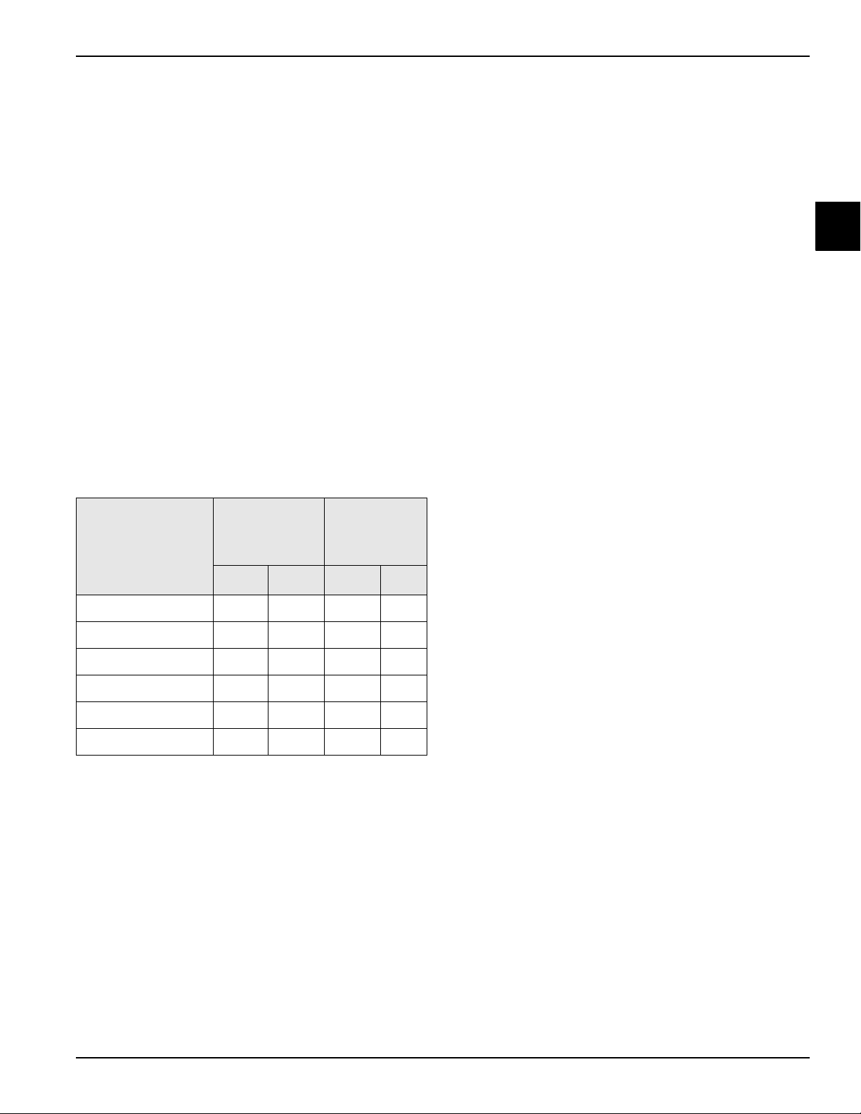
Table 1-1
One Dedicated Connection
Electrical
208-230/60/1 Air 25 21 2P 3W
208-230/60/1 Water 25 21 2P 3W
Max Fuse
Size
Min Circuit
Ampacity
Poles (P)
Wires (W)
This machine may be manufactured with other electrical
characteristics. Refer to the local Taylor distributor for
availability. For exact electrical information, see the data
label of the machine.
Air-Cooled
Clearance: A minimum of 6 in. (152 mm) is required on
both sides, with the back of the machine placed against
the wall to prevent recirculation of warm air. An optional
air discharge chute is available to direct heated air
exhaust upward. No clearance is required on the right
side if the air discharge chute is used.
Water-Cooled
Water inlet and drain connections are on the right side or
under the side of the base, 3/8 in. Female Pipe Taper
(FPT).
Dimensions
Width: 18-1/4 in. (464 mm)
Height: 34 in. (864 mm)
Depth: 32-1/4 in. (820 mm)
Counter Clearance: Rests on a plastic pad directly on a
counter top.
1
208-230/60/3 Air 20 15 3P 4W
208-230/60/3 Water 15 14 3P 4W
220-240/50/1 Air 25 19 2P 3W
380-415/50/3N~ Air 10 8 4P 5W
Approximate Weights
Net: 425 lb. (193 kg)
Crated: 471 lb. (214 kg)
Volume: 35.0 cu. ft. (0.99 cu. m)
Introduction
Models C708/C709/C716/C717
1-5
Page 10

INTRODUCTION
1
Figure 1-1
1-6
Models C708/C709/C716/C717
Introduction
Page 11

Model C709 Specifications
INTRODUCTION
Freezing Cylinder
One, 3.4 qt. (3.2 L)
Mix Hopper
One, 20 qt. (18.9 L)
Beater Motor
One, 1.5 HP
Refrigeration Machine
One, approximately 10,100 BTU/hr. compressor.
Refrigerant R449A.
Electrical
Table 1-2
One Dedicated Connection
Electrical
208-230/60/1 Air 25 19 2P 3W
208-230/60/3 Air 15 13 3P 4W
Max Fuse
Size
Min Circuit
Ampacity
Poles (P)
Wires (W)
This machine may be manufactured with other electrical
characteristics. Refer to the local Taylor distributor for
availability. For exact electrical information, see the data
label of the machine.
Air-Cooled
Clearance: A minimum of 6 in. (152 mm) is required on
both sides, with the back of the machine placed against
the wall to prevent recirculation of warm air. An optional
air discharge chute is available to direct heated air
exhaust upward. No clearance is required on the right
side if the air discharge chute is used.
Water-Cooled
Water inlet and drain connections are on the right side or
under the side of the base, 3/8 in. Female Pipe Taper
(FPT).
Dimensions
Width: 18-1/4 in. (464 mm)
Height: 34 in. (864 mm)
Depth: 32-1/4 in. (820 mm)
Counter Clearance: Rests on a plastic pad directly on a
counter top.
1
208-230/60/3 Water 15 13 3P 4W
220-240/50/1 Air 20 17 2P 3W
380-415/50/3N~ Air 8 7 4P 5W
Approximate Weights
Net: 414 lb. (188 kg)
Crated: 425 lb. (193 kg)
Volume: 35.0 cu. ft. (0.99 cu. m)
Introduction
Models C708/C709/C716/C717
1-7
Page 12

INTRODUCTION
1
Figure 1-2
1-8
Models C708/C709/C716/C717
Introduction
Page 13

Model C716 Specifications
INTRODUCTION
Freezing Cylinder
Two, 3.4 qt. (3.2 L)
Mix Hopper
Two, 20 qt. (18.9 L)
Beater Motor
Two, 1.5 HP
Refrigeration Machine
One, approximately 10,100 BTU/hr. compressor.
Refrigerant R449A.
Electrical
Table 1-3
Minimum
Circuit
Ampacity
Electrical
Maximum Fuse
Size
This machine may be manufactured with other electrical
characteristics. Refer to the local Taylor distributor for
availability. For exact electrical information, see the data
label of the machine.
Air-Cooled
Clearance: A minimum of 3 in. (76 mm) is required
around all sides. Install the deflector provided to prevent
recirculation of warm air.
Water-Cooled
Water inlet and drain connections are under the side of
the base, 1/2 in. Female Pipe Taper (FPT).
Dimensions
Width: 25-7/16 in. (646 mm)
Height: 60 in. (1524 mm)
Depth: 36-3/16 in. (919 mm)
Floor Clearance*: 4-3/4 in. (121 mm)
*Mounted on standard casters
1
Left Right Left Right
208-230/60/1 Air 30 25 23 20
208-230/60/1 Air, Syrup 30 25 25 20
208-230/60/1 Water 25 25 21 20
208-230/60/3 Air 20 15 16 13
208-230/60/3 Air, Syrup 20 15 18 13
380-415/50/3N~ Air 12 9 12 8
Approximate Weights
Net: 827 lb. (375 kg)
Crated: 942 lb. (427 kg)
Volume: 67.4 cu. ft. (1.91 cu. m)
Introduction
Models C708/C709/C716/C717
1-9
Page 14

INTRODUCTION
1
Figure 1-3
1-10
Models C708/C709/C716/C717
Introduction
Page 15
Model C717 Specifications
INTRODUCTION
Freezing Cylinder
Two, 3.4 qt. (3.2 L)
Mix Hopper
Two, 20 qt. (18.9 L)
Beater Motor
Two, 1.5 HP
Refrigeration Machine
One, approximately 10,100 BTU/hr. compressor.
Refrigerant R449A.
Electrical
Table 1-4
Minimum
Circuit
Ampacity
Electrical
Maximum Fuse
Size
This machine may be manufactured with other electrical
characteristics. Refer to the local Taylor distributor for
availability. For exact electrical information, see the data
label of the machine.
Air-Cooled
Clearance: A minimum of 3 in. (76 mm) is required
around all sides. Install the deflector provided to prevent
recirculation of warm air.
Water-Cooled
Water inlet and drain connections under the side of the
base, 1/2 in. Female Pipe Taper (FPT).
Dimensions
Width: 25-7/16 in. (646 mm)
Height: 60 in. (1524 mm)
Depth: 36-3/16 in. (919 mm)
Floor Clearance*: 4-3/4 in. (121 mm)
*Mounted on standard casters
1
Left Right Left Right
208-230/60/1 Air 30 25 22 19
208-230/60/1 Water 25 25 19 19
208-230/60/3 Air 15 15 15 12
208-230/60/3 Water 15 15 12 12
220-240/50/1 Air 20 20 18 17
380-415/50/3N~ Air 10 8 9 6
Approximate Weights
Net: 719 lb. (326 kg)
Crated: 824 lb. (374 kg)
Volume: 67.4 cu. ft. (1.91 cu. m)
Introduction
Models C708/C709/C716/C717
1-11
Page 16

INTRODUCTION
1
Figure 1-4
1-12
Models C708/C709/C716/C717
Introduction
Page 17

General Installation Instructions
INTRODUCTION
The following are general installation instructions. For
complete installation details, please see the check out
card.
NOTICE! Stationary machines which are not
equipped with a power cord and a plug or another device
to disconnect the machine from the power source must
have an all-pole disconnecting device with a contact gap
of at least 0.125 in. (3 mm) in the external installation.
Air-Cooled Machines
C708 and C709: These machines require a minimum of
6 in. (152 mm) air clearance on both sides, with the back
of the machine placed against the wall to prevent
recirculation of warm air. An optional air discharge chute
is available to direct heated air exhaust upward. No
clearance is required on the right side if the air discharge
chute is used.
C716 and C717: These machines require a minimum of
3 in. (76 mm) air clearance around all sides. Install the
deflector provided to prevent recirculation of warm air.
Beater Rotation
DANGER! The main power supply(s) to the
machine must be disconnected prior to performing any
installation, maintenance, or repairs. Failure to follow this
instruction may result in personal injury or death from
electrical shock or hazardous moving parts, as well as
poor performance or damage to the machine.
1. Remove the door assembly, beater, and scraper
blades.
2. Place a magnet over the door switch in the front
panel. This deactivates the safety feature which
prevents the operation of the machine when the door
is not installed.
3. Place the power switch in the ON position.
4. Press the Wash key on the control panel. This
activates the beater motor only.
5. Look into the freezing cylinder. The driveshaft should
be turning clockwise. (If necessary, lift the swing
panel to view rotation.)
1
Refrigeration
Main Compressor:
Air-cooled machines: 42 oz. (1,191 g) of R449A.
Water-cooled machines: 40 oz. (1,134 g) of R449A.
Gear Alignment and Rear Shell Bearings
1. Make certain the driveshaft(s) can easily slide in and
out of the female socket on the gear(s).
2. If a driveshaft is binding, the gear could be out of
alignment (loose). Check the bolts on the gear to
make sure they are tight.
3. Inspect the rear shell bearing for tightness. Make
sure the locking tab has been folded over to prevent
the nut from loosening.
6. Press the Wash key again to stop the beater motor.
Note: Repeat step 1 through step 6 for the other side
on models C716 and C717.
To correct rotation on a single-phase machine, exchange
leads inside the beater motor. (Follow the diagram
printed on the motor.)
To correct rotation on a three-phase machine,
interchange any two incoming power supply lines at
freezer main terminal block only.
DANGER! The main power supply(s) to the
machine must be disconnected prior to performing any
installation, maintenance, or repairs. Failure to follow this
instruction may result in personal injury or death from
electrical shock or hazardous moving parts, as well as
poor performance or damage to the machine.
Introduction
Models C708/C709/C716/C717
1-13
Page 18

INTRODUCTION
Pump Motor Rotation
1. Remove the air/mix pump assembly.
2. Connect power to the freezer and place the power
switch in the ON position.
3. Press the Pump button on the control panel. This
activates the pump motor only.
1
4. Observe the pump ball crank. It should be rotating
counterclockwise.
If rotation is not correct, refer to the wiring diagram on the
pump motor and re-wire accordingly.
Note: Repeat step 1 through step 4 for the other side
on Models C716 and C717.
DANGER! The main power supply(s) to the
machine must be disconnected prior to performing any
installation, maintenance, or repairs. Failure to follow this
instruction may result in personal injury or death from
electrical shock or hazardous moving parts, as well as
poor performance or damage to the machine.
Installation of Optional Syrup Rail
X48015-27 (C708 and C709 Only): The syrup rail can
only mount to the left side of the C708 or C709 if the top
air discharge chute is not used.
The syrup rail can be mounted to either the left or right
side of the C708 or C709 machines if a top air discharge
chute is used.
Perform the following steps to mount the syrup rail
on the side of a machine where a top air discharge
chute is not installed:
1. Remove the (4) panel screws as shown in Figure 1-5.
Electrical Connections
Each machine requires one power supply for each data
label on the machine. Check the data label(s) on the
machine for branch circuit overcurrent protection or fuse,
circuit ampacity and other electrical specifications. Refer
to the wiring diagram provided inside the control box for
proper power connections.
In the United States, this machine is intended to be
installed in accordance with the National Electrical Code
(NEC), ANSI/NFPA 70-1987. The purpose of the NEC
code is the practical safeguarding of persons and
property from hazards arising from the use of electricity.
This code contains provisions considered necessary for
safety. Compliance therewith and proper maintenance
will result in an installation essentially free from hazard.
In all other areas of the world, equipment should be
installed in accordance with the existing local codes.
Please contact your local authorities.
Stationary appliances which are not equipped with a
power cord and a plug or other device to disconnect the
appliance from the power source must have an all-pole
disconnecting device with a contact gap of at least 0.12
in. (3 mm) installed in the external installation.
Figure 1-5
2. Install the Mounting Assembly – Syrup Rail (X57317)
using the (4) Spacers (053600) and the (4)
Screws-1/4 20X3 Hex Cap (025984) with (4)
Washers (000655).
3. Install the (4) Plugs – Square Tubing (057381) in the
ends of the Mounting Assembly – Syrup Rail
(X57317).
4. Install the (3) Holding Collars (046551) using the (3)
Screws –10-32X3/4 Oval HD-SS.
5. Hang the Syrup Rail Assembly (048015-27) on the
holding collars.
1-14
Models C708/C709/C716/C717
Introduction
Page 19

INTRODUCTION
Perform the following steps to mount the syrup rail
on the side of a machine where a top air discharge
chute is installed:
1. Three holes must be created in the side of the chute
as shown in
tion 048014-DRW included with the Syrup Rail Kit.)
Figure 1-6. (See the Syrup Rail Instruc-
Syrup Rail Operating Instructions
1. Remove the stainless steel syrup jar with topping
pump from the syrup rail. Check the water level in the
well. Make sure the water is filled to the indicating
mark on the inside wall (16 oz. [474 mL]). Check the
water level daily.
2. Place the heater switch in the ON position. The
heating process will take approximately 1-1/4 hours.
3. Prepare a pail with an approved 100 PPM sanitizing
solution. Use warm water and follow the
manufacturer's specifications.
4. Sanitize the pump by placing the entire assembly in
the solution and pump the solution through the pump
until sanitized.
5. Fill the heated and room-temperature syrup jars with
toppings. Place the topping pump in the heated syrup
jar. Sanitize the ladle and place it in the roomtemperature jar.
1
Figure 1-6
2. Install the (3) Nutserts (021106) in the panel.
3. Install the (3) Holding Collars (046551) using the (3)
Screws-10-32X3/4 Oval HD-SS.
4. Hang the Syrup Rail Assembly (048015-27) on the
holding collars.
Introduction
Models C708/C709/C716/C717
1-15
Page 20

INTRODUCTION
Running Specifications
Pressures/Temperatures
The following are the Taylor recommended settings for
various components within these models. The freezers in
this manual use refrigerant R449A.
Note: These settings apply to both sides of the C716
1
and C717 machines.
EPR Valve = 60 psi (414 kPa)
OPR Valve = 21 psi (145 kPa)
Expansion Valve (AXV)*
Air-Cooled: 16.5 psi (114 kPa)
Water-Cooled: 16.5 psi (114 kPa)
*For a normal product of 16°F to 18°F (-8.8°C to -7.7°C).
Expansion Valve Adjustment (AXV)
Place your pressure gauge on the access valve on the
suction line (located at the compressor).
Adjust higher or lower by turning the adjustment screw.
Clockwise turns raise the pressure and counterclockwise
turns lower the pressure.
Note: Make expansion valve adjustments with mix in
the cylinder and the freezer in the Auto mode. Make sure
to allow adequate time for the pressure to stabilize.
Low-Side (Suction)
Suction pressure equals expansion valve setting.
High-Side (Discharge)
High-side pressure varies for air-cooled machines,
depending on the ambient temperature.
Table 1-5
Ambient Temperature
°F °C psi (kPa)
70° 21.1°
80° 26.7°
90° 32.2°
100° 37.8°
Normal Operating Head
Pressures
240 to 270
(1,655 to 1,862)
270 to 300
(1,862 to 2,069)
300 to 340
(2,069 to 2,344)
340 to 380
(2,344 to 2,620)
Water Valve
On a water-cooled machine, the water valve should be
set to maintain a compressor head pressure of 255 psi
(1,758 kPa).
Water Valve Adjustment
Place your pressure gauge on the high-side access port
of the compressor. Turning the adjustment stem on the
water valve clockwise lowers the pressure,
counterclockwise raises the pressure.
Note: Make this adjustment with mix in the cylinder and
the freezer in the Auto mode. Make sure to allow
adequate time for pressure to stabilize.
1-16
Models C708/C709/C716/C717
Introduction
Page 21

Remote Monitoring Commissioning
Taylor Gateway Connecting to Wi-Fi
1. From Taylor machine enable Gateway Access Point:
a. Enter the Manager Menu.
b. Scroll down to Enable Wi-Fi menu.
INTRODUCTION
c. Enable the feature.
d. This will activate the Gateway Access Point for 10
minutes, allowing a user to connect directly to the
Gateway.
2. From a user device (laptop, cellphone, tablet, etc.)
connect to the taylor-gw access point through the
Wi-Fi setting on the device.
a. This access point may not be broadcast so the
user may have to use the Add Network function.
b. Enter the password to connect to the access
point.
3. Once the connection is established open an internet
browser.
4. Enter 192.168.2.1:8081 into the browser bar.
a. A warning page may be displayed (examples
follow).
b. This warning is due to the configuration page's
certificate and it is ok to proceed.
c. By clicking Details or Advanced the user can
proceed to the URl despite the warning.
1
Figure 1-8
d. The Gateway configuration webpage will then be
displayed.
Introduction
Figure 1-7
5. Click on the Wi-Fi tab:
a. Enter the name of the customer Access Point you
would like to connect to (Customer’s Wi-Fi).
b. Enter the corresponding password.
c. Click Submit to save the changes.
d. Click reboot to reboot the Gateway, at which time
it will connect to the customer's Wi-Fi.
Models C708/C709/C716/C717
Figure 1-9
1-17
Page 22

INTRODUCTION
1
Figure 1-10
6. Confirm connection to customer access point (Wi-Fi).
3 blinks: WiFi error
• Confirm the store's WiFi is operational:
• Using a computer, tablet, or phone, try to
connect to any website on the store's WiFi.
• Confirm store's current WiFi password:
• If recently changed, follow the procedures
to reconnect the gateway board to the
store's WiFi.
• Confirm the store's current SSID (WiFi name):
• If recently changed, follow the procedures
to reconnect the gateway board to the
store's WiFi.
• Confirm the WiFi signal strength using an app
on a phone or tablet:
• Minimum DB level -70 dBm
• Suggested apps
• Android : WiFi Analyzer
• iOS: AirPort Utility
Note: Go to app settings and turn on WiFi Scanner
options.
Remote Monitoring Gateway Board
Troubleshooting
To troubleshoot issues with the remote monitoring
gateway board, observe the blink patterns of the blue
LED light at D1. The light will illuminate for approximately
1 second, followed by the code blinks.
LED not lit: No power to the gateway board
• Confirm there is 24V to the power cable at the
connector end.
• Confirm the power cable is correctly connected
to the transformer.
• Replace the gateway board.
2 blinks: No communication between gateway and
UVC4 boards
• Confirm the cable between the gateway and
UVC4 boards is connected properly and not
damaged.
• Confirm UVC4 is functioning correctly.
• Confirm the UVC4 has the correct software
version for remote monitoring system:
• C708/C716: Minimum version 2.03
• C709/C717: Minimum version 2.03
4 blinks: Server connection error
• Follow the procedures to reconnect the gateway
board to the store's WiFi.
• Replace the gateway board.
1-18
Models C708/C709/C716/C717
Introduction
Page 23

To the Operator
1
11
10
5
6
4
3
2
6
4
5
11
7
8
9
3
3
2
4
6
5
7
8
9
10
1
C716/C717
INTRODUCTION
1
C708/C709
Figure 1-11
Item Description
1Power Switch
2 Liquid Crystal Display
3Keys
4 Mix-Out Indicator
5 Standby Indicator
6 Mix-Low Indicator
7 SEL (Select) Key
8 Menu Key
9 Brush Clean Counter
10 Arrow Keys
11 Syrup Heater Key
Note: Models C709 and C717 do not have mix pump Keys.
Introduction
Figure 1-12
Models C708/C709/C716/C717
1-19
Page 24

INTRODUCTION
6
8
9
10
1
2
3
4
12
13
11
5
1
2
3
4
5
8
6
7
9
10
11
13
12
14
15
16
17
18
19
20
21
C708/C709
1
C716/C717
Figure 1-13
Figure 1-14
Symbol Definitions
To better communicate in the international arena, symbols have replaced words on many of our operator switches,
keys, function, and fault indicators. Your Taylor machine is designed with these international symbols.
Introduction
1-20
Models C708/C709/C716/C717
Page 25

INTRODUCTION
10354
Item Description
1 Auto Key
2Heat Key
3Wash Key
4 Mix Pump Key (C708/C716 Only)
5 Mix-Out Indicator
6 Standby Key
7 Topping Heater Key-Right Side
(C716/C717 Only)
8 Mix-Low Indicator
9 SEL (Select) Key
10 Menu Key
11 Brush Clean Counter Display
Power Switch
When placed in the ON position, the power switch allows
control panel operation.
Item Description
12 Down Arrow Key
13 Up Arrow Key
*14 Topping Heater Key
*15 Standby Key
*16 Mix-Out Indicator
*17 Mix-Low Indicator
*18 Mix Pump Key
*19 Wash Key
*20 Heat Cycle Key
*21 Auto Key
*Left side of C716/C717 only.
Heat Cycle Key—When illuminated, the freezer is in a
heat cycle. Press the Heat Cycle key (if enabled) to start
a Heat cycle. If disabled, the Heat Cycle key is
inoperable. By default, the Heat Cycle key is enabled.
1
Liquid Crystal Display (LCD)
The Liquid Crystal Display (LCD) is located on the front
control panel. During normal operation, the display is
blank. The display shows menu options and notifies the
operator if a fault is detected. On international models,
the display shows the temperature of the mix in each
hopper.
Indicator Lights
Mix-Low—When the Mix-Low indicator illuminates, the
mix hopper has a low supply of mix and should be refilled
as soon as possible.
Mix-Out—When the Mix-Out indicator illuminates, the
mix hopper is almost completely exhausted and has an
insufficient supply of mix to operate the machine. At this
time, the Auto mode is locked out and the machine will be
placed in the Standby mode. To initiate the refrigeration
system, add mix to the mix hopper and press the Auto
key. The machine will automatically begin operation.
Brush Clean Counter—When the Brush Clean Counter
display counts down to 1, the machine must be
disassembled and brush-cleaned within 24 hours.
Adjustable Draw Handle
The adjustable draw handle(s) provides the best portion
control for consistent high quality and helps control food
costs. The draw handle should be adjusted to provide a
flow rate of 5 oz. to 7-1/2 oz. (142 g to 213 g) of product
by weight per 10 seconds. To increase the flow rate, turn
the screw clockwise. To decrease the flow rate, turn the
screw counterclockwise. (See
Figure 1-15.)
Introduction
Models C708/C709/C716/C717
Figure 1-15
1-21
Page 26
INTRODUCTION
Beater Motor Overload
C708/C709—The beater motor overload is located in the
service panel on the left side.
C716/C717—The beater motor overloads are located in
the rear panel.
The overload protects the beater motor from an overload
condition. Should an overload occur, the reset
1
mechanism will trip. To properly reset the freezer, place
the power switch in the OFF position. Press the RESET
button firmly. Turn the power switch to the ON position.
Press the Wash key and observe the freezer's
performance.
CAUTION! DO NOT use metal objects to press
the reset button. Failure to follow this instruction may
result in electrocution.
If the beater motor is turning properly, press the Wash
key to cancel the cycle. Press the Auto key to resume
normal operation. If the freezer shuts down again,
contact your authorized Taylor service technician.
Air/Mix Pump Reset Mechanism
(C708 and C716 Only)
C708—The RESET button for the pump is located on the
left side.
C716—The RESET buttons for the pumps are located in
the rear panel.
The reset protects the pump from an overload condition.
Should an overload occur, the reset mechanism will trip.
To reset the pump, press the RESET button firmly.
CAUTION! DO NOT use metal objects to press
the reset button. Failure to follow this instruction may
result in electrocution.
Condenser Fan Motor
The condenser fan motor is driven by the software.The
L1 to the fan is connected to the interface board at J6-6.
The condenser fan is programmed to run any time the
compressor is on and to stay running for 30 seconds after
the compressor cycles off. The fan motor runs constantly
through heat cycles regardless of the compressor status,
then cycles off 30 seconds after the compressor cycles
off at the end of the Heat Treatment Cycle and the
subsequent Standby mode.
1-22
Models C708/C709/C716/C717
Introduction
Page 27

Section 2:
Controls
• Universal Control Programming
• Heat Treatment Cycle
• Heat Treatment Graph
• Freezer Lock-Out
• Power Interrupt
• Pump Operation
• Timers
• Jumper Pin Charts
• Beater Stir Cycles
• Setting Viscosity
• C708/C709 Control Overview
• C716/C717 Control Overview
Controls
• Universal Control Board
• Refrigeration System—Hot Gas Treatment
• Checking and Setting Refrigeration Valves
• Refrigeration Schematic
• Refrigeration System Components
Models C708/C709/C716/C717
2-1
Page 28

CONTROLS
Initializing
Language
Initializing
System Data
Initializing
Config Data
Initializing
Lockout Data
Universal Control Programming
Operating Screen Descriptions
The LCD located in the center of the control panel is
normally blank during daily operation of the machine. The
display is activated when the SEL key or the Manager's
Menu is selected. The display screen will also alert the
operator of specific faults detected by the control.
Note: The displays illustrated in this section are those
seen on the Models C708/C709. The Model C716/C717
2
versions may vary slightly.
Power Up Memory (Initializing)
The seven-segment display should display 00 during the
initializing sequence.
When the machine is powered, the control system will
initialize to perform a system check. The screen will
display Initializing. There are four types of data the
system checks: Language, System Data, Configuration
Data, and Lockout Data.
Language Initialization
The universal control (UVC) platform supports multiple
languages by keeping specific strings in battery-backed
random-access memory (RAM). After power-up or a
central processing unit (CPU) reset, the strings are
tested to see if the language strings are present and not
corrupted. If the strings are present and not corrupted,
initialization continues. Otherwise, the operator is
prompted to select a language. While language strings
are being checked for integrity, the following screen is
displayed.
System Data
System data is protected separately from the rest of the
data in memory. System data includes variables that
change frequently such as the mode the machine is in,
lockout status, serving counters, fault codes, and others.
While system data is being checked, the following screen
is displayed.
If the system data is corrupted, the machine is set to
OFF, the serving counters are set to zero, and the faults
are cleared. A SYSTEM CRC ERR fault is set/displayed.
An acknowledgment is required (press SEL key).
Configuration Data
Configuration data is separate from the rest of the data in
the memory. Configuration data is information entered
through operator and service menus. While configuration
data is being checked the following screen is displayed.
If configuration data is corrupted, all user and service
settings are set to defaults and a CONFIG CRC ERR
fault is set/displayed. The system will continue to operate
in its previous mode, but according to default settings.
Note: If there is a language initialization fault, the
machine will force a language selection prior to the
initializing sequence. The standard menu LEDs should
light, as if it were in a menu. If a language has been
selected, the machine is powered down, the machine
should not ask for a language unless there is another
language initialization fault. English is the factory default
setting.
2-2
Lockout Data
Lockout data is protected separately from the rest of the
data in the memory. While the lockout data is being
checked, the following screen is displayed.
If lockout data is corrupted, all lockout history data is
cleared. A LOCKOUT CRC ERR fault is displayed.
After the memory integrity has been tested, the safety
timeout screen is displayed.
Models C708/C709/C716/C717
Controls
Page 29

CONTROLS
SAFETY TIMEOUT
ANY KEY ABORTS
POWER SWITCH OFF
Ŧ = Ŧ = Ŧ = Ŧ = Ŧ = Ŧ
UNIT CLEANED
UNIT CLEANED
DO NOT DRAW
HOT PRODUCT
Heat Cycle Data
Heat cycle data is checked separately from the rest of the
data in memory. Each individual Heat cycle data record is
monitored for corruption individually. At the start of a Heat
cycle, the previous Heat cycle data record is cleared and
data for the heat cycle is written to it. The current Heat
cycle data is displayed as the first heat cycle record in the
HEAT CYCLE DATA menu option. The Heat cycle data
records are checked for integrity when the record is
accessed, presently only through the HEAT CYCLE
DATA menu option. (For additional Heat cycle data
information, see
Once the system has initialized, the number of days until
brush-cleaning is required is indicated on the control
panel. The SAFETY TIMEOUT screen is displayed with
the alarm on for 60 seconds or until any control key is
pressed.
page 2-10.)
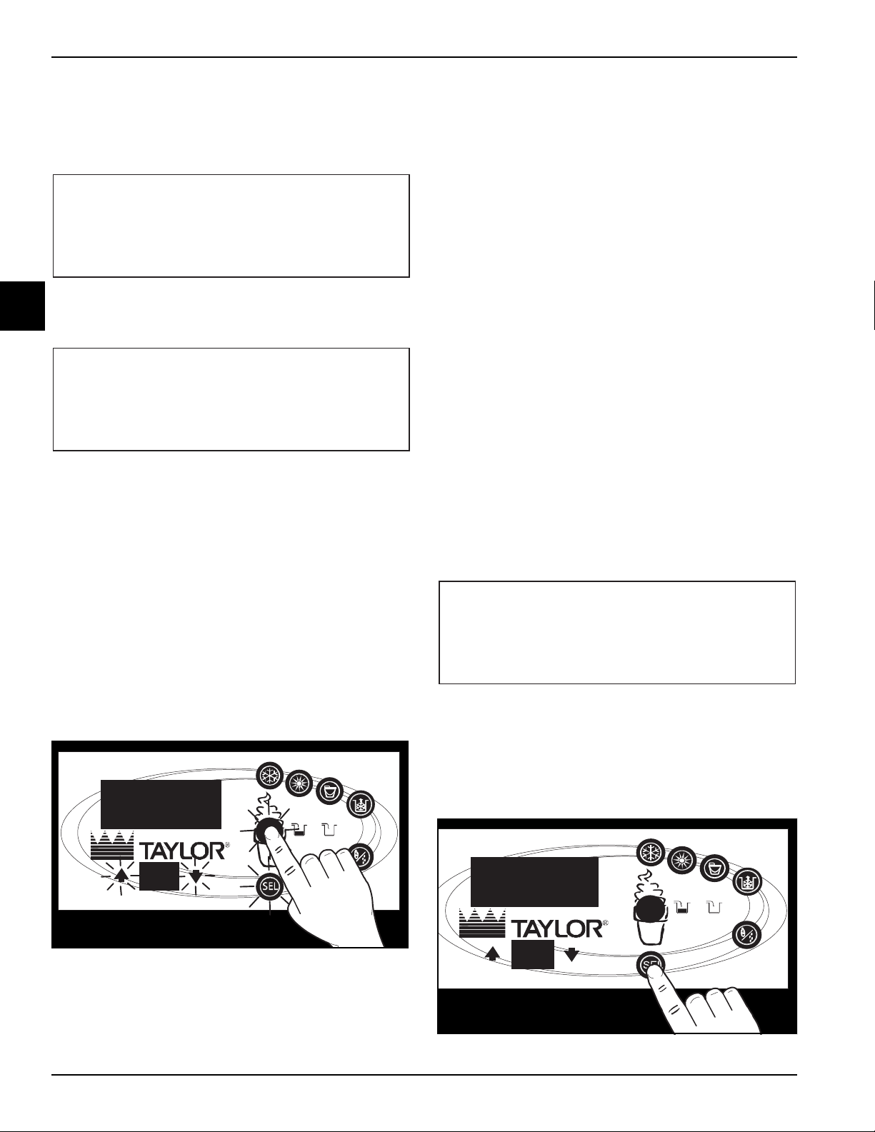
Heat Treatment Cycle
The Heat Cycle key on the control panel illuminates
throughout the Heat Treatment Cycle. Two warning
messages will be displayed on the screen. DO NOT
DRAW is displayed when the mix temperature is below
130°F (54.4°C).
2
When the temperature of the mix is above 130°F
(54.4°C) the screen will display a message indicating that
HOT PRODUCT is in the machine.
Power Switch OFF
After the safety timeout has been completed and the
power switch is off, the following screen is displayed:
Power Switch ON
When the power switch is placed in the ON position, the
control panel keys become operative. The LCD will be
either blank or indicate that the machine has been
cleaned.
WARNING! DO NOT attempt to draw product or
disassemble the machine during the Heat Treatment
cycle (if equipped). The product is hot and under extreme
pressure. Severe burns from hot product may result if this
instruction is not followed.
In the Heat Treatment Cycle, the mix temperature in the
hopper and freezing cylinder must be raised to 151°F
(66.1°C) within 90 minutes.
When the Heat Treatment Cycle is complete, the freezer
goes into the holding phase of the cycle. The holding
phase keeps the temperature above 151°F (66.1°C) for a
minimum of 35 minutes for UVC3 machines, and 30
minutes for UVC4 machines.
The final phase of the Heat Treatment Cycle is the
cooling phase. The freezer must cool the mix below 41°F
(5°C) within 90 minutes.
When the entire Heat Treatment Cycle has been
completed, the Heat Cycle key will no longer be
illuminated and the machine enters the Standby mode
(Standby key illuminates). The machine can then be
placed in Auto mode or left in Standby mode.
Controls
Models C708/C709/C716/C717
2-3
Page 30
CONTROLS
HOPPER 21.0
UNIT CLEANED
ARE YOU SURE
>Yes
No
13398BR
ENTER ACCESS CODE
83 0 9
__
13399
International Models Only:
Some international models continuously display the
temperature of the mix hopper when the power switch is
in the ON position.
If the control is set for international configuration, the
following screen appears when the Heat Cycle key is
2
pressed.
Use the Up Arrow or Down Arrow key to move the cursor
to Yes. Press the SEL key to immediately start a Heat
Treatment Cycle.
Note: The machine must be in Auto or Standby mode
and have sufficient mix in the hopper before the machine
can successfully enter the Heat mode of operation.
• Down Arrow key—decreases the value above
the cursor and scrolls downward in text
displays.
• SEL—advances the cursor position to the right
and selects menu options.
There is a 2-minute time-out in effect during the
Manager’s Menu. While in the Manager’s Menu, if no
activity occurs within a 2-minute period, the display will
exit to the main menu. There is one exception to this
time-out, and that is the CURRENT CONDITIONS
display.
Note: The machine will continue operation in the mode
it was in when the menu was selected. However, the
control keys will not be lit and are non-functional when
the Manager’s Menu is displayed. The control keys are
functional in the Manager’s Menu when the CURRENT
CONDITIONS screen is displayed. (See Current
Conditions on
page 2-11.)
Entering Access Code
With the ENTER ACCESS CODE screen on the display,
use the SEL key to set the first code number in the cursor
position. When the correct number is selected, press the
SEL key to move the cursor to the next number position.
Manager's Menu
Use the Manager's Menu to enter the operator function
displays. To access the menu, press the Menu (Cone)
key, on the control panel. The Arrow keys, the SEL key
and the Menu key will be lit when the ACCESS CODE
screen is displayed.
Figure 2-1
In the menu program, the Arrow keys and the SEL key will
function as menu keys:
• Up Arrow key—increases the value above the
cursor and scrolls upward in text displays.
Enter the access code numbers (8309) until all four
numbers are displayed, then press the SEL key. The
Manager’s Menu list will display on the screen, provided
the correct access code is entered.
If an incorrect access code is entered, the display will exit
the menu program when the SEL key is pressed.
Figure 2-2
2-4
Models C708/C709/C716/C717
Controls
Page 31

Manager’s Menu Options
SERVINGS COUNTER
0
> Next
Reset Counters
ARE YOU SURE?
Yes
>No
SET CLOCK
12:01 00/00/00
NO CHANGES ALLOWED
Press Any Key
SET CLOCK
12:01 00/00/0000
Change
> Exit
SET CLOCK
12
:01 00/00/0000
> Exit
Press the Arrow keys to move up or down through the
menu. Select a menu option by pressing the SEL key.
Exit the menu program by selecting EXIT FROM MENU
or press the Menu key.
The following menu options are listed in the Manager's
Menu.
EXIT FROM MENU
SERVINGS COUNTER
SET CLOCK
AUTO HEAT TIME
AUTO START TIME
AUTO STANDBY TIME
AGITATOR OPERATION
MIX LEVEL AUDIBLE
FAULT DESCRIPTION
CONTROLS
Set Clock
The SET CLOCK screen allows the manager or service
technician to adjust the control clock date and time. The
date and time may only be changed after the freezer has
been manually cleaned but before it has been placed in
the Auto or Standby mode. The following message will be
displayed if the SET CLOCK option is selected when the
machine is not in a brush-clean state.
2
FAULT HISTORY
LOCKOUT HISTORY
HEAT CYCLE SUMMARY
HEAT CYCLE DATA
SYSTEM INFORMATION
CURRENT CONDITIONS
Exit From Menu
Selecting EXIT FROM MENU exits the Manager's Menu
and returns the control panel keys to normal operation.
Servings Counter
Use the SERVINGS COUNTER screen to check or reset
the number of servings dispensed from the machine. The
SERVINGS COUNTER automatically resets to zero
when the machine is brush-cleaned.
To change the date or time, select the SET CLOCK
option in the menu. Press the Up Arrow key to advance
the cursor from Exit to Change, then press the SEL key
to select the Change option.
Change the time by pressing the Up Arrow key with the
cursor under the hour position. Move the cursor to the
minutes position by pressing the SEL key. Once the
correct minutes are entered, press the SEL key to
advance the cursor to the month.
Reset the SERVINGS COUNTER by pressing the SEL
key to advance to the next screen. Press the Up Arrow
key to move the cursor to Yes and press the SEL key.
The servings counter will reset to zero and exit back to
the Manager's Menu.
Controls
Enter the correct month, day, and year. Then press the
SEL key to advance to the DAYLIGHT SAVING TIME
screen.
Models C708/C709/C716/C717
2-5
Page 32

CONTROLS
DAYLIGHT SAVING TIME
ENABLED
> Enable
Disable
MAR Second Sunday
NOV First Sunday
Change
> Exit
DST START MONTH
> MAR
APR
MAY
DST START WEEK
> Second Sunday
Third Sunday
Fourth Sunday
DST END MONTH
> NOV
DEC
DST END WEEK
> First Sunday
Second Sunday
Third Sunday
AUTO HEAT TIME
00:00
Change
> Exit
AUTO HEAT TIME
00
:00
Pressing the Up Arrow or Down Arrow keys moves the
cursor to Enable or Disable. Pressing the SEL key next to
Disable selects that option and returns to the Manager’s
Menu. Pressing the SEL key next to Enable selects that
option and displays the next screen.
2
If the correct Sunday for the time change is not
displayed, select Change. Pressing the SEL key with the
cursor next to Change displays the third screen. Press
the Up Arrow or Down Arrow key to move the cursor to
the appropriate month for the start of daylight saving time
(DST).
Pressing the SEL key next to the appropriate month will
display the following screen. Press the Up Arrow or Down
Arrow key to move the cursor to the appropriate week for
the end of DST.
Pressing the SEL key selects the week with the cursor
next to it and returns to the Manager’s Menu.
Auto Heat Time
The AUTO HEAT TIME screen allows the manager to set
the time of day in which the Heat Treatment Cycle will
automatically start.
To set the AUTO HEAT TIME, press the Up Arrow key to
move the cursor to Change. Then press the SEL key.
The screen will display the time with the cursor under the
hour position.
Pressing the SEL key with the arrow next to the
appropriate month will display the following screen:
Pressing the Up Arrow or Down Arrow key moves the
cursor to the appropriate week for the start of daylight
savings time. Pressing the SEL key next to the
appropriate week will display the following screen. Press
the Up Arrow or Down Arrow key to move the cursor to
the appropriate month for the end of DST.
2-6
Press the Arrow keys to increase or decrease the hour to
the desired setting. Then move the cursor to the minutes
position by pressing the SEL key. Adjust the setting for
minutes. Then press the SEL key to save the setting and
return to the AUTO HEAT TIME screen. Press the SEL
key to exit the screen and return to the menu.
Auto Start Time
The AUTO START TIME option allows the manager to
set the time of day at which the machine automatically
enters the Auto mode from the Standby mode. The
machine must be in the Standby mode without a freezer
lock condition in order to auto start at the programmable
time. The AUTO START TIME can also be disabled and
require starting the Auto mode manually.
Models C708/C709/C716/C717
Controls
Page 33

Enable the AUTO START TIME by pressing the Up Arrow
AUTO START TIME
DISABLED
Enable
> Disable
AUTO START TIME
00:00
Change
> Exit
AUTO START TIME
00
:00
AUTO STANDBY TIME
DISABLED
> Enable
Disable
AUTO STANDBY TIME
00:00
Change
> Exit
AUTO STANDBY TIME
00
:00
AGITATOR OPERATION
> Standard operation
with Hopper Refrig
Exit
key to move the cursor up to Enable. Press the SEL key
to advance to the next screen.
Program the AUTO START TIME by pressing the Up
Arrow key to move the cursor to Change. Press the SEL
key to advance to the next screen.
CONTROLS
Program the AUTO STANDBY TIME by pressing the Up
Arrow key to move the cursor to Change. Press the SEL
key to advance to the next screen.
Use the Arrow keys to program the AUTO STANDBY
TIME by increasing or decreasing the hour setting above
the cursor. Press the SEL key to advance the cursor and
program the minutes setting. Press the SEL key to return
to the previous screen with the new time setting
displayed. Press the SEL key to exit the screen and
return to the menu.
2
Use the Arrow keys to program the AUTO START TIME
by increasing or decreasing the hour setting above the
cursor. Press the SEL key to advance the cursor and
program the minutes setting. Press the SEL key to return
to the previous screen with the new time setting
displayed. Press the SEL key to exit the screen and
return to the menu.
Auto Standby Time
The AUTO STANDBY TIME option allows the manager to
set the time of day at which the machine automatically
enters the Standby mode from the Auto mode. This
allows power saving during slow sales. By default, this
feature is disabled.
Enable the AUTO STANDBY TIME by pressing the Up
Arrow key to move the cursor up to Enable. Press the
SEL key to advance to the next screen.
Agitator Operation
The AGITATOR OPERATION option allows the manager
to select either continuous or intermittent agitator
operation. Agitator Operation may be set to operate in
the Standard mode or with hopper refrigeration. In the
Standard mode, the agitator operates during Auto mode,
Standby mode, and Heat Treatment Cycle. In the With
Hopper Refrig mode, the agitator runs only when the
hopper is refrigerating and during the Heat, Hold, and
Soak phases of a Heat Treatment Cycle and the Cool
phase of a Heat Treatment Cycle if the hopper is
refrigerating. The default is standard operation.
Use the Arrow keys to move to the desired operation and
press the SEL key to accept the selection.
Mix Level Audible
The MIX LEVEL AUDIBLE option, when enabled, will
alert the operator with an audible tone when there is
Mix-Low or Mix-Out condition. The following screen is
displayed upon selecting this option:
Controls
Models C708/C709/C716/C717
2-7
Page 34

CONTROLS
MIX LEVEL AUDIBLE
DISABLED
> Enable
Disable
FAULT DESCRIPTION
NO FAULT FOUND
FAULT HISTORY 1
00/00/00 00:00
REASON
> Exit
LOCKOUT HISTORY 1
00/00/00 00:00
REASON
> Exit
Disable the audible tone feature by pressing the Down
Arrow key to move the cursor to Disable. Press the SEL
key to save the new setting and return to the menu. The
control panel icons for Mix-Low and Mix-Out will
illuminate as the mix level drops in the hopper, but the
audible tone will be disabled.
2
Fault Description
The FAULT DESCRIPTION screen lists any faults
detected by the control and allows the manager or
service technician to clear them from the screen. When a
fault is detected, it is displayed on the second and/or third
line.
Note: Three codes have been set up to assist in
diagnosing bad thermistor probes. If a probe has shorted
(resistance less than 1 ohm), SHRT will display for its
respective machine location. If the probe is open
(resistance above 1 megohm), OPEN will display. If the
actual probe environment exceeds 200°F (93°C), the
respective screen display location will read OVER,
indicating the temperature is out of range.
COMP ON TOO LONG—The compressor run time
exceeded the 11-minute timer.
Fault History
The FAULT HISTORY screen will display up to 100 faults
that have occurred. The most recent fault is displayed on
screen 1. The date, time, and fault description is
displayed on each screen.
Pressing the SEL key displays the next fault found or
returns to the Manager's Menu if no other faults exist.
Pressing the SEL key any time faults are displayed will
clear the faults, if corrected, upon returning to the menu
screen.
Listed below are variable messages which will appear,
along with an explanation for the corrective action.
NO FAULT FOUND—There was no fault found in the
freezer. Nothing will appear on the screen after this
variable message appears.
BEATER OVERLOAD—Place the power switch in the
OFF position. Wait 5 minutes for the machine to cool.
Press the beater reset button firmly. Place the power
switch in the ON position and restart in Auto mode.
COMPRESSOR HPCO—Place the power switch in the
OFF position. Wait 5 minutes for the machine to cool.
Place the power switch in the ON position and restart in
Auto mode.
HOPPER THERMISTOR BAD—Place the power switch
in the OFF position. (See note below.)
Lockout History
The LOCKOUT HISTORY screen displays a history of
the last 100 soft locks, hard locks, brush-clean dates, or
aborted heat cycles. Page numbers are indicated in the
upper right corner. Page 1 always contains the most
recent failure.
The second line of the screen displays the date and time
a failure occurs. The third line indicates the reason for a
failure, or will indicate if a successful brush-cleaning has
occurred. Some failures occur with multiple reasons.
When this occurs, a page will be generated for each
reason.
Use the Arrow keys to move forward or backward to view
each screen. Listed below are the variable messages
that may appear.
BARREL THERMISTOR BAD—Place the power switch
in the OFF position. (See note below.)
2-8
Models C708/C709/C716/C717
Controls
Page 35

CONTROLS
POWER FAILURE
PRESS SEL KEY
Faults Occurring Entering a Heat Treatment
Cycle
POWER SWITCH OFF—The power switch is off.
AUTO OR STBY OFF—The control was not in the Auto
or Standby mode.
MIX-OUT FAILURE—A Mix-Out condition was present.
NO HEAT CYCLE TRIED—The Auto Heat Time was set
to attempt a heat cycle more than 24 hours after the last
successful Heat cycle.
Faults Occurring While in Heat Mode
HEAT MODE FAILURE—The maximum allowable heat
mode time exceeded 90 minutes.
COOL MODE FAILURE—The maximum allowable cool
mode time exceeded 90 minutes for UVC3 machines or
120 minutes for UVC4 machines.
TOTAL TIME FAILURE—The maximum allowable total
heat treatment time exceeded 4 hours.
BRUSH CLEAN TIMEOUT—The total days in operation
exceeded the brush-clean cycle setting.
(L/R) BRL>41F (5C) AFTER PF—The mix temperature in
the freezing cylinder (barrel) was above 41°F (5°C) more
than 4 hours following a power failure.
(L/R) HPR>45F (7C) AFTER 1 HR—The mix
temperature in the left or right hopper was above 45°F
(7°C) more than 1 hour.
(L/R) BRL>45F (7C) AFTER 1 HR—The mix temperature
in the left or right freezing cylinder (barrel) was above
45°F (7°C) more than 1 hour.
(L/R) HPR>59F (15C)—The mix temperature in the
hopper exceeded 59°F (15°C).
(L/R) BRL>59F (15C)—The mix temperature in the
freezing cylinder (barrel) exceeded 59°F (15°C).
Error Messages
Error messages are faults that cannot be monitored after
they are detected. An example would be if a CRC error
occurs. The software corrects it and then reports it to the
operator. Once the error is reported, it stops monitoring it.
The following are a list of these errors.
2
POWER SWITCH OFF—The power switch was turned
off during the Heat cycle.
POWER FAIL IN H/C—A power failure occurred during
the Heat Treatment Cycle.
MIX-LOW FAILURE—The mix level in the hopper is too
low for a successful Heat cycle.
BEATER OVLD H/C—The overload tripped for the beater
motor.
BRL THERM FAIL—The thermistor sensor for the
freezing cylinder failed.
HOPPER THERM FAIL—The thermistor sensor for the
hopper failed.
HPCO H/C—The high-pressure switch opened during
the Heat Treatment Cycle.
Faults Occurring While in Auto Mode
(L/R) HPR>41F (5C) AFTER 4 HR—The mix
temperature in the hopper was above 41°F (5°C) more
than 4 hours.
(L/R) BRL>41F (5C) AFTER 4 HR—The mix temperature
in the freezing cylinder (barrel) was above 41°F (5°C)
more than 4 hours.
(L/R) HPR>41F (5C) AFTER PF—The mix temperature
in the hopper was above 41°F (5°C) more than 4 hours
following a power failure.
POWER FAILURE
RESET TO DEFAULTS
CONFIG CRC ERROR
LOCKOUT CRC ERROR
HC DATA CRC ERROR
SYSTEM CRC ERROR
EEPROM CRC ERROR
CORRUPTED LANGUAGE
HOPPER OVER TEMP
BARREL OVER TEMP
PRODUCT DOOR OFF
LANGUAGE TOO SHORT
MISSING LANGUAGE
These errors will be shown on the top line of the display.
The fourth line will show PRESS SEL KEY. When the
SEL key is pressed, the error displayed will be cleared. If
other errors exist, the sequence will be repeated.
Controls
Models C708/C709/C716/C717
2-9
Page 36

CONTROLS
HEAT CYCLE SUMMARY
0CH ECNIS SRH
0051 ECNIS SRH
0CB ECNIS CH
HEAT TREAT CYCLE
00/00 00:00 00:00
No fault found
1
H: 40.9 B:26.3 L
HEAT OVER COOL PEAK
1:12 0:49 h 1:19 161.0
0:46 1:11 b 0:15 169.7
H: 38.0 B:23.7 R
HEAT OVER COOL PEAK
1:09 0:52 h 1:11 161.2
0:66 1:00 b 0:11 169.9
Heat Cycle Summary
The HEAT CYCLE SUMMARY screen displays the hours
since the last Heat Treatment Cycle, the hours since the
product temperature was above 150°F (65.6°C), and the
number of Heat Treatment Cycles completed since the
last brush-clean date.
2
Heat Treat Cycle Data
The HEAT TREAT CYCLE screen contains a record of up
to 366 Heat Treatment Cycles. The most recent Heat
cycle data will be shown first.
Each Heat cycle record has three screens. The first
screen displays the month and day of the Heat cycle, the
start time and end time, and the fault description. The
bottom line displays the record number and indicates if a
power failure occurred during the Heat cycle (POWER
FAILURE IN HC).
COOL = Total time the hopper (h) and barrel (b)
temperature was above 41°F (5°C) during the Cool
phase.
PEAK = Highest temperature reading for the hopper (h)
and barrel (b) during the Heat Treatment Cycle.
The HEAT time indicates the amount of time taken in
each zone to reach 150.9°F (66.1°C). Each zone must
remain above 150°F (65.6°C) for a minimum of
35 minutes.
Press the Up Arrow key to advance to the next page or
the Down Arrow key to view the previous page. A heat
cycle failure message will display on the first screen if a
failure occurred.
Press the Up Arrow key to advance forward through the
data pages. Press the Down Arrow key to reverse the
page direction.
Hopper and barrel temperature records for each side of
the freezer are displayed in the second and third screens.
The second screen shows the left side (L) side of the
freezer.
The third screen shows the right side (R) of the freezer.
The top line of these screens shows the hopper (H) and
barrel (B) temperatures recorded at the end of the Heat
Treatment Cycle and indicates the side (L or R) of the
freezer.
The remaining lines indicate the following:
HEAT = Total time for the hopper (h) and barrel (b) to
reach 150.9°F (66.1°C).
OVER = Total time the hopper (h) and barrel (b)
temperature was above 150°F (65.6°C).
2-10
Listed below are variable failure code messages which
could appear on line 2.
HT—HEAT TIME FAILURE
Mix temperature did not rise above 151°F (66.1°C) in
less than 90 minutes.
CL—COOL MODE FAILURE
Mix temperature in the hopper and freezing cylinder
did not fall below 41°F (5°C) in less than 90 minutes
for UVC3 machines or 120 minutes for UVC4
machines.
TT—TOTAL TIME FAILURE
The Heat Treatment Cycle must be completed in no
more than 4 hours.
ML—MIX-LOW FAILURE
The Heat phase or Cool phase time was exceeded
and a Mix-Low condition was present.
MO—MIX-OUT FAILURE
A Mix-Out condition was detected at the start or
during the Heat cycle.
BO—BEATER OLVD IN HC
A beater overload occurred during the Heat cycle.
Models C708/C709/C716/C717
Controls
Page 37

PF—POWER FAILURE IN HC
SOFTWARE VERSION
C708/C709 UVC4
VERSION X.XX
> Next
Language
V5.01 English
> Next
Bootloader
V1.13.000
> Next
B.O.M. C700000000
S/N M0000000
Othr= 00000
> Next
VISC 0.0
HOPPER 41.0
BARREL 41.0
A power failure caused the Heat phase, Cool phase,
or total cycle time to exceed the maximum allowed
time. If a power failure occurs, but the Heat
Treatment Cycle does not fail, an asterisk(*) will
appear on the third line of the display.
CONTROLS
OP—OPERATOR INTERRUPT
Indicates the Heat cycle was aborted in the
OPERATOR INTERRUPT option in the Service
Menu.
PS—POWER SWITCH OFF
The power switch was placed into the OFF position
during the Heat cycle.
TH—THERMISTOR FAILURE
A thermistor probe has failed.
PD—PRODUCT DOOR OFF
A product door is not in place or is loose.
System Information
The system information is displayed on four separate
screens. The first screen contains the control and
software version installed in the machine.
Press the SEL key to advance to the next system
information screen containing the software language
version.
Current Conditions
The CURRENT CONDITIONS screen provides the
viscosity readings for the product when the machine is
running, and the hopper and the freezing cylinder
temperatures for the machine.
2
Current conditions is the only menu screen that returns
the control panel keys to normal operation. The menu
keys will not be lit when this option is selected but the
panel keys will be fully functional. Exit the current
conditions screen and return to the menu by pressing the
SEL key.
Service Menu
The Service Menu option allows trained service
technicians to access and modify critical operating
parameters for the machine. The access code for the
Service Menu is: 5 2 3 1.
Service Menu Options
The Service Menu screen includes the following options
which are also displayed in the Manager’s Menu. (See
page 2-4).
Press the SEL key to advance to the next screen.
Press the SEL key to advance to the system information
screen containing the model, bill of material, and
machine serial number. Pressing the SEL key again will
return to the menu list.
Controls
Models C708/C709/C716/C717
EXIT FROM MENU
SERVINGS COUNTER
SET CLOCK
AUTO HEAT TIME
AUTO START TIME
AUTO STANDBY TIME
AGITATOR OPERATION
MIX LEVEL AUDIBLE
FAULT DESCRIPTION
FAULT HISTORY
LOCKOUT HISTORY
2-11
Page 38

CONTROLS
TEMPERATURE SCALE
FAHRENHEIT
>Fahrenheit
Celsius
HEAT TREAT TEMPS
BARREL
HOPPER
> Next
BARREL HEAT TEMP
HEATING : 160.0
CURRENT : 41.0
> Next
HEAT TREAT TEMPS
HOLDING : 160.0
CURRENT : 41.0
> Next
HOPPER HEAT TEMP
HEATING : 155.0
CURRENT : 41.0
> Next
HEAT CYCLE SUMMARY
HEAT CYCLE DATA
SYSTEM INFORMATION
CURRENT CONDITIONS
The Service Menu screen also includes the following
options which can only be accessed through the Service
Menu:
TEMPERATURE SCALE
HEAT TREAT TEMPS
2
HEAT KEY ENABLE
ABORT HEAT CYCLE
STANDBY KEY ENABLE
STANDBY TEMP
HOPPER TEMP
VISCOSITY SETTING
BARREL PRIORITY
COMPRESSOR CYCLE TIME
COMPRESSOR ON DELAY
BEATER OFF DELAY
Heat Treat Temps
This option allows the technician to adjust the barrel
(freezing cylinder) and hopper temperatures used to
control the hot gas solenoid in the Heat and Hold phases
of the Heat Treatment Cycle.
If the cursor is moved to BARREL, the following screen
will display.
Pressing the Up Arrow or Down Arrow buttons increase
or decreases the temperature. Pressing the SEL button
accepts the setting and displays the barrel holding
screen.
MIX PUMP OFF DELAY
EDIT UNIT ID
SELECT LANGUAGE
BRUSH CLEAN CYCLE
MANUAL CONTROL
NET SERVICE PIN
LICENSE FEATURES
SOFTWARE UPDATE
RESET TO DEFAULTS
Temperature Scale
This option allows the service technician to choose the
scale in which the machine will display all temperatures.
Pressing the Up Arrow button moves the cursor to
Fahrenheit. Pressing the Down Arrow button moves the
arrow to Celsius. Pressing the SEL button with the cursor
next to the appropriate option selects that option and
returns to the Service Menu screen.
2-12
The factory default setting for barrel heating is 160°F
(71°C).
Pressing the Up Arrow or Down Arrow buttons increases
and decreases the temperature. Pressing the SEL button
accepts the setting. If the cursor is moved to HOPPER,
the following screen will display.
The factory default setting for hopper heating is 155°F
(68°C). Pressing the Up Arrow or Down Arrow buttons
increases or decreases the temperature. Pressing the
SEL button accepts the setting and displays the hopper
holding screen. The factory default setting for hopper
hold is 155°F (68°C).
Models C708/C709/C716/C717
Controls
Page 39

Pressing the Up Arrow or Down Arrow buttons increases
HEAT TREAT TEMPS
HOLDING : 155.0
CURRENT : 41.0
> Next
HEAT KEY ENABLE
ENABLED
> Enable
Disable
ABORT HEAT CYCLE
Yes
> No
STANDBY KEY ENABLE
DISABLED
Enable
> Disable
STANDBY TEMP
CUT IN AT : 37.0
CURRENT : 37.0
> Next
or decreases the temperature. Pressing the SEL button
accepts the setting and returns to the Service Menu
screen. Pressing the Menu button with any screen
showing ignores any changes and returns to the Service
Menu screen.
CONTROLS
Standby Key Enable
This option allows the technician to enable or disable the
Standby button on the front panel. If enabled, the
operator can press the Standby button on the front panel
to place the machine in the Standby mode, unless the
machine is in the Wash mode, Heat Treat mode, or in
lockout.
2
Heat Key Enable
This option allows the technician to either enable or
disable the Heat cycle button when the machine is in the
Auto or Standby mode. If enabled, the operator can start
a heat cycle by pressing the Heat cycle button on the
front panel.
Pressing the SEL button with the cursor next to Enable or
Disable accepts the setting and returns to the Service
Menu screen.
Abort Heat Cycle
This option allows the technician to abort a Heat cycle.
The following screen will be displayed upon selecting this
option if the machine is in a Heat cycle.
Pressing the Up Arrow or Down Arrow button moves the
cursor to Enable or Disable. Pressing the SEL button with
the cursor next to either option selects that option and
returns to the Menu screen. Pressing the Menu button
with this screen showing ignores any changes and
returns to the Menu screen.
Standby Temp
This option allows the technician to adjust the freezing
cylinder temperature at which the compressor will turn on
in Standby mode.
Standby temperatures must be set to maintain hopper
and freezing cylinder temperatures below 40°F (4.4°C).
Note: To accommodate agitator mode (with Hopper
Refrig) operation, the hopper and standby temperature
setpoint maximum and default values are lowered from
39°F to 37°F (3.9°C to 2.8°C).
Pressing the Up Arrow button moves the cursor to Yes.
Pressing the Down button moves the cursor to No.
Pressing the SEL button with the cursor next to Yes will
abort the Heat cycle. Pressing the SEL button with the
cursor next to No has no effect and will return to the
Service Menu screen.
Controls
Pressing the Up Arrow or Down Arrow buttons increases
or decreases the temperature 0.5°F (0.27°C)
respectively. Pressing the SEL button accepts the setting
and returns to the Service Menu screen.
The temperature differential is 2°F (1°C) for Standby
temperature.
Models C708/C709/C716/C717
2-13
Page 40

CONTROLS
HOPPER TEMP
CUT IN AT : 37.0
CURRENT : 37.0
> Next
VISCOSITY SETTING
VISC = 2.8 AMPS
CURRENT
> Exit
BARREL PRIORITY DISABLED
Enable
> Disable
COMP CYCLE TIME
CYCLE TIME : 10 MIN
> Exit
COMP ON DELAY
SDNOCES 2:EMIT
> Exit
Hopper Temp
This option allows the technician to adjust the hopper
temperature in Auto mode and Standby mode. The
following screen is displayed upon selecting this option.
Note: To accommodate agitator mode (with Hopper
Refrig) operation, the hopper and standby temperature
2
setpoint maximum and default values were lowered from
39°F (3.9°C) to 37°F (2.8°C).
Pressing the Up Arrow or Down Arrow buttons increases
and decreases the temperature 0.5°F (0.27°C)
respectively. Pressing the SEL button accepts the setting
and returns to the Service Menu screen. The
temperature differential is 2°F (1°C) for the hopper
temperature.
Barrel Priority (C716/C717 Only)
This option allows the technician to set barrel priority. The
factory default setting has this feature disabled. The
following screen is displayed upon entering this option.
If barrel priority is selected, the hopper will not cool until
the barrel set-point is reached. Pressing the SEL button
accepts the setting and returns to the Service Menu
screen.
Comp Cycle Time
This option allows the technician to set the Compressor
Cycle Time. The following screen is displayed upon
entering this option.
Viscosity Setting
This option allows the service technician to adjust the
viscosity at which the compressor turns off in Auto mode.
The first screen is displayed upon entering this function.
Pressing the Up Arrow button increases the viscosity
setting by 0.1 amp. Pressing the Down Arrow button
decreases the viscosity setting by 0.1 amp. Pressing the
SEL button accepts the viscosity setting and returns to
the Service Menu screen.
Pressing the Up Arrow or Down Arrow button increases
or decreases the cycle time by one minute respectively.
Pressing the SEL button accepts the setting and returns
to the Service Menu screen.
Comp On Delay
This option allows the technician to adjust the
Compressor On Delay. The following screen is displayed
upon entering this option.
Pressing the Up Arrow or Down Arrow button increases
or decreases the time delay by 1 second respectively.
Pressing the SEL button accepts the setting and returns
to the Service Menu screen.
2-14
Note: The minimum setting for COMP ON DELAY is
2 seconds.
Models C708/C709/C716/C717
Controls
Page 41

CONTROLS
BEATER OFF DELAY
SDNOCES 0:EMIT
> Exit
MIX PUMP OFF DELAY
> Standard operation
With Barrel Refrig
Exit
MIX PUMP OFF DELAY
TIME: 10 SECONDS
> Exit
ENTER FREEZER BOM
C 7 0 0 0 0 0 0 0 0
Ŧ
ENTER FREEZER SN
M 0 0 0 0 0 0 0
Ŧ
ENTER STORE ID.
0
0 0 0 0
> English
Espanol
Dansk
Francais
Beater Off Delay
This option allows the technician to set the time the
beater motor continues to run after the compressor has
cycled off. The following screen is displayed upon
entering this option.
Pressing the Up Arrow or Down Arrow button increases
or decreases the time DELAY by one second
respectively. Pressing the SEL button accepts the setting
and returns to the Service Menu screen.
Mix Pump Off Delay (C708 and C716 Only)
This option allows the technician to set the amount of
time that the mix pump runs after the draw valve has
closed (switch opened). It may be set to operate in
Standard mode or with Barrel Refrig. In the Standard
mode, the agitator operates in the Auto mode, Standby
mode, or during a Heat cycle. In the with Hopper Refrig
mode, it runs only when the hopper is refrigerating and
during the Heat, Hold, and Soak phases of a heat cycle
and during the Cool phase of a Heat cycle if the hopper is
refrigerating. The default is Standard operation.
Edit Unit ID
This option allows the technician to enter the factory Bill
of Materials (BOM) code used to assemble the freezer,
the freezer serial number, and the store ID number. The
freezer BOM screen is displayed first.
Pressing the SEL button scrolls the cursor to the right
one place for each button press. Pressing the Up Arrow
or Down Arrow button increases or decreases
respectively, with rollover, the selected digits. After the
correct freezer BOM has been entered, the freezer serial
number screen displays.
After the freezer serial number has been entered,
pressing the SEL button displays the STORE ID screen.
2
Use the arrow buttons to move to the appropriate option
and press the SEL button to accept the selection and
move to the next screen.
Pressing the Up Arrow or Down Arrow button increases
or decreases the time DELAY by 1 second respectively.
Pressing the SEL button accepts the setting and returns
to the Service Menu screen.
Controls
After the store ID has been entered, pressing the SEL
button accepts the setting and returns to the Service
Menu screen.
Select Language
This option allows the technician to select one of seven
languages available. The following screen will be
displayed upon selecting this option:
Pressing the Up Arrow and Down Arrow button moves
the cursor to the selection. Pressing the SEL button with
the arrow next to one of the seven choices selects that
choice and returns to the Service Menu screen. If no
language is selected, the factory default is English.
Models C708/C709/C716/C717
2-15
Page 42

CONTROLS
BRUSH CLEAN CYCLE
No Changes Allowed
Press any Key
BRUSH CLEAN CYCLE
TIME 14 DAYS
Change
> Exit
MANUAL CONTROL
ERROR MACHINE MUST
BE IN (OFF) MODE
PRESS SEL KEY
MANUAL CONTROL
Beater Motor
> START
Exit
MANUAL CONTROL
Beater Motor
> OFF
Exit
Brush Clean Cycle
The Brush Clean Cycle option allows the manager to
select the maximum number of days between brush
cleaning the machine. The Brush Clean Cycle may only
be changed after the freezer has been manually cleaned
but before it has been placed in the Auto or Standby
mode.
The following message will be displayed if the Brush
Clean Cycle option is selected when the machine is not
in a brush clean state:
2
The following screen will display if the machine is in a
brush clean state:
L SYRUP HEATER
R BEATER MOTOR
R COMPRESSOR
R MIX PUMP
R SUCTION VALVE
R BRL LIQ VALVE
R HPR LIQ VALVE
R BRL HEAT VALVE
R HPR HEAT VALVE
R AGITATOR
R SYRUP HEATER
FAN
The freezer must be in the Off mode to use this feature.
Change the number of days between brush clean
intervals by using the arrow buttons. Press the SEL
button to save the setting and exit back to the Menu.
Always comply with local guidelines on the number of
days allowed between Brush Clean Cycles.
Manual Control
This option allows the technician to start and stop key
components to test their performance. When selected
manually, power will be supplied to each component until
the technician selects OFF or exits the screen. The
technician must manually select OFF or exit the menu.
> EXIT
L BEATER MOTOR
L COMPRESSOR
L MIX PUMP
L SUCTION VALVE
Press the SEL button to enter the manual control option.
See example below:
Pressing the SEL button with the cursor on START sends
voltage to the component selected.
Pressing the SEL button with the arrow on OFF turns the
component off. Moving the arrow to Exit turns the
component off and exits this menu option.
L BRL LIQ VALVE
L HPR LIQ VALVE
L BRL HEAT VALVE
L HPR HEAT VALVE
L AGITATOR
2-16
Models C708/C709/C716/C717
Controls
Page 43

CONTROLS
NET SERVICE PIN
ARE YOU SURE?
Yes
>No
SOFTWARE UPDATE
ARE YOU SURE?
Yes
>No
RESET TO DEFAULT
ARE YOU SURE?
>Yes
No
Net Service Pin
The NET SERVICE PIN screen allows the service
technician to initialize a network connection for
networking kitchens.
Pressing the Up Arrow or Down Arrow button moves the
cursor to Yes or No. Pressing the SEL button with the
cursor next to either option selects that option and
returns to the Menu screen.
Software Update
This option allows the service technician to load a new
program from the USB drive.
Note: Only factory supplied USB drives may be used to
perform the software update. Do not make copies of
factory supplied USB drives with generic USB drives.
Failure to follow this instruction can cause issues in
successfully completing the software update.)
Reset to Default
The RESET TO DEFAULT option allows the service
technician to clear all RAM memory. This screen was
added because it will not be possible to remove the RAM
chip on future iterations of the UVC3 control. The
machine must be in a Unit Cleaned status in order to
restore the default settings. Selecting this option in the
menu will display a screen asking ARE YOU SURE?
2
Moving the cursor to Yes and selecting the SEL button
restores all factory default values.
Pressing the Up Arrow or Down Arrow button moves the
cursor to Yes or No. Pressing the SEL button with the
cursor next to either option selects that option and
returns to the Menu screen.
Controls
Models C708/C709/C716/C717
2-17
Page 44

CONTROLS
Heat Treatment Cycle
The function of the Heat Treatment Cycle is to raise the
temperature of the mix in the freezing cylinder and
hopper high enough and quickly enough to destroy
bacteria. When this has been accomplished, the
temperatures must then be returned to a temperature low
enough and quickly enough to retard spoilage.
The Heat Treatment Cycle must be successfully
completed at least once every 24 hours or the freezer will
automatically lock itself in the Standby mode.
2
The Heat Treatment Cycle may be started automatically
according to the auto heat cycle time.
Important! The freezer must be operating in either the
Standby mode or Auto mode before a heat treatment
cycle can be started.
There are three phases in a Heat Treatment Cycle: heat,
hold, and cool.
The Heat Phase
During this phase, the temperatures of the product in the
freezing cylinder and hopper are raised over 150°F
(65°C) in 90 minutes or less.
The heat phase timer times out the maximum allowable
amount of time the machine can remain in the heat
phase of the Heat Treatment Cycle. If the timer exceeds
90 minutes, the machine will lock-out.
The Hold Phase
During the hold phase, the temperature of the product is
held over 150°F (65°C) for a minimum of 35 minutes for
UVC3 machines / 30 minutes for UVC4 machines to
ensure the destruction of all harmful bacteria in the
product.
The hold phase timer times out after 35 minutes for
UVC3 machines / 30 minutes for UVC4 machines as long
as all freezing cylinder and hopper temperatures remain
above 150°F (65°C) for the duration of the hold phase.
The Cool Phase
During the cool phase, the product in the freezing
cylinder and the hopper are lowered to 41°F (5°C) or
less. The machine must complete this phase in less than
90 minutes for UVC3 machines/120 minutes for UVC4
machines.
The cool phase timer measures the maximum allowable
time the machine can remain in the cool phase. If the
timer exceeds 90 minutes for UVC3 machines or
120 minutes for UVC4 machines, the machine will
lock-out.
The heat cycle TT (Total Time) timer times out the
maximum allowable time the machine can remain in the
Heat Treatment Cycle (6 hours). If the timer exceeds 6
hours, the machine will lock out. This timer is a
combination of the heat, hold, and cool phase times.
2-18
When the entire Heat Treatment Cycle has been
completed, the normal display will appear, indicating that
the machine is operating in the Standby mode.
Models C708/C709/C716/C717
Controls
Page 45
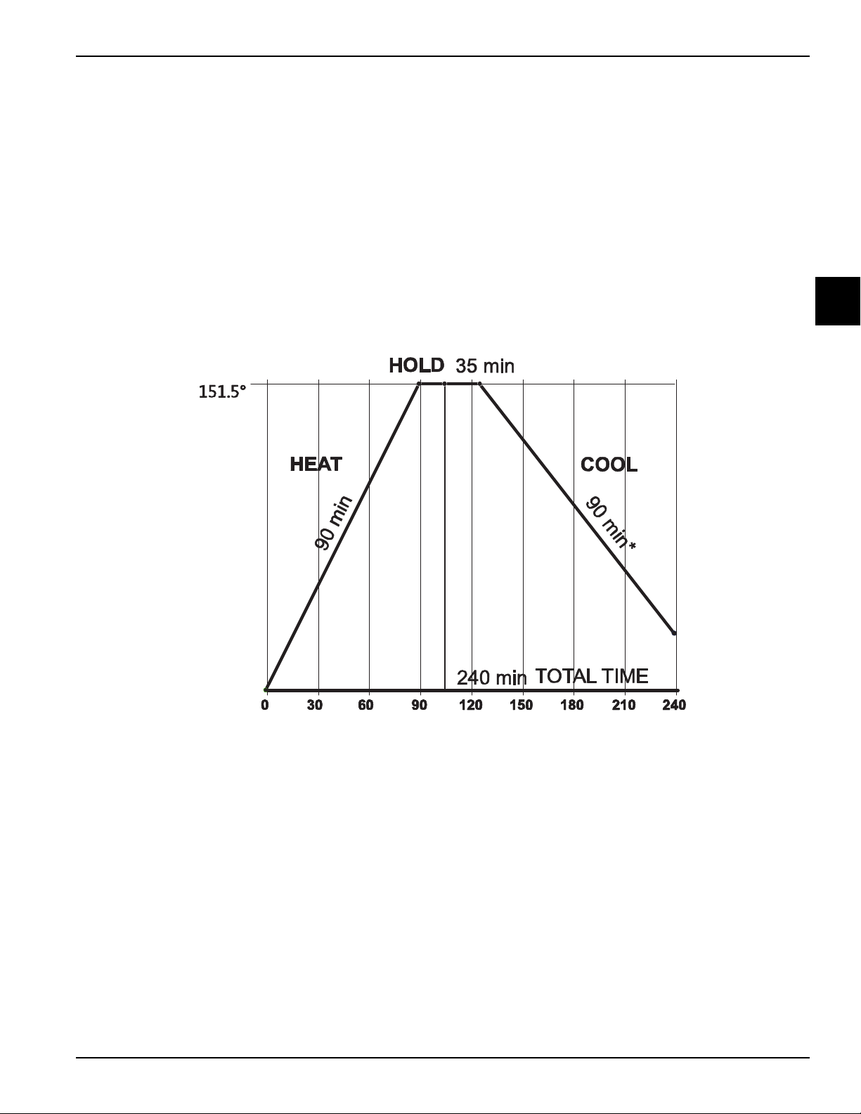
Heat Treatment Graph
CONTROLS
The purpose of the heat phase is to raise the product
temperature above 150°F (65°C) within 90 minutes. To
satisfy the control system, the product must actually
reach 160°F (71°C) in the freezing cylinder and 155°F
(68°C) in the hopper. This requirement ensures that the
150°F (65°C) requirement has been met. Health laws
require these parameters to be 150°F (65°C) in
90 minutes; however, the actual amount of time the
freezer takes to accomplish this requirement is closer to
60 minutes.
While in the cool phase, the hopper and freezing cylinder
are maintained at standby temperatures.
Note: To accommodate agitator mode operation (with
hopper refrigeration), the hopper and standby
temperature setpoint maximum and default values are
lowered from 39°F to 37°F (3.9°C to 2.8°C).
The cool phase concludes when the hopper and freezing
cylinder reach 41°F (5°C). At this point the machine
enters Standby mode. While the time given for the cool
phase is 90 minutes for UVC3 machines and 120
minutes for UVC4 machines, the actual time is closer to
30 minutes.
2
Figure 2-3
Note: The maximum allowable cool phase for UVC4 machines is 120 minutes.
Controls
Models C708/C709/C716/C717
2-19
Page 46

CONTROLS
BRUSH CLEAN TIMEOUT
FREEZER LOCKED
CLEANING REQ’D
> BRUSH CLEAN
FREEZER LOCKED
SYSTEM FAULT
FREEZER LOCKED
SERVICE REQ’D
> BRUSH CLEAN
HOPPER THERM BAD
FREEZER LOCKED
BARREL THERM BAD
FREEZER LOCKED
FREEZER LOCKED
Freezer Lock-Out
To comply with health codes, heat treatment system
freezers must complete a Heat Treatment Cycle daily,
and must be disassembled and brush cleaned a
minimum of every 14 days.
Important! Always comply with local guidelines for the
maximum number of days allowed between brush clean
cycles. (See the Manager's Menu for setting the Brush
Clean interval.)
Brush cleaning is the normal disassembly and cleaning
2
procedure found in the Operator’s Manual. Failure to
follow these guidelines will cause the control to lock the
freezer out of the Auto mode.
If the Heat Treatment Cycle fails, the screen will display a
failure message and return the freezer to the Standby
mode.
There are two types of freezer lock conditions that can
occur: hard lock or soft lock. A hard lock requires the
machine be disassembled and brush cleaned. A soft lock
can be corrected by either disassembling and brush
cleaning the machine, or by starting another Heat
Treatment Cycle.
Thermistor Failure
The following screen is displayed if there has been a
thermistor failure (freezing cylinder or hopper) during the
heat treatment process:
Pressing the SEL button will indicate which thermistor
caused the hard lock.
Hard Lock
There are two causes of a hard lock failure. The freezer
will hard lock if either the Brush Clean Timer has elapsed
or if a thermistor failure (freezing cylinder or hopper)
occurred during a Heat cycle.
Brush Clean Timeout
The following screen will be displayed if a brush clean
cycle timeout has occurred:
Pressing the SEL button displays the following screen:
2-20
Note: Three codes have been set up to assist in
diagnosing bad thermistor probes. If a probe has shorted
(resistance less than 1 ohm), SHRT is displayed on the
screen for its respective machine location. If the probe is
open (resistance above 1 megohm), OPEN is displayed.
If the actual probe environment exceeds 200 °F (93°C),
the respective screen display location will read OVER
indicating the temperature is out of range.
If the machine has hard locked and an attempt is made to
enter Auto mode, the machine will enter the Standby
mode and display the following message.
To restore the message that identified the reason for the
hard lock, turn the power switch OFF for 5 seconds and
then return the power switch to the ON position. The
original message with the reason for the hard lock will be
displayed.
Models C708/C709/C716/C717
Controls
Page 47

CONTROLS
NO HEAT CYCLE START
REASON
> HEAT CYCLE
BRUSH CLEAN
HEAT TREAT FAILURE
FREEZER LOCKED
> HEAT CYCLE
BRUSH CLEAN
PRODUCT OVER TEMP
> HEAT CYCLE
BRUSH CLEAN
DO NOT DRAW
The FREEZER LOCKED message remains on the
display until the brush clean requirements are fulfilled.
The freezer must be disassembled in order to activate
the 5-minute timer on the display screen. Once the timer
counts down to zero, the lockout is cleared.
Soft Lock
If a Heat Treatment Cycle has not been initiated within
the last 24 hours, a soft lock failure will occur. A soft lock
allows the operator to correct the cause of the soft lock.
The operator has the option of either starting another
heat cycle or brush cleaning the machine. When a soft
lock occurs, the machine will go into the Standby mode.
The following message is displayed on the screen. The
reason for the soft lock is indicated on the second line.
If the following screen appears, a soft lock has occurred
during the heat treatment cycle.
A soft lock can also occur any time during operation
when the hopper or freezing cylinder temperature rises
above 59°F (15°C), the temperature rises and remains
above 45°F (7°C) for more than 1 hour, or the
temperature rises and remains above 41°F (5°C) for
more than 4 hours.
If a product over temperature condition occurs during
operation, the following screen will appear.
2
If the reason for the soft lock has been corrected,
selecting HEAT CYCLE initiates a heat cycle
immediately. Selecting BRUSH CLEAN when the
previous message is displayed will hard lock the machine
and brush cleaning will be necessary.
Following are the variable messages for soft lock failures
that appear on the second line of the screen.
POWER SWITCH OFF Power switch was in the OFF
position.
MIX-OUT PRESENT There was a Mix-Out condition
present.
AUTO OR STANDBY
OFF
NO HEAT CYCLE
TRIED
The machine was not in the Auto or
Standby mode.
A heat treatment cycle was not
attempted in the last 24 hours.
(AUTO HEAT TIME was advanced or
a power loss was experienced at the
time the cycle was to occur.)
Additional faults which will result in a soft lock condition if
they occur during a Heat Treatment Cycle are listed
below, along with an explanation of the corrective action.
• BEATER OVERLOAD—Place the power switch
in the OFF position. Press the beater reset
button firmly. Place the power switch in the ON
position and restart in Auto mode.
• COMP ON TOO LONG—The compressor run
time exceeded the 11-minute timer. Make sure
the beater rotation is clockwise. Check the
scraper blades and the refrigeration system.
When a soft lock condition has occurred, automatic
freezer operation cannot take place until the freezer is
disassembled and brush cleaned, or has completed a
Heat Treatment Cycle.
Once the freezer is unlocked by starting a Heat
Treatment Cycle, the Heat Cycle button will illuminate
and the following message is displayed on the screen.
Controls
Models C708/C709/C716/C717
2-21
Page 48

CONTROLS
FREEZER LOCKED
HEAT TREAT FAILURE
REASON
> HEAT CYCLE
BRUSH CLEAN
If BRUSH CLEAN is selected to clear the lockout by
brush cleaning the machine, the FREEZER LOCKED
message will remain on the display until the brush clean
requirements are fulfilled. The freezer must be
disassembled in order to activate the 5-minute timer on
the display screen. Once the timer counts down to zero,
the lockout is cleared.
2
To restore the message that identified the reason for the
soft lock, turn the power switch OFF for 5 seconds, and
then return the power switch to the ON position. The
original message with the reason for the soft lock is
displayed.
A record of Heat Cycle Data and Lock Out History can be
found in the Manager's Menu.
2-22
Models C708/C709/C716/C717
Controls
Page 49

Power Interrupt
POWER SWITCH OFF
TIME: 5:00
HOPPER 41.0
BARREL 41.0
POWER SWITCH OFF
Ŧ = Ŧ = Ŧ = Ŧ = Ŧ = Ŧ
UNIT CLEANED
UNIT CLEANED
CONTROLS
All operating modes and setpoints are stored in the
battery-backed memory. Having been in the Auto,
Standby, or any of the Heat mode phases, recovery from
a power failure will return the machine to its previous
mode of operation after a Memory Initialization function
has occurred. If a power failure has occurred, the
SAFETY TIME OUT screen will display a Power Failure
message on the first line and the audio alarm will be on.
This message must be cleared.
If the freezing cylinder or hopper temperature rises above
41°F (5°C) and stays above 41°F (5°C) for 4 hours, the
machine will soft lock when power is restored. If the
temperature rises above 59°F (15°C) the machine will
lock immediately.
14 Day Brush Clean
For the control to recognize that the machine has been
brush cleaned, the following criteria must be met.
1. The freezing cylinder and hopper temperatures must
be above 60°F (16°C).
2. The Mix-Out and Mix-Low probes must not be
satisfied.
A screen showing the status of the elements required for
a brush clean are displayed when the power switch is in
the OFF position and the machine is not in a brush clean
state.
Line 1: Indicates the power switch is OFF.
Line 2: Shows the time (in minutes and seconds)
remaining for the system to enter a Brush Clean state.
Line 3: Shows the hopper temperature.
Line 4: Shows the barrel temperature.
If any of the requirements for a brush clean have not
been met, the time displayed will remain at 5:00 minutes.
When all the requirements for a brush cleaning are met,
and the 5 minutes expire, the screen will change to the
second screen, which is the standard POWER SWITCH
OFF screen.
2
3. The door must be removed.
Note: The power switch must be OFF to view the
5 minute countdown timer.
Note: The criteria in Steps 1 to 3 must be met
simultaneously for 5 minutes. These criteria are met
when the machine is properly brush cleaned according to
the Taylor Operator's Manual.
Completion of a successful brush clean resets the Brush
Clean Cycle timer and removes the locked condition. A
new brush clean date is calculated the first time that the
Auto or Standby mode is entered.
When the power switch is placed in the ON position, the
third line of the screen displays UNIT CLEANED.
Controls
Models C708/C709/C716/C717
2-23
Page 50

CONTROLS
1
6
7
8
3
2
4
5
Pump Operation
Pump Button
When the Pump button is pressed, the pump is active by
itself or with the Wash mode of operation.
Mix Pump
The mix pump will be active for 30 seconds whenever the
Auto mode is entered. If a Mix-Out condition forces the
2
machine into the Standby mode of operation, the mix
pump will not be active.
Mix Pump Draw Timer
During the Auto mode, the mix pump will operate for
5 to 30 seconds after every draw of product. The factory
setting is 10 seconds.
Item Description Part No.
1 Screw-1/4-20X-3/4 Socket 020128-2
2 Motor-Reducer 32 RPM 036955-34
3 Mount-Motor 036934
4 Sleeve A.-Mix Pump X44761
2-24
Models C708/C709/C716/C717
Figure 2-4
Item Description Part No.
5 Coupling-Motor-Flexible 047936
6 Seal-Motor Reducer Input 048836
7 Seal-Motor Reducer-Out 048837
8 Nut-Pump Sleeve 036933
Controls
Page 51

Timers
CONTROLS
Stir Cycle Timer
Standby Mode
When the standby temperature setpoint is satisfied, the
beater motor activates for 6 seconds every 2 minutes if
the stir cycle jumper (W3) is not installed.
If the stir cycle jumper (W3) is installed, the beater motor
activates for 6 seconds every 6 minutes.
Note: When the 6-minute stir cycle is selected, the
standby barrel temperatures are automatically set to
30°F (-1.1°C) and cannot be adjusted.
Auto Mode
The stir cycle time corresponds with the compressor
cycle time. If the compressor cycle time is 5 minutes, the
stir cycle will be 5 minutes. If the barrel viscosity is below
setpoint, the beater motor and compressor continue to
run until the viscosity setpoint is reached.
Heat Mode (Heat Cycle)
The beater motor continues the 2-minute stir cycle until
the freezing cylinder temperature rises above 100°F
(38°C). Once this temperature is reached, the beater
motor runs continuously.
Manual Clean Indicator
The two-digit LED display in the user interface displays
the number of days until the next required manual brush
cleaning.
24 Hour Last Heat Cycle Event
If the machine runs longer than 24 hours without a
successful Heat Treatment Cycle, the machine will soft
lock.
Brush Clean Cycle Timer
If the machine runs longer than the programmed number
of days (2 to 14) without a successful brush cleaning, the
machine will hard lock.
Heat Phase Timer
The heat phase timer times out the maximum allowable
time the machine can be in the heat phase of the Heat
Treatment Cycle (90 minutes). If the timer exceeds
90 minutes, the machine will lock out.
2
Heat Mode (Cool Cycle)
The barrel must satisfy the standby temperature setpoint.
If the setpoint is satisfied, the beater motor will activate
6 seconds every 2 minutes. The beater motor and
compressor will activate if the barrel temperature rises
above the standby temperature setpoint.
Mix Pump Timer
Mix pump operation is determined by the selection made
in the Mix Pump Off Delay menu item.
If Standard is selected, the mix pump runs for
30 seconds when entering Auto mode. It also runs as
long as the draw switch is active and continues for the
time programmed in the Mix Pump Off Delay menu.
If Barrel Refrig is selected, the mix pump runs for 30
seconds when entering Auto mode. It also runs as long
as the draw switch is active and continues for the time
programmed in the Mix Pump Off Delay menu. Each time
the barrel begins refrigeration, the mix pump runs the
amount of time programmed in the Mix Pump Off Delay
and then stops.
Hold Phase Timer
This timer assures that product in the freezing cylinder
and the hopper are held above 150°F (65°C) for a
minimum of 35 continuous minutes for UVC3 machines
and 30 continuous minutes for UVC4 machines.
Cool Phase Timer
The cool phase timer times out the maximum allowable
time the machine can remain in the cool phase of the
heat treatment cycle (90 minutes). If the timer exceeds
90 minutes, the machine will soft lock.
Heat Cycle Total Time Timer
The heat cycle TT timer times out the maximum
allowable time the machine can be in the heat cycle,
which is 6 hours. If the timer exceeds 6 hours, the
machine locks.
Controls
Models C708/C709/C716/C717
2-25
Page 52

CONTROLS
Safety Timeout
Once power is applied to the machine, a 60-second timer
places the machine in an Idle state. The tone is turned on
in 1-second intervals, and a Safety Timeout message
appears on the LCD. This timer can be aborted by
pressing any button.
Compressor On Timer
The compressor run time is monitored while the barrel
temperature is below 41°F (5°C). The timer is disabled if
2
product in barrel is above 41°F (5°C), if compressor is not
running, or if draw switch is on. In Auto mode, when 11
minutes is counted down, a fault is generated and stored
in Fault History, and the compressor is turned off. The
compressor starts again with the next compressor cycle
time or with the draw switch. Whenever the draw switch
is on, the compressor on timer is reset to 11 minutes. In
Standby mode, when 11 minutes is counted down, if the
product in the barrel is above the standby temperature
37°F (5°C) default) a fault generates, tone sounds, and
compressor turns off. The compressor starts again with
the next stir cycle.
Brush Clean Timer
This timer times out in 5 minutes when all conditions for a
successful brush cleaning are met.
Barrel Hot Gas Solenoid Timer
This timer opens if the barrel temperature is below the
barrel heat temp setpoint of 28°F (-2° C). This operation
is disabled during the first 10 minutes of the heat cycle.
Compressor Rest
A 120-second compressor rest keeps the compressor
from activating after shutting off for 120 seconds, unless
a draw event occurs. If a draw event occurs, the
compressor starts regardless of the time of last
activation.
2-26
Models C708/C709/C716/C717
Controls
Page 53
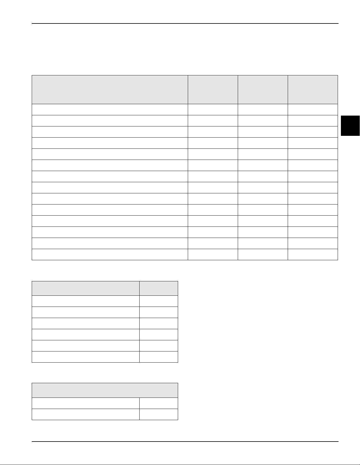
Jumper Pin Charts
Jumper Chart—UVC3
CONTROLS
Table 2-1
C708/C709
Feature
Force Brush Clean Status W2 W2
Syrup Heater Enable W3
Open All Left Solenoids W4 W4
Open All Right Solenoids W4
Clock/Calendar Override W5 W5
Force Glycol Pump On
59F Fault Detection Enable J10 - 1 and 2 W2**
Standby Stir Cycle Disable W3 W5
Reduced Mix-Low Sensitivity W6 W6
Reduced Mix-Out Sensitivity W7 W7
7°C/45°F 90 Min. Cool Phase
Unused W1 W1
Unused W3
Left Interface
X58482-SER
C716/C717
Left Interface
X59485-SER
Right Interface
C716/C717
X59485-SER
2
Disable Control Panel (Self Serve) J10 - 7 and 8 J10 - 7 and 8
**Jumper initially installed at factory.
Table 2-2
UVC3 Control Feature Jumper
Note:
1. Left and right are determined while facing the front of
machine.
>41°F for 4 hours and >45°F for 1 hr JP1 - 1 and 2**
Reserved (do not install) JP1 - 3 and 4
Domestic/International (See note 3) JP2 - 1 and 2 **
Reserved (do not install) JP2 - 3 and 4
2. Specified feature is established when the jumper is
installed.
3. International mode (jumper removed) enables direct
use of Heat Cycle and Standby buttons and hopper
temperature display.
Audible enable (do not install) JP3 - 1 and 2
Unused JP3 - 3 and 4
**Jumper initially installed at factory.
Table 2-3
Personality Board
0–6 Beater Motor Amperage (do not use) A
0–12 Beater Motor Amperage B**
**Jumper initially installed at factory.
Controls
Models C708/C709/C716/C717
2-27
Page 54

CONTROLS
Jumper Chart—UVC4
Table 2-4
C708/C709
Feature
Force Brush Clean Status W2 W2
Syrup Heater Enable W3
Open All Left Solenoids W4 W4
Open All Right Solenoids W4
2
Clock/Calendar Override W5 W5
Force Glycol Pump On
59°F Fault Detection Enable J10 - 1 and 2 W2**
Standby Stir Cycle Disable W3 W5
Reduced Mix-Low Sensitivity W6 W6
Reduced Mix-Out Sensitivity W7 W7
7°C/45°F 90 Min. Cool Phase
Unused W1 W1
Unused
Left Interface
X58482-SER
C716/C717
Left Interface
X59485-SER
C716/C717
Right Interface
X59485-SER
Disable Control Panel (Self Serve) J10 - 7 and 8 J10 - 7 and 8
**Jumper initially installed at factory.
Table 2-5
UVC4 Control Feature Jumper
>41°F for 4 hours and >45°F for 1 hr JP1 - 1 and 2**
Reserved (do not install) JP1 - 3 and 4
Domestic/International (See Note 3) JP2 - 1 and 2 **
Reserved (do not install) JP3 - 1 and 2
Reserved (do not install) JP4 - 1 and 2
0–6 Beater Motor Amperage (do not use) A
0–12 Beater Motor Amperage B**
**Jumper initially installed at factory.
Note:
1. Left and right are determined while facing the front of
Table 2-6
Personality Board
machine.
Proximity Sensor (See Note 4) JP5 - 1 and 2**
2. Specified feature is established when the jumper is
Reserved (do not install) JP6 - 1 and 2
Reserved (do not install) JP7 - 1 and 2
Reserved (do not install) RTCK - 1 and 2
Reserved (do not install) DBGEN - 1 and
2
**Jumper initially installed at factory.
installed.
3. International mode (jumper removed) enables direct
use of Heat Cycle and Standby buttons and hopper
temperature display.
4. Jumper should be installed on shake machines to
enable proximity sensor. It is not active on soft serve
machines; jumper can remain installed.
2-28
Models C708/C709/C716/C717
Controls
Page 55

Beater Stir Cycles
CONTROLS
Standby
When the machine is in the Standby mode, the stir cycle
will be activated. The beater stir cycle timer counts down
2 minutes (in seconds) and then activates the beater
motor for 6 seconds. After the stir cycle, the process
repeats; the timer counts down 2 minutes, and the beater
runs for 6 seconds.
Hopper Temperature
To accommodate agitator mode (with Hopper Refrig)
operation, the hopper and standby temperature setpoint
maximum and default values are lowered from 39°F to
37°F (3.9°C to 2.8°C). In the Auto or Standby mode, the
compressor starts when the hopper temperature is above
the setpoint and stops when the hopper temperature
reaches the setpoint 28°F (-2°C).
The hopper liquid solenoid opens when the hopper
temperature rises above this setpoint and closes when
the hopper temperature is below its setpoint 28°F (-2°C).
2
Controls
Models C708/C709/C716/C717
2-29
Page 56

CONTROLS
VISCOSITY SETTING
VISC = 2.8 AMPS
CURRENT = 0.0
Setting Viscosity
Viscosity
Viscosity is the term used when referring to product
appearance, temperature, thickness, and firmness.
Soft serve viscosity is measured by monitoring the
amperage load of the beater motor. The amperage load
of the beater motor is low when the product in the
freezing cylinder is liquid. As the product freezes
(thickens), the amperage load increases. When the
2
amperage load reaches the setpoint, the refrigeration
cycle discontinues.
The factory setting (setpoint) for soft serve viscosity is
2.8 amps. The amperage measurement is determined by
monitoring the L1 leg of power being delivered to the
beater motor. To adjust the serving viscosity, it may be
necessary to raise or lower the amperage setpoint.
Adjust in increases of 0.1 amps.
The serving temperature of soft serve product may vary
throughout the day. The serving temperature may range
from 16°F to 19°F (-8.8°C to -7.2°C).
Figure 2-5
2-30
Models C708/C709/C716/C717
Controls
Page 57

C708/C709 Control Overview
UVC3
CONTROLS
2
Controls
Figure 2-6
Models C708/C709/C716/C717
2-31
Page 58

CONTROLS
C708/C709 Control Overview – UVC4
2
2-32
Figure 2-7
Models C708/C709/C716/C717
Controls
Page 59
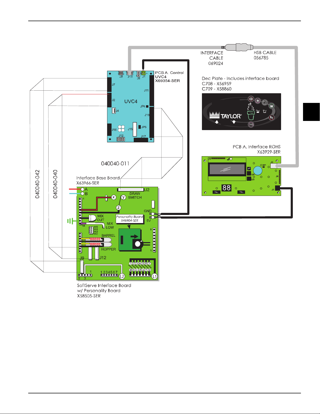
C708/C709 Control Overview – UVC4 Field Updated
CONTROLS
2
Controls
Figure 2-8
Models C708/C709/C716/C717
2-33
Page 60

CONTROLS
C716/C717 Control Overview
UVC3
2
2-34
Figure 2-9
Models C708/C709/C716/C717
Controls
Page 61

C716/C717 Control Overview—UVC4
CONTROLS
2
Controls
Figure 2-10
Models C708/C709/C716/C717
2-35
Page 62
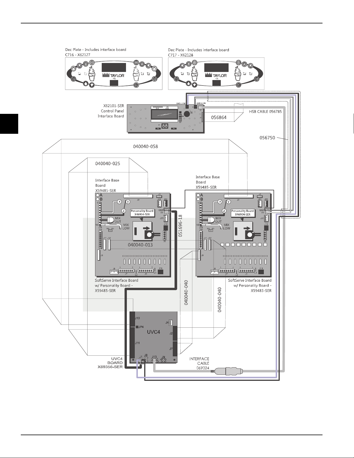
CONTROLS
C716/C717 Control Overview—UVC4 Field Updated
2
2-36
Figure 2-11
Models C708/C709/C716/C717
Controls
Page 63

Universal Control Board
1
9
8
7
6
5
4
3
2
Universal Control Board Connections—UVC3
CONTROLS
2
Item Description Function
1 5 VDC Power Supply Supplies power to UVC3 Board (Range: 4.75 - 5.25 VDC)
2 LED When board is powered, LED flashes On (0.5 sec.) and Off (0.5 sec.)
3 RAM Chip Stores program settings from menu in memory
4 EPROM Chip PLCC Chip Software Version Number
5 JP1 Pins See table on page 2-28
6 JP3 Pins See table on page 2-28
7 Audible Tone Device See table on page 2-28
8 JP2 Pins See table on page 2-28
9 USB Cable Connection Communication to control panel interface board
Figure 2-12
Controls
Models C708/C709/C716/C717
2-37
Page 64

CONTROLS
4
3
2
1
9
8
7
6
5
Universal Control Board Connections—UVC4
Beginning in January 2011, Taylor started transitioning
from the UVC3 to the UVC4.
2
Note: UVC4 can only be used to replace UVC3 boards.
UVC4 is not compatible with UVC1 or UVC2.
The following chart identifies the connections on the board:
Table 2-7
Item Jumper No. Function
1 J1 5 VDC power input
2 J11 50 pin digital cable-right side
3 J10 50 pin digital cable-left side
4 J12 Local On-site Network (LON) cable
5 D2 Heartbeat LED
Figure 2-13
Important: See “UVC4 Electrostatic Discharge and Proper
Handling Procedures” on page 2-39 before handling a UVC4
board.
Item Jumper No. Function
6 J4 USB program port
7 J2 18 pin power loss analog cable
8 J7 18 pin amp draw and thermistor
probe data analog cable
9 J13 User interface cable
2-38
Models C708/C709/C716/C717
Controls
Page 65

CONTROLS
Universal Control
The Universal Control is the command center for the
machine. The software program for the UVC3 control,
including multiple language selections, resides in the
erasable programmable read-only memory (EPROM)
chip. The EPROM chip is not used on the UVC4
Universal Control.
The settings in the menus are saved in the random
access memory (RAM) chip. Removing and reinstalling
the RAM chip restores the factory default settings in the
menus. The RAM chip must be inserted with the notch
towards the side of the socket with the notch.
Power is supplied to the 5 VDC terminal on the UVC3/
UVC4 board from the interface board. The operating
voltage range for the control is 4.75VDC to 5.25VDC.
Note: Beginning with software version 1.07, the default
settings can be restored in the Service Menu. This can
only be done when the machine is in a Unit Cleaned
State. The machine must be cleaned or the W-2 on the
shake side interface board must be jumped out to enter a
Unit Cleaned State. (See “Reset to Defaults” on page
2-17.)
Note: For installations with low voltage supply (210V or
less) it may be necessary to wire the 16 VAC transformer
on the low voltage tap. Low voltage supplied to the
interface board, in turn reduces the voltage supplied to
the UVC3/UVC4 board and may cause intermittent power
failure tripping or the control panel keys do not function
when the machine is powered.
The UVC3/UVC4 communicates with the control panel
interface board through a USB Cable.
There are three sets of pins on the UVC3 board and four
sets of pins on the UVC4 board. Refer to the following
chart to identify their function.
Note: Use Part No. 040084-001
Connector-Programing Shunt to jumper pins.
Starting Serial Numbers Built With UVC4
C708/C709 M1084626 X69354-SER
C716/C717 M1066352 X69356-SER
UVC3 to UVC4 Conversion Kit Part Numbers
C708/C709 X69354-SER1
C716/C717 X69356SER1
UVC4 Electrostatic Discharge and Proper Handling
Procedures
The UVC4 board is more susceptible to electrostatic
discharge than the UVC3 board. Always use the
following procedures to prevent damage when handling
the board.
1. Leave boards in their anti-static packaging until they
are ready to be installed.
2. Dissipate static electricity before handling the board
by touching a grounded metal object, such as the
machine's unpainted metal chassis.
3. If possible, use anti-static devices such as wrist
straps and floor mats.
4. Always hold the board by its edges. Avoid touching
the contacts and components on the board.
5. Take care when connecting or disconnecting cables.
A damaged cable can cause a short in the electrical
circuit.
6. Prevent damage to the connectors by aligning the
connector pins before connecting the cable.
Misaligned connector pins can cause damage to
components at power-on.
7. When disconnecting a cable, always pull on the cable
connector or strain-relief loop, not on the cable itself.
2
Controls
Models C708/C709/C716/C717
2-39
Page 66

CONTROLS
UVC4 Cables – Factory Installed
2
Figure 2-14
Boards installed at the factory have two cables
connected to the UVC4 board. Connected at J13 is the
USB cable part number 069023.
2-40
Models C708/C709/C716/C717
Important! See “UVC4 Electrostatic Discharge and
Proper Handling Procedures” on page 2-39 before
handling a UVC4 board.
Controls
Page 67
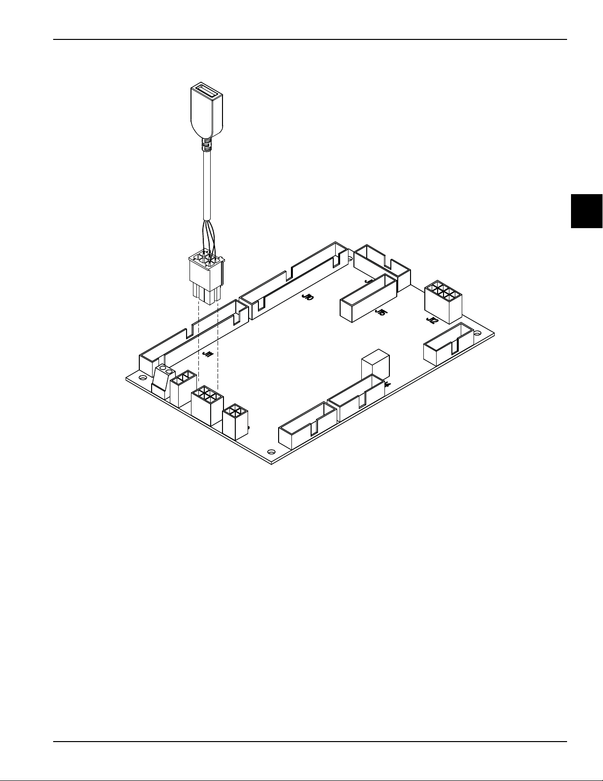
UVC4 Cables – Conversion Kit For Field Replacements
CONTROLS
2
Figure 2-15
The UVC4 board is interchangeable with the UVC3
board. When replacing a UVC3 board in the field, adapter
cables are needed. Cable part number 069024 (1)
connects to the existing USB cable.
Controls
Models C708/C709/C716/C717
Important! See “UVC4 Electrostatic Discharge and
Proper Handling Procedures” on page 2-39 before
handling a UVC4 board.
2-41
Page 68

CONTROLS
C708/C709 UVC4 Update Instructions
Estimated Time: 35 minutes
Important!
• See “UVC4 Electrostatic Discharge and Proper
Handling Procedures” on page 2-39 before
handling a UVC4 board.
• Before performing the software update, reset
the control to defaults. This will clear the RAM
memory so the new software can be loaded.
• Only use factory supplied USB drives to perform
2
1. Enter the Service menu (5231) to copy the current
2. Place the machine in the Off mode and turn the syrup
software update. Do not make copies of factory
supplied USB drives with generic USB drives.
Failure to follow this instruction can cause
issues in successfully completing the software
update.
• Wear appropriate personal protective
equipment.
machine settings.
heaters off.
12. Check jumper position JP7. Remove the jumper, if
present, and do not re-install.
13. Access the Service Menu. Go to Software Update
and select Yes to begin Update process.
14. Wait 3 minutes for the software to complete the
update.
15. After the Lamp Test enter the Service Menu and clear
any faults. Reset machine to defaults.
16. Re-enter all settings copied earlier.
17. Remove the USB flash drive from the UVC4 board
and store it in the tool kit.
18. Place the machine in the Auto mode. Turn the syrup
heaters back on, if that was the original state before
the installation.
19. Verify the machine is operating properly (shutting off
at proper viscosity and no faults).
20. Draw at least one soft serve cone to verify that the
product appearance is acceptable.
21. Carefully reinstall the control box cover, side panel,
and drip tray.
WARNING! Always disconnect electrical
power prior to cleaning the condenser. Failure to follow
this instruction may result in electrocution.
3. Remove the drip tray from the left side of the
machine and place it on top of the machine.
4. Remove the 4 screws from Panel-Side-Left C708,
C709 (056963).
5. Remove the 4 screws from the Cover-Control Box
C708, C709 (056929).
6. Install a jumper on the W2 on the interface board.
7. Reconnect power to the machine and turn the power
on. Verify that the display says UNIT CLEANED.
8. Remove the jumper from W2 on the interface board.
9. Enter the Service menu and go to the option, Reset
to Defaults.
10. Perform a Reset to Defaults by selecting YES to
clear all RAM memory.
11. Install the USB flash drive in the J4 port on the UVC4
board.
C716/C717 UVC4 Update Instructions
Estimated Time: 35 minutes
Important!
• See “UVC4 Electrostatic Discharge and Proper
Handling Procedures” on page 2-39 before
handling a UVC4 board.
• Before performing software update, reset the
control to defaults. This will clear the RAM
memory so the new software can be loaded.
• Only use factory supplied USB drives to perform
software update. Do not make copies of factory
supplied USB drives with generic USB drives.
Failure to follow this instruction can cause
issues in successfully completing the software
update.
• Wear appropriate personal protective
equipment.
1. Enter the Service Menu (5231) to copy the current
machine settings.
2. Place both sides of the machine in the Off mode and
turn the syrup heaters off.
2-42
Models C708/C709/C716/C717
Controls
Page 69

CONTROLS
12. Check jumper position JP7. Remove the jumper, if
present, and do not reinstall.
WARNING! Always disconnect electrical
power prior to cleaning the condenser. Failure to follow
this instruction may result in electrocution.
3. Remove the two drip trays from the upper rear of the
machine and place them on top of the machine.
4. Remove the two screws at the bottom of the
Panel-Rear-Upper C716, C717 (064258).
5. Remove the six screws from the Cover-Control Box
C16, C717 (067984).
6. Install a jumper on the W2 on the left side interface
board.
7. Reconnect power to the machine and turn power on.
Verify that the display says UNIT CLEANED.
8. Remove the jumper from W2 on the left side interface
board.
9. Enter the Service menu and go to the option, Reset
to Defaults.
10. Perform a Reset to Defaults by selecting Yes to clear
all RAM memory.
13. Access the Service Menu. Go to Software Update
and select Yes to begin update process.
14. Wait 3 minutes for the software to complete the
update.
15. After the lamp test, enter the Service Menu and clear
any faults. Reset machine to defaults.
16. Re-enter all settings copied earlier.
17. Remove the USB flash drive from the UVC4 board
and store it in the tool kit.
18. Place both sides of the machine in the Auto mode.
Turn the syrup heaters back on, if that was the
original state before the installation.
19. Verify both sides of the machine are operating
properly (shutting off at proper viscosity and no
faults).
20. Draw at least one soft serve cone per side to verify
that the product appearance is acceptable.
21. Carefully reinstall the control box cover, back panel,
and drip trays.
2
11. Install the USB flash drive in the J4 port on the UVC4
board.
Controls
Models C708/C709/C716/C717
2-43
Page 70

CONTROLS
Refrigeration System—Hot Gas Treatment
The refrigeration system utilizes a main compressor that
provides heating and cooling for the freezing cylinder and
the hopper. An AXV expansion valve is used on the
freezing cylinder to provide consistent product quality by
maintaining the evaporating temperature at
-15°F (-26°C).
A capillary tube on the hopper system for the cool phase
provides the required control of refrigerant mass flow to
control refrigerant floodback to the compressor.
2
There is a provision for liquid refrigerant injection to the
compressor suction to control excessive compressor
discharge temperature during the cool phase. The bulb is
located on the discharge line near the compressor to
sense when the discharge temperature approaches
250°F (121°C).
Note: The valve opens at 230°F (110°C).
There are two liquid line solenoid valves to provide
control over the refrigeration to the hopper and freezing
cylinder during the cool phase. Both liquid line solenoids
are closed during the hot gas heat phase.
Two hot gas solenoid valves are used during the heat
phase to direct the compressor discharge gas to the
freezing cylinder and hopper, bypassing the condenser,
freezing cylinder AXV and the hopper capillary tube.
When only the hopper is being cooled, a hot gas bypass
valve is used to divert refrigerant gas to the suction line.
In order to maintain product temperature above 150°F
(65.5°C) for 35 minutes during the hold phase, the
compressor will cycle on and off.
The main system condenser is a 3-row 5/16 in. tube and
raised lance fin condenser. The liquid line receiver helps
control the variable amount of free refrigerant in the
system. A filter dryer is provided. There is a liquid
line - suction line heat exchanger on the main
refrigeration system.
Note: This information applies to both sides on the
C716 and C717 - independent systems.
2-44
Models C708/C709/C716/C717
Controls
Page 71

Checking and Setting Refrigeration Valves
CONTROLS
All Machines
This machine is equipped with a safety door lock.
Freezer operation is not allowed in the Auto, Standby, or
Wash modes if the door is off. In order to perform a frost
check or a beater rotation check, the technician must use
a magnet to bypass the reed switch located behind the
front panel.
Note: To check various pressures in the refrigeration
system, the machine must be assembled and have
product in both the hopper and the freezing cylinder.
Gauges should not be installed on these freezers unless
a problem is suspected with the refrigeration system.
Once you have determined there is a problem, perform
the following procedures:
1. Install refrigeration gauges on the service valves
located behind the lower front panel. Remove the
safety cover for complete access.
2. Install a suction line gauge on the Schrader valve
fitting on the EPR valve. (See the refrigeration
schematic.)
4. When the compressor has cycled off, place the
machine in Auto mode. Set the freezing cylinder
expansion valve to 20 psi to 22 psi (138 kPa to 145
kPa) and the water valve to 255 psi (1,758 kPa) if so
equipped.
5. Place the freezer into a Heat Cycle. The hopper only
will heat for the first 10 minutes and then the freezing
cylinder will begin to heat.
6. Once the hopper and freezing cylinder are above
100°F (38°C), set the OPR valve to 21 psi (145 kPa)
by reading the pressures at the service valves.
Failure to follow these procedures will result in
improperly set valves and poor freezer performance.
To reclaim and recharge a system, install a jumper
on W4 on the interface board to open all solenoids.
Remove the jumper upon completion of the recharge
and check valve settings as outlined above.
Note: Each side must be set individually on the C716
and C717.
2
3. Place the freezer in the Standby mode. When the
freezing cylinder is satisfied and the hopper only is
cooling, adjust the evaporator pressure regulator
(EPR) valve to 60 psi (414 kPa) by reading the
suction gauge on the EPR access fitting.
Note: The coarse adjustment of the EPR valve can be
made starting immediately after the hopper only is still
cooling. It gets easier to make the final adjustments when
the hopper gets closer to the cycle off temperature. After
the coarse adjustment is made, observe, and make the
final adjustment when the temperature reaches 37°F
(2.8°C).
Controls
Models C708/C709/C716/C717
2-45
Page 72
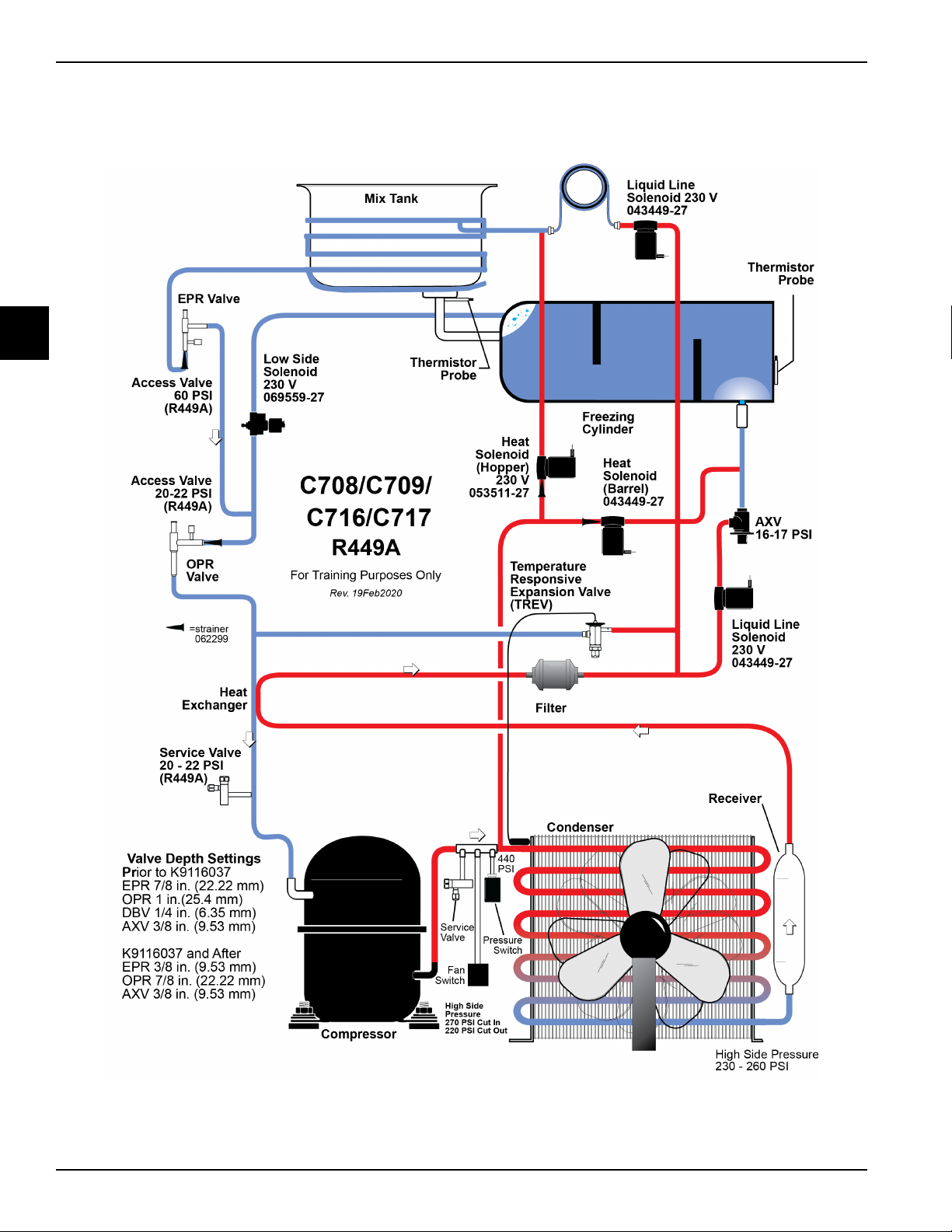
CONTROLS
Refrigeration Schematic
2
Figure 2-16
Note: Refrigeration diagram shows only one side of the Models C716 and C717.
2-46
Models C708/C709/C716/C717
Controls
Page 73

Refrigeration System Components
Table 2-8
Name Description
Mix Hopper 20 qt. capacity, wrapped with 40 ft. of 5/16 in. copper tubing
Freezing Cylinder Conventional, 3.4 qt. (3.2 L) flooded evaporator
Condenser Lanced fin
Fans-Condenser Motor A.-Fan 185 W 1400 RP
CONTROLS
Compressor Bristol (see Parts Update #196)
AXV Automatic expansion valve for the freezing cylinder
TXV Thermo controlled expansion valve for the mix hopper / Replaced w/Tube-
capillary S/N M603657
SV01 Barrel liquid solenoid valve
SV02 Hopper liquid solenoid valve
SV03 Barrel hot gas solenoid valve
SV04 Hopper hot gas solenoid valve
SV05 Barrel suction solenoid valve
SV06 Discharge bypass line solenoid valve
EPR Alco, IPR-6, Inlet Pressure Upstream Regulator
OPR Alco, OPR-10, Outlet Pressure Downstream Regulator
TREV Temperature Responsive Expansion Valve
Filter/Dryer Dryer-Filter-HP62-3/8 x 1/4S
Heat Exchanger 15.25 joined length
Receiver Accumulator
2
Controls
Models C708/C709/C716/C717
2-47
Page 74

CONTROLS
Table 2-9
Comp Label Description Function Basic Operating Logic
Mix Hopper 20 qt. (18.9 L) capacity,
conventional copper wrap.
Freezing
Cylinder
Condenser Lanced fin. Cooling of compressed refrigerant.
Fan Condenser
3.4 qt. (3.2 L) capacity, conventional
copper wrap.
Compact fan. Provides air flow to remove heat from
2
Compressor Hermetically sealed. Compresses the refrigerant. Used for
TXV Thermostatically controlled
expansion valve in the hopper
circuit.
AXV Automatic expansion valve of the
freezing cylinder circuit.
SV01 Barrel liquid solenoid valve. Controls the flow of refrigerant to the AXV. Enabled in the Auto mode,
Storage of product mix, evaporator.
Freezing of product, evaporator.
condenser heat exchanger.
barrel and hopper cooling in Auto,
Standby, and the cooling phase of the
heat mode.
Controls the refrigerant flow during
cooling of the hopper.
Controls the refrigerant flow during the
cooling of the freezing cylinder.
On with the compressor in Auto
mode, Standby mode, and the
cooling phase of the Heat mode.
Operates for 30 seconds after the
compressor shuts off.
Enabled in Auto mode, Standby
mode, and the Heat modes, Off in
Wash and Off modes.
Standby mode, and the cooling
phase of the Heat mode.
Off in the Wash mode, Off mode,
and heating phase of the Heat
mode.
SV02 Hopper liquid solenoid valve. Controls the flow of refrigerant to the
TXV01.
SV03 Barrel hot gas solenoid valve. Controls the flow of hot gas refrigerant to
the barrel.
SV04 Hopper hot gas solenoid valve. Controls the flow of hot gas refrigerant to
the hopper.
SV05 Barrel suction solenoid valve. Controls the flow of refrigerant at the low
pressure side of the barrel.
Enabled in the Auto mode,
Standby mode, and the cooling
phase of the Heat mode.
Off in the Wash mode, Off mode,
and heating phase of the Heat
modes.
Enabled in the heat phase of the
Heat mode. Off in the Auto mode,
Standby mode, and the cooling
phase of the Heat mode.
Enabled in the heat phase of the
Heat mode. Off in the Auto mode,
Standby mode, and the cooling
phase of the Heat mode.
Enabled anytime the barrel is
being heated or cooled. Its
purpose is to prevent refrigerant
flow when the hopper only is being
refrigerated to prevent barrel
freeze up.
2-48
Models C708/C709/C716/C717
Controls
Page 75

CONTROLS
Comp Label Description Function Basic Operating Logic
EPR Inlet Pressure Upstream Regulator. Limits the minimum refrigerant pressure in
the hopper (currently set to 60 psig).
OPR Outlet Pressure Downstream
Regulator.
TREV Temperature Responsive
Expansion Valve.
Filter/Dryer This keeps moisture, dirt, metal, and chips
Heat
Exchanger
(sub cooler)
Receiver The liquid receiver is a storage tank for
Limits the maximum pressure in the
compressor inlet (currently set to 21 psig).
Controls the injection of liquid refrigerant
into the suction line.
from entering the refrigerant flow control
valves.
This allows the liquid refrigerant to be
cooled before it reaches the AXV and
TXV.
liquid refrigerant.
Limits the minimum refrigerant
pressure in the hopper prevents
freezing of product mix on the
hopper wall.
Limits the inlet pressure to the
compressor helps prevent
overloading of the compressor.
Liquid refrigerant is injected into
the suction line to lower the
discharge temperature of the
compressor during the cooling
phase of the Heat mode.
When the liquid is sub-cooled
before it reaches the refrigerant
control, the refrigeration effect per
unit mass of refrigerant is
increased.
The use of a liquid receiver makes
the quantity of refrigerant in a
system less critical.
2
Controls
Models C708/C709/C716/C717
2-49
Page 76

CONTROLS
Notes:
2
2-50
Models C708/C709/C716/C717
Controls
Page 77

Section 3:
Troubleshooting
• General Troubleshooting Guide
• Electrical Troubleshooting Guide
• C708/C709 Electrical Troubleshooting Guide
• C716/C717 Electrical Troubleshooting Guide
• Pump Style Freezer Troubleshooting
• Solenoid Valve Failure Troubleshooting
• Bacteria Troubleshooting
Troubleshooting
Models C708/C709/C716/C717
3-1
Page 78

TROUBLESHOOTING
General Troubleshooting Guide
Table 3-1
Problem Cause Remedy
1. Compressor will not run. a. The power switch is in the OFF position. a. Place the switch in the ON position.
b. An error has been made in keypad
selection.
c. The contactor is faulty. c. Replace the contactor.
d. The compressor has burned out. d. Replace the compressor.
e. The fuse or circuit breaker has blown. e. Replace the fuse, or turn on the breaker.
f. Tripped overload (compressor). f. Place the power switch in the OFF position.
3
g. Off on reset (beater motor). g. Press the RESET button.
2. Machine operates long. a. Scraper blades are worn. a. Replace scraper blades.
b. High overrun product (C708/C716). b. Check pump operation for correct air/mix
3. Head pressure is too
high.
a. Condenser is dirty. a. Clean condenser.
b. Water valve is out of adjustment or is
restricted.
c. Insufficient air space around machine. c. Make sure there is sufficient air space
b. Press the correct button for Auto mode
operation.
Allow the compressor to cool and the
overload to close before returning the power
switch to the ON position. Check the
connections of the bulbs.
ratio.
b. Check the adjustment and the water supply.
surrounding the machine (see specifications
on pages 1-5,1-7,1-9, and 1-11).
d. Refrigerant overcharge. d. Correct refrigerant charge.
e. Blower is faulty. e. Replace the blower.
4. Head pressure is too low. a. Refrigerant shortage. a. Repair leak and recharge.
5. Liquid line is hot. a. Shortage of refrigerant. a. Repair leak and recharge.
6. Excessive mix leakage
through the rear of the
machine into the drip pan.
7. Low overrun. a. Bad scraper blades. a. Replace scraper blades.
a. Worn or missing drive shaft seal. a. If worn, nicked, or missing, replace the drive
shaft seal.
b. Inadequate lubrication. b. Lubricate properly.
c. Drive shaft rotates forward. c. Check gear alignment.
b. Faulty air/mix pump components
(C708/C716).
c. Restricted air intake (air/mix pump)
(C708/C716).
d. Long on cycles. d. See Problem 2.
b. Inspect air/mix pump components and
replace those found faulty.
c. Clear restriction.
3-2
Models C708/C709/C716/C717
Troubleshooting
Page 79

TROUBLESHOOTING
Problem Cause Remedy
8. Draw valve leaking. a. Worn or missing draw valve O-rings. a. Replace regularly.
b. Inadequate lube on draw valve O-rings. b. Lubricate properly.
c. Wrong type of lubricate being used. c. Use proper lubricant. Example: Taylor Lube
High Performance.
9. Product is not being fed
into the freezing cylinder.
10. No product being
dispensed with draw
valve open and machine
in “AUTO” mode.
11. Product too soft. a. Not enough air space surrounding
a. Inadequate mix in the hopper (Mix-Out light
is illuminated).
b. Air/mix pump incorrectly assembled (C708/
C716).
c. Incorrect usage of the mix feed tube
(C709/C717).
a. Plugged door spout. a. Break down the machine and dislodge the
b. Beater rotating counterclockwise. b. Correct beater rotation to clockwise.
c. Inadequate mix in the hopper (Mix-Out light
is illuminated).
machine.
b. Bad scraper blades. b. Replace scraper blades.
c. Dirty air-cooled condenser. c. Clean monthly.
d. Outdated mix. d. Use fresh mix.
e. Refrigerant shortage. e. Locate leak and repair.
a. Fill hopper with mix.
b. Assemble pump according to instructions in
the Operator's Manual.
c. Follow the correct feed tube procedures and
use of the air orifice.
door spout clog.
3
c. Fill hopper with mix.
a. Allow 6 in. (152 mm.) minimum clearance
around machine. Allow 7-1/2 in. floor
clearance.
f. Product viscosity set too warm. f. Adjust product viscosity.
g. Incorrect usage of the mix feed tube
(C709/C717).
12. Plugged door spout. a. Poor scraping. a. Replace scraper blades.
b. Damaged draw valve O-rings. b. Replace O-rings.
c. Damaged beater assembly. c. Inspect and replace if necessary.
d. Worn rear shell bearing. d. Inspect and replace if necessary.
13. No freezer operation
when placing machine in
any mode of operation.
14. Product too stiff. a. Product viscosity set too cold. a. Adjust product viscosity.
15. Mix in the hopper is too
cold.
a. Machine unplugged. a. Plug in machine.
b. Circuit breaker is turned off or fuse is
blown.
c. Power switch is in the OFF position. c. Place power switch in the ON position.
b. Incorrectly assembled or malfunctioning
air/mix pump (C708/C716).
a. Temperature is out of adjustment. a. Adjust hopper temperature.
b. Agitator paddle is not installed. b. Install the agitator paddle.
g. Follow the correct feed tube procedures and
use of the air orifice.
b. Turn on circuit breaker or replace fuse.
b. Reassemble pump or replace faulty
components.
Troubleshooting
Models C708/C709/C716/C717
3-3
Page 80

TROUBLESHOOTING
Problem Cause Remedy
16. Mix in the hopper is too
warm.
17.Drive shaft is stuck in the
gear box coupling.
18. Freezing cylinder walls
are scored.
19. Product is popping when
3
drawn.
20.Freezer shuts off and
produces a fault tone.
a. Temperature is out of adjustment. a. Adjust hopper temperature.
b. Agitator not installed. b. Install the agitator.
a. Corners of the drive shaft, coupling, or both
are rounded.
b. Mix and lubricant are collected in the drive
coupling.
a. Bent beater assembly. a. Replace beater.
b. Missing or worn front bearing. b. Install or replace front bearing.
c. Scraper blades incorrectly installed. c. Install scraper blades over the appropriate
a. Draw rate set too fast. a. Set the draw rate at 5 ounces to 7.5 ounces
b. Pump is assembled/lubed incorrectly
(C708/C716).
c. Freezer has been turned on and off several
times.
a. Fault alert. a. Check the fault screen in the operator's
a. Replace the necessary component(s). Do
not lubricate the end of the drive shaft.
b. Brush clean the rear shell bearing area
regularly.
securing pin on the beater assembly.
of product per 10 seconds.
b. Assemble pump according to instructions in
the Operator's Manual.
c. Place the machine in the OFF position only
when necessary.
menu.
b. Insufficient air space. b. Allow 6 in. (152 mm) minimum clearance
around both sides of machine and place the
back against a wall.
21. Soft lock. a. No heat cycle tried. a. Press the Auto button to place freezer in the
Heat Treatment Cycle, or press the Wash
button and brush clean the freezer.
22.When the Auto button is
pressed, freezer goes
into Standby mode.
23.Machine changes modes
or shuts itself off.
24.Machine enters a heat
treatment cycle at odd
times.
25.Product Door Off
message is displayed.
a. Mix-out condition. a. Add mix.
b. Hard lock. b. Check the display screen for instructions.
a. Faulty connections of membrane switch. a. Replace faulty components.
a. Faulty interface board. a. Replace interface board.
a. The door is off or is loose. a. Install the door and tighten the handscrews.
b. Door switch is faulty. b. Replace the switch.
c. The door switch is not properly installed. c. Make sure the door switch is fully inserted.
d. The 24V relay is faulty. d. Replace the relay.
e. The agitator motor is faulty. e. Replace the motor.
3-4
f. There is low voltage from the 24V
transformer.
Models C708/C709/C716/C717
f. Check the power supply connections,
shorts, replace transformer.
Troubleshooting
Page 81

TROUBLESHOOTING
Electrical Troubleshooting Guide
Modes of Operation
Table 3-2
Heat
Component
Heat Hold Cool
Compressor X X X X X
Beater Motor X X X X X X
Fan X X X X X
Air/Mix Pump Motor XX
Agitator X X X X X
Standby Wash Auto Pump
3
Troubleshooting
Models C708/C709/C716/C717
3-5
Page 82

TROUBLESHOOTING
C708/C709 Electrical Troubleshooting Guide
Power Cord Plugged In/Power Switch in the
OFF Position
L1 power from the power cord connection travels through
the EMI filter to the 16 volt transformer. The transformer
supplies 16 VAC to terminals A and B on the interface
board.
The interface board sends 5 VDC to terminal J1 on the
universal board.
Power Switch in the ON Position
L1 power from the power cord connection is supplied to
3
the terminals marked L1 on the interface board. To
supply power to the L1 terminal on the interface board,
L1 travels through the following switches: the power
switch, the beater motor overload switch, the compressor
high limit switch, and the 15 amp. fuse.
Power Switch ON - Select: WASH
With L1 power supplied to the L1 terminal of the interface
board, power is supplied through pin-7 of the J6 terminal,
beater interlock relay, and to the beater motor contactor
coil.
To operate the agitator, L1 is supplied to the agitator
motor power transformer (24V) from the power switch.
The transformer supplies power to terminal J5, pin-1 of
the interface board. From pin-1, power is supplied
through the following pin:
Pin-4 for agitator motor
Power Switch ON - Select: Auto Mode
(Draw Switch Activated)
Power is sent from the L1 terminal on the interface board
through the following pins on the J6 terminal:
Pin-7 for the beater motor contactor coil
Pin-6 for the condenser fan
Pin-5 for the air/mix pump (The pump runs for 10
seconds after the draw handle is closed.)
Pin-4 for the suction solenoid
Pin-2 for the barrel liquid solenoid
Pin-1 for the compressor contactor coil
At the completion of a draw, the beater motor and
compressor are cycled off by the personality board amp.
monitor.
Power Switch ON - Select: Auto Mode
Power Switch ON - Select: PUMP
With L1 power supplied to the L1 terminal of the interface
board, power is supplied through pin-5 of the J6 terminal
to the air/mix pump motor overload, and then to the
air/mix pump motor.
Power Switch ON - Select: Auto Mode
Power is sent from the L1 terminal of the interface board
through the following pins on the J6 terminal:
Pin-7 for the beater motor contactor coil
Pin-6 for the condenser fan
Pin-5 for the air mix pump (30 seconds only)
Pin-4 for the barrel suction solenoid
Pin-3 for the hopper liquid solenoid
Pin-2 for the barrel liquid solenoid
Pin-1 for the compressor contactor coil
(Heat Cycle Activated)
Power is sent from the L1 terminal on the interface board
through the following pins of the J6 terminal:
Pin-7—Beater Motor
Pin-6—Condenser Fan
Pin-4—Refrigeration Evaporator Suction Solenoid
Pin-1—Main Refrigeration Compressor Contactor Coil
L1 is supplied to the power transformer (24 VAC) from
the power switch. The transformer supplies power to
terminal J5, pin 1 of the interface board. From pin 1,
power is supplied through the following pins:
Pin-6—Barrel Hot Gas Solenoid Relay
Pin-5—Hopper Hot Gas Solenoid Relay
Pin-4—Agitator Motor
3-6
Models C708/C709/C716/C717
Troubleshooting
Page 83

C716/C717 Electrical Troubleshooting Guide
TROUBLESHOOTING
Power Cord Plugged In/Power Switch in the
OFF Position
L1 power from the power cord connection travels through
the EMI filter to the 16 volt transformer. The transformer
supplies 16 volts AC to terminals A and B on the interface
board.
The interface board sends 5 volts DC to terminal J1 on
the universal board.
Power Switch in the ON Position
L1 power from the power cord connection is supplied to
the terminals marked L1 on the interface board. To
supply power to the L1 terminal on the interface board,
L1 travels through the following switches: the power
switch, the beater motor overload switch, the compressor
high limit switch and the 15 amp fuse.
Power Switch ON - Select: Wash
With L1 power supplied to the L1 terminal of the interface
board, power is supplied through pin-7 of the J6 terminal,
beater interlock relay and to the beater motor contactor
coil.
Power Switch ON - Select Pump
With L1 power supplied to the L1 terminal of the interface
board, power is supplied through pin-5 of the J6 terminal
to the air/mix pump motor overload and then to the
air/mix pump motor.
the interface board. From pin-1, power is supplied
through the following pin-4 for the agitator motor.
Power Switch ON - Select Auto Mode
(Draw Switch Activated)
Power is sent from the L1 terminal on the interface board
through the following pins on the J6 terminal:
Pin-7 for the beater motor contactor coil
Pin-5 for the air/mix pump (The pump runs for 10
seconds after the draw handle is closed.)
Pin-4 for the suction solenoid
Pin-2 for the barrel liquid solenoid
Pin-1 for the compressor contactor coil
At the completion of a draw, the beater motor and
compressor are cycled off by the personality board amp.
monitor.
Power Switch ON - Select Auto Mode
(Heat Cycle Activated)
Power is sent from the L1 terminal on the interface board
through the following pins of the J6 terminal:
Pin-7—Beater Motor
Pin-4—Refrigeration Evaporator Suction Solenoid
Pin-1—Main Refrigeration Compressor Contactor Coil
L1 is supplied to the power transformer (24 vac) from the
power switch. The transformer supplies power to terminal
J19, pin-1 of the interface board.
From pin-1, power is supplied through the following pins:
J18
3
Power Switch ON - Select Auto
Power is sent from the L1 terminal of the interface board
through the following pins on the J6 terminal:
Pin-7 for the beater motor contactor coil
Pin-5 for the air mix pump (30 seconds only)
Pin-4 for the barrel suction solenoid
Pin-3 for the hopper liquid solenoid
Pin-2 for the barrel liquid solenoid
Pin-1 for the compressor contactor coil
To operate the agitator, L1 is supplied to the agitator
motor power transformer (24V) from the power switch.
The transformer supplies power to terminal J5, pin-1 of
Troubleshooting
Models C708/C709/C716/C717
Pin-2—Agitator Motor
Pin-1—Barrel Hot Gas Solenoid Relay
Pin-2—Hopper Hot Gas Solenoid Relay
3-7
Page 84

TROUBLESHOOTING
Pump Style Freezer Troubleshooting
Table 3-3
Problem Probable Cause Remedy
1. Air/mix pump will not
operate in the Auto mode
when the draw valve is
opened.
2. Excessive pump cylinder
wear.
3
3. Not enough pressure in
the freezing cylinder.
a. The pump drive motor is off on reset. a. Allow the machine to cool and press the
RESET button.
b. Malfunctioning interface board. b. Replace interface board.
c. Faulty pump motor. c. Replace motor.
d. Faulty connection or draw switch. d. Check connections or replace switch.
a. Inadequate or incorrect lubrication of pump
cylinder.
b. Ball crank rotates clockwise. b. Rewire ball crank rotation to rotate
a. Malfunctioning draw switch. a. Reposition or replace the microswitch.
a. Lubricate properly.
counterclockwise.
3-8
Models C708/C709/C716/C717
Troubleshooting
Page 85

TROUBLESHOOTING
Solenoid Valve Failure Troubleshooting
These hot gas machines were tested to determine symptoms exhibited by the machines when the solenoid valves fail.
The following are the test results.
Barrel Hot Gas Solenoid Valve
a. Stuck Closed:
b. Stuck Open/Leaking:
Will cause a failure of the heat cycle, heat phase.
Will cause a failure of the heat cycle, cool phase.
Product in the barrel will not freeze down to temperature, or if frozen at time of malfunction will
cause poor product quality. The initial draw with compressor off will be sloppy.
Suction Pressure will be high (about 5 psi [35 kPa] above setting).
Hopper Hot Gas Solenoid Valve
a. Stuck Closed:
b. Stuck Open/Leaking:
Will cause a failure of the heat cycle, heat phase.
Will cause a failure of the heat cycle, cool phase.
Will warm product in the hopper above acceptable level.
Pressures: Suction was 30 psi (207 kPa), discharge was 175 psi (1,207 kPa).
Barrel Suction Solenoid Valve
a. Stuck Closed:
Compressor Will Fail
b. Stuck Open/Leaking:
Product will not freeze properly in Auto mode, and will fail heat cycle.
Compressor sump temperature rose to 200°F (93°C) in 30 minutes.
Product in barrel will cool while the hopper cools with the beater off. The belt is squealing, and
there is low suction psi.
Will not cause a heat cycle failure but will be an issue after long hopper cooling period in
Standby after heat cycle.
3
Barrel Liquid Solenoid Valve
a. Stuck Closed:
Compressor Will Fail
b. Stuck Open/Leaking:
Product will not freezer down in the Auto mode or cool in the Standby mode.
Suction pressure was in a vacuum, discharge pressure was 175 psi.
The compressor cut out on internal overload in 9 minutes.
Will fail the heat cycle in the heat phase.
The product will be cold and lumpy, and there will be poor ejection.
Hopper Liquid Solenoid Valve
a. Stuck Closed:
b. Stuck Open/Leaking:
Will fail heat cycle, cool phase. Product will not cool in Auto or Standby modes.
Will fail the heat cycle in the heat phase.
In Auto or Standby modes, the hopper product cools to 32°F (0°C).
Troubleshooting
Models C708/C709/C716/C717
3-9
Page 86

TROUBLESHOOTING
Expected results with metering valves out of adjustment:
3
AXV:
EPR:
OPR:
Too low will cause lower evaporator and product temperatures. Possible heavy scraping of blades and barrel
freeze up.
Too high will cause longer run times, warmer evaporator and product temperatures.
Too low will cause hopper product to freeze to the sides.
Too high will cause longer run times and could cause the hopper product to be warmer than 40°F (4.4°C).
Too low will cause extended heat cycle heat phase times, less efficiency.
Too high will cause over amping of the compressor in the heat cycle heat phase and high pressure cut out in the
cool phase.
The outlet pressure regulator (OPR) is very sensitive to high ambient conditions. Must be set in the ambient the
machine will run in.
3-10
Models C708/C709/C716/C717
Troubleshooting
Page 87

Bacteria Troubleshooting
TROUBLESHOOTING
Periodic product sampling is taken by a sanitarian.
Bacteria counts should not exceed the following figures:
Standard Plate Count (SPC)........ 50,000
Coliform....................................... 10
the operator about how to prevent high bacteria counts.
Note: High bacteria counts in soft serve yogurt is
normal and necessary. Coliform, however, cannot be
accepted in any product. The following information will
help solve high coliform count problems.
If the counts exceed the numbers listed, steps should be
taken to locate the cause. Failure to solve the high counts
If sample results indicate a problem, one of these areas
may be a source of contamination. (See Table 3-4.)
will result in an unsafe product for consumption. Educate
Table 3-4
Cause Of Contamination Prevention
1. Human contamination. a. Wash hands and arms past elbows.
b. Wear rubber gloves if cuts or skin conditions exist.
c. Wash hands periodically throughout the day.
2. Residue product deposits on mix contact surfaces
(milkstone build-up).
3. Worn, damaged, or cracked parts. a. Provide a food-grade lubricant (Example: Taylor Lube).
a. Provide the proper brushes.
b. Brush clean all parts and components thoroughly.
Ignoring this will allow formation of milkstone, a porous
substance which will house bacteria and can lead to
contamination of fresh mix.
3
b. Inspect O-rings for holes or tears. O-rings, seals, and
other wear items must be supplied by the freezer
company to meet food industry standards.
c. During the operating hours, periodically inspect the rear
drip pan for excessive leakage.
Troubleshooting
Models C708/C709/C716/C717
3-11
Page 88

TROUBLESHOOTING
Cause Of Contamination Prevention
4. Improper cleaning and sanitation procedures. a. For cleaning procedures, scrub the sink and strainers
thoroughly before each use. The level of solution in each
basin must allow the largest component to be submerged.
Sanitize and prime the freezer prior to freezing the
product. After sanitizing a freezer, use fresh mix to flush
remaining sanitizer from the freezing cylinder.
b. Provide the proper brushes, lubricants, and single service
towels.
c. Store sanitizer in a cool, dry place. Use chemicals
according to their labels.
d. Use a few good employees to follow the cleaning
procedure correctly and consistently. Allow the employee
uninterrupted time to complete the cleaning procedure.
3
e. Hold sanitizing solution in the hopper and the freezing
cylinder for 5 minutes.
f. Wash and sanitize the tube of lubricant; after each use,
always recap the tube.
g. Parts, components, and brushes should be air-dried
overnight. Never store the equipment in the storage
cooler.
h. Do not neglect daily cleaning practices: wipe the external
areas of the freezer periodically throughout the day,
remove the design caps and sanitize the area, check the
drip trays and splash shield.
5. Mix stored improperly. a. Rotate stock to use older date code mix first. Shelf life of
mix is normally 10 days.
b. Mix must never be stacked outside or under direct
sunlight while waiting to be placed in the cooler.
c. Place the mix directly in the cooler. Always leave 1 inch
between the mix and other products to allow air to
circulate around the product.
d. Mix must not remain at room temperature for long periods
of time.
3-12
e. Hopper storage must maintain a temperature of 39
(3.9
°C). Storage temperatures above 45°F (7.2°C) will
allow cell division in as little as 1 hour.
f. Once the mix is placed in the hopper, covers must be
properly installed to maintain adequate refrigeration and
to prevent airborne contaminants from entering the mix.
Models C708/C709/C716/C717
°F
Troubleshooting
Page 89

Section 4:
• Parts Warranty Explanation
• Exploded Views
• Parts Identification
Parts
Parts
Models C708/C709/C716/C717
4-1
Page 90

PARTS
Parts Warranty Explanation
Class 103 Parts: The warranty for new equipment parts is one year from the original date of
machine installation, with a replacement parts warranty of 3 months.
Class 212 Parts: The warranty for new equipment parts is two years from the original date of
machine installation, with a replacement parts warranty of 12 months.
Class 512 Parts: The warranty for new equipment parts is five years from the original date of
machine installation, with a replacement parts warranty of 12 months.
Class 000 Parts: Wear Items—no warranty.
Note: Warranty is valid only if the parts are authorized Taylor parts, purchased from an authorized Taylor distributor,
and the required service work is provided by an authorized Taylor service technician.
Note: Taylor reserves the right to deny warranty claims on equipment or parts if unapproved parts or refrigerant were
installed in the machine, system modifications were performed beyond factory recommendations, or it is determined
that the failure was caused by neglect or abuse.
Note: See your authorized Taylor distributor for possible labor warranty.
4
4-2
Models C708/C709/C716/C717
Parts
Page 91

Model C708 Exploded View
53
54
56
34
55
34
59
70
62
63
71
64
58a
58d
58f
65
58g
57
58b
58c
58e
58h
58i
66
67
5
6
7
8
4
3
2
1d
1b
1c
1
48
11
20
9
10
11
12
13
14
15
16
17
21
19
18
23
22
30 49
24
25
26
27
28
29
30
31
33
32
35
36
39
20
18
37
38
40
41
34
43
34
44
34
45
42
1a
52
50
51
47
46
60
69
61
72
68
21a
22a
36a
36a
73
PARTS
4
Parts
Figure 4-1
Models C708/C709/C716/C717
4-3
Page 92

PARTS
Model C708 Exploded View Parts Identification
Item Description Part No.
1 Shell A.-Insulated X56969-SER
1a Bearing-Rear Shell 031324
1b Washer-Bearing Lock 012864
1c Nut-Bearing 028991
1d Guide-Drip Seal 028992
2 Coupling-Drive 3/4 Hex 012721
3 Gear A.*Reducer 4.21:1 021286-SER
4 Screw-5/16-18X2-3/4 Hex 004191
5 Motor-Reducer-Service 036955-34S
6 Screw-1/4-20X-3/4 Socket 020128-2
7 Pulley-2AK74-5/8 027822
4
8 Belt-AX39 023874
9 Motor-1.5 HP Caps 056865-27
10 Pulley-2AK22 X .625-.6265 016403
11 Nut-1/4-20 Flange Lock 017523
12 Clamp-Mounting 012257
13 Bushing-Rubber Mount 012258
14 Screw-1/4-20X5/8 Serrated 017522
15 Screw-5/16-18X7/8 SERR. 017973
16 Hinge A.-Motor X25796
17 Spring-Comp.970X.115X2.00 025707
18 Cap-Rubber Mount 011844
19 Washer-5/16 USS Flat CR3 000651
20 Nut-5/16-18 Flange Nut 017327
21 Kit A.-Valve-OPR X57008-3
21a Strainer-Cone Mesh ⅝ OD 062299
22 Kit A.-Valve-EPR X57009-3
22a Strainer-Cone Mesh ⅝ OD 062299
23 Filter-Air-19.25LX15.50HX.7 052779-16
24 Guide-Filter-Left 056941
25 Guide-Filter-Right 081476
26 Condenser-AC 16X16 3 row 056944
27 Shroud A.-Condenser X81478
Item Description Part No.
28 Ring A.-Air Flow-Cond. X57006
29 Motor-Fan 185W 500302-27
30 Screw-10-32X1/2 Serrated 020982
31 Screw-10-32X3/8 UNSL HWH 039381
32 Accumulator-Copper 047062
33 Switch-Press 220 CO/270 CI 064282
34 Screw-10X3/8 Slotted Hex 015582
35 Dryer-Filter-HP62-3/8 048901
36
Tube-Capillary (See page 4-44)
or
*36
Thermostatic Expansion Valve
36a Strainer-Cone Mesh 1/4 062298
37 KIT-MTG-Compressor X88073
38 Screw-5/16-18X1-1/2 Hex 001894
39 Compressor AWA2480ZXN 081487-27
40 Valve-Access-1/4MFL X 3/8 053565
41 Switch-Pressure 440 PSI 048230
42 Panel A.-Front-Lower X81480
43 Cover-Access-Front-R. 056933
44 Screw-1/4-20X3/8 SLTD 011694
45 Cover-Access-Left 056946
46 Box A.-Cap and Relay See page 4-31
47 Guide-Drip Pan-*SERV* 087637
48 Stud-Nose Cone 055987
49 Nut-10-32 Flange Locknut 020983
50 Panel A.-Front-Upper X59423
51 Switch-Toggle-DPDT 054809
52 Plate A.-DEC See page 4-40
53 Switch A.-Draw See page 4-34
54 Screw-8X1/4 SLTD Hex 009894
55 Control A. See page 4-23
56 Cover-Control Box 056929
57 Blade A.-Agitator X56591
084538
057002
4-4
Models C708/C709/C716/C717
Parts
Page 93
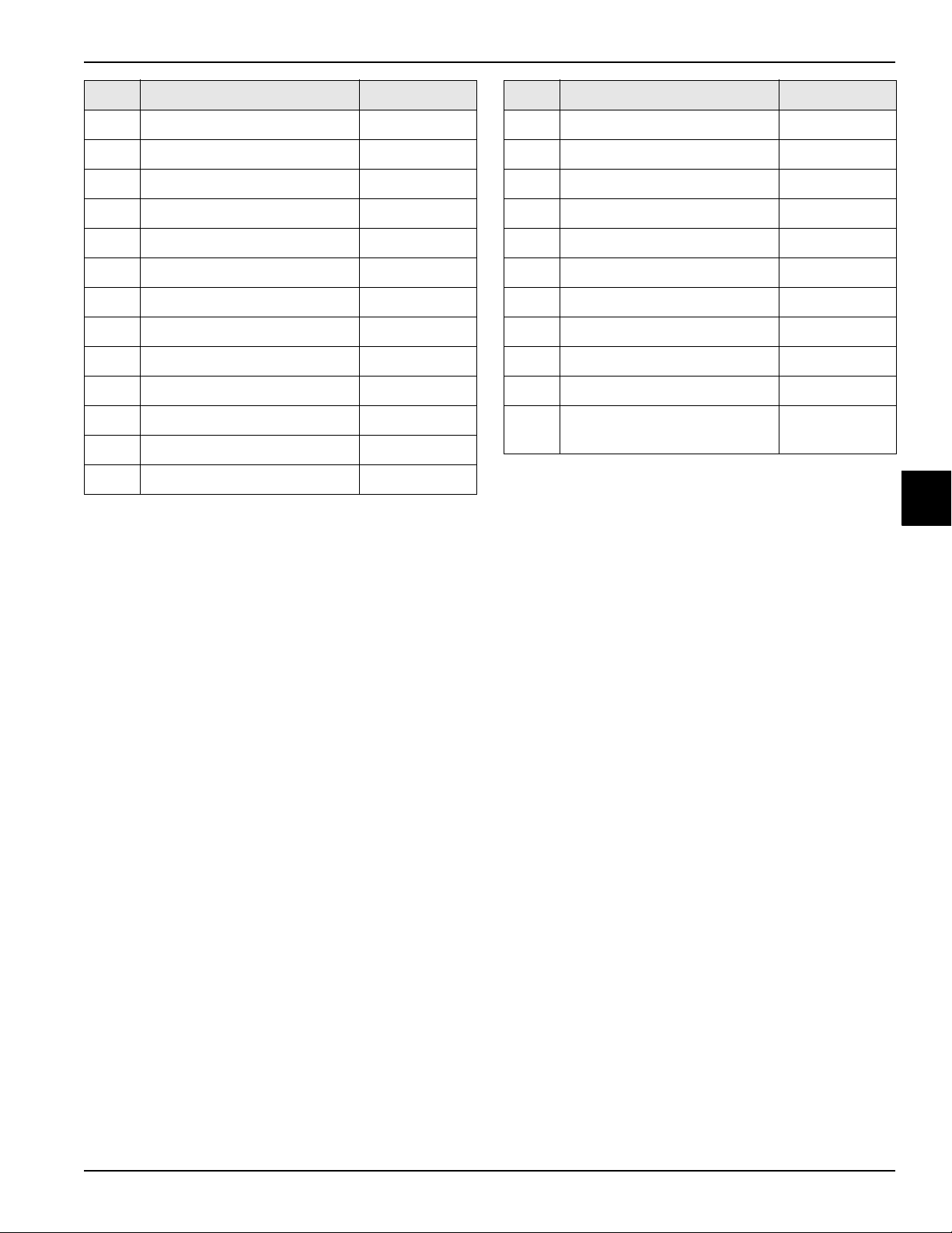
PARTS
Item Description Part No.
58a Cap-Agitator Housing 080827
58b O-ring-1-3/8 OD X .070W 017395
58c Magnet A.-Agitator-Inner 066937
58d Screw-4-40X1/4 Socket 600165
58e Plate-Holding-Agitator 056587
58f Bushing-Agitator Magnet 057342
58g Screw-8-32X3/16 Socket 006812
58h Motor-Agitator-24VAC 050535-03
58i Body-Agitator Housing 056588
59 Probe A.-Mix X56912
60 Spacer-Probe-Mix-Upper 056910
61 O-ring-1-3/8 OD X .070W 017395
62 Spacer-Probe-Mix-Middle 056907
Item Description Part No.
63 Spacer-Mix Probe 056985
64 Clip-Retainer-Mix Pump 044641
65 Pump A.-Mix Simplified S.S. See page 4-37
66 Tube A.-Feed-Hopper S.S. X56521
67 Pin-Retaining-Hopper CVR 043934
68 Kit-Valve Repair 069559-1
69 Screw-10-32X2-1/4 Slot. RD 057610
70 Probe-Mix-Out 056908
71 Nut-10-32 Hex Mach Screw 005598
72 Nut-1/4-20 Finished Hex 000707
73 Valve-TREV 1/4ODFX3/8 W/
Strainer
063951-1
*Not Shown
4
Parts
Models C708/C709/C716/C717
4-5
Page 94

PARTS
4
2
3
1
20
19
15
14
16
12
10
9
17
18
9
2
13
11
9
5
6
7
8
Operator Parts (Model C708)
4
Figure 4-2
4-6
Models C708/C709/C716/C717
Parts
Page 95

C708 Operator Parts Identification
PARTS
Item Description Part No.
1 Panel-Side-Left 056963
2 Pan-Drip 11-5/8 Long 027503
3 Pin-Retaining-Hopper CVR 043934
4 Kit A.-Cover-Hopper X65368
5 Blade A.-Agitator X56591
6 Pump A.-Mix Simplified S.S. See page 4-37
7 Panel-Rear 056077
8 Pan A.-Drip 5 1/2" Long X56074
9 Screw-1/4-20X3/8 011694
10 Panel A-Side-Right X57871
Item Description Part No.
11 Panel A.-Front-Upper X59423
12 Cover-Access-Front-R. 056933
13 Stud-Nose Cone 055987
14 Screw-10X3/8 Slotted Hex 015582
15 Cover-Access-Left 056946
16 Filter-Air-19.25LX15.50HX.70 052779-16
17 Panel A.-Front-Lower X81480
18 Shelf-Tray-Drip 056076
19 Tray-Drip *Black 056858
20 Shield-Splash *SS 049203
4
Parts
Models C708/C709/C716/C717
4-7
Page 96

PARTS
58
62
59
63
60
61
64
65
56g
56f
56d
56a
57
55
56b
56c
56e
56h
56i
54
5
6
4
3
2
1d
1c
1b
1
1a
46
7
8
9
10
11
12
13
14
15
16
17
9
53
50
51
52
30
47
48
49
45
44
43
30
39
30
40
41
30
125 42
36
37
38
37
17
33
34
35
32a
32
32a
31
28
29
27
26a
26
66a
25
66
24
23
22
21
18
20
19
67
Model C709 Exploded View
4
4-8
Figure 4-3
Models C708/C709/C716/C717
Parts
Page 97

Model C709 Exploded View Parts Identification
PARTS
Item Description Part No.
1 Shell A.-Insulated X58858-SER
1a Bearing-Rear Shell 031324
1b Washer-Bearing Lock 012864
1c Nut-Bearing 028991
1d Guide-Drip Seal 028992
2 Coupling-Drive 3/4 Hex 012721
3 Gear A.*Reducer 4.21:1 021286-SER
4 Screw-5/16-18X2-3/4 Hex 004191
5 Pulley-2AK74-5/8 027822
6 Belt-AX39 023874
7 Motor-1.5 HP Caps 056865-27
8 Pulley-2AK22 X .625-.6265 016403
9 Nut-1/4-20 Flange Lock 017523
10 Clamp-Mounting 012257
11 Screw-1/4-20X5/8 Serrated 017522
12 Bushing-Rubber Mount 012258
13 Screw-5/16-18X7/8 SERR 017973
14 Hinge A.-Motor X25796
15 Spring-Comp.970X.115X2.00 025707
16 Washer-5/16 USS Flat CR3 000651
17 Nut-5/16-18 Flange Nut 017327
18 Filter-Air-19.25LX15.50HX.70 052779-16
19 Guide-Filter-Left 056941
20 Guide-Filter-Right 081476
21 Condenser-AC 16X16 3 Row 056944
22 Shroud A.-Condenser X56922
23 Ring A.-Air Flow-Cond. X57006
24 Motor-Fan 185W 500302-27
25 Screw-10-32X1/2 Serrated 020982
26 Kit A.-Valve-OPR X57008-3
26a Strainer-Cone Mesh 5/8 OD 062299
27 Kit-Valve Repair 069559-1
28 Accumulator-Copper 047062
Item Description Part No.
29 Switch-Press 220 CO/270 CI 064282
30 Screw-10X3/8 Slotted Hex 015582
31 Dryer-Filter-HP62-3/8 048901
32
Tube-Capillary (See page 4-44)
or
*32
Thermostatic Expansion Valve
32a Strainer-Cone Mesh 1/4 062298
33 Cap-Rubber Mount 011844
34 Kit-Mounting-Compressor X88073
35 Screw-5/16-18X1-3/4 019691
36 Compressor AWA2480ZXN 081487-27
37 Valve-Access-1/4MFL X 3/8 053565
38 Switch-Pressure 440 PSI 048230
39 Panel A.-Front-Lower X81480
40 Screw-1/4-20X3/8 SLTD 011694
41 Cover-Access-Front-R. 056933
42 Nut-10-32 Flange Locknut 020983
43 Cover-Access-Left 056946
44 Box A.-Cap and Relay See page 4-32
45 Guide-Drip Pan-*SERV* 087637
46 Stud-Nose Cone 055987
47 Panel A.-Front-Upper X59423
48 Switch-Toggle-DPDT 054809
49 Plate A.-DEC X58860-SER
50 Screw-8X1/4 SLTD Hex 009894
51 Switch A.-Draw See page 4-34
52 Control A. See page 4-25
53 Cover-Control Box 056929
54 Pin-Retaining-Hopper CVR 043934
55 Blade A.-Agitator X56591
56a Cap-Agitator Housing 080827
56b O-ring-1-3/8 OD X .070W 017395
56c Magnet A.-Agitator-Inner 066937
084538
057002
4
Parts
Models C708/C709/C716/C717
4-9
Page 98

PARTS
Item Description Part No.
56d Screw-4-40X1/4 Socket 600165
56e Plate-Holding-Agitator 056587
56f Bushing-Agitator Magnet 057342
56g Screw-8-32X3/16 Socket 006812
56h Motor-Agitator-24VAC 050535-03
56i Body-Agitator Housing 056588
57 Probe A.-MIX X56912
58 Spacer-Probe-Mix-Upper 056910
59 Probe-Mix-Out 056908
4
Item Description Part No.
60 Spacer-Probe-Mix-Middle 056907
61 Spacer-Mix Probe 056985
62 Screw-10-32X2-1/4 Slot RD 057610
63 O-ring-1-3/8 OD X .070 W 017395
64 Nut-10-32 Hex Mach Screw 005598
65 Nut-1/4-20 Finished Hex 000707
66 Kit A.-Valve-EPR X57009-3
66a Strainer-Cone Mesh 5/8 062299
67 Valve-Trev 1/4ODFX3/8 W/
Strainer
063951-1
4-10
Models C708/C709/C716/C717
Parts
Page 99

Operator Parts (Model C709)
5
6
7
9
8
4
3
2
1
19
18
17
15
16
11
13
12
11
14
10
PARTS
4
Parts
Figure 4-4
Models C708/C709/C716/C717
4-11
Page 100

PARTS
C709 Operator Parts Identification
Item Description Part No.
1 Panel-Side-Left 056963-SP1
2 Pin-Retaining-Hopper CVR 043934
3 Blade A.-Agitator X56591
4 Kit A.-Cover-Hopper X65368
5 Orifice 022465-100
6 O-ring-3/8 OD X .070W 016137
7 Tube A.-Feed-SC-Inner-5/32 X32824-2
8 Tube A.-Feed-Outer-HT X34641
9 O-ring-.643 OD X .077W 018572
10 Panel-Rear 056077-SP1
4
Item Description Part No.
11 Screw-1/4-20X3/8 011694
12 Pan-Drip 11-5/8 Long 027503
13 Panel A-Side-Right X57871
14 Panel A.-Front-Upper X59423
15 Panel A.-Front-Lower X81480
16 Stud-Nose Cone 055987
17 Shelf-Tray-Drip 056076
18 Tray-Drip 056858
19 Shield-Splash 049203
4-12
Models C708/C709/C716/C717
Parts
 Loading...