

Tascam DM-3200 Owners manual
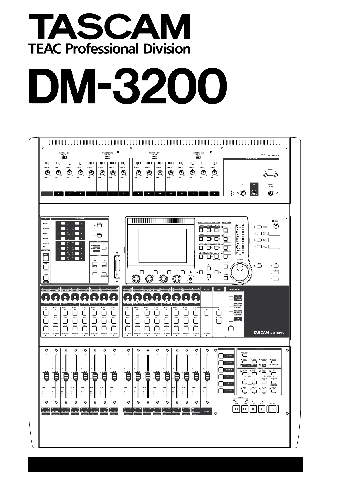
Digital Mixing Console
D001865710A
OWNER’S MANUAL
IMPORTANT SAFETY PRECAUTIONS
For U.S.A
TO THE USER
This equipment has been tested and found to
comply with the limits for a Class A digital device,
pursuant to Part 15 of the FCC Rules. These
limits are designed to provide reasonable
protection against harmful interference when the
equipment is operated in a commercial
environment. This equipment generates, uses,
and can radiate radio frequency energy and, if
not installed and used in accordance with the
instruction manual, may cause harmful
interference to radio communications.
Operation of this equipment in a residental area
is likely to cause harmful interference in which
case the user will be required to correct the
interference at his own expense.
CAUTION
Changes or modifications to this equipment not
expressly approved by TEAC CORPORATION
for compliance could void the user’s authority to
operate this equipment.
For the consumers in Europe
WARNING
This is a Class A product. In a domestic environment, this
product may cause radio interference in which case the
user may be required to take adequate measures.
Pour les utilisateurs en Europe
AVERTISSEMENT
Il s’agit d’un produit de Classe A. Dans un environnement
domestique, cet appareil peut provoquer des
interférences radio, dans ce cas l’utilisateur peut être
amené à prendre des mesures appropriées.
Für Kunden in Europa
Warnung
Dies is eine Einrichtung, welche die Funk-Entstörung
nach Klasse A besitzt. Diese Einrichtung kann im
Wohnbereich Funkstörungen versursachen ; in diesem
Fall kann vom Betrieber verlang werden, angemessene
Maßnahmen durchzuführen und dafür aufzukommen.
CE Marking Information
a) Applicable electromagnetic environment: E4
b) Peak inrush current: 8 A
Ü
The lightning flash with arrowhead symbol, within an equilateral triangle, is intended to alert the
ÿ
Ÿ
This appliance has a serial number
located on the rear panel. Please record
the model number and serial number and
retain them for your records.
Model number
Serial number
2 TASCAM DM-3200 Owner’s Manual
user to the presence of uninsulated “dangerous voltage” within the product’s enclosure that
may be of sufficient magnitude to constitute a risk of electric shock to persons.
The exclamation point within an equilateral triangle is intended to alert the user to the presence
of important operating and maintenance (servicing) instructions in the literature accompanying
the appliance.
CAUTION: TO REDUCE THE RISK OF ELECTRIC SHOCK, DO NOT REMOVE
COVER (OR BACK). NO USER-SERVICEABLE PARTS INSIDE. REFER SERVICING TO QUALIFIED SERVICE PERSONNEL.
WARNING: TO PREVENT FIRE OR SHOCK
HAZARD, DO NOT EXPOSE THIS
APPLIANCE TO RAIN OR MOISTURE.

IMPORTANT SAFETY INSTRUCTIONS
1 Read these instructions.
2 Keep these instructions.
3 Heed all warnings.
4 Follow all instructions.
5 Do not use this apparatus near water.
6 Clean only with dry cloth.
7 Do not block any ventilation openings. Install in
accordance with the manufacturer’s instructions.
8 Do not install near any heat sources such as radi-
ators, heat registers, stoves, or other apparatus
(including amplifiers) that produce heat.
9 Do not defeat the safety purpose of the polarized
or grounding-type plug. A polarized plug has
two blades with one wider than the other.
Grounding type plug has two blades and a third
grounding prong. The wide blade or the third
prong are provided for your safety. If the provided plug does not fit into your outlet, consult
an electrician for replacement of the obsolete
outlet.
10 Protect the power cord from being walked on or
pinched, particularly at plugs, convenience
receptacles, and the point where they exit from
the apparatus.
11 Only use attachments/accessories specified by
the manufacturer.
12 Use only with the cart, stand, tripod, bracket, or
table specified by the manufacturer or sold with
the apparatus. When a cart is used, use caution
when moving the cart/apparatus combination to
avoid injury from tip-over.
13 Unplug this apparatus during lightning storms or
when unused for long periods of time.
14 Refer all servicing to qualified service person-
nel. Servicing is required when the apparatus has
been damaged in any way, such as power-supply
cord or plug is damaged, liquid has been spilled
or objects have fallen into the apparatus, the
apparatus has been exposed to rain or moisture,
does not operate normally, or has been dropped.
● Do not expose this apparatus to drips or
splashes.
● Do not place any objects filled with liquids, such
as vases, on the apparatus.
● Do not install this apparatus in a confined space
such as a book case or similar unit.
● The apparatus draws nominal non-operating
power from the AC outlet with its POWER
switch in the off position.
● The apparatus should be located close enough to
the AC outlet so that you can easily grasp the
power cord plug at any time.
● An apparatus with Class I construction shall be
connected to an AC outlet with a protective
grounding connection.
TASCAM DM-3200 Owner’s Manual 3

Contents
1 – Introduction
Computer (DAW) integration ...................................... 9
Other key points .......................................................... 9
Please read this manual ............................................... 9
About the DM-3200 ....................................... 10
Inputs ....................................................................... 10
Channel modules .................................................... 10
Channel destinations .............................................. 11
Outputs .................................................................... 11
Effects ......................................................................... 11
Unpacking the DM-3200 ............................... 11
About the manual ......................................... 12
What’s in the manual ................................................. 12
1, “Introduction” (page 9) ...................................... 12
2, “Basic operational concepts” (page 16) ............. 12
3, “Connections” (page 38) ..................................... 12
4, “Routing & assignment” (page 46) .................... 12
5, “Channel modules” (page 59) ............................ 12
6, “Effects” (page 81) .............................................. 12
7, “MIDI” (page 91) ................................................. 12
8, “Remote operation” (page 93) ........................... 12
9, “Specifications” (page 102) ................................ 12
Notes and warnings ................................................... 12
Special notes for touch-sensitive faders ...... 13
Copyright, etc. ............................................... 13
The features of the DM-3200 ........................ 14
Control section ........................................................... 15
Monitoring section ..................................................... 15
Module & layer control section ................................. 15
Encoder section .......................................................... 15
Modifier section ......................................................... 15
Library section and CF card slot ................................ 15
Machine control section ............................................ 15
Analog input section .................................................. 15
2 – Basic operational concepts
Smart keys .................................................................. 16
What’s on the screen? ............................................... 16
Jumping to commonly-used screens ......................... 17
Setting a USER screen ............................................. 17
Fader layers ................................................................ 18
Special controls .............................................. 18
The PODs ..................................................................... 18
Encoders ......................................................... 20
Encoder mappings ...................................................... 20
Pan mode ................................................................. 20
Aux mode ................................................................ 20
GATE/DYN dynamics processor mode ................... 20
EQ ............................................................................. 21
SND AUX 1–2 ........................................................... 21
PAN AUX 1–2 ........................................................... 21
LVL BUSS .................................................................. 21
LVL AUX ................................................................... 21
LVL CH 1–16, 17–32, 33–48 ..................................... 21
Reading the encoder indicators ................................ 21
Pan settings ............................................................. 21
EQ settings .............................................................. 22
Module levels and AUX sends ............................... 23
Dynamics settings ................................................... 23
The FLIP key ............................................................. 23
Encoder behavior ....................................................... 23
CF cards ...........................................................24
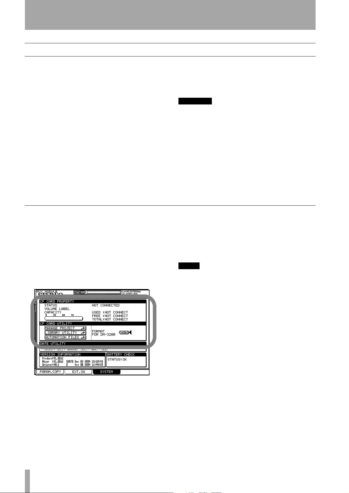
Formatting a new card ...............................................24
Shutting down the DM-3200 .........................25
IMPORTANT CAUTION!!! ........................................25
How to shut down the DM-3200 ...........................25
Starting up the DM-3200 ...........................................25
About projects and libraries ..........................26
Setting the date and time ..........................................27
Creating a new project ...............................................27
Using a template .....................................................27
Managing projects ......................................................28
Loading a project .....................................................28
Copying a project ....................................................28
Deleting a project ....................................................28
Renaming a project ........................................28
Saving project data ....................................................29
Library management ......................................30
Using library banks .................................................30
Viewing library entries ...........................................31
Recalling library entries ..........................................31
Storing library entries .............................................31
Deleting library entries ...........................................31
Library utilities ............................................................31
Target parameters ...................................................31
Source parameters ..................................................32
Naming library entries ...................................32
Options ...........................................................32
SETUP screen ...............................................................32
UPPER BAR DISPLAY ................................................33
LOCATE DISPLAY mode ...........................................33
ENCODER OPERATION mode ..................................33
LIBRARY DIRECT KEY OPERATION ..........................33
OL/STATUS LED TYPE ..............................................33
FADER SENSITIVITY .................................................33
PREFERENCES ..............................................................34
Fader Auto MODULE Select ....................................34
CH SOLO Key Auto MODULE Select .......................34
Select MODULE Return ...........................................34
ST Link by SEL key ...................................................34
SEL Key Follows Fader Layer Status .......................34
Meter Follows SEL key ............................................34
Automation fader OFF ............................................34
Balance Level CENTER:0dB ......................................34
AUX Mute follows CH Mute ...................................34
Encoder Mode Follows Current Screen ..................34
Current Screen Follows Encoder Mode ..................34
BUSS PAN Follows ST PAN ......................................34
BUSS Link/BUSS PAN are Linked ............................35
SOLO ..........................................................................35
MODE SELECT ..........................................................35
SOLO LINK ................................................................35
SOLO TYPE ...............................................................35
INPLACE SOLO DEFEAT ...........................................35
Utilities ............................................................36
UTILITY copying ..........................................................36
SWITCH utility .............................................................37
Talkback ...................................................................37
Machine Control ......................................................37
Other functions .......................................................37
Polarity .....................................................................37
4 TASCAM DM-3200 Owner’s Manual

Contents
3 – Connections
Analog connections ........................................39
Mic/line connections .................................................. 39
Channel inserts ........................................................ 39
2 TR IN ......................................................................39
ASSIGNABLE RETURNS ............................................39
Analog outputs ...........................................................40
STEREO OUT ............................................................40
ASSIGNABLE SENDS ................................................ 40
Monitoring (CR OUTPUTS) ......................................40
Monitoring (STUDIO OUTPUTS) .............................40
Digital connections .........................................40
Digital audio I/O ......................................................... 40
TDIF I/O .................................................................... 40
ADAT “lightpipe” OUT & IN .................................... 40
CASCADE ..................................................................40
Digital inputs and outputs .....................................40
Digital I/O setup .........................................................41
Digital inputs ........................................................... 41
Mute Defeat ............................................................ 41
Stereo output ..........................................................41
Slot card configuration ..............................................42
IF-AN/DM .................................................................42
IF-AE/DM ..................................................................42
IF-TD/DM ..................................................................42
IF AD/DM ................................................................. 42
Other connections ..........................................42
MIDI connections (IN, OUT and THRU) .................. 42
RS-422 serial control terminal ................................42
TIME CODE ...............................................................42
WORD SYNC (IN and OUT/THRU) ...........................42
TO METER ................................................................ 43
FOOT SW .................................................................. 43
USB ........................................................................... 43
Power input ............................................................. 43
Clock setting ...................................................44
Fs MODE ...................................................................44
Checking the clock ..................................................44
Varispeed clocking .................................................. 44
Clock change action ................................................44
Changing the clock .................................................. 45
Clock phase .............................................................. 45
OUT SPEED ............................................................... 45
4 – Routing & assignment
Routing ............................................................47
Input routing .............................................................. 47
Batch routing ...........................................................48
Flipping the channels ..............................................48
Loopback options .................................................... 48
Digital input selection ............................................. 48
Output routing ........................................................... 49
Slot card outputs ..................................................... 49
Insert patching ............................................................50
Send/return linking ................................................. 50
Channel-to-buss assignment .........................51
Assignment using the front panel ............................ 51
Using the assignment screens ................................ 51
Pan switch ................................................................52
Surround assignments ............................................ 53
Non-channel assignments ...................................... 53
Bulk assignment ......................................................53
Buss panning ...........................................................53
Monitoring ..................................................... 54
Selecting the CR source ..............................................54
Studio cue source .......................................................55
Talkback, etc. ..............................................................56
Talkback source .......................................................56
Slate definition ........................................................56
Oscillator and noise generator ..................................56
Oscillator destination ..............................................56
Meters .........................................................................57
Meter ballistics .........................................................57
On-screen meter selection ......................................57
Metering points .......................................................57
Soloing ........................................................................58
5 – Channel modules
General principles .......................................................59
ASSIGN PARAMETERS screen ..................................59
Global module settings .................................60
Input and return display .........................................60
EQ display and button ............................................60
GATE display and button ........................................60
COMP/EXP display and COMP button ....................60
Compressor/expander point button ......................60
Meters and pick-off point button ..........................60
Fader .........................................................................60
MUTE button ............................................................60
PAN (BALANCE) control ...........................................60
PAN follow button ..................................................60
INSERT button ..........................................................60
Phase button ............................................................60
AUX1-2 button .........................................................61
STEREO button .........................................................61
Group assignment displays .....................................61
Fader control ...............................................................61
Master screen ...........................................................61
Dynamics processors ...................................... 62
LINK ..........................................................................62
Trigger mode (
Trigger selection ......................................................62
Turning the processors on and off .........................62
Gates (input channels 1–32) .......................................63
GATE .........................................................................63
Threshold (
Range (
Gate attack time ......................................................63
Hysteresis (
Gate hold time (
Gate decay time (DECAY) ........................................63
Compressor/expanders ..............................................63
COMP/EXPAND ........................................................63
Insert point (
Threshold .................................................................63
Compression/expansion ratio .................................63
Attack time ...............................................................63
Release time .............................................................63
Auto make-up ..........................................................64
Output gain ..............................................................64
Library jump buttons ...............................................64
Preset dynamics library entries .................................64
Compressor/expander library entries ....................64
Gate library entries ..................................................65
Trigger settings ...........................................................65
TRG MOD
THRESH
RANGE
) ........................................................63
HYST
) .....................................................63
HOLD
INS PNT
) .......................................62
) .................................................63
) ............................................63
) .............................................63
TASCAM DM-3200 Owner’s Manual 5

Contents
EQ .................................................................... 66
Encoders and EQ ..................................................... 66
EQ library .................................................................... 67
Aux and buss setup ....................................... 68
Aux send screens (unlinked) .................................. 68
Copying settings between aux sends and channel
levels ..................................................................... 68
Batch setting ........................................................... 68
Source selection ...................................................... 69
Aux send pan/balance screens (linked) ................. 69
Using the encoders ................................................. 69
Module setup ................................................. 70
INPUT/RETURN selection ........................................ 70
GATE switching ....................................................... 70
AUX 1-2 SOURCE ..................................................... 70
Dynamics insert point ............................................. 70
Dynamics on/off ...................................................... 70
Assignable insert position ...................................... 70
Phase control ........................................................... 70
Module delay .......................................................... 70
Digital trim .............................................................. 71
Dithering (stereo buss module only) ..................... 71
Pan and balance settings ........................................ 71
Phase/trim/delay ........................................................ 71
Phase ........................................................................ 71
Digital trim .............................................................. 71
Delay ........................................................................ 72
Stereo linking ............................................................. 72
Balance ..................................................................... 73
Linked dynamics ...................................................... 73
Mute groups ............................................................... 73
Clearing groups ....................................................... 74
Grouping groups ..................................................... 74
Linking fader groups to mute groups ................... 74
Fader groups ............................................................... 74
Surround operations ..................................... 75
Changing surround mode .......................................... 75
Buss assignments .................................................... 75
Assigning channels to surround busses ................... 75
Surround panning ...................................................... 76
Module screen ......................................................... 76
Pattern panning ...................................................... 77
Using the cursor keys ............................................. 77
Jump keys ................................................................ 77
Pan mode off ........................................................... 78
LFE level ...................................................................... 78
Snapshots ....................................................... 79
Snapshot library management .................................. 79
Storing snapshots ...................................................... 80
Information about a snapshot .................................. 80
6 – Effects
Routing the effects ........................................ 81
Setting up the effects .................................... 81
TASCAM effect parameters ....................................... 82
TC Works effect parameters ...................................... 83
Effect libraries ................................................ 84
Preset TC Reverb effects ............................................ 84
Preset TASCAM effects ...............................................87
7 – MIDI
MIDI port switching and filtering .................91
Program Change messages and the
DM-3200 .......................................................92
Setting the MIDI channels ......................................92
Batch setup ..............................................................92
MIDI Implementation Charts .........................92
8 – Remote operation
Selecting devices for transport control ........93
Deleting devices from the list ....................................94
Auto-detection of devices ..........................................94
Selecting the control type for the devices ................94
STATE .......................................................................94
DEVICE ......................................................................94
ID ..............................................................................94
CHASE .......................................................................95
TRA ...........................................................................95
REC ............................................................................95
All safe .....................................................................95
Transport mapping memories ...................................95
To use a transport mapping ......................................96
Viewing the transport mappings ..............................96
Editing a mapping ......................................................96
Machine control setup ................................... 97
Edit Frames ..................................................................97
Cueing mode ...............................................................97
Play Mode ...................................................................97
AUTO ........................................................................97
DEFERRED .................................................................97
IMMEDIATE ..............................................................97
Play Command Type ...................................................97
Record Command Type ..............................................98
Locate Preroll ..............................................................98
Location memories .........................................99
Selecting the location point display ..........................99
Storing a location memory “on the fly” ...................99
Manually entering and editing a location memory .99
Location to a location memory ..................................99
Viewing a list of location memories .......................100
Manual location ........................................................100
Repeat play ...............................................................100
Auto punch operations ............................................101
ALL INPUT and AUTO MON ......................................101
9 – Specifications
Analog audio I/O ..........................................102
Digital audio I/O ...........................................103
Miscellaneous I/O connections ....................103
Equalization ..................................................104
System performance ....................................104
Physical characteristics .................................104
Dimensional drawing ...................................105
Messages and troubleshooting ...................105
Block diagram ...............................................116
Level diagram ...............................................117
6 TASCAM DM-3200 Owner’s Manual

List of Figures
1 ––Introduction
Figure 1.1: Basic logical components of the
DM-3200 . . . . . . . . . . . . . . . . . . . . . . . . . . . . . . . 10
Figure 1.1: Overview of the DM-3200 . . . . . . . . . . . . 14
2 ––Basic operational concepts
Figure 2.1: Control keys . . . . . . . . . . . . . . . . . . . . . . 16
Figure 2.2: Explanation of the top line of screen
displays . . . . . . . . . . . . . . . . . . . . . . . . . . . . . . . . 17
Figure 2.3: POD controls . . . . . . . . . . . . . . . . . . . . . . 18
Figure 2.4: POD knobs used in a multi-control screen 19
Figure 2.5: POD knob 4 used as list selector . . . . . . . 19
Figure 2.6: POD keys 2 through 4 used as soft keys . 19
Figure 2.7: POD 1 used with a pull-up menu list . . . . 19
Figure 2.8: POD keys used to select sub-screens . . . 19
Figure 2.9: POD keys 2 and 4 used to jump to other
screens (library screens) . . . . . . . . . . . . . . . . . . . 19
Figure 2.10: Encoder functions . . . . . . . . . . . . . . . . . 20
Figure 2.11: Encoders in pan mode . . . . . . . . . . . . . . 21
Figure 2.12: Encoders in EQ gain mode . . . . . . . . . . 22
Figure 2.13: Encoders in EQ frequency selection
mode . . . . . . . . . . . . . . . . . . . . . . . . . . . . . . . . . . 22
Figure 2.14: Encoders in frequency Q adjustment
mode . . . . . . . . . . . . . . . . . . . . . . . . . . . . . . . . . . 22
Figure 2.15: Encoders used to make frequency band fil-
ter type selections . . . . . . . . . . . . . . . . . . . . . . . . 23
Figure 2.16: Encoders used to make module level and
aux send adjustments . . . . . . . . . . . . . . . . . . . . . 23
Figure 2.17: ENCODER OPERATION menu item . . . . . 23
Figure 2.18: Formatting a CF card . . . . . . . . . . . . . . . 24
Figure 2.19: Shutting down the DM-3200 . . . . . . . . . 25
Figure 2.20: Powering up the DM-3200 with no previous
shutdown . . . . . . . . . . . . . . . . . . . . . . . . . . . . . . . 25
Figure 2.21: Project structure . . . . . . . . . . . . . . . . . . 26
Figure 2.22: Setting the date and time . . . . . . . . . . . 27
Figure 2.23: The NEW PROJECT page . . . . . . . . . . . . 27
Figure 2.24: The project management page . . . . . . . 28
Figure 2.25: Storing a project . . . . . . . . . . . . . . . . . . 29
Figure 2.26: Library management (gate library shown as
example) . . . . . . . . . . . . . . . . . . . . . . . . . . . . . . . 30
Figure 2.27: Library selection pull-up menu . . . . . . . 30
Figure 2.28: Library utility screen . . . . . . . . . . . . . . . 31
Figure 2.29: Setting and editing titles and memos . . 32
Figure 2.30: The SETUP option screen . . . . . . . . . . . . 33
Figure 2.31: Display top line set to SYSTEM . . . . . . . 33
Figure 2.32: The PREFERENCES screen . . . . . . . . . . . 34
Figure 2.33: SOLO options . . . . . . . . . . . . . . . . . . . . . 35
Figure 2.34: UTILITY copy screen . . . . . . . . . . . . . . . 36
Figure 2.35: UTILITY external switch settings . . . . . . 37
3 ––Connections
Figure 3.1: Overview of rear panel features . . . . . . . 38
Figure 3.2: Analog channel inputs and controls . . . . 39
Figure 3.3: DIGITAL SETUP screen . . . . . . . . . . . . . . . 41
Figure 3.4: IF-AN/DM (at left) and IF-AE/DM (at
right) . . . . . . . . . . . . . . . . . . . . . . . . . . . . . . . . . . 42
Figure 3.5: IF-TD/DM (at left) and IF-AD/DM (at right) 42
Figure 3.6: PROJECT CLOCK screen (high-speed) . . . 44
Figure 3.7: Checking the clock sources . . . . . . . . . . . 44
4 ––Routing & assignment
Figure 4.1: Module facilities on the DM-3200 . . . . . . 46
Figure 4.2: Routing inputs . . . . . . . . . . . . . . . . . . . . . 47
Figure 4.3: Routing outputs . . . . . . . . . . . . . . . . . . . .49
Figure 4.4: Routing inserts . . . . . . . . . . . . . . . . . . . . . 50
Figure 4.5: Assignment keys . . . . . . . . . . . . . . . . . . .51
Figure 4.6: Buss assignment screen (linked busses) .51
Figure 4.7: Buss assignments with the pan switch off 52
Figure 4.8: Surround channel assignment screen . . .53
Figure 4.9: Monitoring and metering controls . . . . . .54
Figure 4.10: Monitor parameters screen . . . . . . . . . . 55
Figure 4.11: Monitor oscillator and communication
screen . . . . . . . . . . . . . . . . . . . . . . . . . . . . . . . . . . 56
Figure 4.12: Metering screen (1st 24 channel module
meters) . . . . . . . . . . . . . . . . . . . . . . . . . . . . . . . . .57
5 ––Channel modules
Figure 5.1: Assign parameters screen . . . . . . . . . . . .59
Figure 5.2: Common “global” module settings . . . . .60
Figure 5.3: Channel fader screen . . . . . . . . . . . . . . . . 61
Figure 5.4: Master fader screen . . . . . . . . . . . . . . . . .61
Figure 5.5: Unlinked DYNAMICS screen (channels 1
through 32) . . . . . . . . . . . . . . . . . . . . . . . . . . . . . .62
Figure 5.6: Linked DYNAMICS screen (channels 1
through 32) . . . . . . . . . . . . . . . . . . . . . . . . . . . . . .62
Table 5.7: Compressor/Expander preset library
entries . . . . . . . . . . . . . . . . . . . . . . . . . . . . . . . . . . 64
Table 5.8: Gate/Expander preset library entries . . . .65
Figure 5.9: Assigning dynamics processor triggers . . 65
Figure 5.10: Module EQ screen . . . . . . . . . . . . . . . . .66
Figure 5.11: EQ library . . . . . . . . . . . . . . . . . . . . . . . . 67
Table 5.12: EQ library presets . . . . . . . . . . . . . . . . . .67
Figure 5.13: Module aux and buss screen . . . . . . . . .68
Figure 5.14: Aux send screen (unlinked) . . . . . . . . . .68
Figure 5.15: Aux pan/balance screen (linked) . . . . . .69
Figure 5.16: Channel module SETUP screen . . . . . . . . 70
Table 5.17: Channel delay . . . . . . . . . . . . . . . . . . . . .70
Figure 5.18: Linked pair balance controls . . . . . . . . . 71
Figure 5.19: Digital trim setting . . . . . . . . . . . . . . . . .71
Figure 5.20: Channel delay screen . . . . . . . . . . . . . . . 72
Figure 5.21: Master delay screen . . . . . . . . . . . . . . . . 72
Figure 5.22: Linking modules . . . . . . . . . . . . . . . . . . .73
Figure 5.23: Stereo linking screen . . . . . . . . . . . . . . .73
Figure 5.24: Mute grouping . . . . . . . . . . . . . . . . . . . .73
Figure 5.25: Clearing a group . . . . . . . . . . . . . . . . . . . 74
Figure 5.26: Grouping groups . . . . . . . . . . . . . . . . . . 74
Figure 5.27: Fader grouping . . . . . . . . . . . . . . . . . . . . 74
Figure 5.28: Selecting surround mode . . . . . . . . . . . .75
Table 5.29: Buss assignments in surround mode . . . .75
Figure 5.30: Surround assignment . . . . . . . . . . . . . . . 76
Figure 5.31: Surround overview . . . . . . . . . . . . . . . . . 76
Figure 5.32: Module surround panning . . . . . . . . . . .76
Figure 5.33: Surround panning (pan mode on) . . . . .77
Figure 5.34: Surround screen (pan mode off) . . . . . .78
Figure 5.35: LFE level . . . . . . . . . . . . . . . . . . . . . . . . . 78
Figure 5.36: Snapshot library . . . . . . . . . . . . . . . . . . . 79
Figure 5.37: Storing a snapshot . . . . . . . . . . . . . . . . .80
TASCAM DM-3200 Owner’s Manual 7

List of Figures
6 ––Effects
Figure 6.1: Internal effect send and return routing . 81
Figure 6.2: Effect library screen . . . . . . . . . . . . . . . . 81
Figure 6.3: Effect setting . . . . . . . . . . . . . . . . . . . . . . 82
Figure 6.4: Common effect parameters (Row 1) . . . . 82
Table 6.5: TASCAM effect parameters . . . . . . . . . . . 82
Table 6.6: TC Reverb effect parameters . . . . . . . . . . 83
Table 6.7: Preset TC Reverb effects . . . . . . . . . . . . . 84
Table 6.8: TASCAM effects . . . . . . . . . . . . . . . . . . . . 87
7 ––MIDI
Figure 7.1: MIDI setup . . . . . . . . . . . . . . . . . . . . . . . . 91
Figure 7.2: MIDI Program Change screen . . . . . . . . . 92
8 ––Remote operation
Figure 8.1: Adding external devices for control by the
DM-3200 . . . . . . . . . . . . . . . . . . . . . . . . . . . . . . . .93
Table 8.2: Control methods . . . . . . . . . . . . . . . . . . . .93
Table 8.3: Supported transport machine control
devices . . . . . . . . . . . . . . . . . . . . . . . . . . . . . . . . .93
Figure 8.4: Machine control setup parameters . . . . . 97
9 ––Specifications
Figure 9.1: Dimensional drawing . . . . . . . . . . . . . . . 105
Table 9.2: Popup messages . . . . . . . . . . . . . . . . . . . 105
Figure 9.3: Block diagram . . . . . . . . . . . . . . . . . . . .116
Figure 9.4: Level diagram . . . . . . . . . . . . . . . . . . . . .117
8 TASCAM DM-3200 Owner’s Manual

1 – Introduction
This section provides an overview of the features and facilities provided by the DM-3200. It also includes an
overview of the operational procedures involved when using the unit. It is important to read this section to gain
a basic understanding of the way that the DM-3200 works before proceeding with setting up and using the
unit.
The DM-3200 provides you with a new and flexible
approach to mixing and recording.
Designed to integrate with the latest Digital Audio
Workstation (DAW) personal computer software as
well as with standalone recorders, it can form the
heart of any recording studio.
Computer (DAW) integration
The DM-3200 can be used with a computer system:
with the built-in USB port, which allows control of
the DAW by the DM-3200, emulating popular controller hardware
Additionally the optional FireWire expansion card
(IF-FW), which provides all the USB functionality,
and also allows multi-channel digital audio to be
transmitted and received between the DM-3200 and
the DAW application.
.
Other key points
Since the DM-3200 is designed with a working environment in mind, full control-room and studio monitoring facilities, as well as talkback, are integrated.
The DM-3200 provides automation facilities which
are independent of any external computer. Mix
moves can easily be recorded, edited and replayed in
the DM-3200 in standalone mode, requiring only a
timecode source (including the internal generator).
Sony P2 9-pin protocols are also provided, allowing
control of other studio equipment from one central
unit.
Working in multiple locations is easier than ever
before, as the DM-3200 works the way you do; in
Full-sized motorized faders, sixteen rotary encoders
with ring LED indicators, a large clear LCD display
and ergonomically-placed dedicated controls help to
make the DM-3200 intuitive, as well as powerful, to
use.
In this second method, the DM-3200 may be used as
an outboard mixer, freeing the computer from this
task, and reserving the DAW for audio editing, etc.
In both cases, the TMCompanion software can be
used for management of the DM-3200. See the documentation accompanying the latest release of the
software for full details of the capabilities of the software with the unit.
NOTE
Some of these features may not be available in the first
release of the DM-3200 firmware.
terms of projects where all information and settings
are stored together for future recall.
The data for projects is stored on industry-standard
CompactFlash cards for easy offline storage, archival
and transportation between facilities.
In addition, computer-aided librarian functions make
it simple to juggle the demands of a busy studio
schedule.
Top-quality internal effects reduce the need for large
outboard racks and allow still further for portability
of projects.
Timecode, word sync, MIDI, 9-pin serial control etc.
are also provided for the widest possible integration
with other equipment in your setup.
Please read this manual
Please take the trouble to read this manual carefully.
Although every attempt has been made to make the
DM-3200 as easy to use as possible, there are many
features that may not be immediately obvious.
A little time spent studying the manual now may save
you a lot of time and effort later on.
TASCAM DM-3200 Owner’s Manual 9
1 – Introduction : About the DM-3200
About the DM-3200
The DM-3200 provides a fully comprehensive range
of I/O facilities. Almost all inputs and internal busses
are “soft”, allowing connections to be patched internally (naturally, routing configurations may be stored
and recalled).
Inputs For analog input, the DM-3200 provides
sixteen balanced inputs, with both high-quality mic
amps, and balanced line connections as well as analog insert points (both mic and line connections may
be made to the same channel at the same time, but
only one may be used at a time). There are also four
assignable send outputs and inputs for external loop
effects.
The digital side comprises three TDIF I/O ports, as
well as ADAT “lightpipe” I/O, and two pairs of stereo S/PDIF or AES/EBU inputs and outputs.
Two TASCAM-standard card slots provide I/O
expansion capabilities, with a variety of digital or
analog options being available, including a FireWire
expansion card for direct high-speed bidirectional
communication between a DAW and the DM-3200.
Channel modules The DM-3200 provides 48
channel modules. These may be freely assigned
internally to the 16 buss modules.
Of these 48 channel modules, 32 are “full-function”
modules with 4-band EQ, digital trim and phase, and
full dynamics processing with compressor/expanders
and gates. The other 16 are more basic in the facilities provided, but still provide full buss assignment
and aux sends.
The first 32 EQ-enabled channels can have two
sources (input and return), which may be freely
assigned, and can be switched, depending on whether
the project is in the recording or tracking stage. See
the section on assignments (“Routing & assignment”
on page 46) for details of how channel sources are
assigned,
³ ³ ³ ³
Mic/Line inputs
Assignable returns
Digital stereo
inputs (x 2)
TDIF inputs
ADAT inputs
Inputs (hardwarte)
Option slots
Cascade
2-track in
(x 16)
(x 4)
(x 24)
(x 8)
32 full-EQ
channels
Mixer channels
16 non-EQ
channels
Assignable internal
inserts (x 16) —
full-EQ channels
only
Direct outs
(x 32)
Aux sends
(x 8)
Busses
(x 16)
Channel destinations
Stereo buss
TDIF x 24
ADAT x 8
Assignable sends
x 4
Option slots
Cascade
Outputs (hardware)
Stereo outs
(analog & digital)
CR outs
Studio outs
Figure 1.1: Basic logical components of the DM-3200
a. Note that cascade connections are not available on the first release of the DM-3200 software.
a
10 TASCAM DM-3200 Owner’s Manual

1 – Introduction : Unpacking the DM-3200
Channel destinations There are 16 busses,
eight aux busses, 16 assignable inserts (not to be confused with the “hard-wired” analog inserts on the
input pre-amps) as well as the stereo buss module.
Outputs from the channels can be assigned to these.
Furthermore, even when working at a sampling frequency of 88.2 kHz or 96 kHz, the DM-3200 retains
the same number of channels and facilities as when
operating at “conventional” sampling frequencies.
Outputs The sources for the outputs (built-in and
optional slot) are then assigned to the actual physical
outputs.
Effects
The DM-3200 incorporates two high-quality digital
effects, including a digital reverb programmed by TC
Work s.
Signals may be routed internally to these effects
using busses or aux sends, and the returns fed back to
mixer channels for inclusion in the mix. Alternatively, the assignable inserts may be used to insert
and effect into the signal path of a channel module.
External effects can be looped through the assignable
analog sends and returns (the returns can then be
assigned to channels), or kept in the digital domain
by using the stereo digital I/O facilities.
Physical outputs available include the built-in TDIF
outputs (3 sets of eight outputs each), and eight channels of ADAT “lightpipe”, as well as two stereo digital and one stereo analog sets of outputs.
Since buss outputs can be assigned to the TDIF and
ADAT ports, this allows all the channels of a surround mix to be recorded together.
The option slot cards typically provide outputs as
well as inputs.
In addition, channels 1 through 32 can use built-in
dynamic processors to provide compression or
expansion either pre- or post-fader.
Gates can be inserted at the inputs, with a wide range
of triggering options.
There are also analog inserts associated with each
mic/line input, which allow additional processors to
be inserted, before the DA converters. These insert
points can also be used to bypass the DM-3200’s
internal mic amps and patch in external mic amps.
Unpacking the DM-3200
The DM-3200’s box contains the items listed below.
When opening the package please be certain all the
items listed are included. If any items are missing,
please consult your TASCAM dealer.
• The DM-3200
•AC power cable
• A 32MB CF card, pre-formatted, and installed in
the card slot of the DM-3200.
• A USB cable
• A CD-ROM containing the utility software and
documentation for the DM-3200 (Windows and
Mac compatible).
•This manual
•The Quick Reference Guide
• Warranty card.
WARNING
The DM-3200 is a large and bulky piece of equipment.
We strongly suggest that you get someone to help you
lift it out of the carton and locate it in the position
where it will be used.
Lifting properly—When lifting, be sure of your footing
and grip. Bend your legs to get close to the DM-3200,
keeping your back straight, and then lift by straightening your legs. Hold the unit close to your body. Avoid
twisting or turning your body while lifting or carrying
the DM-3200.
TASCAM DM-3200 Owner’s Manual 11

1 – Introduction : About the manual
About the manual
Pushed controls on the DM-3200 are referred to as
“keys”.
Their virtual equivalents displayed on screen are
referred to as “buttons”.
Within this manual, the following typographic conventions are used:
What’s in the manual
1, “Introduction” (page 9) This section, pro-
viding an introduction to the DM-3200.
2, “Basic operational concepts” (page 16)
This is important—it gives you basic information on
the way in which you use the DM-3200’s controls
and menu systems, etc. as well as providing an explanation of way in which the DM-3200 stores data.
3, “Connections” (page 38) Provides informa-
tion on how to connect the DM-3200 to other equipment in your setup.
4, “Routing & assignment” (page 46) Since
the DM-3200 is a “soft” console, with many patches
and assignments made through software rather than
physical connections, you should read this section to
understand how the inputs and outputs of the DM3200, as well as the internal connections, are linked
together.
5, “Channel modules” (page 59) This sec-
tion describes the modules which form the basic
“building blocks” of the DM-3200. Most of the mixing work you do on the DM-3200 will use the functions described here.
• The name of a control or connector on the unit is
written in the following way:
• Messages and text shown on the display of the
DM-3200 are shown as follows:
• The name of a control or connector on another unit
is written in the following way: AUX IN.
This section also contains information on using the
DM-3200 in surround modes.
LINE/MIC.
DIGITAL IN 1.
6, “Effects” (page 81) The parameters control-
ling the built-in effects of the DM-3200 are described
here and a list of the preset libraries may also be
found in this section.
7, “MIDI” (page 91) This provides information
on the MIDI capabilities provided by the DM-3200.
8, “Remote operation” (page 93) The DM-
3200 is capable of acting as a remote control unit for
a wide variety of external devices, including DAW
systems. This section explains how to use these capabilities.
9, “Specifications” (page 102) Specifications
of the DM-3200, together with a guide to the popup
messages that appear on screen.
Also note that there are two separate publications in
addition to this manual and the printed Quick Refer-
ence Guide: these cover the automation features of
the DM-3200 and the TMCompanion software,
which are provided as electronic publications in PDF
format.
Notes and warnings
TIP
We give hints and tips on using the DM-3200 in this
way.
NOTE
These notes provide additional explanations for special
cases, etc.
12 TASCAM DM-3200 Owner’s Manual
CAUTION
Cautions show that you may lose data or performance
may suffer if the instructions are not followed.
WARNING
These warnings should be taken very seriously. They
describe situations which can cause injury, or damage to
equipment if the instructions are not followed.

1 – Introduction : Special notes for touch-sensitive faders
Special notes for touch-sensitive faders
The usual rules regarding precision electronic equipment naturally apply to the DM-3200. In addition,
note the following that apply to the touch-sensitive
faders:
Copyright, etc.
Windows, Windows XP, and Windows 2000 are
trademarks of Microsoft Corporation.
Macintosh, MacOS, MacOS X and FireWire™ are
trademarks of Apple Computer.
• The faders need a human finger to operate their
touch-sensitivity. Do not use a pencil, ruler, etc. to
operate them. Even using your fingernails may not
activate the touch-sensitivity.
• The humidity and temperature of your environment
affects the touch-sensitivity of the faders. Under
normal working conditions you should experience
no issues. However, extremes of temperature and/
or humidity may sometimes cause operational
problems.
HUI and Mackie CONTROL are trademarks of
LOUD Technologies Inc.
All other trademarks are the property of their respective holders.
TASCAM DM-3200 Owner’s Manual 13
1 – Introduction : The features of the DM-3200
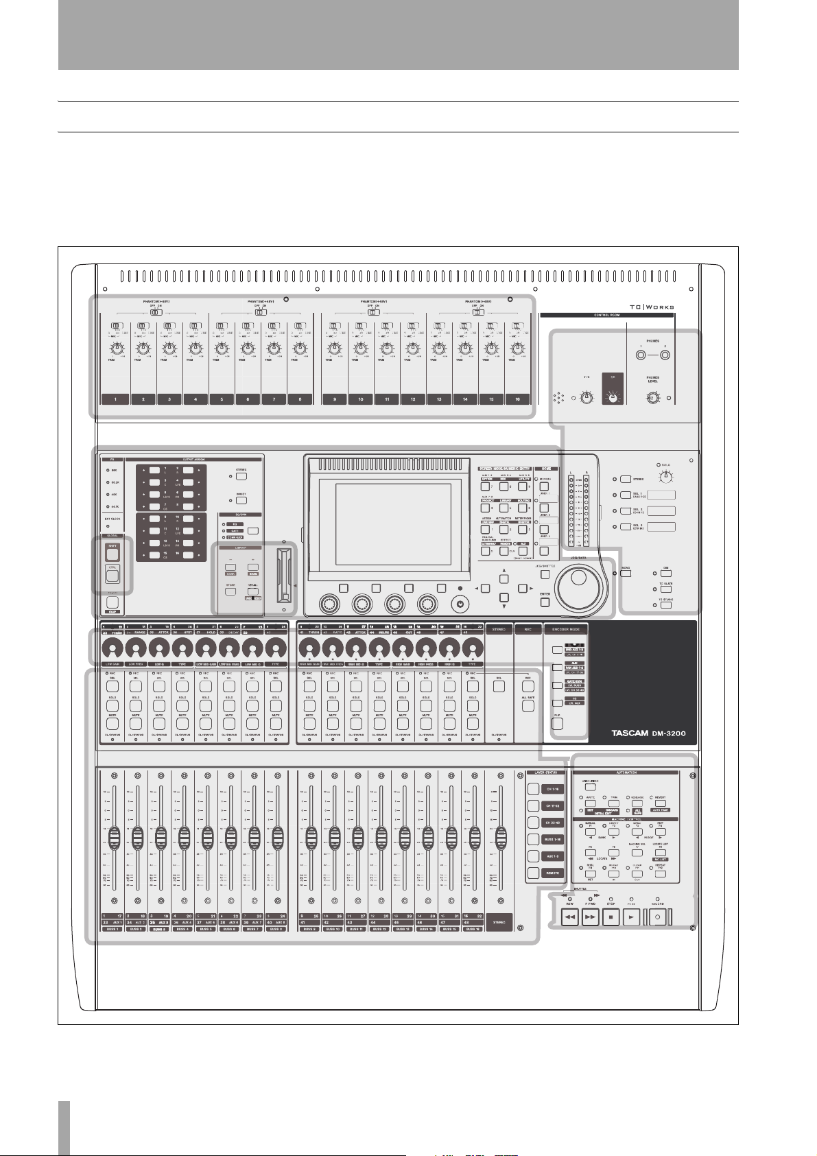
The features of the DM-3200
This section describes the different areas of the DM3200 as well as providing a guide to hooking up
other equipment for use in your studio setup.
Analog input section
Modifier
Control section
keys
The front surface of the DM-3200 may seem a little
intimidating at first, but it is actually remarkably simple, considering the functionality built into the unit.
Controls are logically grouped, depending on their
function:
Monitoring section
Library section
and CF card slot
Module and fader layer section
Encoder section
Machine
control section
Figure 1.1: Overview of the DM-3200
14 TASCAM DM-3200 Owner’s Manual

1 – Introduction : The features of the DM-3200
Control section
This section contains the screen, the dedicated function keys, and the PODs, as well as the cursor keys
and the data dial.
Monitoring section
This section contains the controls for the control
room and studio monitoring and cueing controls, as
well as the talkback microphone and slate controls.
The main stereo meters are also in this section.
Module & layer control section
The faders and module control keys are in this section, together with the keys used to select the different layers.
See “Fader layers” on page 18 for details of how the
fader layers are used on the DM-3200.
The operation of this section is described in more
detail in “Basic operational concepts” on page 16,
which you should read in order to gain an understanding of how the PODs, etc. are used.
See “Monitoring” on page 54 for details of this section’s operation.
The
SEL keys are used to select the modules to be
edited. This can also be done with the touch-sensitive
faders.
Encoder section
The use of the encoders is described in “Encoders”
on page 20.
Modifier section
These are keys which when pressed and held, affect
the behavior of other keys.
Library section and CF card slot
These keys perform recall, etc. of library entries. The
CF card slot is used with a CF card to store projects
and the data associated with these project.
Machine control section
These controls are used to control a device (external
hardware recorder, or DAW) connected to the DM3200 using MIDI, USB or the 9-pin serial control
protocol.
Analog input section
These are the built-in mic/line inputs and inserts. See
the details later in this section (“Mic/line connections” on page 39) for details of how to connect and
use them.
See this section for a complete description of how the
indicators surrounding the encoders are lit when the
encoders perform different functions.
See “Remote operation” on page 93 for details of
how to set up and use these controls in your projects.
TASCAM DM-3200 Owner’s Manual 15
2 – Basic operational concepts
NOTE
Please take the time to read and understand this section, so that you understand how the basic navigation
and parameter editing operations are performed.
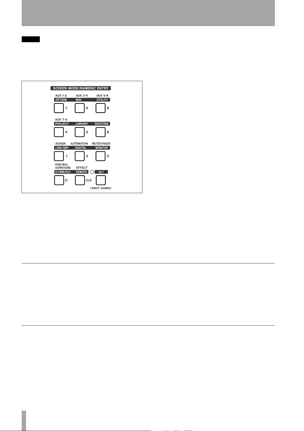
Dedicated screen mode selection keys provide access
to the different screens shown on the LCD display:
Figure 2.1: Control keys
Press one of these keys to access the screen marked
above the key in “normal” (for example, key
used to select the
AUX 7-8 screen).
4 is
For the alternative screen available from many keys,
press the
ALT key so that the ALT indicator lights
(see “Smart keys” on page 16 for details of the
behavior of this key), and then the appropriate key to
select the screen whose title is written in inverted
characters above the key. For example, key
mally brings up the
with the
ALT key brings up the OPTION screens. Note
that some keys (e.g. the
AUX 1-2 screen, but using this key
LIBRARY and ROUTING
7 nor-
keys) are marked as “alternative” screens only, but
these keys do not need the
ALT key to be pressed to
access their screens.
Many screens accessed with these keys include sub-
screens or “pages”. These sub-screens can be
accessed using the POD keys (“The PODs” on
page 18) or repeated presses of the same control key
will cycle through these pages.
Use the cursor keys to navigate around the screen
(sometimes, the dial can also be used to navigate).
Radio buttons (exclusive-or options) or checkboxes
(options) are set and unset using the
ENTER key
when the cursor highlights the option.
When a parameter is selected, the dial is usually used
to change the value.
For non-numerical values changed using the dial,
usually
ENTER should be pressed to confirm the
entry. Note that while the parameter is being edited,
the displayed parameter blinks on screen, and the
cursor cannot be moved until the new value is confirmed with the
ENTER key.
For a few parameters (chiefly connected with the
remote unit location facilities), the number keys can
also be used when the number is selected using
ENTER. Confirm the entry of a value made in this
way by pressing
ENTER.
Smart keys
The DM-3200 features five “smart keys”: the ALT
key and four “talkback” keys (
SLATE
and TO STUDIO). When the status of any of
DIM, MONO, TO
these keys is off, and the key is then pressed very
briefly and released, the status of the key, as shown
by the indicator, is changed to on after the key is
released (latching).
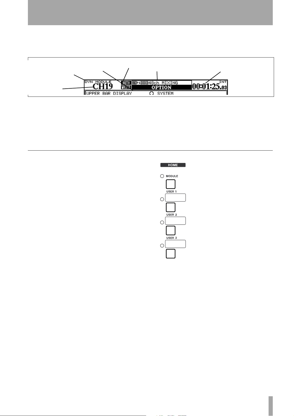
What’s on the screen?
For almost all the screens displayed by the DM-3200,
there are two common areas. The first is at the top,
and we explain that area here (the second is the row
of labels which identify the POD functions
(described in “Special controls” on page 18)).
16 TASCAM DM-3200 Owner’s Manual
If the status of the key is off, and the key is pressed
and held down, the status is only changed as long as
the key is held down (non-latching).
If the status of one of these keys is on, the length of
the key press makes no difference—the key status
changes to off when the key is released.
These top and bottom areas are for display, and their
contents are automatically determined (they cannot
be edited).
2 – Basic operational concepts :
C
lib
On the top row of the top section, the left side shows
(on top) the current encoder mode (see “Encoders”
on page 20) and immediately below that, the cur-
Automation status
Figure 2.2: Explanation of the top line of screen displays
Encoder mode
Currently-selected
module
Screen display
To the right of this, the name and number of the current library entry selected with the direct library
functions are shown, and immediately below that, in
larger letters, the title of the current screen.
Jumping to commonly-used screens
Within a project, it’s likely that you’ll find yourself
using some screens more than others. One of the
main such screens is the module screen, allowing you
to view and change a module’s parameters at a
glance.
rently-selected module or modules. To the right of
this, the current automation settings (on or off, or
global mode) are shown.
urrent
selected by direct recall
rary entry
Current timecode value
Finally, on the right, the current timecode value (with
the source as set up as preference) is displayed.
Note the timecode displayed can be changed as a
setup option. See “UPPER BAR DISPLAY” on
page 33.
For this reason, a dedicated MODULE
key, with indicator, is provided to the
right of the number keys. The module
parameters shown are those of the
module selected using the
SEL keys.
The three
USER keys are used to set
up three commonly-used shortcuts to
screens used frequently within a
project.
Setting a USER screen With the
screen shown to which you want to
make a shortcut, press and hold the
SHIFT and CTRL keys (to the left of
the unit). While holding down these
keys, press one of the
Release all the keys. Next time you
press that
USER key (without the SHIFT and CTRL
keys), the display shows the screen you set
previously.
USER keys.
TASCAM DM-3200 Owner’s Manual 17
2 – Basic operational concepts : Special controls
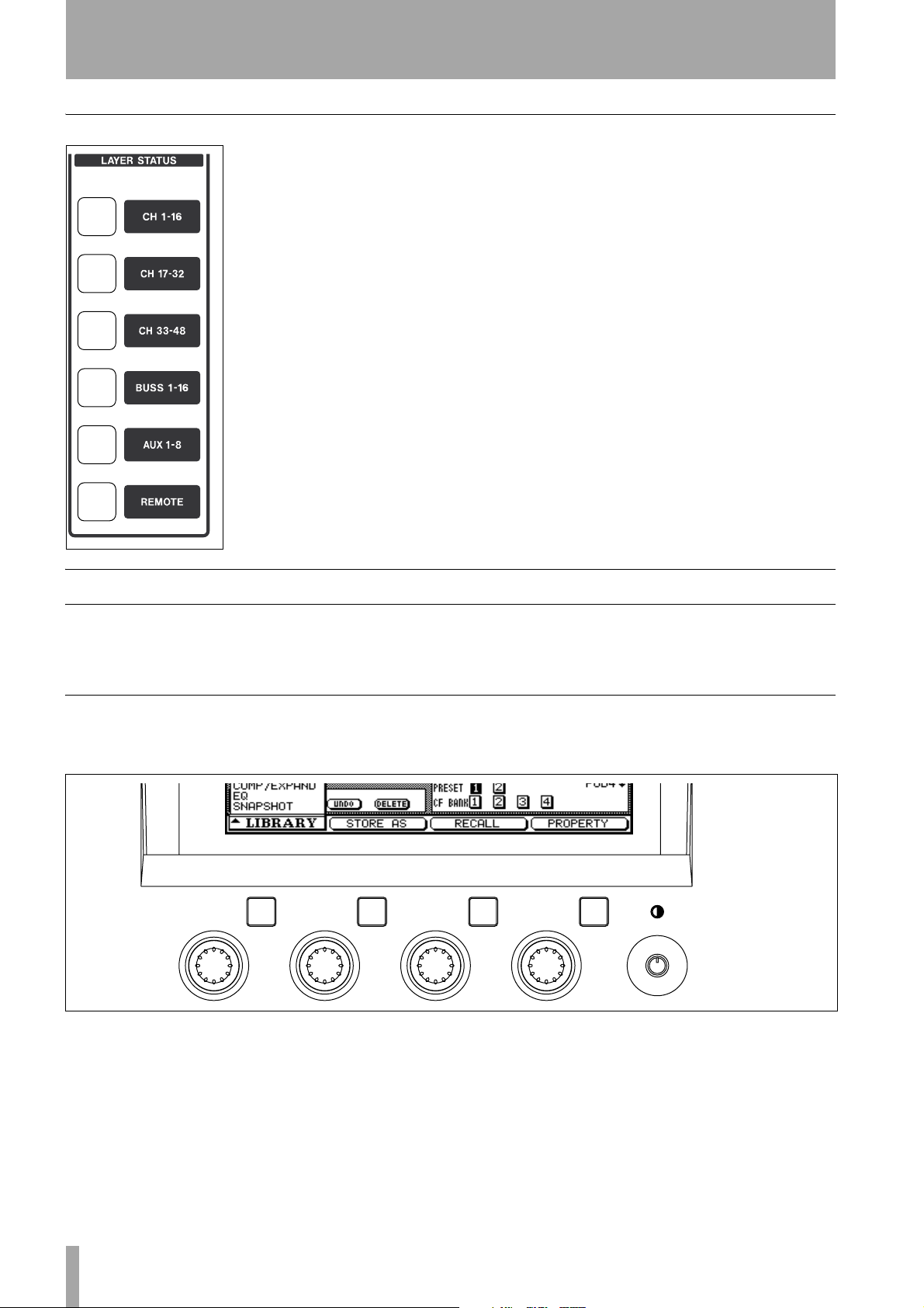
Fader layers
The DM-3200 has sixteen
channel faders and encoders,
but is capable of controlling
48 channels, in addition to
the master aux send and buss
levels.
The faders (and the encoders, when the encoders are
associated with channels)
are therefore arranged in
layers, allowing different
groups of faders to be
accessed.
these keys are pressed, the faders move to the appropriate positions, reflecting the new fader layer.
The first three keys are used to select the channels (1
through 16, 17 through 32 and 33 through 48).
Following this, the next key selects the 16 busses.
The next key selects the aux sends, and uses the first
eight faders for this purpose (faders 9 through 16 are
disabled here).
The faders may be used for remote DAW control, etc.
in
REMOTE mode.
Use the
keys (which light when the
appropriate layer is active)
to select these layers. These
keys are located to the right
of the master fader. When
LAYER STATUS
Special controls
The DM-3200 incorporates a few controls that are
not found on every digital mixer and which therefore
may be a little unfamiliar.
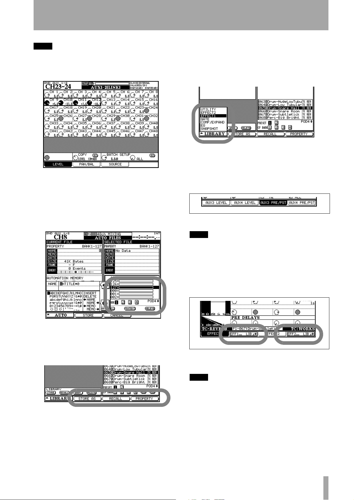
The PODs
The DM-3200 has four encoder/key combinations
(referred to as PODs) below the display. The func-
These are the PODs, which are located immediately
below the display, and the 16 encoders, located above
the channel strips.
tion of these pods varies according to the current
screen display.
Figure 2.3: POD controls
Very often, in a screen with many controls displayed,
the up and down cursor keys are used to move a highlighting box around the screen. These boxes highlight a maximum of four on-screen rotary controls,
which are then controlled by the corresponding POD
18 TASCAM DM-3200 Owner’s Manual
encoders (immediately below the on-screen controls).
Note also the contrast control to the right of the
PODs.
2 – Basic operational concepts : Special controls
TIP
You can change between a white on black display
and a black on white display by using the ALT +
FLIP key combination.
Figure 2.4: POD knobs used in a multi-control
screen
POD knobs are also used on some screens to make a
selection from a list. In these cases, the screen shows
what POD knob should be used to change the selection:
Other screens may use them as buttons which display
a pull-up list of options. When the list is shown, the
appropriate POD encoder, or the main dial, is used to
navigate through the list, and the POD key or
ENTER
key is used to confirm the entry.
Figure 2.7: POD 1 used with a pull-up menu list
The POD keys may also be used to select “subscreens” from within a major heading. In this case,
simply pressing the appropriate POD key jumps to
the next screen: as shown on the “tag”:
Figure 2.8: POD keys used to select sub-screens
Figure 2.5: POD knob 4 used as list selector
The POD keys are often used as soft keys to perform
an action, as shown on the bottom of the screen (onscreen buttons).
Figure 2.6: POD keys 2 through 4 used as soft keys
TIP
As well as using the POD keys to switch between tabbed
pages, you can also make repeated presses of the key
that was used to bring up the screen (with the
indicator lit if necessary) to change between these
pages.
ALT
The POD keys may also be used to jump to another
screen with a different function.
Figure 2.9: POD keys 2 and 4 used to jump to
other screens (library screens)
TIP
The POD knobs change values fairly coarsely, but be
pressing and holding the
unit), the POD knobs can be used for fine adjustment.
This behavior can be changed (see “Encoder behavior”
on page 23 below).
SHIFT
key (to the left of the
TASCAM DM-3200 Owner’s Manual 19
2 – Basic operational concepts : Encoders
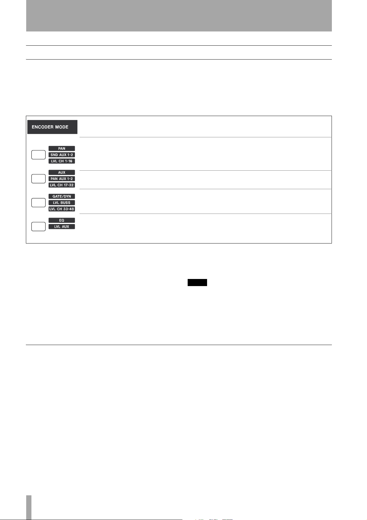
Encoders
The 16 rotary encoders at the top of each channel
have a number of functions, which are selectable
using the four keys below the dial. There are three
settings for each key, depending on whether the key
is pressed alone, or with the
the left of the DM-3200, above module 1).
SHIFT or CTRL key (at
Key pressed alone
Pan position in stereo mode(L-R
pan in surround) for the selected
fader layer
Aux sends (selected channel)
Dynamics settings (selected
channel)
EQ settings (selected channel)
Figure 2.10: Encoder functions
a. When Aux 1 and 2 are linked. Aux 1 level when they are unlinked.
b. When Aux 1 and 2 are linked. Aux 2 level when they are unlinked.
With SHIFT key With CTRL key
Aux 1–2 send level (selected fader
a
layer)
Aux 1–2 send pan position
(selected fader layer)
Buss levels Channel 33–48 levels
Aux send levels —
As you can see, by using these keys, you can view
and set the levels of channels, busses, and aux sends,
even when you are not in that particular fader layer.
Also, the channel aux send, dynamics processor and
EQ setting modes are useful for convenient viewing
and setting of a number of channel parameters at
once.
Channel 1–16 levels
b
TIP
If you are using aux sends 1 and 2 as a studio cue feed,
the
SHIFT
options provide a quick and easy way to set
up the cue mix.
Channel 17–32 levels
Encoder mappings
The following table provides a reference to the use of
the encoders in the different modes:
Pan mode Encoders 1 through 16 pan channel
modules 1 through 16 in the active fader layer (i.e.
they pan the channel whose fader is below the
encoder).
Aux mode Encoders 1 through 8 set the corre-
spondingly-numbered aux send levels for the
selected module.
20 TASCAM DM-3200 Owner’s Manual
GATE/DYN dynamics processor mode
Encoders 1 through 6 control gate parameters: 1=
threshold level; 2= gate range; 3 = attack time; 4 =
hysteresis level; 5= hold time; 6 = decay (release)
time.
Encoders 9 through 13 control compressor/expander
parameters: 9 = threshold level; 10 = compression
ratio; 11 = attack time; 12 = release time; 13 = output
level.
2 – Basic operational concepts : Encoders
EQ The encoders form four groups of four encoders,
each group controlling a different band, where 1–4
control the low band, 5–8 low-mid, 9–12 high-mid,
and 13–16 high.
Within each band, the first encoder (1, 5, 9, 13) controls gain; the second (2, 6, 10, 14) controls the frequency of the EQ band; the third (3, 7, 11, 15)
controls the Q; and the fourth (4, 8, 12, 16) controls
the band type.
SND AUX 1–2 Encoders 1 through 16 control the
level of the aux send to 1 and 2 from the channel
module immediately under the encoder when aux 1
and 2 are linked. When they are unlinked, they control the aux 1 send level.
PAN AUX 1–2 Encoders 1 through 16 control the
pan level of the aux send to 1 and 2 from the channel
module immediately under the encoder aux 1 and 2
Reading the encoder indicators
The encoder indicators change their pattern, depending on the parameter being controlled by the encoders.
are linked. When they are unlinked, they control the
aux 2 send level.
LVL BUSS The 16 encoders control the levels of the
correspondingly-numbered busses.
LVL AUX Encoders 1 through 8 control the master
levels of the aux sends.
LVL CH 1–16, 17–32, 33–48 Encoders 1
through 16 control the fader levels of the modules in
the fader layer selected by the
CTRL + ENCODER
key combination.
NOTE
For the BUSS, AUX and CH level settings, the encoders
may be set to control the same modules as the current
fader layer. In this case, turning the encoder will move
the fader, moving the fader will be reflected by the
encoder indicators.
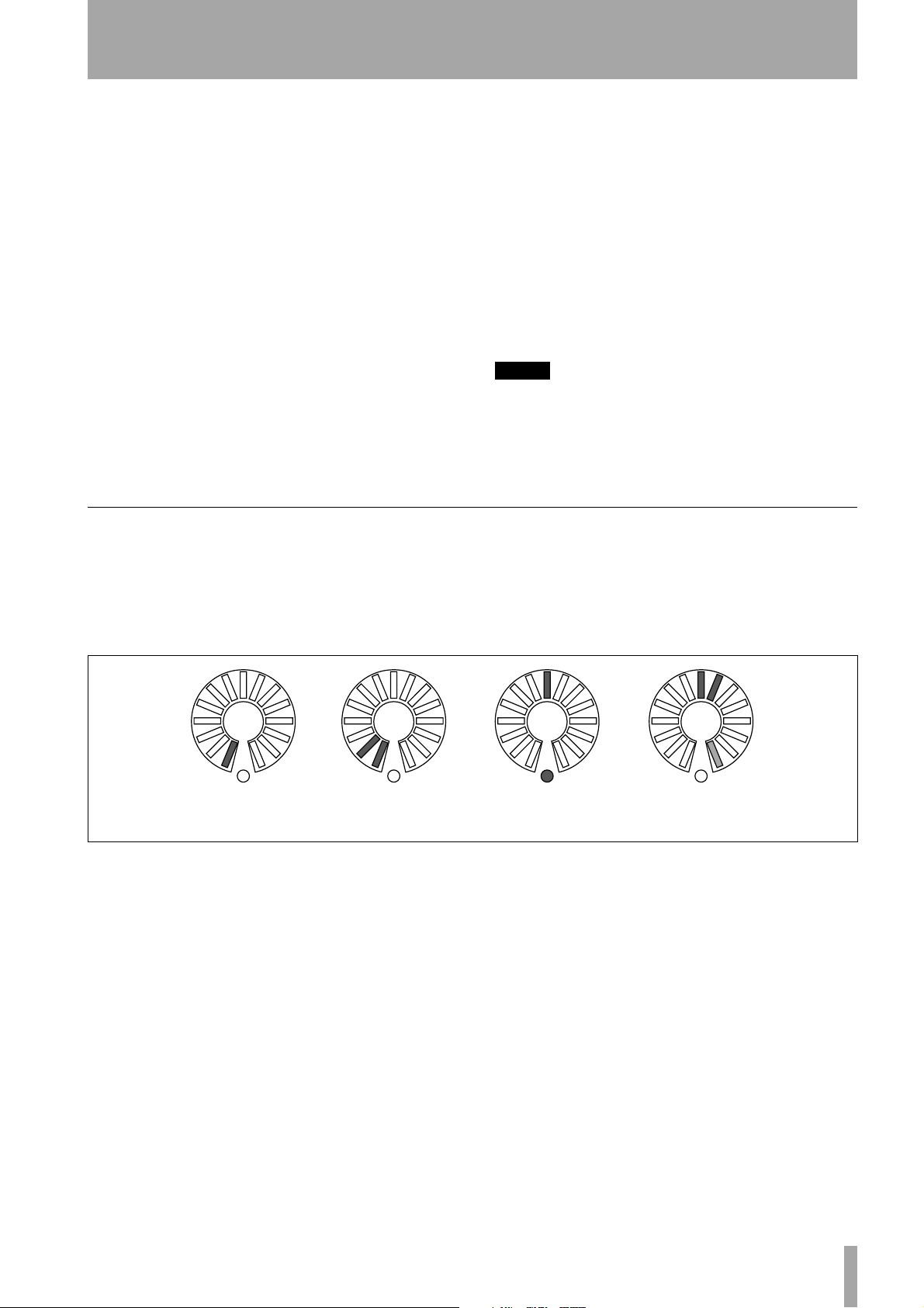
Pan settings When the PAN key is pressed, the
encoders control the panning of the channels/busses
associated with the fader (not in surround modes).
Hard left A little less hard
left
Figure 2.11: Encoders in pan mode
Note how the slight pan away from center half-lights
the indicator at the end of the circle. This helps to
indicate the fact that the pan position is not centered,
When the encoders are in pan mode, the indicator
patterns are as shown here.
Centered A little to the
right
even when the line of sight to the center indicator is
blocked by the encoder knob.
TASCAM DM-3200 Owner’s Manual 21
2 – Basic operational concepts : Encoders
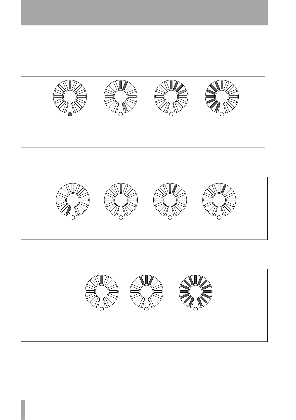
EQ settings The EQ key assigns the 16 encoders
to control the 4-band EQ for the module selected
with the
its gain, frequency, Q and type controlled by the
encoders as shown by the labels under the encoders.
The second encoders of each band in EQ mode show
the frequency of the band in the following way:
SEL keys. Each of the four bands may have
No cut or boost Slight boost (note
lower indicator is
now off)
Figure 2.12: Encoders in EQ gain mode
The first encoder in each band is used to control the
gain, the indicators are used as below. “Half-steps”
are indicated by dimmed indicators. Note also the
slight boost and cut settings, which give an indication, even when the venter is hidden by the control
knob.
A little more boost
(three indicators
now lit and
one half-lit)
Full cut
Lowest frequency Middle of the
range
Figure 2.13: Encoders in EQ frequency selection mode
The third encoders of each EQ band are used to control the Q (bandwidth), as shown here:
High Q value
(minimum band-
width)
Figure 2.14: Encoders in frequency Q adjustment mode
A little wider Minimum Q
A little higher
than middle
(widest band)
A little higher
again
22 TASCAM DM-3200 Owner’s Manual
2 – Basic operational concepts : Encoders
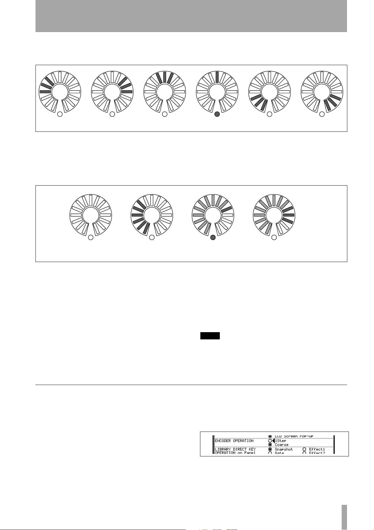
The fourth encoders of each band are used to set the
type (peak, notch, shelf, etc. of the band. An EQ band
Low shelf High shelf Peak Notch HPF LPF
Figure 2.15: Encoders used to make frequency band filter type selections
Module levels and AUX sends The level is
displayed up to the nominal level, and the nominal
level is marked by the lower indicator lighting with
all indicators up to the nominal position half-lit.
may have various options relating to the type of filter,
and the encoders reflect this:
Levels above the nominal are shown by additional
segments above the nominal segment lighting, and
those below the nominal position changing to half-lit
status, as shown in the illustration here.
Full cut Below nominal
(0dB)
Figure 2.16: Encoders used to make module level and aux send adjustments
If the encoders are “flipped”, the position of the
channel faders is represented in the same way as for
aux sends.
Dynamics settings These are typically “rotary”
settings, with the higher levels lighting more segments.
One exception to this is the output level from the
compressor/limiter, which lights the center indicator
(and bottom center indicator) at a 0 dB setting (no cut
or boost). Cuts and boots light indicators to the left
and right of the center, respectively.
Encoder behavior
Typically, the encoders, as well as the PODs, change
values several steps at a time. To change the resolution of these controls, so that they change only one
step at a time, press and hold the
extreme left of the unit) while turning the encoder.
SHIFT key (at the
Nominal (0dB) Above nominal
level
The FLIP key The FLIP key exchanges the func-
tions of the faders and the encoders, allowing the
touch-sensitive faders to be used for automating tasks
that might otherwise be performed by the encoders.
When this key is pressed, the faders automatically
move to reflect the new values assigned to them.
TIP
When setting up a cue mix on aux sends 1 and 2, for
example, you can use the faders for this, while still
keeping an eye on the main level settings (on the
encoders).
Use the cursor keys to move down in the
screen to the
you to select either
ENCODER OPERATION item, which allows
1Step (fine) or Coarse (multi-step)
as alternatives for the unshifted mode.
OPTION
However, there is an option allowing this behavior to
be changed so that the unshifted behavior makes fine
adjustments while the shifted behavior makes coarse
adjustments.
With the
ALT indicator lit, press key 2 (OPTION).
Figure 2.17: ENCODER OPERATION menu item
Press
ENTER to select one of these options.
TASCAM DM-3200 Owner’s Manual 23
2 – Basic operational concepts : CF cards
CF cards
Make sure that you have a CF card with sufficient
space on it to hold the project (one with at least
32MB, such as the one supplied with the DM-3200,
is recommended).
The DM-3200 does not retain unsaved project data
when the power is turned off. Always save project
data before turning off the DM-3200. See “Shutting
down the DM-3200” on page 25. The capacity of the
card determines the number of projects that can be
stored on it (there is a maximum of 128 projects that
can be stored on one card).
The size of a project depends on the number of
library entries, and the amount and complexity of the
automation data which forms part of the project.
Insert the card into the CF slot, pin socket edge first,
and the maker’s label towards the display (there is
often an arrow printed on the card which should
Formatting a new card
Cards must be prepared before use (including the one
supplied with the DM-3200). Once formatted by the
DM-3200, the card is formatted in FAT16 format,
allowing it to be backed up easily to a personal computer fitted with a CF card reader.
1 Enter the
TEM
UTILITY key until this page appears):
UTILITY screen, and jump to the SYS-
page (you can continue pressing the
match the arrow printed on the DM-3200’s top
panel).
To eject a card, remove the TASCAM card cover, and
press the square eject button just below the card slot.
CAUTION
To avoid possible data loss or corruption, we strongly
recommend that you only remove cards while the DM3200 is turned off. No physical damage will be caused to
either the unit or the card if you insert or remove cards
with the power turned on, though.
Note that the TASCAM card slot cover may prevent you
from seeing whether a card is actually properly inserted
or not. Always make sure the card is properly inserted
after the mixer has been transported, or the eject button has accidentally been touched. We recommend
keeping the card cover in place at all times, to avoid
dust etc. contaminating the card slot contacts.
4 One more popup appears, reminding you that
the data on the card will be erased. Press
ENTER to continue with the format operation.
As the card is being formatted, a popup
appears.
NOTE
As this popup reminds you, the power to the DM-3200
should not be turned off while the formatting operation is taking place, otherwise the card will probably be
unreadable.
Figure 2.18: Formatting a CF card
2 Move to the
the
ENTER key to press the on-screen FORMAT
CF CARD FORMAT section, and use
button.
3 A popup appears asking if you are sure you
want to format the card. Press
ENTER to con-
tinue (at any point before formatting starts,
you can press a cursor key to exit).
24 TASCAM DM-3200 Owner’s Manual
• When the card has been formatted, a Completed
popup appears briefly. The card can then be
used.
• A failure in the formatting produces a message
inviting a retry. If a card cannot be reformatted after a number of attempts, it is probably
faulty, and you are advised not to use this card
with the DM-3200.
Note that this screen also provides a number of other
features.
• You can jump from here directly to the project
management (see “About projects and libraries” on
page 26) or the library management screens (see
“Library management” on page 30).
• The DM-3200 system date and time can be set here
(see “Setting the date and time” on page 27).
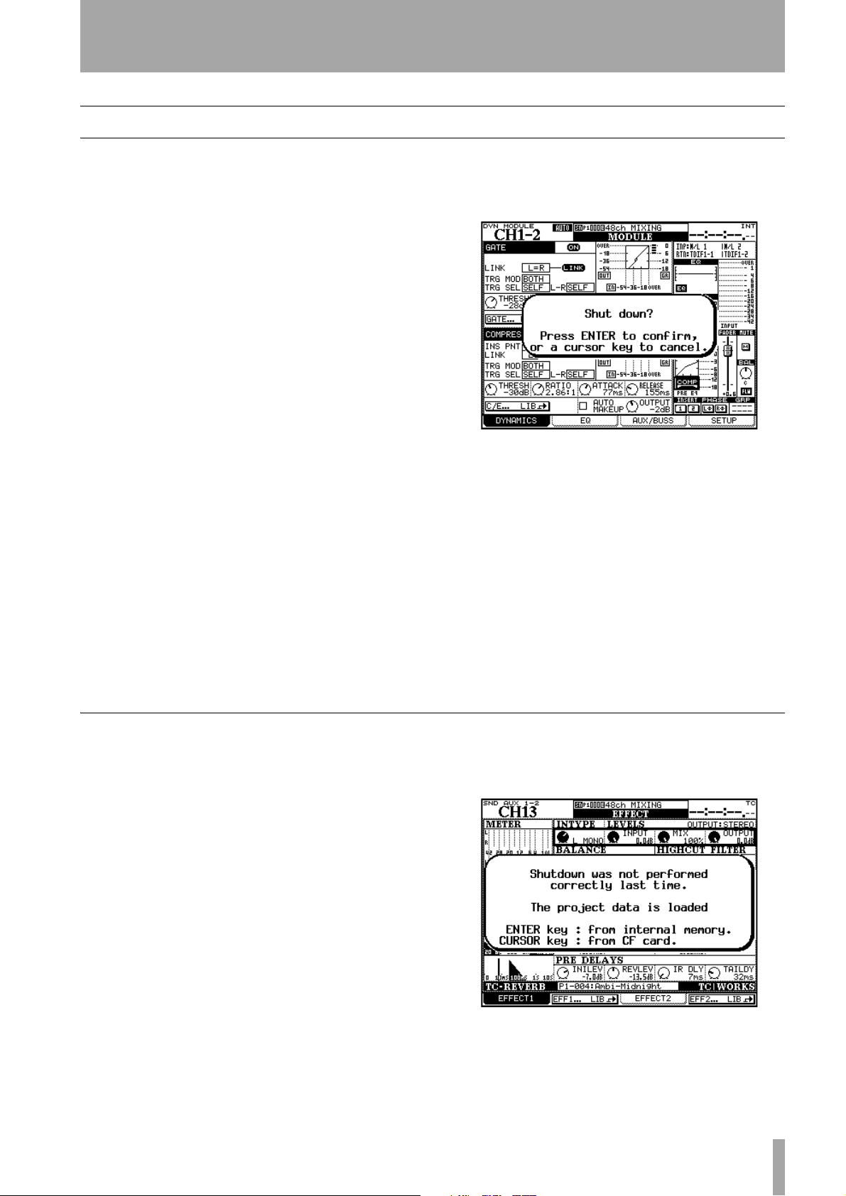
2 – Basic operational concepts : Shutting down the DM-3200
Shutting down the DM-3200
IMPORTANT CAUTION!!!
projects (automation, library entries, etc.) is not automatically stored on the card. If you turn off the DM3200 without having shut down the DM-3200 properly,
YOU MAY LOSE ALL YOUR DATA NOT STORED TO A
PROJECT SINCE THE LAST SAVE!
As when you work with computers, we strongly recommend that you save your project data to card frequently
to avoid any possible data loss.
Data associated with
How to shut down the DM-3200 In order to
shut down the DM-3200:
1 Press and hold the
side of the surface–
SHIFT and CTRL keys (left
GLOBAL section).
2 While holding down the key, press the
ALT key
of the number keypad.
Figure 2.19: Shutting down the DM-3200
3 A popup message (Figure 2.19, Shutting down
the DM-3200)appears. Press
ENTER to con-
tinue with the shutdown, or any of the cursor
keys to cancel the operation.
4 When the all the data associated with the
project has been saved, the screen shows an
appropriate message. Use the switch on the
rear panel to turn off the DM-3200.
Starting up the DM-3200
When you power down the DM-3200 after working
on a project, the project is automatically loaded, if
the CF card containing that project is inserted (a message appears on screen at the completion of the
project load).
See “About projects and libraries” on page 26 for
more details about how the DM-3200 uses projects
and libraries to manage and store data.
If the CF card is not inserted, or if a different (or
unformatted) CF card has been inserted, an appropriate message is displayed (asking if you want to format a blank card, for example).
If you do not shut down the DM-3200 as described
above before powering it down, when you next
• Alternatively, to reboot the DM-3200 without
turning it off and on again, use the
STOP + PLAY key combination.
ALT +
power it up with the project CF card installed, the
screen shows a message warning you:
Figure 2.20: Powering up the DM-3200 with no previous
shutdown
TASCAM DM-3200 Owner’s Manual 25
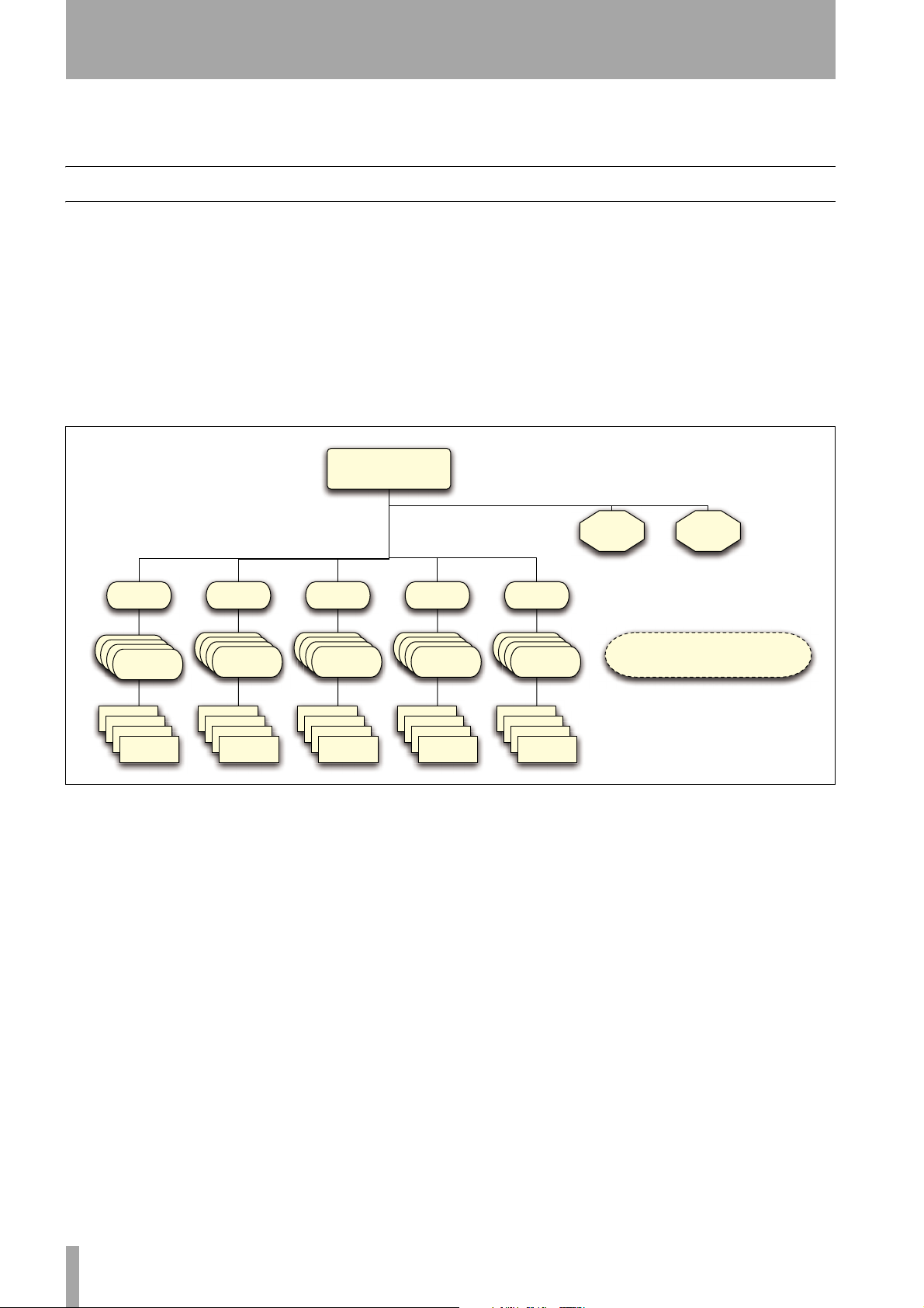
2 – Basic operational concepts : About projects and libraries
Pressing ENTER will reload the last data which was
in the internal memory (the “resume data”), and
About projects and libraries
As mentioned earlier, the DM-3200 uses projects to
store settings.
Projects contain system information, automation and
routing information associated with a project, making it easy to return to a previous state when a project
has to be conducted over more than one session.
When a new project is created, any of the following
data from a previous project may also be associated
Project
pressing a cursor key will load the project, ignoring
any changes since the last project save.
with it (it is possible to pick and choose from this
list):
• System data
• Snapshot (scene) data library
• EQ setting library
• Compressor/expander setting library
• Gate library
• Either or both of the effect libraries.
• Effect setting libraries
Automation
data
Settings
data
Snapshot EQ
CF Banks
CF Banks
CF Banks
1-4
CF Banks
1-4
1-4
1-4
Slot 1-128
Slot 1-128
Slot 1-128
Slot 1-128
(x4)
Slot 1-128
CF Banks
CF Banks
CF Banks
1-4
CF Banks
1-4
1-4
Slot 1-128
Slot 1-128
Slot 1-128
1-4
(x4)
Comp/
Exp
CF Banks
CF Banks
CF Banks
1-4
CF Banks
1-4
1-4
Slot 1-128
Slot 1-128
Slot 1-128
Slot 1-128
1-4
(x4)
CF Banks
CF Banks
Slot 1-128
Slot 1-128
Figure 2.21: Project structure
Within each project, five libraries, each divided into
four banks, contain the settings for the storable
parameters mentioned above.
Each of these banks contains 128 “slots” to hold settings (numbered from
000 to 127).
In addition, the preset bank, stored in the DM-3200’s
memory, is available for recall of presets to be used
as starting points for user settings. The effect library
has access to two preset banks.
Gate Effect
CF Banks
CF Banks
1-4
CF Banks
1-4
1-4
1-4
Slot 1-128
Slot 1-128
(x4)
CF Banks
CF Banks
Slot 1-128
Slot 1-128
Slot 1-128
Individual slots and banks may be copied between
projects after the project has been created.
Projects are stored on easily-transportable standard
Compact Flash cards, allowing projects to be tracked
in a project studio, and mixed and produced in a
larger facility, for example.
Projects are date-stamped automatically (the DM3200 contains a battery-backed clock) which helps
you keep your work organized.
1-4
CF Banks
1-4
1-4
1-4
Slot 1-128
(x4)
Libraries
Each library in each project also has access
to the appropriate preset bank (RAM).
There are two preset banks for the effects.
26 TASCAM DM-3200 Owner’s Manual
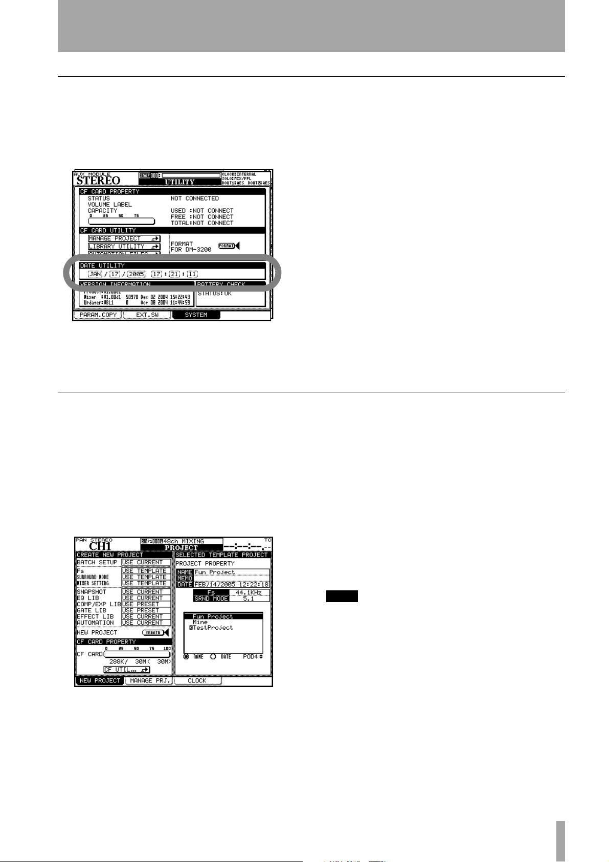
2 – Basic operational concepts : About projects and libraries
Setting the date and time
To set the date on the DM-3200, follow the steps
below:
3 Use the cursor and dial to set the date and
time.
1 Enter the
SYSTEM page:
Figure 2.22: Setting the date and time
2 Move the cursor to the
UTILITY screen, and jump to the
DATE UTILITY section of
the screen,
Creating a new project
When creating a new project, the project can be created from scratch, with manually selected sampling
frequency, surround mode and mixer settings, taking
the settings from a selected prior project that acts as a
template, from preset library settings, or from the
current settings.
1 With the
that the
ALT indicator lit, press PROJECT so
NEW PROJECT page is shown:
Note that the month is a three-letter abbreviation of the English month name (
APR, MAY, JUN, JUL, AUG, SEP, OCT, NOV, DEC) and
JAN, FEB, MAR,
the hours are set in 24-hour (“military”) format.
4 When you have set the values, press
ENTER.
The DM-3200 shows a confirmatory pop-up
message (
Date change was applied).
The calendar in the DM-3200 takes account of the
different month lengths, including leap years (up to
and including the year 2096—you may want to consider an upgrade after that time!).
More seriously, the clock is backed up by the DM3200’s internal battery. This battery should last for
several years. In the event of the battery running low,
(you can use the
OPTION/PREFERENCES screen to
check), consult your TASCAM supplier.
Use POD 4 to select an existing project on the
card to use as a template from which settings,
etc. can be copied to the new project.
3 You can use the current settings, preset set-
tings or select the settings from the template
using the wheel. Press
ENTER to confirm these
settings.
4 Use the cursor keys to select the options which
include using the current settings, the preset
settings, and the project selected at the right of
the screen that can be used a a template. Press
ENTER to confirm these settings as well.
Figure 2.23: The NEW PROJECT page
2 To set up a new project from scratch: set the
current sampling frequency and surround
mode for the project in the top left sections of
the screen.
TIP
To set all options as
the
BATCH SETUP
CURRENT, TEMPLATE
at the top left as a short cut.
or
PRESET
, use
5 Move the cursor to the on-screen CREATE but-
ton and press
ENTER, following instructions
on screen until the project is created.
Using a template Alternatively, if you already
have projects stored on the card, you can select one
of these to be used as a template. This is useful if
your facility regularly handles a certain type of
project with similar settings, as it allows you to set up
the DM-3200 with known parameters and to maintain consistency between projects.
TASCAM DM-3200 Owner’s Manual 27
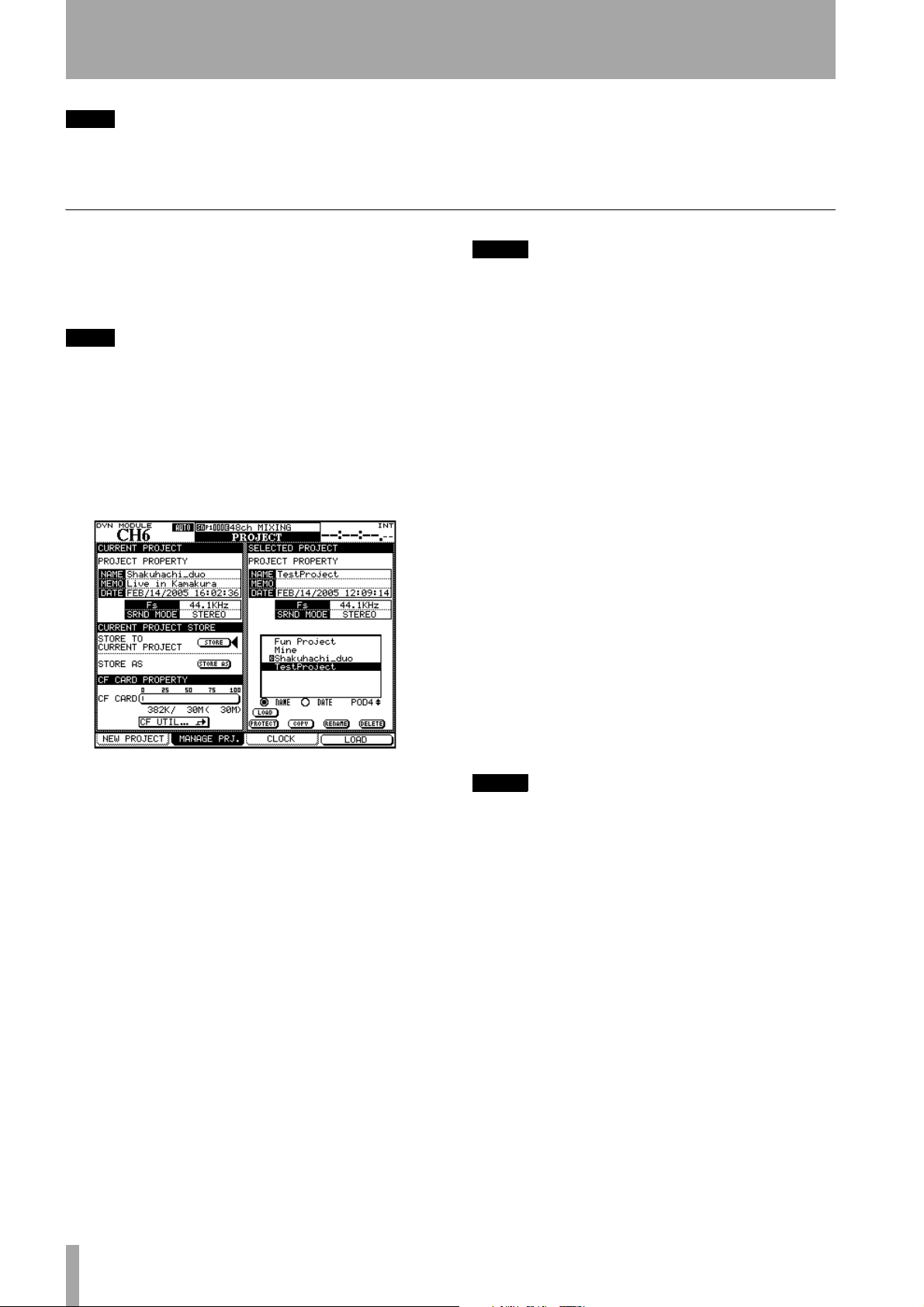
2 – Basic operational concepts : About projects and libraries
TIP
Use the radio buttons
able projects by their name (alphabetic order) or the
date of creation.
Managing projects
Projects may be deleted, renamed, etc. as well as
being copied (this last option allows you to keep different versions of the same basic project, with different EQ settings, library entries, etc.).
TIP
You can also use the software on a computer to read
the data stored on the CF card, back it up to the computer, and save it to another card. Consult the documentation of the software to find out how to do this.
Use the MANAGE PRJ. screen (press the PROJECT key
with the
manage the and card-stored projects:
ALT indicator lit until this screen appears) to
NAME
and
DATE
to sort the avail-
NOTE
The default internal project when loaded does not
allow the storage of automation, or the storage or
recall of library entries—its main function is to serve as
a blank template for a card-stored library rather than as
a working project.
Copying a project This action takes the high-
lighted project and creates a new project based on it.
When the on-screen
rename popup appears with a name and comments
based on the source project. See “Naming library
entries” on page 32 for details of how to enter and
edit names.
COPY button is pressed, the
Figure 2.24: The project management page
The currently-loaded project is indicated by an
inverted
C character by its name.
Use the POD 4 encoder to scroll through the list of
available projects.
Loading a project Use the POD 4 key as a short-
cut key (
the cursor keys to move the cursor to the on-screen
LOAD button and press ENTER.
A popup message briefly appears while loading the
project, and also when the load process is completed.
LOAD) to load the highlighted project, or use
Rename the project with a unique name (duplicate
names are not allowed, and a popup message will
inform you if you try to use an existing name) and
when you are finished, press the on-screen
CANCEL cancels the copying process).
ton (
STORE but-
Deleting a project Move the cursor to the
project to be deleted and press the on-screen
button.
A popup appears asking if you are sure you want to
delete the project. Press
ENTER to delete, or a cursor
key to cancel the delete process.
NOTE
Remember that deleting a project also deletes all the
custom library entries (snap shot, effect and dynamics
processor settings, etc.) associated with the project.
Only delete the project if you are certain that you do
not want any of the project data any more.
DELETE
Renaming a project This is very similar to the
copy procedure (see above) where the on-screen
RENAME button is pressed to provide a new unique
name for the project (as described in “Naming library
entries” on page 32).
In addition to these facilities named above, there is
an on-screen button that allows a direct jump to the
CF card maintenance screen, allowing formatting of
a card, etc.
28 TASCAM DM-3200 Owner’s Manual
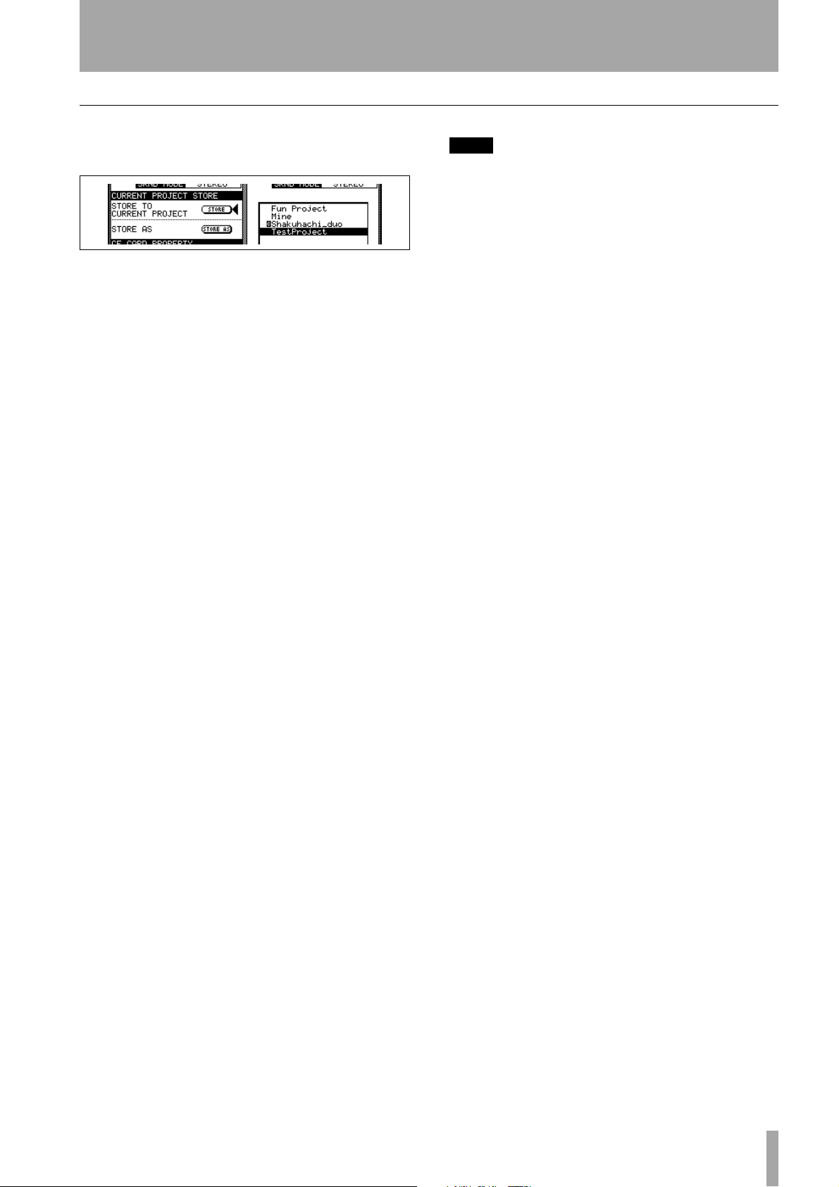
2 – Basic operational concepts : About projects and libraries
Saving project data
• From the MANAGE PRJ. screen, move the cursor
to the on-screen
Figure 2.25: Storing a project
• Press
ENTER to store the current project set-
tings. Appropriate popup messages appear,
finishing with “
tions are complete.
STORE button.
Completed” when all save opera-
TIP
Get into the habit of doing this at critical points in your
project.
You can also use the STORE AS button to bring up the
naming panel (see “Naming library entries” on
page 32), allowing the current project settings to be
stored under a different name (similar to Save As...
on many computer programs).
TASCAM DM-3200 Owner’s Manual 29
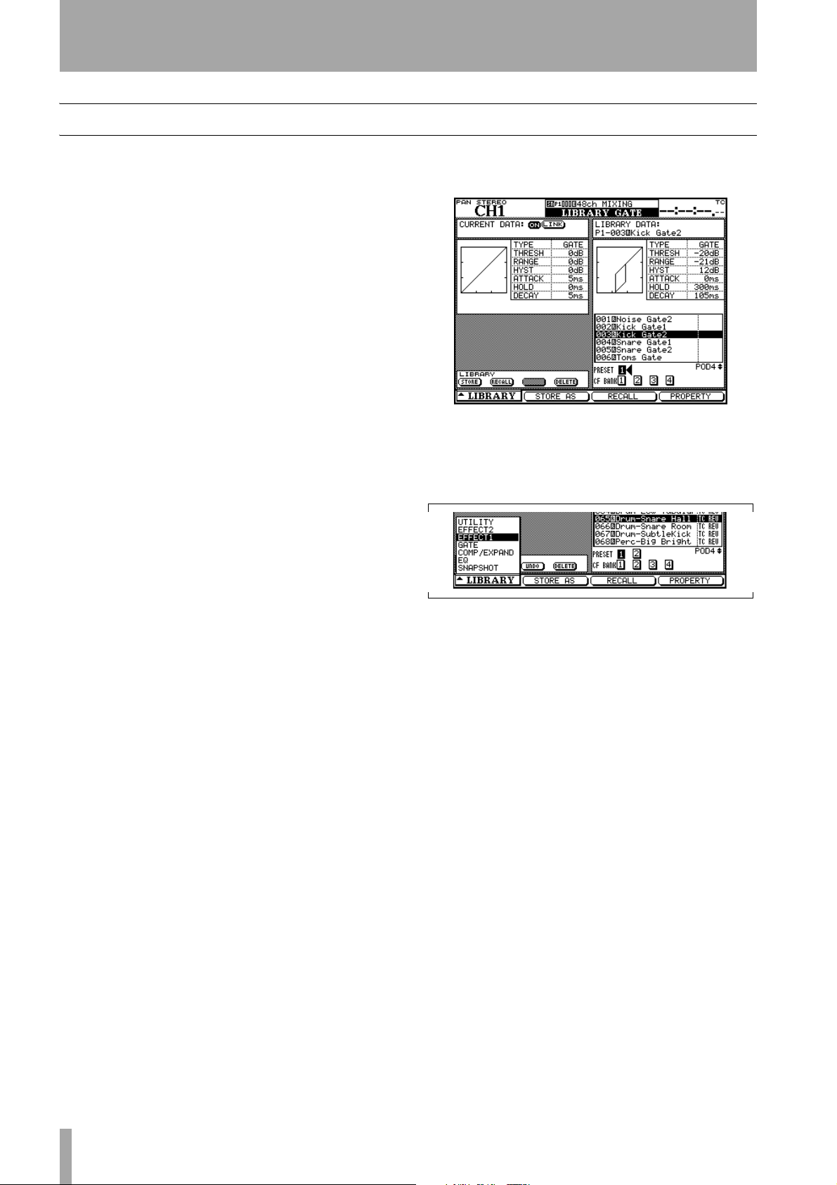
2 – Basic operational concepts : Library management
Library management
The following libraries are available within each
project on the DM-3200 for storing and recalling
commonly-used settings:
• Snapshots (scene memories)
• EQ settings
• Compressor/expander settings
• Gate settings
• Effect settings (for internal effects 1 and 2)
Up to four card-stored banks of each library type are
available in each project. These banks are independent of each other and independent of the banks in
other projects.
It is, of course, possible to copy library entries (or
entire banks) between projects, as well as using existing projects as templates, allowing favorite effect settings, for example, to be used throughout a group of
projects.
There is also an internal bank, containing read-only
preset settings, which can be accessed by all projects.
In each bank, there may be up to 128 entries. The
entries in the internal banks comprise read-only presets, which may be used unchanged, or recalled and
used as the basis for original settings.
Library entries may be named and are automatically
time-stamped, to provide a reference for just when
and why a particular effect or setting was created.
Management of the library banks and the library
entries contained in them is done from within a special utility screen accessed from a pull-up menu.
Note that all libraries are very similar in their basic
operation, and differ only in details. If there are any
specific differences relating to an individual library,
they are described in the appropriate section of the
manual.
To enter the library management screen, insert a formatted CF card (or insert a blank card and format
it—see “Formatting a new card” on page 24) and
press the
Figure 2.26: Library management (gate library
Use the POD 1 key to pull up the menu which allows
a jump to the appropriate library.
Use the POD 1 dial to highlight the required option
in the menu, and the POD 1 key or
select the highlighted option.
In most library screens, a small graphical representation of the currently-loaded setting (snapshot, EQ
setting, etc.) occupies the top left of the screen, while
the top right part of the screen is used to show a corresponding representation of the currently highlighted library entry.
LIBRARY key:
shown as example)
Figure 2.27: Library selection pull-up menu
ENTER key to
Using library banks Select the bank within the
current project by using the cursor keys to highlight
PRESET or CF BANK to be used, and pressing
the
ENTER.
30 TASCAM DM-3200 Owner’s Manual
This bank is used to recall a preset or previously
stored setting or to store the current settings.
• Current data is always stored on the left side of the
library screen, and the library data in the currentlyselected bank and slot is shown on the right.
Bank selection can also be done by pressing the
and
– keys to the left of the display in the LIBRARY
section with the
banks is selected for this purpose in the
screen.
SHIFT key pressed, when the current
OPTION
+
 Loading...