

Page 1
Digital Mixing Console
9101441500
QUICK START GUIDE
Page 2

DM-24 Quick Start Guide
This quick start guide is designed to help you with some of the common operations that
you will need to perform with the DM-24.
Naturally, it cannot pretend to be a comprehensive guide to all the facilities provided on
this console, but we hope that it will serve its purpose in getting you started with the
DM-24 and give you some idea of the capabilities of the unit.
Before you get going
There are some common sense precautions which you should note before starting to work
with the DM-24.
• Keep the DM-24 on a firm, level surface. Make sure there is enough space at the rear
for cable connections, and for ventilation.
• Avoid very hot, very cold or very humid locations for the DM-24.
• Avoid eating or drinking over the DM-24—in common with all precision electronic
equipment, the DM-24 does not work well with spilled liquid or crumbs inside the
case!
• If possible, make the area where you work with the DM-24 into a smoke-free zone.
Smoke and dust are enemies of precision electronic devices.
• When you turn on the DM-24, the faders move several times to calibrate themselves
before returning to the position when the DM-24 was last turned off. This is perfectly normal, but you should make sure that there is nothing on the top surface of
the DM-24 which will stop the faders moving, otherwise the calibration process may
be inaccurate.
• When the DM-24 is in operation, do not cover the top surface, and make sure that the
heat sink at the rear of the unit is clear.
• Always use recommended cables and connectors with the DM-24, especially when
making digital audio connections.
• Always make connections to and from the DM-24 with the power turned off to all
units. This avoids possible damage to components, as well as avoiding “thumps”,
etc. through the monitoring system.
• If anything appears to be wrong with the DM-24:
• If an error message appears, make a note of it, as well as what you were doing
immediately prior to the problem occurring.
• Read the manual. It may well contain something which is relevant to the problem
you have encountered.
• If you have Internet access, visit the TASCAM Web site for the latest product
news, etc.
• Do not attempt to repair the DM-24 yourself. Arrange for it to be examined and
repaired by TASCAM-authorized service personnel.
2
Page 3
DM-24 Quick Start Guide
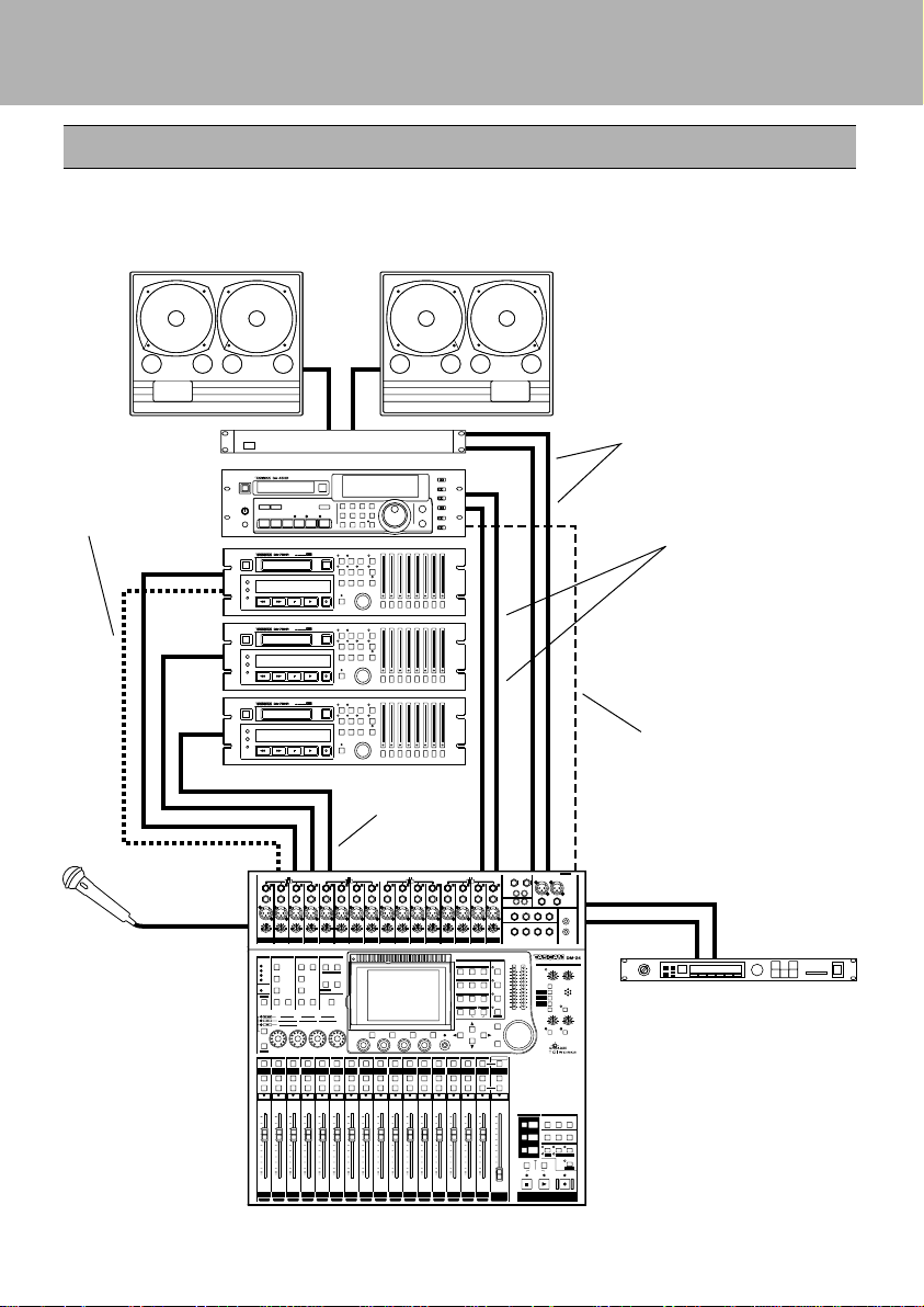
Connections to the DM-24
There are many recording devices that one might connect to the DM-24. In this scenario
we are using three DA-78HRs. Use this as a general guideline. You may not have the
same equipment, but this should help to serve as an example.
CR ROOM out to power
amp in
DTRS remote
control
S/PDIF 1 out to
DA-45HR in
Analog OUT to
2 TR return
Mic input
TDIF I/O
DA-45HR word sync
input from DM-24's
WORD SYNC OUT
Assignable sends and
returns are used to connect
with external processors
3
Page 4

DM-24 Quick Start Guide
Setting up the system
This system provides a full 24 tracks of 24-bit digital recording using three
TASCAM DA-78HRs, and mastering to 24-bit DAT using the TASCAM DA-45HR.
Points to note with this setup:
• The DA-78HR will act as the word clock master for the system. The word clock
signal is transmitted along the TDIF-1 connection to the DM-24. The DM-24
then transmits the word clock to the DA-45HR DAT recorder, using a dedicated
cable, with the DA-45HR being set to accept the word clock through this connection.
The WORD SYNC switch on the DM-24 should be in the left position (OFF/THRU).
• One cable carries eight channels of input and eight of output digital audio between
the DM-24 and the DA-78HR DTRS recorder.
Most common functions of the DTRS recorder are controlled from the DM-24
through the
with a terminator on its REMOTE OUT connector.
• The DM-24 contains two high-quality effect processors, but in this example, we are
showing how to connect an external effects processor.
The DM-24 contains its own dynamic processors. However, external dynamic
processors may be used with channel inserts or the assignable sends and returns.
• The CR outputs are used for monitoring in the control room. We have not shown any
separate studio monitoring here, but the STUDIO outputs are used to drive a studio
monitoring system (a headphone splitter box, for example)..
DTRS REMOTE CONTROL cable. The third DA-78HR must be fitted
Before switching on the DM-24, make sure that all connections have been made.
Follow the usual rule for switching on audio chains; from source to destination.
Word Sync
Then follow the steps below to set up the word sync clock on the system.
1 Set the DA-78HR to use internal word sync.
2 With the SHIFT indicator lit, press the
DIGITAL key.
The SHIFT key is a “smart” key. Press and
release quickly it to latch it on or off, or
press and hold it for longer to turn it on only
foraslongasitishelddown.
4
Page 5
DM-24 Quick Start Guide
3 If the screen at left does not appear, press
soft key 1 (the four soft keys are located
immediately below the screen).
Move the cursor to the
ENTER.
Set up the DA-45HR to accept external
4
word clock from the digital input.
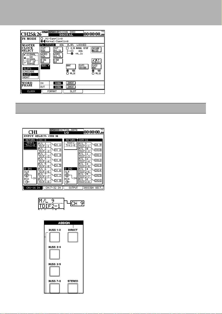
Mic/line inputs
Select mic/line inputs as the signal sources for channels 1 through 16.
1
With the SHIFT indicator lit, press the I/O
key and then soft key 1.
2 Ensure that the “patchcords” linking the sig-
nal sources to the channels, all connect the
appropriate M/L (mic/line) boxes with the
channels, as shown here.
If they do not (they are linking the lower
alternative source (return) to the channel):
Use the cursor keys to highlight the onscreen patchcord.
Use the dial to “repatch” the channel input.
Press
ENTER.
TDIF1 box and press
Press the CH 1-16 LAYER STATUS key
3
followed by the SELECT key for CH 1.
Using the assign keys to the left of the
display assign CH 1to DIRECT out. Make
sure that none of the other assignment keys
are lit. Make sure channels 2-16 are
assigned the same way.
5
Page 6

DM-24 Quick Start Guide
Outputs
We also need to set up the outputs properly for our needs. We need to make sure Direct
outs 1-8 are going to TDIF 1, Direct outs 9-16 are going to TDIF 2 and Buss 1-8 is going
to TDIF 3. While we're here we'll also assign the Stereo buss to Digital Out 1.
With the SHIFT key indicator lit, press the
1
I/O key followed by soft key #3. Use the
cursor keys to highlight the first Output
Signal field. Use the data dial to scroll to
BUSS 1-8/DIRECT 1-8 and press
ENTER. Use the same technic to change
the next field to BUSS 1-8/DIRECT 9-16.
The next field should be BUSS 18/DIRECT 1-8. Set the fourth field to
STEREO.
Tape returns
When recording on tracks 1-16 AUX 1-2 are used as the tape return path. That being
the case there are a few settings you will need to be aware of. This section will cover
those settings. Tape returns for tracks 17-24 are different and will be discussed on
another page.
1 With the SHIFT indicator lit, press the
LINK/GRP key. Press the soft key
under ST LINK. Use the cursor keys
to navigate the arrow under AUX 1 and
press ENTER. AUX 1-2 will now show
ST LINK.
2 Press the SHIFT key again so the indicator
goes out. Press the AUX 1-2 key. Press
the soft key below SOURCE. Use the
cursor keys to highlight the SETUP
section of the display. Turn the first
POD knob to change setting to RETURN.
Turn the second POD knob to change the
setting to ALL. Press ENTER. A pop up
screen will ask you to confirm by pressing
ENTER again. Do it. You'll notice that the
first 16 channels are now labeled RETURN.
6
Page 7

DM-24 Quick Start Guide
Tape returns continued
3 Press the LAYER STATUS key for CH
1-16 and press the CH 1 SELECT key.
Turn SHIFT off and press the AUX 1-2
key. Use the cursor keys to select "Aux
level fader control" at the top left of the
screen. Press ENTER to select ON. Your
Aux send levels will now be controlled by
the faders. Notice that your LAYER
STATUS key for CH 1-16 will blink.
This lets you know that you are looking
at AUX levels not CHANNEL levels. Press
the MODULE key at the left of the display
to view CHANNEL levels again. Notice
the LAYER STATUS key for CH 1-16
has stopped blinking. Now everytime you
press the AUX 1-2 key the faders will
jump to display the aux send levels.
4 Press the MASTER LAYER STATUS key.
The faders will jump to show master buss
and aux send levels. Locate the AUX 1
master fader and bring it to a unity gain
setting. In other words, push the fader to
the "0" level on the console.
5 In the control room section you'll need to
choose AUX 1-2 as your monitoring
source. Now set your control room volume
to a respectable level. Press the CH 1-16
LAYER STATUS key. Now Press the
AUX 1-2 key. Your faders now represent
your tape return levels for tracks 1-16.
Use them to set the levels as you wish.
7
Page 8

DM-24 Quick Start Guide
Tape returns continued
Recording and monitoring tracks 17-24 requires different settings than tracks 1-16.
Remember that AUX 1-2 is still our tape return path for tracks 1-16. This leaves
the first 16 channels available for us to use for our input sources. For this example,
use channels 1-8 as your input channels. Use busses 1-8 to buss those signals to
tracks 17-24. Channels 17-24 will be the tape return path for tracks 17-24 however,
since we are still using AUX 1-2 as our monitoring source we need to
set up pre fader aux 1-2 send levels for channels 17-24. This will allow us to
monitor all 24 tracks simultaneously. We will not assign channels 17-24 to the
stereo buss until we are ready to mix.
1 With the SHIFT indicator lit, press the I/O
key and then press the soft key below CH
17-32 IN. Use the cursor keys to highlight
the "patchcord" of channel 17 as in the
example to the left. Turn the data dial so
that channel 17 is linked to TDIF rather
than the Mic/Line input then press ENTER.
Repeat this process for CH 18-24. Channels
17-24 are now tape returns.
2 Press the CH 17-32 LAYER STATUS key.
Press the SELECT key for CH 17. Left of
the display locate the ASSIGN buttons. Make
changes to
sure CH 17 is NOT assigned to ST, BUSS
1-8 or DIRECT OUT. Make sure the same
is true of CH 18-24. Bring faders 17-24 down.
Press the SHIFT key so the indicator goes
out. Now press the AUX 1-2 key. The
faders will jump to show the AUX 1-2 send
levels of channels 17-32. Press the soft key
under SOURCE. Use the cursor keys to
highlight the SETUP area of the display.
Turn the first POD knob to change the
value to PRE. Use the second POD knob
to change the value to 17-24 and press
ENTER. You will see a pop up screen
asking you to confirm your choice. Press
ENTER again. Aux 1-2 for CH 17-24 are
now all PRE fader. Press the soft key under
LEVEL. Now use your faders to set the
AUX 1-2 levels for channels 17-24.
8
Page 9

DM-24 Quick Start Guide
Mix Down Mode
We are now ready to make the proper settings for mix down. First we must make
channels 1-16 Tape Return channels.
With the SHIFT indicator lit, press the I/O
1
key followed by soft key #1. Use the
cursor keys to highlight the virtual patch
cable on CH 1. Use the data dial to
change it from Mic/Line to TDIF. Use
this same technic to change channels 2-16
to TDIF as well.
Assignable sends and returns
The external effect unit that we included in the setup diagram is connected using the
assignable sends and returns. In this section we will discuss how to set up the assignable
sends and returns for this function.
1
With the SHIFT key indicator lit, press the
I/O key. Then press the soft key under
ASSIGN SECT. The 4 assignable I/Os
can be used as inserts or sends and returns.
Using the cursor keys assign 1 and 2 as
SEND/RETURN. This is under the
MODE column. Under the CH SEND
column make 1 AUX3 and 2 AUX4.
Press the MASTER LAYER STATUS key.
2
The faders will jump to show master buss
and aux send levels. Locate the AUX 3
and 4 master faders and bring them to a
unity gain setting. In other words, push
the faders to the "0" level on the console.
Now with SHIFT off press the AUX 3-4
key and set your send levels as needed.
9
Page 10

DM-24 Quick Start Guide
3
Return to the CH 17-32 IN screen by
pressing the 2nd soft key. Move the
cursor to the CH 25-32 column, then use
the data dial and the ENTER key to assign
the assignable returns 1-4(ASN RTN) to
channels 25& 26 and 31& 32. You can
now pan those channels left and right,
bring their faders to unity gain and assign
these channels to the stereo buss.
Monitoring
Until now we've been using AUX 1-2 as our monitoring source. But at mix down you will
use the 2 TR IN. This is so you can monitor the signal being recorded on the DA-45HR.
There are three programable selection keys
1
in the control room section. SEL 3 defaults
to 2 TR IN. To change these assignments
press the SHIFT key so the indicator is lit
and press the MONITOR key. Use the
cursor keys to highlight AUX 1-2 by the
SEL 1 key. Use the data dial to scroll
through your choices. Press the ENTER key
to make a change.
10
Page 11

DM-24 Quick Start Guide
Channel-to-buss assignments
Making buss assignments to multiple channels is easier to do with the ASSIGN page.
Whereas individual buss assignments are easier to do with the ASSIGN KEYS on the
front panel.
With the SHIFT indicator unlit, press the
1
ASSIGN key.
Use the fourth POD control knob to browse
2
your selection choices. Choose ST(stereo
buss). Press the soft key below ALL CH
ON. Notice that this assigns ALL channels
to the stereo buss. This is a quick way to
see where all of your channels are assigned
and to make global assignments.
3
Using your LAYER STATUS keys and the
SELECT keys select CH 1. To the left of
your display screen are the ASSIGN keys.
You can make the same buss asssignments
on a per channel basis from here.
11
Page 12

DM-24 Quick Start Guide
Setting EQ in the modules
The EQ settings on the DM-24 are made using the PODs (immediately below the screen)
or the four rotary encoders to their left.
1 Press the SEL key of the channel to be
edited.
2 Press the MODULE key and then soft key 2
to jump straight to the EQ screen.
Choose one of the four EQUALIZER band
3
selection keys to begin manipulating the
frequency content of the program material on
this channel.
4 Use the graphical display at the top of the
screen to see the EQ response curve.
The EQUALIZATION ON key (to the right
of the band selection keys) turns the EQ on
and off for instant A/B comparisons.
12
Page 13

DM-24 Quick Start Guide
Snapshot recall
The DM-24 allows almost all mixer settings to be stored as part of a snapshot which can be
stored and recalled. There are also libraries available for EQ settings, for effects settings
and for dynamic processor settings.
With the SHIFT key unlatched press the
LIBRARY key. Press the soft key under
LIBRARY. A small pop up screen will let you
choose which type of snapshot you want to
recall. Choose SNAPSHOT by using the first
POD knob and the ENTER key. Your
snapshot library will now appear. Use the data
dial to choose MIXING and press the soft key
under RECALL. All of the DM-24's
parameters have now been changed to the
appropriate settings for mix down. Use the
data dial to choose RECORDING and press
the soft key under RECALL. All of the DM-
The top of the display will show you
what snapshot you're using at any given
time. To the left of the display are the
LIBRARY keys. Pressing the + or keys allows you to browse snapshots.
Pressing RECALL will load the
snapshot in the display. There is also an
24's parameters have now been changed to the
appropriate settings for tracking. A full list of
the settings in these snapshots is included in
this quick guide (Refer to page 16). Consider
these two shapshots as a good starting place.
You may need to make changes and store your
own snapshots to fit your personal needs.
option that allows you to recall a
snapshot by pressing ONLY the + or key.
13
Page 14

DM-24 Quick Start Guide
Controlling the DA-78HR
The DM-24 allows control over the DA-78HR DTRS recorder, using the built-in transport
controls, etc.
As well as this, the
DA-78HR, and other special features of the DA-78HR are also directly controllable from
the DM-24.
To set up the DM-24 to control the DA-78HR:
REC keys above the channels can also be used to arm the tracks of the
1
With the SHIFT indicator lit, press the MIDI/
key and then soft key 2.
MC
Turn the dial until the
lighted in the list at the right of the screen,
move the cursor to the
bottom of the list, and press ENTER.
Move the cursor to the left side of the screen
2
where the DA-78HR is listed.
Move the cursor to the
ENTER. This allows the transport controls
of the DM-24 to control the DA-78HR.
DA-78HR is high-
<-ADD button at t he
TRA button and press
With the SHIFT indicator lit, press the
3
OPTION key.
Press soft key 4 to bring up the SYNC/
TIMECODE screen.
Select OTHERS/ TRA Target Link (the DA78HR which has been selected as the transport target) as the TIMECODE DISPLAY
TYPE.
The timecode is received through the
REMOTE CONTROL connector.
Consult the DA-78HR documentation for
details ofhow toselect thetimecode usedfor
output.
14
DTRS
Page 15

DM-24 Quick Start Guide
Mixing Snap Shot
1. All channel EQ set to ON. Hi =10.1kHz, H.
SHELF, Gain =0dB, Hi Mid=5.04kHz, Q=1.20,
Gain =0dB, Low Mid=1.26kHz, Q=1.20,
Gain=0dB, Low=125Hz, L. SHELF, Gain=0dB.
2. All channel dynamics set to OFF.
3. Compressor settings:Threshold=-10dB,
Ration=4.00:1, Attack=53ms, Release=180ms.
4. Channels 1- 24 set to zero, 25-32 set to unity,
buss masters, aux masters and stereo buss set to
unity gain.
5. All pans set to center.
6. All channels assigned to the stereo buss.
7. Channels 1-8 should reference TDIF-1,
9-16 TDIF-2, 17-24 TDIF-3.
8. Channels 1-24 should be set to TDIF returns.
9. Channels 25-28 should be set to Effect 1 L&R
and Effect 2 L&R.
10. Channels 29-32 should be set to assignable
returns 1-4.
11. Channels 25-32 should be linked stereo pairs.
Recording Snap Shot
1. All channel EQ set to ON. Hi =10.1kHz, H.
SHELF, Gain =0dB, Hi Mid=5.04kHz, Q=1.20,
Gain =0dB, Low Mid=1.26kHz, Q=1.20,
Gain=0dB, Low=125Hz, L. SHELF, Gain=0dB.
2. All channel dynamics set to OFF.
3. Compressor settings:Threshold=-10dB,
Ration=4.00:1, Attack=53ms, Release=180ms.
4. Channels 1- 24, buss masters, aux masters set to
unity gain.
5. Channels 25-32 set to zero.
6. All pans set to center.
7. NO channel assignments (stereo, buss 1-8,
direct out.)
8. Channels 1-8 should reference TDIF-1, 9-16
TDIF-2, 17-24 TDIF-3.
9. Channels 1-16 should be set to Mic/line inputs.
10. Channels 17-24 should be set to TDIF returns.
11. Channels 25-28 should be set to Effect 1 L&R
and Effect 2 L&R.
12. Channels 29-32 should be set to assignable
returns 1-4.
13. Channels 25-32 should be linked stereo pairs
12. TDIF-1=Direct out1-8/Buss 1-8, TDIF-2=Direct
out 9-16/Bus 1-8, TDIF-3=Direct out 1-8/Buss
1-8.
13. Aux 1-6 source set to Post.
14. Aux 1-6 levels set to zero.
15. Digital stereo outputs set to 16 bit noise shaped.
16. Digital out 1 set to AES/EBU, Digital out 2 set
to S/PDIF.
17. Digital out 1and 2 reference the stereo buss .
18. Format of digital input 1-2 can be recognized
automatically.
19. All TDIF I/O set to 24 bit.
20. Assignable sends and returns all set to sends and
returns(not inserts.)
21. Insert matrix compressors should be set to
stereo buss only.
22. Effect 1 set to MONO input-Left input source
AUX 1
23. Effect 2 set to MONO input-Left input source
AUX 2
14. TDIF-1=Direct out1-8/Buss 1-8, TDIF-2=Direct
out 9-16/Bus 1-8, TDIF-3=Direct out 1-8/Buss
1-8.
15. Aux sends should be set to fader control.
16. Aux 1-2 should be linked.
17. Aux 1-2 source should be set to Return for
channels 1-16.
18. Aux 1-2 source should be set to Pre for channels
17-32
19. Aux 1-2 levels should be set to unity gain for
channels 1-24.
20. Aux 3-6 source should be set to Pre.
21. Aux 3-6 levels should be set to zero.
22. Digital stereo outputs set to 16 bit noise shaped.
23. Digital out 1 set to AES/EBU, Digital out 2 set
to S/PDIF.
24. Digital out 1and 2 reference the stereo buss.
25. Format of digital input 1-2 can be recognized
automatically.
26. All TDIF I/O set to 24 bit.
27. Assignable sends and returns all set to sends and
returns(not inserts.)
28. Insert matrix compressors should be set to
busses 1-6.
15
Page 16

DM-24 Quick Start Guide
System Default Settings
* Clock set to TDIF 1
* SETUP-Time Code, LCD screen popup, Coarse, Snapshot, OL -3dB
* PREFRENCES-Select Module Return, ST Link by Select Key, Balance Level Center 0dB,
Select Key Follows Fader Level, Fader Meter Follow, Cursor Follows EQ Band Key.
* Solo Mode Select=Mix Solo, Solo Link=OFF, Solo Type=AFL, NO Inplace solo defeat.
* SYNC/TC SETUP-Sync Source, TC IN, Fly Wheel 8 Frames.
* Word Phase=Normal IN, Normal OUT.
16
 Loading...