

Tascam DA-6400 Users Manual

D01249320A
DA-6400
DA-6400dp
Digital Multitrack Recorder
OWNER'S MANUAL
IMPORTANT SAFETY PRECAUTIONS
CAUTION: TO REDUCE THE RISK OF ELECTRIC SHOCK, DO NOT REMOVE COVER (OR
BACK). NO USER-SERVICEABLE PARTS INSIDE. REFER SERVICING TO QUALIFIED SERVICE
PERSONNEL.
The lightning flash with arrowhead symbol, within equilateral triangle, is intended to alert
the user to the presence of uninsulated “dangerous voltage” within the product’s enclosure that may be of sufficient magnitude to constitute a risk of electric shock to persons.
The exclamation point within an equilateral triangle is intended to alert the user to the
presence of important operating and maintenance (servicing) instructions in the literature accompanying the appliance.
WARNING: TO PREVENT FIRE OR
SHOCK HAZARD, DO NOT EXPOSE
THIS APPLIANCE TO RAIN OR
MOISTURE.
For U.S.A.
This device complies with Part 15 of FCC Rules. Operation
is subject to the following two conditions:
1) This device may not cause harmful interference, and
2) This device must accept any interference received,
including interference that may cause undesired
operation.
INFORMATION TO THE USER
This equipment has been tested and found to comply
with the limits for a Class A digital device, pursuant to Part
15 of the FCC Rules. These limits are designed to provide
reasonable protection against harmful interference when
the equipment is operated in a commercial environment.
This equipment generates, uses, and can radiate radio
frequency energy and, if not installed and used in accordance with the instruction manual, may cause harmful
interference to radio communications.
Operation of this equipment in a residential area is likely to cause harmful interference in which case the user
will be required to correct the interference at his own
expense.
DECLARATION OF CONFORMITY
We, TEAC EUROPE GmbH. Bahnstrasse 12, 65205
Wiesbaden-Erbenheim, Germany declare in own
responsibility, the TEAC product described in this
manual is in compliance with the corresponding
technical standards.
CE Marking Information
a) Applicable electromagnetic environment: E4
b) The average half-cycle r.m.s. inrush current
1. On initial switch-on: 2.91 Arms
2. After a supply interruption of 5s: 0.15 Arms
For the customers in Europe
WARNING
This is a Class A product. In a domestic environment, this
product may cause radio interference in which case the
user may be required to take adequate measures.
Pour les utilisateurs en Europe
AVERTISSEMENT
Il s'agit d'un produit de Classe A. Dans un environnement
domestique, cet appareil peut provoquer des
interférences radio, dans ce cas l'utilisateur peut être
amené à prendre des mesures appropriées.
CAUTION
Changes or modifications to this equipment not expressly
approved by TEAC CORPORATION for compliance could
void the user's authority to operate this equipment.
IN USA/CANADA, USE ONLY ON 120 V SUPPLY.
For Canada
THIS CLASS A DIGITAL APPARATUS COMPLIES WITH CANADIAN
ICES-003.
CET APPAREIL NUMERIQUE DE LA CLASSE A EST CONFORME A
LA NORME NMB-003 DU CANADA.
TASCAM DA-6400/DA-6400dp
2
Für Kunden in Europa
Warnung
Dies ist eine Einrichtung, welche die Funk-Entstörung
nach Klasse A besitzt. Diese Einrichtung kann im
Wohnbereich Funkstörungen versursachen; in diesem
Fall kann vom Betrieber verlang werden, angemessene
Maßnahmen durchzuführen und dafür aufzukommen.
IMPORTANT SAFETY INSTRUCTIONS
1 Read these instructions.
2 Keep these instructions.
3 Heed all warnings.
4 Follow all instructions.
5 Do not use this apparatus near water.
6 Clean only with dry cloth.
7 Do not block any ventilation openings. Install in
accordance with the manufacturer's instructions.
8 Do not install near any heat sources such as radiators,
heat registers, stoves, or other apparatus (including
ampliers) that produce heat.
9 Do not defeat the safety purpose of the polarized
or grounding-type plug. A polarized plug has two
blades with one wider than the other. A grounding
type plug has two blades and a third grounding
prong. The wide blade or the third prong are provided for your safety. If the provided plug does not fit
into your outlet, consult an electrician for replacement of the obsolete outlet.
10 Protect the power cord from being walked on or
pinched particularly at plugs, convenience receptacles, and the point where they exit from the apparatus.
11 Only use attachments/accessories specified by the
manufacturer.
12 Use only with the cart, stand, tripod, bracket, or table
specied by the manufacturer, or sold with the apparatus. When a cart is used, use caution when moving
the cart/apparatus combination to avoid injury from
tip-over.
• The apparatus draws nominal non-operating power
from the AC outlet with its POWER or STANDBY/ON
switch not in the ON position.
• The mains plug is used as the disconnect device, the
disconnect device shall remain readily operable.
• Caution should be taken when using earphones or
headphones with the product because excessive
sound pressure (volume) from earphones or
headphones can cause hearing loss.
• If you are experiencing problems with this product,
contact TEAC for a service referral. Do not use the
product until it has been repaired.
CAUTION
• Do not expose this apparatus to drips or splashes.
• Do not place any objects filled with liquids, such as
vases, on the apparatus.
• Do not install this apparatus in a confined space
such as a book case or similar unit.
• The apparatus should be located close enough
to the AC outlet so that you can easily grasp the
power cord plug at any time.
• If the product uses batteries (including a battery
pack or installed batteries), they should not be
exposed to sunshine, fire or excessive heat.
• CAUTION for products that use replaceable lithium
batteries: there is danger of explosion if a battery is
replaced with an incorrect type of battery. Replace
only with the same or equivalent type.
WARNING
• Products with Class ! construction are equipped
with a power supply cord that has a grounding
plug. The cord of such a product must be plugged
into an AC outlet that has a protective grounding
connection.
8
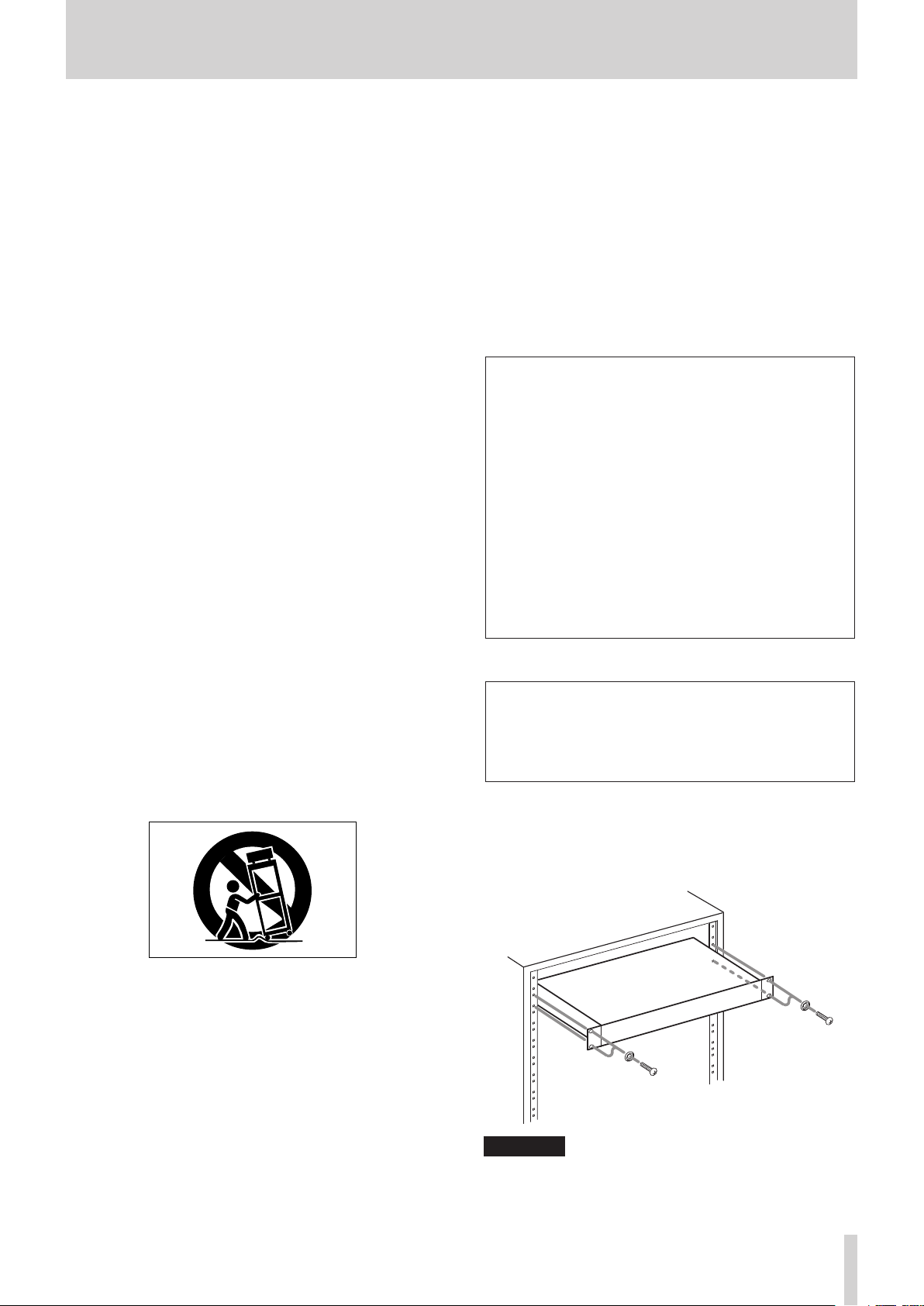
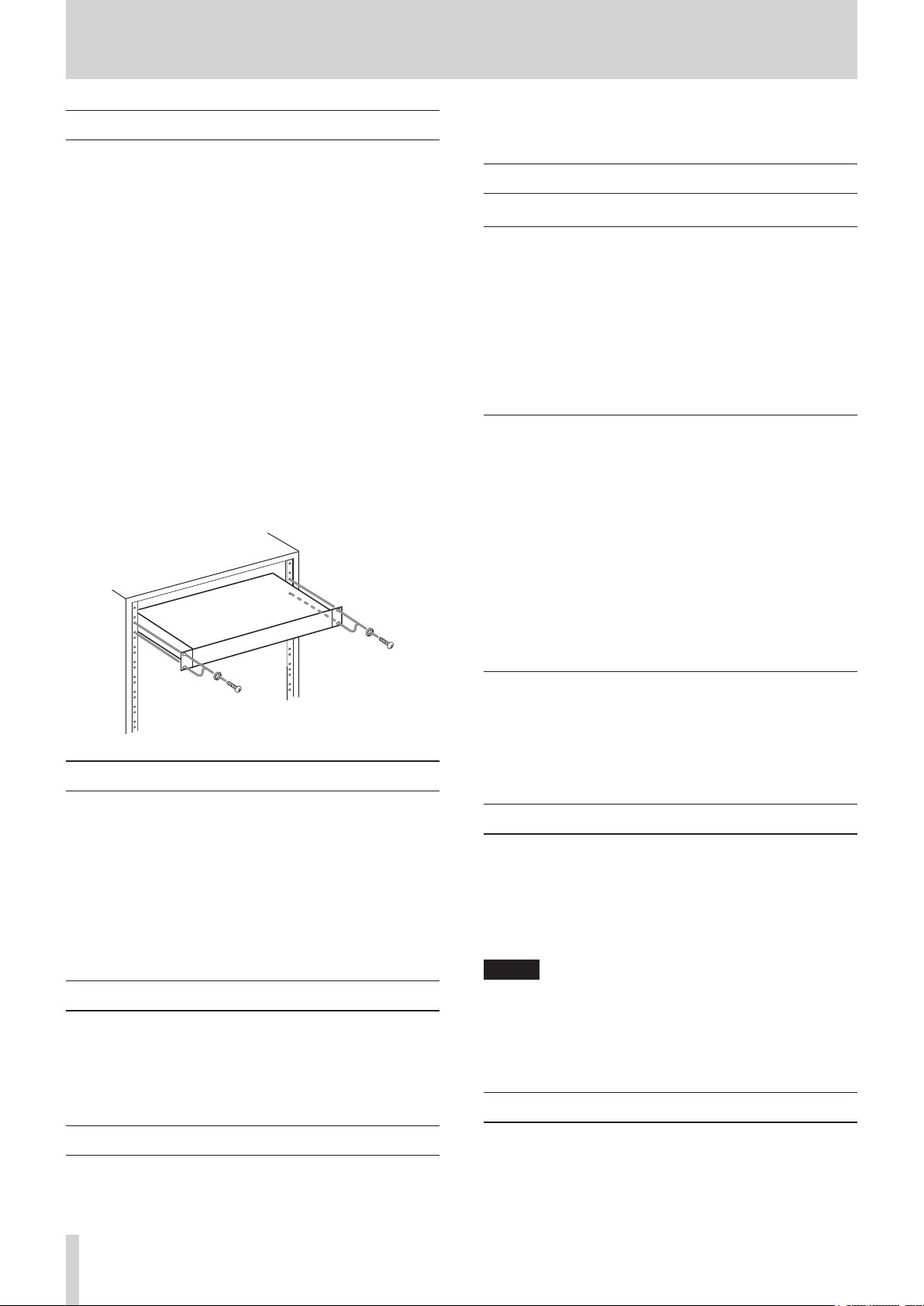
RACK-MOUNTING THE UNIT
Use the supplied rack-mounting kit to mount the unit in a
standard 19-inch rack, as shown below.
Remove the feet of the unit before mounting.
13 Unplug this apparatus during lightning storms or
when unused for long periods of time.
14 Refer all servicing to qualified service personnel.
Servicing is required when the apparatus has been
damaged in any way, such as power-supply cord or
plug is damaged, liquid has been spilled or objects
have fallen into the apparatus, the apparatus has
been exposed to rain or moisture, does not operate
normally, or has been dropped.
CAUTION
•
Leave 1U of space above the unit for ventilation.
•
Allow at least 10 cm (4 in) at the rear of the unit for ventilation.
TASCAM DA-6400/DA-6400dp
3
Safety Information
Pb, Hg, Cd
8
For European Customers
Disposal of electrical and electronic equipment
(a) All electrical and electronic equipment should be
disposed of separately from the municipal waste
stream via designated collection facilities appointed
by the government or the local authorities.
(b) By disposing of the electrical and electronic
equipment correctly, you will help save valuable
resources and prevent any potential negative effects
on human health and the environment.
(c) Improper disposal of waste equipment can have
serious effects on the environment and human health
as a result of the presence of hazardous substances in
electrical and electronic equipment.
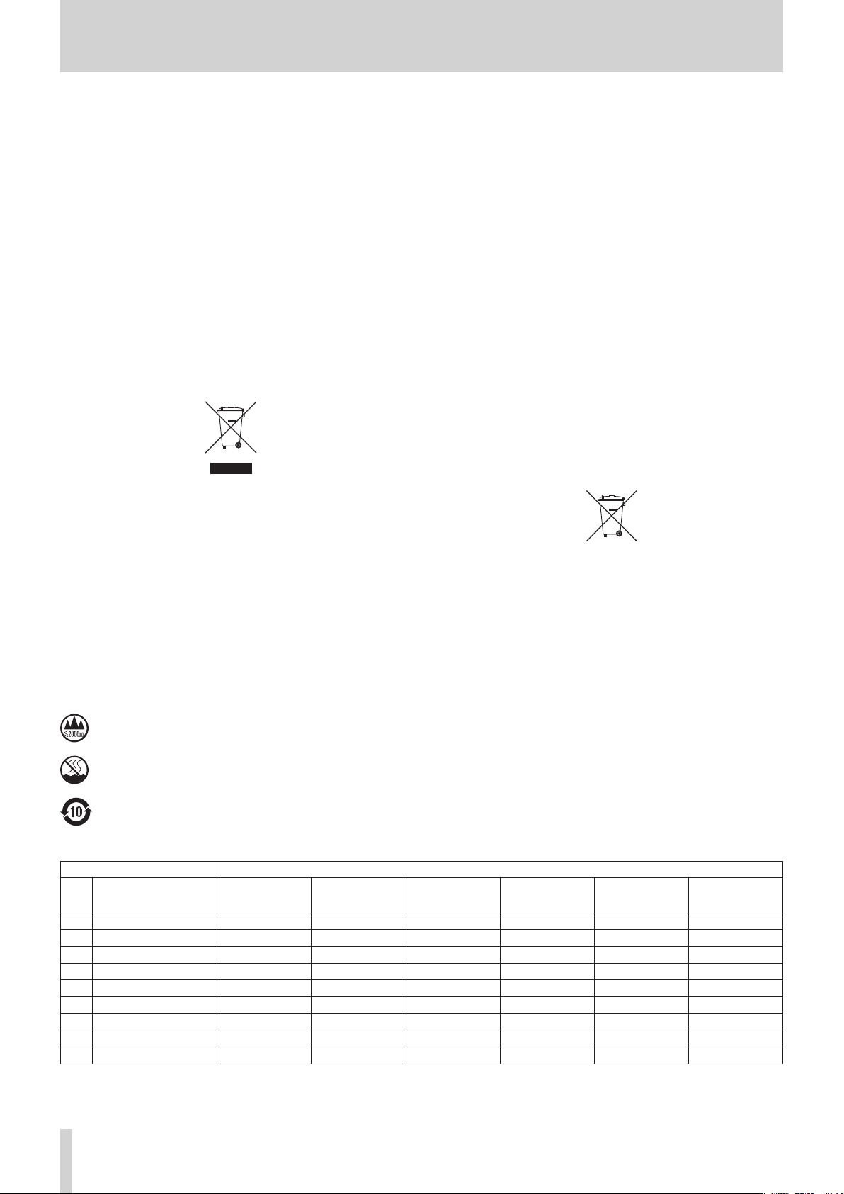
(d) The crossed out wheeled dust bin symbol indicates
that electrical and electronic equipment must be
collected and disposed of separately from household
waste.
(e) The return and collection systems are available to
the end users. For more detailed information about
disposal of old electrical and electronic equipment,
please contact your city office, waste disposal service
or the shop where you purchased the equipment.
Disposal of batteries and/or accumulators
(a) Waste batteries and/or accumulators should be
disposed of separately from the municipal waste
stream via designated collection facilities appointed
by the government or the local authorities.
(b) By disposing of waste batteries and/or accumulators
correctly, you will help save valuable resources and
prevent any potential negative effects on human
health and the environment.
(c) Improper disposal of waste batteries and/or
accumulators can have serious effects on the
environment and human health as a result of the
presence of hazardous substances in batteries and/or
accumulators.
(d) The crossed out wheeled dust bin symbol indicates
that batteries and/or accumulators must be collected
and disposed of separately from household waste.
If the battery or accumulator contains more than
the specified values of lead (Pb), mercury (Hg), and/
or cadmium (Cd) defined in the Battery Directive
(2006/66/EC), then the chemical symbols for lead (Pb),
mercury (Hg) and/or cadmium (Cd) will be indicated
beneath the crossed out wheeled dust bin symbol.
(e) The return and collection systems are available to
the end users. For more detailed information about
disposal of waste batteries and/or accumulators,
please contact your city office, waste disposal service
or the shop where you purchased them.
8
For China
“仅适用于海拔 2000m 以下地区安全使用”
“仅适用于非熱帯气候条件下安全使用”
“環境保護使用年限”
产品有毒有害物质或元素的名称及含量
机种 :DA-6400 有毒有害物质或元素
品名
1 CHASSIS 部份 ○ ○ ○ ○ ○ ○
2 FRONT PANEL 部份 ○ ○ ○ ○ ○ ○
3 螺丝部份 ○ ○ ○ ○ ○ ○
4 线材部份 ○ ○ ○ ○ ○ ○
5 PCB Assy 部份 × ○ ○ ○ ○ ○
6 电源部份 ○ ○ ○ ○ ○ ○
7 附属品部份 × ○ ○ ○ ○ ○
8 LABEL 部份 ○ ○ ○ ○ ○ ○
9 包装部份 ○ ○ ○ ○ ○ ○
○ :表示该有毒有害物质在该部件所有均质材料中的含有量均在 GB/T26572-2011 标准规定的限量要求以下。
× :表示该有毒有害物质至少在该部件的某一均质材料中的含量超出 GB/T26572-2011 标准规定的限量要求。
(针对现在代替技术困难的电子部品及合金中的铅 )
铅
(Pb)
汞
(Hg)
镉
(Cd)
六价铬
(Cr6+)
多溴联苯
(PBB)
多溴二苯醚
(PBDE)
TASCAM DA-6400/DA-6400dp
4

Contents
1 – Introduction ..............................................7
Features .................................................................................. 7
Included items .....................................................................7
Conventions used in this manual ..................................7
Trademarks ............................................................................ 7
Precautions for placement and use ..............................8
Notes about power supplies ........................................... 8
Beware of condensation ...................................................8
Cleaning the unit ................................................................. 8
Notes about SSD and HDD drives ................................. 8
Notes about media ...................................................... 8
Precautions for use ...................................................... 8
Note about formatting ...............................................8
Using the TEAC Global Site .............................................. 8
User registration .................................................................. 8
2 – Names and Functions of Parts .................9
Front panel ............................................................................9
Rear panel ............................................................................ 11
Note about the PARALLEL connector ................. 12
Home Screen ...................................................................... 12
Menu structure .................................................................. 14
Basic Menu Screen operations .....................................16
Menu operation procedures ..................................16
3 – Preparation ..............................................17
Installing an SSD/HDD drive in the case ...................17
Loading and removing SSD/HDD cases ....................17
Loading an SSD/HDD case ......................................17
Removing an SSD/HDD case ..................................17
Using the security screw ..........................................17
Connecting and disconnecting USB flash drives ..18
Installing I/O cards (sold separately) ..........................18
Turning the unit on and off (putting it in standby)
Setting the built-in clock date and time ...................19
Adjusting the brightness ................................................ 19
Preparing SSD/HDD drives and USB flash drives
for use....................................................................................19
Connecting headphones ...............................................20
Setting headphones monitoring mode .............20
Setting the lock function ...............................................21
.18
4 – Recording ................................................22
Restrictions on recording operations ........................22
Setting the master clock .................................................22
Making word/video connector settings ...................23
Setting the reference level ............................................23
Setting input monitoring ...............................................23
Setting input monitoring for specific channels 24
Making recording channel settings ...........................24
Setting the record function
for specific channels .................................................24
Setting the recording file format ................................25
Setting the file name format ........................................26
Editing text ...................................................................26
Automatically incrementing take numbers ............27
Incrementing take numbers manually ......................27
Adding marks automatically when recording ........27
Adding marks manually when recording.................28
Adding marks when recording .............................28
Setting the pause mode function ...............................28
Setting input signal routing ..........................................28
Making I/O card settings ................................................28
Settings for IF-MA64/EX
and IF-MA64/BN cards .............................................29
Timecode synchronized recording ............................29
Recording duration ..........................................................29
5 –
Working with Folders (BROWSE screen)
Opening the BROWSE screen .......................................30
Navigating the BROWSE screen ...................................30
Icons on the BROWSE screen ........................................30
Folder operations ..............................................................30
Take and file operations .................................................31
Editing folder, take and file names .............................31
Deleting folders, takes and files ..................................32
Copying folders, takes and files ...................................32
Rebuilding folders ............................................................33
Editing the start timecode of a take ...........................33
Creating new folders .......................................................33
Folder structure overview..............................................34
Folder structure .................................................................34
File name .......................................................................34
File formats ..........................................................................34
..30
6 – Playback ...................................................35
Files that can be played back ........................................35
Basic playback operations .............................................35
Playing recordings .....................................................35
Selecting takes ...................................................................35
Skipping to the previous/next take ..................... 35
Selecting takes directly ............................................ 35
Searching backward and forward ............................... 35
Setting the play mode ....................................................35
Setting the repeat mode ................................................ 35
7 – Internal Settings .....................................36
Setting the timecode .......................................................36
TC SETUP 1 page settings .......................................36
TC SETUP 2 page settings .......................................37
PARALLEL connector settings ......................................38
PARALLEL INPUT page settings .............................38
PARALLEL OUTPUT page settings ........................38
Network function settings ............................................. 39
Setting the SNTP function .............................................40
Network functions (FTP server/telnet/VNC) ........... 42
TASCAM DA-6400/DA-6400dp
5

Contents
FTP (file transfer protocol) server .........................42
Remote control (Telnet) ...........................................43
VNC (virtual network computing) ........................44
Making oscillator settings ..............................................44
8 – Mark and Locate Functions ....................45
Mark functions ...................................................................45
Adding marks .............................................................. 45
Using marks ..................................................................45
Moving to marks ........................................................45
Editing mark names...................................................46
Deleting marks ............................................................46
Deleting all marks in the current take ................46
Editing mark locations ..............................................46
Viewing mark information ......................................46
Locating to a specific time ............................................. 47
Locating before completely specifying
the time .........................................................................47
9 – Loading Files Recorded
by Other Devices .....................................48
Preparation before loading ...........................................48
Using the loaded files on the unit ...............................48
Dimensional drawings ....................................................59
Block diagrams ................................................................... 59
14 –
Important notice regarding software
Open Source License Term ............................................60
..60
10 – Data Transfer Using a Computer ..........49
Computer system requirements .................................49
Connecting an SSD/HDD to a computer ..................49
Disconnecting from a computer ..........................50
11 – Other Settings, Information Screens
and Keyboard Operations .....................51
INFO button and indicator appearance ....................51
Checking the firmware version ....................................51
Firmware update procedures ....................................... 52
Viewing media information ..........................................52
Setting peak hold time ...................................................53
Setting the meter mode .................................................53
Using a USB keyboard to operate the unit...............53
Setting the keyboard type ......................................53
Using the keyboard to input names
and values .....................................................................53
List of keyboard operations ....................................54
Setting the power redundancy check function
(DA-6400dp only) .............................................................55
Exporting/importing system backup data .............. 55
Restoring factory default settings ..............................56
12 – Troubleshooting ....................................57
13 – Specifications ........................................58
General .................................................................................58
Analog output ....................................................................58
Control input/output .......................................................58
Other......................................................................................58
TASCAM DA-6400/DA-6400dp
6

1 – Introduction
Thank you very much for purchasing a TASCAM DA-6400/
DA-6400dp Digital Multitrack Recorder.
Before connecting and using this unit, please take time to
read this manual thoroughly to ensure you understand how to
properly set it up and connect it, as well as the operation of its
many useful and convenient functions. After you have finished
reading this manual, please keep it in a safe place for future
reference.
Features
•
Digital multitrack recorder for professional applications
that supports recording/playback of up to 64 channels at
44.1/48kHz 24-bit resolution and 32 channels at 88.2/96kHz
24-bit resolution.
•
1U rackmount size
•
Color display (320×120 pixels) built-in
•
The 2.5-inch SSDs that are used as recording media provide
excellent vibration and environmental resistance as well
as maintenance-free operation. Front panel slot design
enables quick drive loading and unloading
•
AC power redundancy built in (DA-6400dp only)
•
With card slots, I/O cards (sold separately) can be used for
flexible input and output options
•
Equipped with three-pronged inlet power cable
•
Video reference (NTSC/PAL blackburst and HDTV tri-level
signals) and word clock input and output/thru
•
LAN (Gigabit Ethernet) function built-in, allowing file
transfer, remote control and monitoring over a network
•
Parallel remote control supported
•
RS-422 serial remote control supported (9-pin serial
protocol compliant)
•
Firmware can be updated using a USB flash drive
Conventions used in this manual
In this manual, we use the following conventions:
•
When we refer to buttons, connectors and other parts of
this unit, we use a bold font like this: MENU button.
•
When we show messages, for example, that appear on the
unit’s display, the typeface looks like this:
•
The area of the display that is shown in inverse (light on
dark) is referred to as the cursor or as being highlighted.
•
“USB flash drives” are sometimes called “USB drives”.
•
The set of audio files (up to 64) recorded by this unit at a
single time are called a “take”.
•
Files that can be played back by this unit are sometimes
called “music files”.
•
The device that is currently selected is called the “current
device”.
•
The folder that is currently selected is called the “current
folder”.
•
The take that is currently loaded is called the “current take”.
•
As necessary, additional information is provided under TIP,
NOTE and CAUTION headings.
TIP
These are tips about how to use the unit.
NOTE
These provide additional explanations and describe special
cases.
CAUTION
Failure to follow these instructions could result in injury,
damage to equipment or lost recording data, for example.
BROWSE
.
Included items
This product includes the following items.
Keep the box and packing materials for transportation in the
future.
Please contact TASCAM Customer Support (see back cover) if
any of these items are missing or have been damaged during
transportation.
• Main unit ..............................................................................................× 1
• Power cord (DA-6400)......................................................................× 1
• Power cord (DA-6400dp) ................................................................× 2
• AK-CC25 (SSD/HDD case) ...............................................................× 1
• TASCAM TSSD .....................................................................................× 1
• USB 3.0-compatible cable
(with auxiliary power connector) ................................................× 1
• Rackmount screw kit ........................................................................× 1
• Security screw kit ..............................................................................× 1
• Owner’s Manual (this document) including warranty .........× 1
Trademarks
•
TASCAM is a registered trademark of TEAC Corporation.
•
This product contains the eT-Kernel RTOS-based software
platform of eSOL Co.,Ltd..
•
Other company names, product names and logos in this
document are the trademarks or registered trademarks of
their respective owners.
Information is given about products in this manual only
for the purpose of example and does not indicate any
guarantees against infringements of third-party intellectual property rights and other rights related to them.
TEAC Corporation will bear no responsibility for infringements on third-party intellectual property rights or their
occurrence because of the use of these products.
With the exception of personal enjoyment and similar
uses, copyrighted materials belonging to third parties
cannot be used without permission from the rights
holders in accordance with copyright law. Please use the
equipment appropriately.
TEAC Corporation will bear no responsibility for rights
infringements committed by users of this product.
TASCAM DA-6400/DA-6400dp
7
1 – Introduction
Precautions for placement and use
•
The operating temperature range of this unit is 0–40 °C.
•
Do not install this unit in the following types of locations.
Doing so could make the sound quality worse or cause
malfunction.
Locations with frequent vibrations
Near windows or other places exposed to direct sunlight
Near heaters or other extremely hot places
Extremely cold places
Very humid or poorly ventilated places
Very dusty places
•
Install the unit so that it is level.
•
To enable good heat dissipation, do not place anything on
top of the unit.
•
Do not place the unit on top of a power amplifier or other
device that generates heat.
•
Do not allow anything to block the fan and prevent the
dispersion of heat.
•
To mount this unit in a rack, use the included rackmount
screw kit and mount it as shown in the illustration below.
Leave at least 1U of space open above it in the rack.
agents. Doing so could damage the surface or cause discoloration.
Notes about SSD and HDD drives
Notes about media
This unit can use SSDs and HDDs for recording and playback.
An SSD that has been confirmed to operate with this unit is
included in the package.
Please use this SSD model, which is also available for separate
purchase from TASCAM.
Check the TEAC Global Site (http://teac-global.com/) for information about other media. Please check this site or contact
TASCAM customer support. (http://teac-global.com/)
Precautions for use
SSD and HDD drives are delicate media. In order to avoid
damaging SSD and HDD drives, please take the following
precautions when handling them.
•
Do not leave them in extremely hot or cold places.
•
Do not leave them in extremely humid places.
•
Do not let them get wet.
•
Do not put things on top of them or twist them.
•
Do not hit them.
•
Do not remove or insert a drive during recording, playback,
data transmission or other access.
•
When transporting a drive, put it into a case, for example.
Notes about power supplies
•
Insert the included power cord all the way into the AC IN
connector.
•
Do not connect a power supply other than one that is
AC100V (50-60Hz).
•
Hold the power cord by its plug when connecting or
disconnecting it.
•
When connecting a second redundant power supply, the
two supplies should be drawing power from separate lines
that do not affect each other.
Beware of condensation
Condensation could occur if the unit is moved from a cold place
to a warm place, it is used immediately after a cold room has
been heated or it is otherwise exposed to a sudden temperature
change. To prevent this, or if this occurs, let the unit sit for one or
two hours at the new room temperature before using it.
Note about formatting
SSD and HDD drives formatted by this unit are optimized to
improve performance during recording. Use this unit to format
SSD and HDD drives to be used with it. Errors might occur when
recording with this unit using an SSD/HDD formatted by a
computer or other device.
Using the TEAC Global Site
You can download the Owner’s Manual necessary for this unit
from the TEAC Global Site (http://teac-global.com/).
1. Open the TEAC Global Site (http://teac-global.com/).
2. In the TASCAM Downloads section, click the desired
language to open the Downloads website page for that
language.
NOTE
If the desired language does not appear, click Other
Languages.
3. Click the product name in the “Search by Model Name”
section to open the Downloads page for that product.
4. Select and download the Owner’s Manual that are needed.
User registration
Cleaning the unit
Use a dry soft cloth to wipe the unit clean. Do not wipe with
chemical cleaning cloths, thinner, alcohol or other chemical
TASCAM DA-6400/DA-6400dp
8
Customers in the USA, please visit the TASCAM website (http://
tascam.com/) to register as a user online.
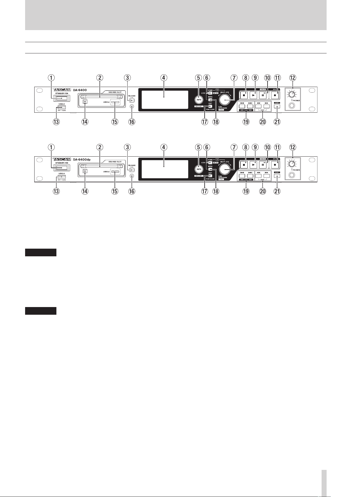
Front panel
8
DA-6400 front panel
8
DA-6400dp front panel
2 – Names and Functions of Parts
1 STANDBY/ON switch
Use to turn the unit on and to put it into standby.
Press and hold it when the power is on to open a pop-up
message confirming that you want to put the unit into
standby.
When the pop-up is open, press and hold the MULTI JOG
dial to put the unit into standby.
CAUTION
Before turning the unit on, lower the volumes of connected
equipment to their minimum levels. Failure to do so could
result in a sudden loud noise that could harm hearing, for
example.
2 SSD/HDD SLOT
Use this bay to insert and remove SSD/HDD cases. (See
“Loading and removing SSD/HDD cases” on page 17.)
CAUTION
Do not remove the SSD/HDD case from the unit when the
SSD/HDD is being accessed (during recording, playback,
when data is being written or at other times when the SSD/
HDD case indicator is blinking orange).
3 RELEASE switch
Slide the RELEASE switch toward > to unlock the loaded
SSD/HDD case so that it can be removed.
4 Color display
Shows a variety of information.
5 INFO button and indicator
The INFO indicator lights blue when the unit is functioning
properly.
The INFO indicator lights red when an error or warning has
occurred with the unit.
Press this button when the INFO indicator is lit blue to show
the unit's operation status on the display. Press this button
when the INFO indicator is lit red to show the message on
the display. (See “INFO button and indicator appearance” on
page 51.)
Press this button while pressing and holding the SHIFT
button to open the
marks” on page 45.)
MARK INFO
screen. (See “Using
6 HOME [METER] button
o Press when the Home Screen is open to change the time
display mode.
o When a Menu Screen is open, press this button to return
to the Home Screen.
o While pressing and holding this button, turn the MULTI
JOG dial to adjust the brightness of the color display and
the various indicators. (See “Adjusting the brightness” on
page 19.)
o While pressing and holding this button, press and turn the
MULTI JOG dial to adjust the brightness of just the color
display. (See “Adjusting the brightness” on page 19.)
o When the meter mode setting is 32ch, press this button
while pressing and holding the SHIFT button to switch
between showing level meters for channels 1-32 and
33-64 on the Home Screen. (See “Setting the meter mode”
on page 53.)
7 MULTI JOG dial
This dial functions both as a dial when turned and as a
button when pressed.
Dial functions
o When the white solo selection frame is shown on the
Home Screen, turn the MULTI JOG dial to move the solo
selection frame for headphone output left and right to
select the channel(s) output from the PHONES jack.
o When the gray solo selection frame is shown on the Home
Screen, turn the MULTI JOG dial to move between marks
in the current take. When there are no marks, turn to skip
between takes.
o When a Menu Screen is open, turn to select items and
change setting values.
o When editing names, use to select characters.
o While pressing and holding the HOME [METER] button,
turn the MULTI JOG dial to adjust the brightness of the
color display and the various indicators.
o While pressing and holding the HOME [METER] button,
press and turn this dial to adjust the brightness of just the
color display.
TASCAM DA-6400/DA-6400dp
9

2 – Names and Functions of Parts
o When the
folders. (See “Navigating the BROWSE screen” on page
30.)
Button functions
o When the Home Screen is open and the unit is stopped,
recording, in recording standby, playing back or in
playback standby, press this button to add a mark. (See
“Mark functions” on page 45.)
o When the Home Screen is open, press the MULTI JOG dial
while pressing and holding the SHIFT button to switch
the solo selection frame color.
o When the Home Screen is open, press and hold the MULTI
JOG dial while pressing and holding the SHIFT button to
switch the headphone monitoring mode between STEREO
and MONO. (See “Setting headphones monitoring mode”
on page 20.)
o When a Menu Screen is open, press to confirm selections
and settings (
o When the
the pop-up folder/file menu for the selected folder/file.
(See “Folder operations” on page 30.) (See “Take and file
operations” on page 31.)
o When the
turn the MULTI JOG dial while pressing and holding the
SHIFT button to make rough setting changes (MOVE Fast
operation).
8 8 button
Press to stop playback or recording.
BROWSE
ENTER
BROWSE
BROWSE
screen is open, turn this to select
button function).
screen is open, press this to show
screen or a Menu Screen is open,
e USB2.0 port
Connect (and disconnect) USB flash drives here. (See
“Connecting and disconnecting USB flash drives” on page
18.)
When a USB flash drive is connected, files can be copied
between it and the SSD/HDD drive. In addition, you can
also connect a USB keyboard here, and use it to input
characters for folder and file names, for example as well
as for external control. By default, the unit is set to use a
Japanese keyboard. Since English and Japanese keyboards
use different layouts, you should change the setting on
the
KEYBOARD TYPE
keyboard. (See “Setting the keyboard type” on page 53.)
r SSD/HDD slot power/access indicator
This lights blue when powered and the SSD/HDD is not
being accessed.
The SSD/HDD slot indicator blinks orange when the drive is
being accessed.
t SSD/HDD slot USB 3.0 port
Use the included USB cable to connect the unit to a
computer.
Use this port when exchanging data between a computer
and the SSD/HDD drive.
When connected to a USB 2.0 port, only USB 2.0 transfer
speeds are supported.
y Security screw hole
You can use the included security screw kit to lock the
RELEASE switch. (See “Using the security screw” on page
17.)
screen if you are using an English
9 7 button and indicator
Press when stopped or playback ready to start playback.
Press when in recording standby to start recording.
This button lights during playback and recording.
0 9 [CHASE] button and indicator
Press when stopped or playing back to start playback
standby.
Press when recording to start recording standby.
This button lights when in playback or recording standby.
q 0 [SPLIT] button and indicator
Press when stopped to start recording standby.
This button lights when recording or in recording standby.
Press when recording to stop recording to the current take
and start recording to a new take without pausing.
w PHONES jack and knob
Use this standard stereo jack to connect stereo headphones.
Use an adapter to connect headphones with a mini plug.
Use the PHONES knob to adjust the headphone output
level.
CAUTION
Before connecting headphones, minimize the volume with
the PHONES knob. Failure to do so might cause sudden loud
noises, which could harm your hearing or result in other
trouble.
u EXIT [PEAK CLEAR] button
When a setting screen is open, press this button to go back
one step in the menu.
Press this button to answer “NO” to a confirmation pop-up
message.
When the Home Screen is open, press this button to clear
level meter peak holds.
i MENU button
When the Home Screen is open, press this button to open
the Menu Screen. (See “Menu structure” on page 14.) and
(See “Basic Menu Screen operations” on page 16.).
o .// [MARK .//] buttons
Press these buttons to skip to the previous/next take.
Press these buttons while pressing and holding the SHIFT
button to move to the previous/next mark.
p m/, buttons
Press and hold these buttons to search backward/forward.
When searching one way, press and hold the button for the
opposite direction (m or ,) to search at high speed.
TASCAM DA-6400/DA-6400dp
10
2 – Names and Functions of Parts
a SHIFT button
o When the Home Screen is open, press the MULTI JOG
dial while pressing and holding this button to show a
white frame in the meter section, and turn the MULTI JOG
dial to select the audio channel to be output from the
PHONES jack.
o When the Home Screen is open, press and hold the MULTI
JOG dial while pressing and holding the SHIFT button to
switch the headphone monitoring mode between STEREO
and MONO. (See “Setting headphones monitoring mode”
on page 20.)
o When the meter mode setting is 32ch, press the HOME
[METER] button while pressing and holding this button
to switch between showing level meters for channels 1-32
and 33-64 on the Home Screen. (See “Setting the meter
mode” on page 53.)
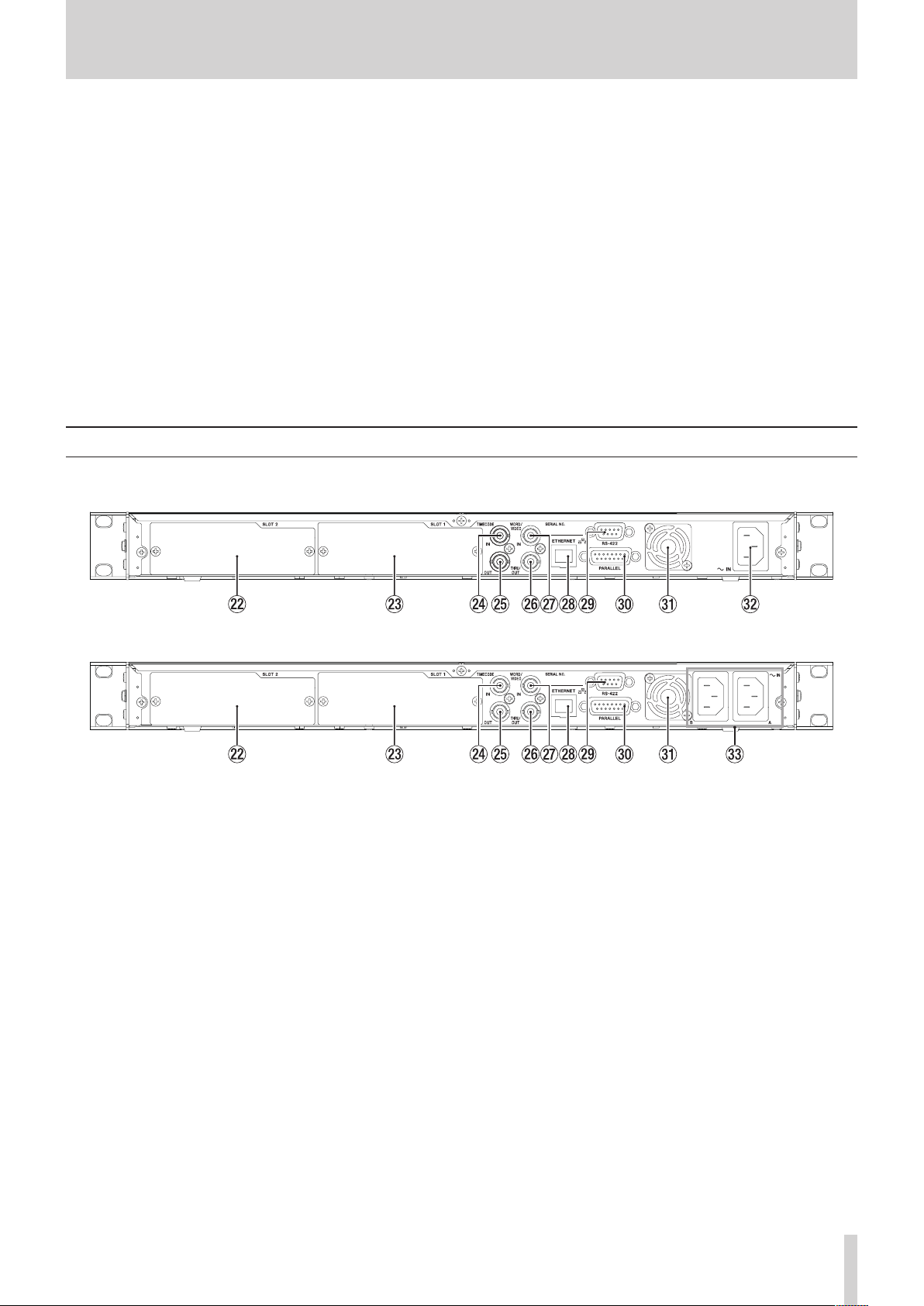
Rear panel
8
DA-6400 rear panel
o Press the INFO button while pressing and holding this
button to open the
o Press the MENU button while pressing and holding this
button to open the menu pages in the opposite direction.
o When an audio output channel is selected on the Home
Screen, when a channel is selected for setting changes on
the
REC FUNCTION
when a folder is selected on the
MULTI JOG dial while pressing and holding this button to
move the cursor by large amounts.
When stopped, in playback standby or playing back.
o Press this button while pressing and holding the .
[MARK .] button to move to the previous mark and
resume the previous state.
o Press this button while pressing and holding the /
[MARK /] button to move to the next mark and
resume the previous state.
MARK INFO
or
INPUT MONITOR
BROWSE
page.
screen, or
screen, turn the
8
DA-6400dp rear panel
s SLOT 2
Use this slot to install an I/O card (sold separately).
d SLOT 1
Use this slot to install an I/O card (sold separately).
f TIMECODE IN connector
This BNC connector is for the input of SMPTE timecode.
g TIMECODE OUT connector
This BNC connector is for the output of SMPTE timecode.
h WORD/VIDEO THRU/OUT connector
This BNC connector is for the output of word clock and video
reference signals.
This connector outputs word clock signals (thru or 44.1, 48,
88.2 or 96 kHz) and video reference signals (signal thru from
IN jack).
j WORD/VIDEO IN connector
This BNC connector is for the input of word clock and video
reference signals. Use this connector to input word clock
signals (44.1, 48, 88.2 or 96 kHz) and video reference signals
(NTSC/PAL blackburst and HDTV tri-level).
k ETHERNET connector
This is an Ethernet port. Use this to connect to a network,
transfer files and control the unit externally.
l RS-422 terminal
This is a 9-pin D-sub RS-422 serial control terminal.
Connect an external controller here.
; PARALLEL connector
This is a 15-pin D-sub parallel control terminal.
Connect an external controller here.
z Heat dissipation fan
This fan is to prevent the unit from overheating. Do not
allow anything to block the fan and prevent the dispersion
of heat.
x AC IN connector (DA-6400 only)
Plug the included power cord in here.
c AC IN A/B connectors (DA-6400dp only)
Plug the included power cords in here.
To operate the unit with power supply redundancy, connect
power supplies to both the AC IN A and AC IN B connectors.
TASCAM DA-6400/DA-6400dp
11
2 – Names and Functions of Parts
START
Note about the PARALLEL connector
The PARALLEL connector on the back of the unit allows
external control of it.
You can set the functions of the PARALLEL connector on the
PARALLEL INPUT
“PARALLEL connector settings” on page 38.)
The factory default pin assignments are as follows.
Pin No. I/O Function (default value)
1 O OUTPUT AUX1 (STOP TALLY)
2 O OUTPUT AUX2 (REC TALLY)
3 I INPUT AUX1 (TAKE SKIP +)
4 I INPUT AUX2 (TAKE SKIP −)
5 O OUTPUT AUX3 (ERROR TALLY)
6 I INPUT AUX3 (FADER REC)
7 I INPUT AUX4 (REW)
8 GND
9 O OUTPUT AUX4 (PLAY TALLY)
10 O OUTPUT AUX5 (PAUSE TALLY)
11 I INPUT AUX5 (F.FWD)
12 I STOP
13 I PLAY
14 I INPUT AUX6 (PAUSE)
15 +5V
I: For command input and transport control
Internal circuit with +5V pull-up
Operates with low signal input of 50 msec or longer
When INPUT AUX is set to FADER REC, low signal input
starts recording and high signal input stops recording.
When INPUT AUX is set to FADER START, low signal input
starts playback and high signal input pauses playback.
O: For command and tally output
Internal circuit is open collector (10Ω output impedance)
Outputs low command during operation
20V dielectric strength, 35mA maximum current
+5V: 50mA maximum supplied current
The following example is of a connection that controls recording
and playback of this unit by level, using fader starts and stops
and FADER REC commands.
NOTE
Setting multiple FADER REC and FADER START settings to
INPUT AUX is not possible.
STOP
STOP
and
PARALLEL OUTPUT
Pin 8 : GND
Pin 6 : REC
pages. (See
PARALLEL
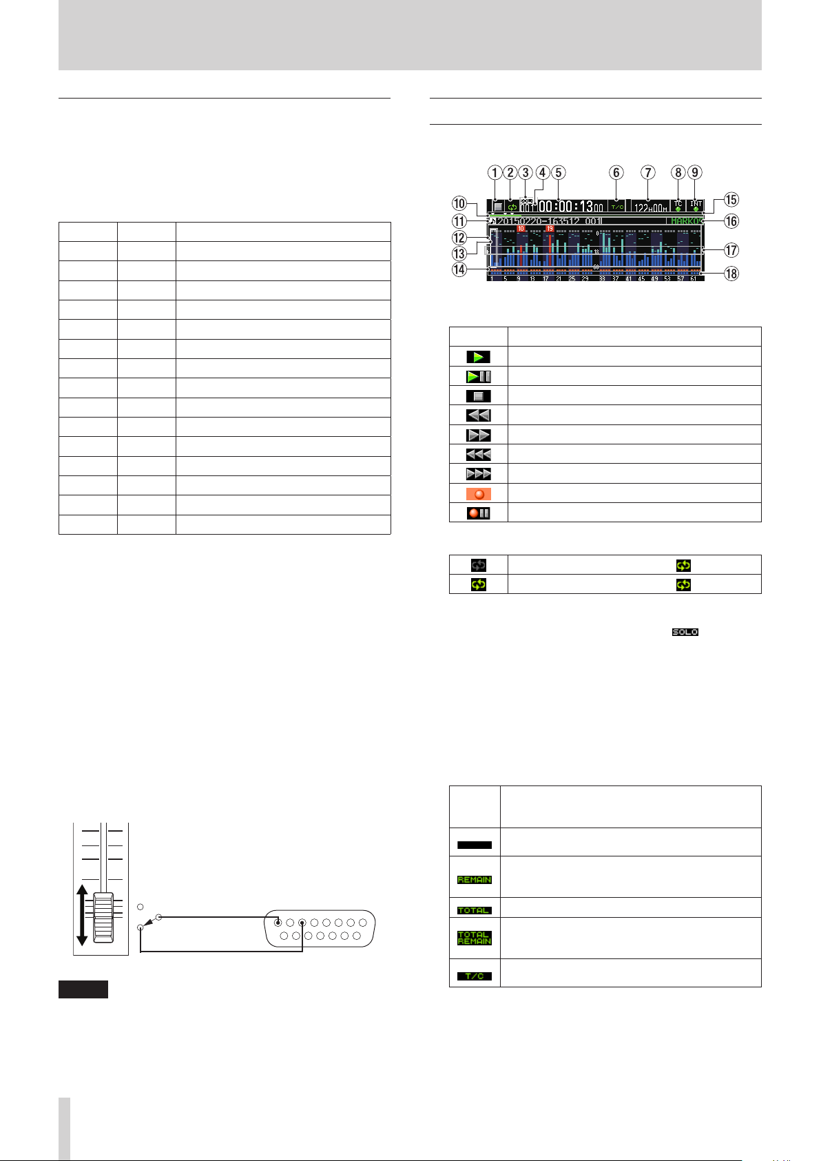
Home Screen
The following information is shown on the unit's display.
1 Transport status
This icon shows the current transport status.
Icon Meaning
Playing back
In playback standby
Stopped
Searching backward
Searching forward
Searching backward (high speed)
Searching forward (high speed)
Recording
In record standby
2 Repeat status
When repeat playback is off, the icon is unlit.
When repeat playback is on, the icon is lit.
3 Solo status
When the solo selection frame is white, the icon blinks.
4 Take number
This shows the number of the take playing or being
recorded.
5 Time counter
This shows the elapsed recording/playback time of the take
or the timecode time.
6 Time display mode
This icon shows the current time display mode.
Time
display
mode
Meaning
This shows the elapsed time from the beginning
of the take.
This shows the remaining time until the end of
take. When recording, this shows the remaining
time until the maximum file size is reached.
This shows the total take elapsed time.
During playback, this shows the total take
remaining time. When recording, this shows the
remaining available recording time.
This shows the timecode time of the recording/
playback take.
12
TASCAM DA-6400/DA-6400dp

2 – Names and Functions of Parts
7 Remaining media capacity
This shows the remaining available recording time of the
current media.
No Media
UNFORMAT
been formatted.
Rec Limit
the total number of folders, takes inside folders and other
files would exceed the system limit.
8 Timecode status
When the
TC SYNC REC
When the
SYNC REC
9 Audio synchronization status
The name of the currently selected master clock is shown
with the indicator. (See “Setting the master clock” on page
22.)
0 Time bar
This shows the current playback position. What is shown
depends on the time display mode.
Time
display
mode
is shown when no SSD/HDD drive is loaded.
is shown if the loaded SSD/HDD drive has not
is shown if recording is not possible because
TC GENERATOR MODE
.
The TC indicator lights green when correct
timecode is being input and recognized
properly.
The indicator does not light when input
timecode recognition is abnormal.
TC GENERATOR MODE
.
The TC indicator lights red when correct
timecode is being input and recognized
properly.
§
§
The indicator flashes red when input
timecode recognition is abnormal.
When synchronized with the master clock,
the indicator lights green.
When not synchronized with the master
clock, the indicator blinks.
Meaning Bar display
The current playback
position is shown relative
to the length of the take.
The current playback
position is shown relative
to the length of all takes
in the folder.
(Vertical white lines show
divisions between takes.)
The current playback
position is shown relative
to the length of the take.
screen is not set to
screen is set to
Lengthens from the
left end toward the
right end.
Shortens from the left
end toward the right
end.
Lengthens from the
left end toward the
right end.
Shortens from the left
end toward the right
end.
Lengthens from the
left end toward the
right end.
TC
When a level overloads, the bar meter becomes red and the
channel number appears in a pop-up above it.
e Solo selection frame
The level meter for the channel currently output from the
PHONES jack is shown with a white or gray frame. When the
selection frame appears white, turn the MULTI JOG dial to
select the channel output from the PHONES jack.
Press the MULTI JOG dial while pressing and holding
the SHIFT button to switch the headphone output solo
selection frame to white/gray.
When the
MONO, the solo selection frame will be for a mono channel.
(See “Setting headphones monitoring mode” on page 20.)
r Record function indicators
These show whether recording is enabled or not for each
channel.
t Marks
An b icon is shown at each mark.
y Mark name
This shows the name of the mark at or immediately before
the current time.
u Level meter guide
This level meter guide can be used to evaluate input and
output levels.
This line is shown at −18 dB.
The position of the guide and the value (t 18 g) shown
depend on the value set on the
screen. (See “Setting the reference level” on page 23.)
i Input monitoring indicator area
These show whether input monitoring is enabled or not for
each channel.
Input monitoring on: Blue
Input monitoring off: Unlit
PHONES MONITOR MODE
Recording enabled: Red
Recording disabled: Gray
screen setting is
REFERENCE LEVEL
NOTE
When the sampling frequency is 88.2/96 kHz, the following
data in the area for channels 33–64 is not shown.
i Level meters
i Record function indicators
i Input monitoring indicators
Furthermore, the solo selection frame cannot be moved to
channels 33–64.
NOTE
During recording, a progress bar appears to extend from the
left end to the right end about every 10 seconds.
q Take name
This shows the name of the currently loaded take.
w Level meter display area
This area shows the levels of the input and playback signals.
TASCAM DA-6400/DA-6400dp
13
2 – Names and Functions of Parts
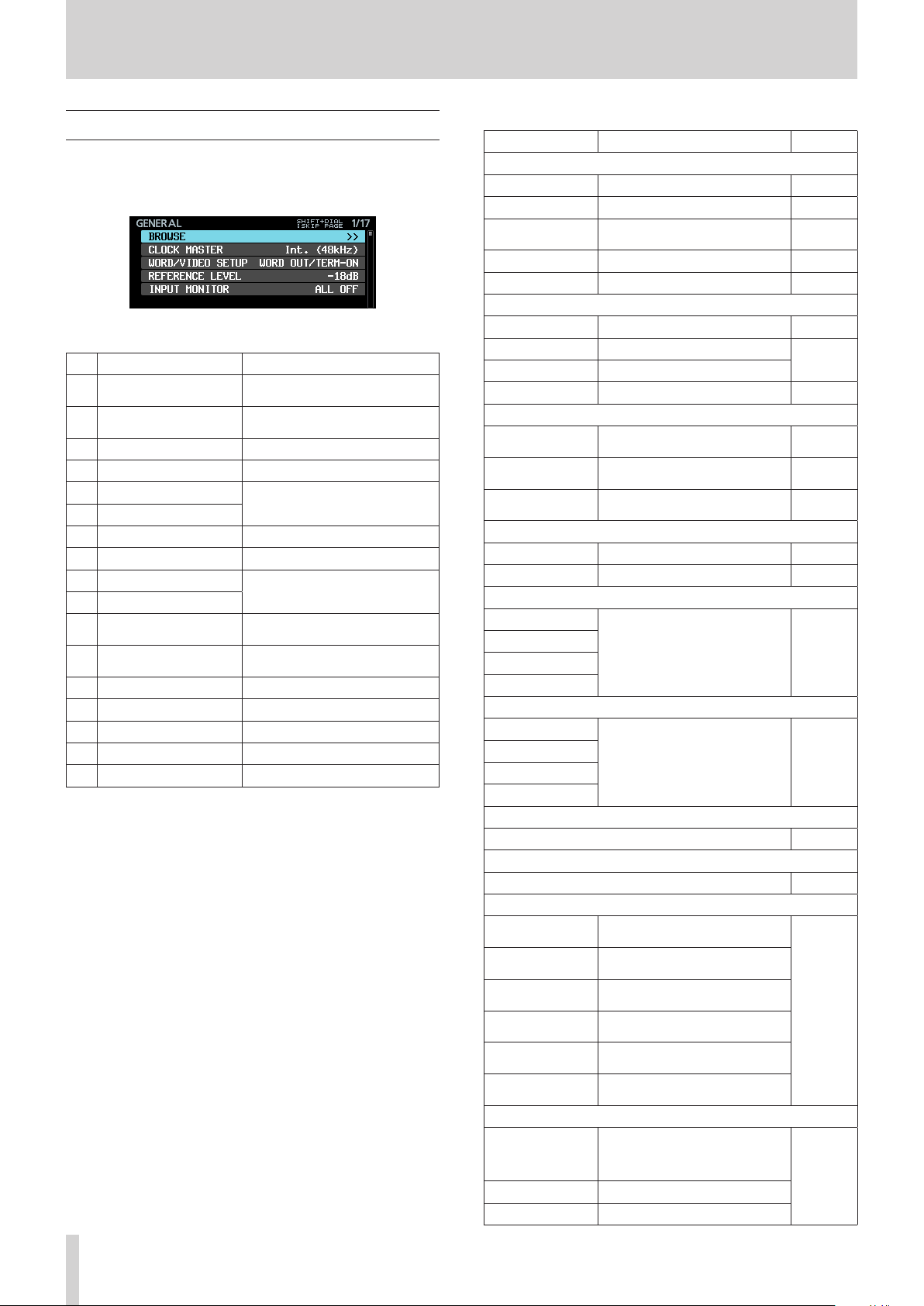
Menu structure
Press the MENU button to open the
menu the first time. In the future, pressing this button will
reopen the menu page that was last open.
The MENU screen has 17 pages organized by types of menu
items.
Page name Contents
1 GENERAL
2 REC FILE FORMAT
3 REC OPTIONS Make recording option settings.
4 PLAY SETUP Make playback settings.
5 INPUT ROUTING 1
6 INPUT ROUTING 2
7 SLOT 1 Make settings for SLOT 1.
8 SLOT 2 Make settings for SLOT 2.
9 TC SETUP 1
10 TC SETUP 2
11 PARALLEL INPUT
12 PARALLEL OUTPUT
13 NETWORK Make network settings.
14 SNTP Make SNTP settings.
15 MEDIA Work with media.
16 PREFERENCES Make preference settings.
17 SYSTEM SETUP Make system settings.
GENERAL
Make settings for general
functions.
Make recording file format
settings.
Make input routing settings.
Make settings related to
timecode.
Make input settings for the
PARALLEL connector.
Make output settings for the
PARALLEL connector.
page of the
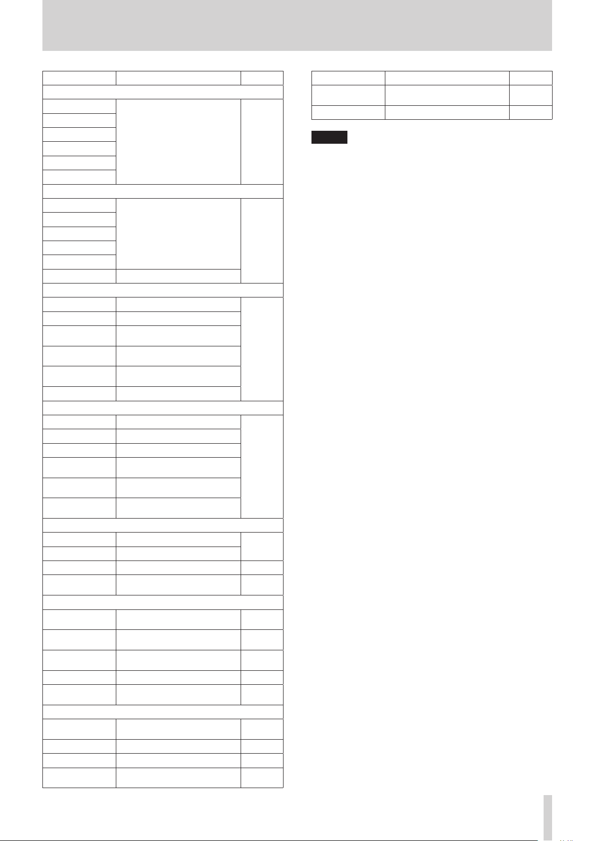
The various menu items are as follows.
Menu item Function Page
GENERAL page
BROWSE Open BROWSE screen page 30
CLOCK MASTER Set the master clock page 22
WORD/VIDEO
SETUP
REFERENCE LEVEL Set the reference level page 23
INPUT MONITOR Set input monitoring function page 23
REC FILE FORMAT page
REC FUNCTION Make recording channel settings page 24
BIT LENGTH Set the bit length
REC Fs Set the sampling frequency
FILE NAME Set the file name format page 26
REC OPTIONS page
AUTO FILE
INCREMENT
AUTO MARK
PAUSE MODE
PLAY SETUP page
PLAY MODE Set the playback mode page 35
REPEAT MODE Set the repeat mode page 35
INPUT ROUTING 1 page
CHANNEL 1-8
CHANNEL 9-16
CHANNEL 17-24
CHANNEL 25-32
INPUT ROUTING 2 page
CHANNEL 33-40
CHANNEL 41-48
CHANNEL 49-56
CHANNEL 57-64
SLOT 1 page
Set various functions for the card loaded in SLOT 1 page 28
SLOT 2 page
Set various functions for the card loaded in SLOT 2 page 28
TC SETUP 1 page
GENERATOR TC
GENERATOR U.B.
TC INPUT
MONITOR
TC INPUT FRAME
TC INPUT U.B.
START TIME
TC SETUP 2 page
Make word/video connector
settings
Make automatic take function
settings
Make automatic mark function
settings
Make pause mode function
settings
Make input routing settings page 28
Make input routing settings page 28
Set the timecode for the
timecode generator
Set the user bits (U.B.) for the
timecode generator
View the input timecode time
View the input timecode frame
type
View the user bits (U.B.) for the
input timecode
Set the time when timecode
resumes
page 23
page 25
page 27
page 27
page 28
page 36
TASCAM DA-6400/DA-6400dp
14
TC GENERATOR
MODE
TC FRAME TYPE Set the timecode frame type
TC OUTPUT MODE Set the timecode output mode
Set the mode for the timecode
generator
page 37
2 – Names and Functions of Parts
Menu item Function Page
PARALLEL INPUT page
INPUT AUX1
INPUT AUX2
INPUT AUX3
INPUT AUX4
INPUT AUX5
INPUT AUX6
PARALLEL OUTPUT page
OUTPUT AUX1
OUTPUT AUX2
OUTPUT AUX3
OUTPUT AUX4
OUTPUT AUX5
EOM Set the EOM function
NETWORK page
MAC ADDRESS View the unit's MAC address
IP ADDRESS View the current IP address
DNS ADDRESS
IP SETUP
DNS SETUP
PASSWORD Set the password
SNTP page
SNTP STATUS View the SNTP function status
SNTP UPDATE Set the SNTP update mode
NTP SERVER Set the NTP server name
UPDATE TIME
TIME ZONE
DST SETUP
MEDIA page
QUICK FORMAT Quickly format media
FULL FORMAT Format media completely
MEDIA INFO Show media information page 52
SSD/HDD
USB CONNECT
PREFERENCES page
PHONES MONITOR
MODE
PEAK HOLD TIME
METER MODE
KEYBOARD TYPE Set the keyboard type page 53
POWER REDUN-
DANCY CHECK
SYSTEM SETUP page
SYSTEM BACKUP
FACTORY PRESET Restore factory default settings page 56
OSCILLATOR Make oscillator settings page 44
CLOCK ADJST
Set the input function for the
PARALLEL connector
Set the output function for the
PARALLEL connector
View the IP address of the DNS
server
Set the unit's IP address and
related settings
Set the IP address of the DNS
server
Set the time to the time
acquired from the NTP server
Set the time offset from Coordinated Universal Time (UTC)
Set the daylight savings time
function
Connecting an SSD/HDD to a
computer
Set headphones monitoring
mode
Set the level meter peak hold
time
Set the number of level meter
channels shown
Set the power supply redundancy check function
Export/import system backup
data
Set the built-in clock date and
time
page 38
page 38
page 39
page 40
page 19
page 49
page 20
page 53
page 53
page 55
page 55
page 19
Menu item Function Page
VERSION INFO
F/W UPDATE Update the firmware page 52
Show system version information
page 51
NOTE
The settings for all menu items, except the oscillator on/off
setting, are retained even when the unit is turned off.
TASCAM DA-6400/DA-6400dp
15
2 – Names and Functions of Parts
GENERAL
REC FILE FORMA
REC OPTION
PLA
INPUT ROUTING1
INPUT ROUTING2
SL
SL
T
T
C SETUP 2
T
Basic Menu Screen operations
Use the following operations to work with the pages of the
Menu Screen.
8
Changing menu items by page:
Press the MENU button repeatedly until the desired menu page
opens.
The pages will open in the following order.
SYSTEM SETUP
T
PREFERENCES
S
Y SETUP
OT 1
OT 2
C SETUP 1
MEDIA
SNTP
NETWORK
PARALLEL OUTPU
PARALLEL INPUT
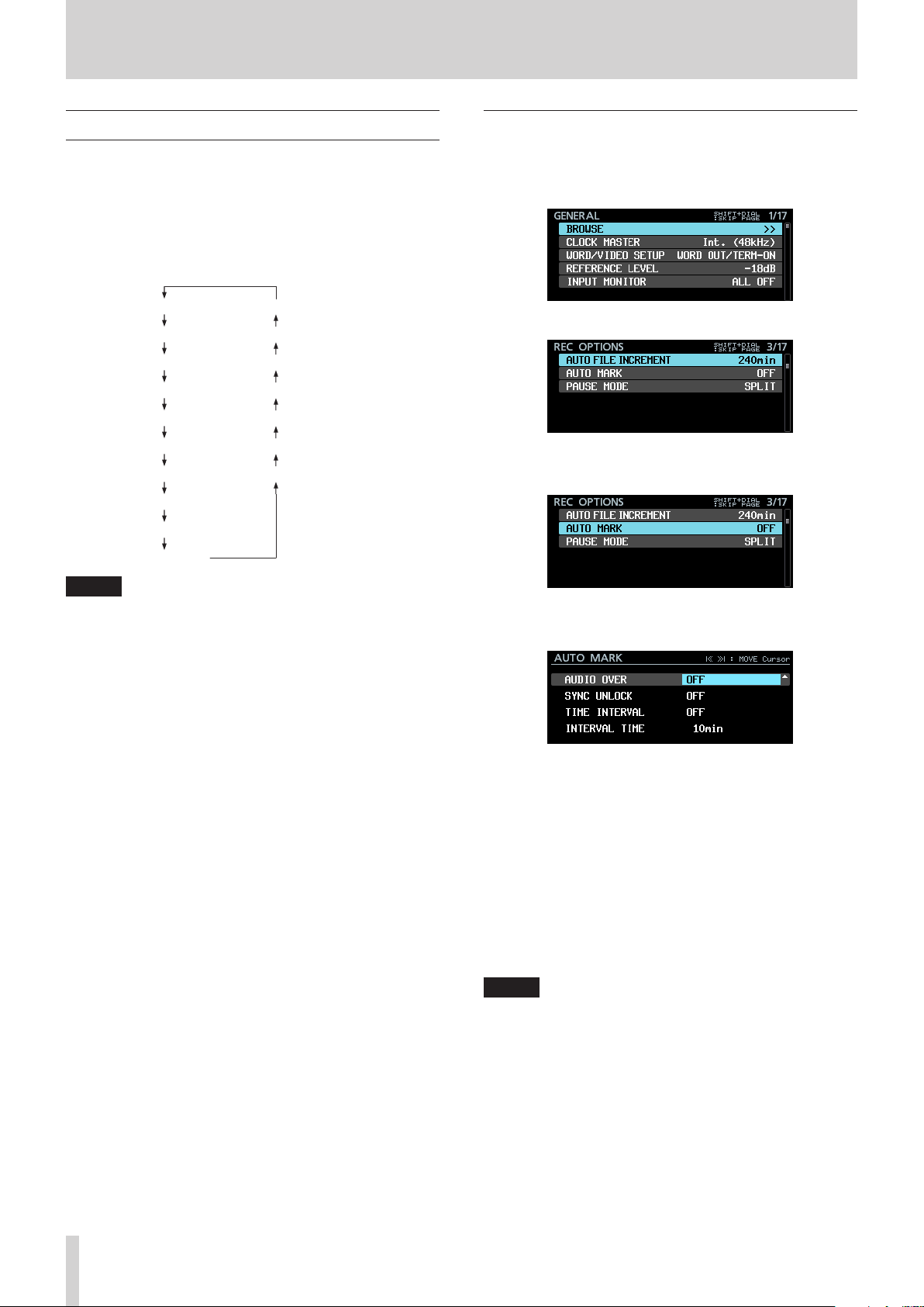
Menu operation procedures
In this example, we explain how to set the auto mark function.
1. Press the MENU button and open the
page.
2. Press the MENU button to open any other menu page.
REC OPTIONS
3. Turn the MULTI JOG dial to select the item to set.
GENERAL
page open
menu
NOTE
•
Press the MENU button while pressing and holding the
SHIFT button to open menu pages in the opposite direction.
•
Turn the MULTI JOG dial to move up or down one item at
a time from the
SYSTEM SETUP
•
Turn the MULTI JOG dial while pressing and holding the
SHIFT button to move up or down one menu page at a time.
8
Selecting items (moving vertically on a page):
Turn the MULTI JOG dial.
8
Confirming a selected item:
Press the MULTI JOG dial.
8
Opening a submenu from a page:
Press the MULTI JOG dial.
8
Going back one step in a menu:
Press the EXIT [PEAK CLEAR] button.
8
Returning directly to the Home Screen from a menu:
Press the HOME [METER] button.
GENERAL
page
F/W UPDATE
page
BROWSE
item.
item to the
AUTO MARK
selected
4. Press the MULTI JOG dial to open the settings screen.
AUTO MARK
screen open
5. Turn the MULTI JOG dial to change the setting.
6. To set another item on the same screen, press the MULTI
JOG dial to move the cursor to the next setting.
When
|<< >>| : MOVE Cursor
appears at the
top right of the screen, you can use the .// [MARK
.//] buttons to move the cursor.
7. Repeat steps 5 to 6 as necessary to set other items.
8. On the last item, press the MULTI JOG dial to confirm the
changed settings and return to the Menu Screen.
Press the HOME [METER] button to return to the Home
Screen.
NOTE
•
Press the EXIT [PEAK CLEAR] button to cancel the menu
operation and return to the Menu Screen.
•
Menu items that cannot be changed are shown with gray
characters and cannot be selected using the MULTI JOG
dial.
TASCAM DA-6400/DA-6400dp
16
3 – Preparation
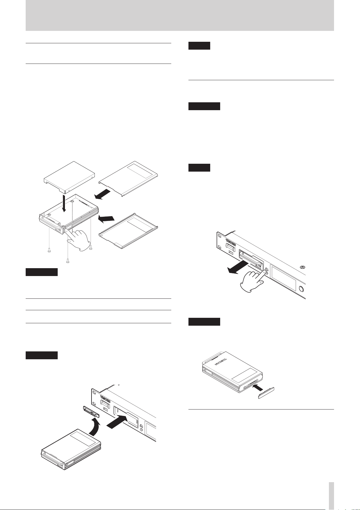
Installing an SSD/HDD drive in the case
1. While pressing the cover lock on the left side of the
SSD/HDD case handle, slide the lower cover toward the
connector and remove it.
2. While pressing the cover lock on the right side of the
SSD/HDD case handle, slide the upper cover toward the
connector and remove it.
3. Place the SSD/HDD drive in the top of the case, and attach it
to the connector at the handle end.
4. Attach the set SSD/HDD drive with screws through the
bottom of the case.
5. While pressing the cover lock part of the SSD/HDD case,
slide the lower and upper covers from the connector end to
attach them.
NOTE
•
If you are unable to insert the SSD/HDD case properly, try
removing it once and reinserting it.
•
You can insert a case even when the unit is on.
Removing an SSD/HDD case
SSD/HDD cases can be ejected.
CAUTION
Do not remove the SSD/HDD case from the unit when the
SSD/HDD is being accessed (during recording, playback,
when data is being written or at other times when the
SSD/HDD case indicator is blinking orange). Removing a
case when its drive is being accessed could cause proper
recording to fail, recorded data to be lost, and sudden loud
noises from monitoring equipment, which might damage
the equipment or harm hearing.
NOTE
You can remove the SSD/HDD case from the unit even when
the unit is on as long as the SSD/HDD is not being accessed
(during recording, playback, when data is being written or
at other times when the SSD/HDD case indicator is blinking
orange).
1. Slide the RELEASE switch toward >.
This unlocks the loaded SSD/HDD case so that it can be
removed.
CAUTION
Be careful not to squeeze parts near the handle when
attaching the upper and lower covers.
Loading and removing SSD/HDD cases
Loading an SSD/HDD case
Insert the SSD/HDD case into the SSD/HDD SLOT on the front of
the unit until they are even.
CAUTION
Before inserting the SSD/HDD case into the main unit,
remove the static electricity protection cover from the SSD/
HDD case main unit connector.
Static electricity
protection cover
2. While sliding the RELEASE switch toward >, grasp the
SDD/HDD case by hand and pull it out.
CAUTION
After removing the SSD/HDD case from the main unit,
attach the static electricity protection cover to the SSD/HDD
case main unit connector.
Static electricity
protection cover
Using the security screw
You can use the included security screw kit to lock the SDD/HDD
case so that cannot be removed.
Use a Phillips (+) driver to install/remove the security screw.
TASCAM DA-6400/DA-6400dp
17

3 – Preparation
NOTE
During installation, be careful not to tighten the screw too
much.
Connecting and disconnecting USB flash drives
You can connect and disconnect USB flash drives whether the
unit is on or off.
CAUTION
Do not disconnect a USB flash drive when it is being
accessed in one of the following manners.
Doing so could damage data or the USB flash drive.
Moreover, disconnecting the USB flash drive during the
execution of a firmware update could result in the unit
becoming unable to start up or operate properly.
i During execution of the
i During execution of a
EXPORT
i During execution of a firmware update
i When the
drive is being accessed
BROWSE
Installing I/O cards (sold separately)
CAUTION
Before installing or removing an I/O card (sold separately),
disconnect the power cord from the outlet or the unit.
FACTORY PRESET
SYSTEM BACKUP
screen is open and the USB flash
function
IMPORT or
securely. Push the I/O card in until its backplate reaches the
back panel of the unit, leaving no gap, and clicks into place.
Do not force the card into the slot. If you cannot insert the
card properly, remove it once and try reinserting it.
3. Use the two removed screws to secure the I/O card in place.
4. Turn the unit on, and check the
MATION
inserted I/O card. (See “Checking the firmware version” on
page 51.)
If “SLOT1 : ---- (None)” or something similar appears, the card
might not be inserted correctly or the screws might not be
tightened securely. Insert the I/O card securely into the unit
again.
screen to confirm that it has recognized the
VERSION INFOR-
Turning the unit on and off (putting it in standby)
When the unit is off, press the STANDBY/ON switch on the front
of the unit to turn it on.
DA-6400dp startup screen
Home Screen
After the unit starts and the startup screen is shown, the Home
Screen will open.
If no SSD/HDD is loaded in the slot or there are no audio files in
the current folder, the take number and time will not be shown
on the Home Screen.
8
Turning the unit off:
Press and hold the STANDBY/ON switch to open a pop-up
message.
When the confirmation pop-up is open, press and hold the
MULTI JOG dial to turn the unit off.
1. Remove the two screws from the plain panel and remove
the panel itself. (If a different card is already installed,
remove it.)
2. Insert the I/O card into the card slot. Align the edges of the
I/O card with the white guides inside the slot and insert it
TASCAM DA-6400/DA-6400dp
18
CAUTION
•
Do not turn the unit off (put it into standby) during
recording, playback or at other times when data on the
SSD/HDD is being accessed. The SSD/HDD case indicator
blinks orange at such times. Doing so could cause proper
recording to fail, recorded data to be lost, and sudden loud
noises from monitoring equipment, which might damage
the equipment or harm hearing.
•
When the unit is started up for the first time (or when the
built-in clock is reset after being left unused without power
for a long time), the
after the start-up screen to allow the date and time of the
built-in clock to be set. (See “Setting the built-in clock date
and time” on page 19.)
CLOCK ADJUST
screen appears
3 – Preparation
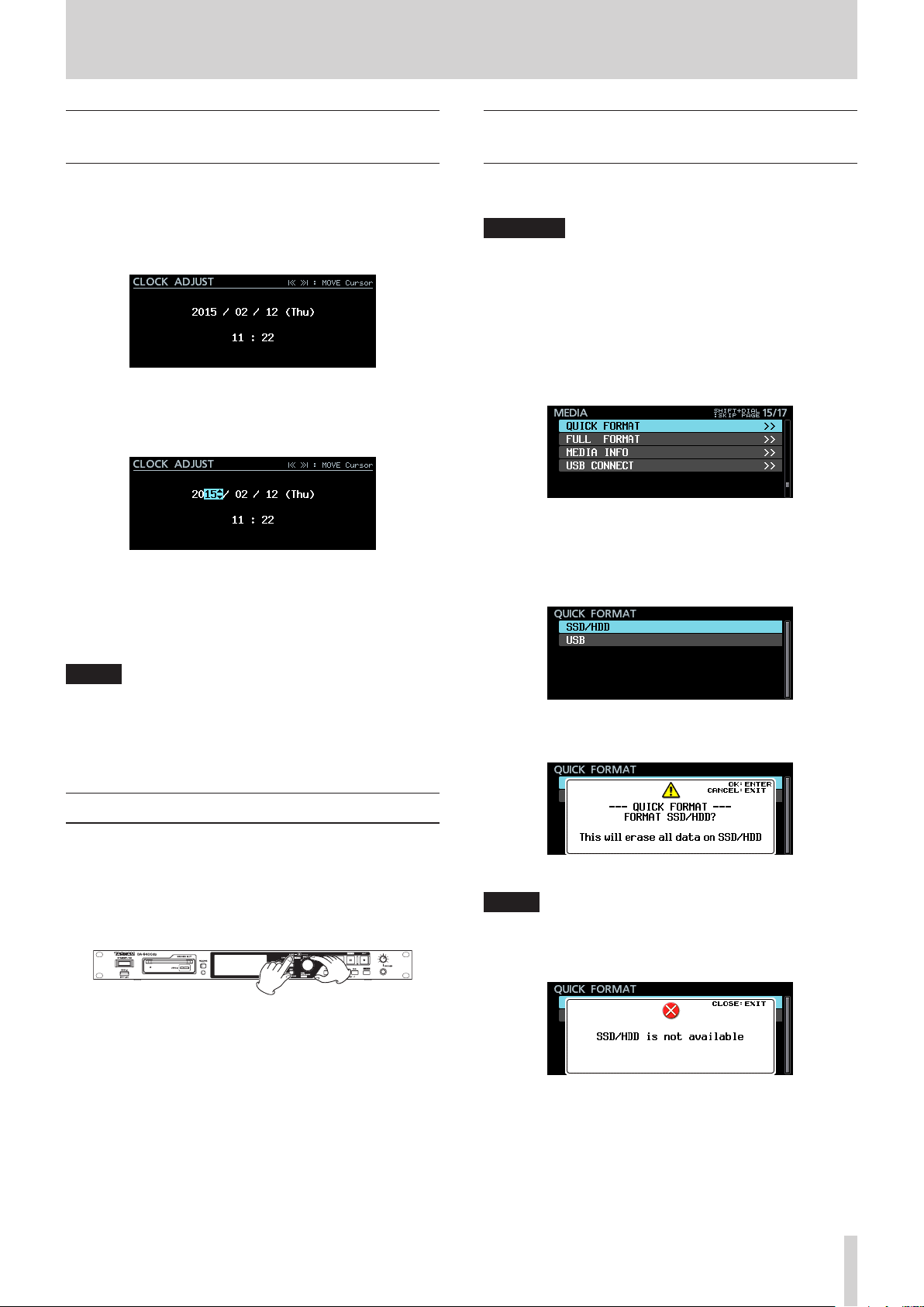
Setting the built-in clock date and time
Using its internal clock, this unit includes the date and time
when a file is recorded.
1. Select the
SETUP
“Menu operation procedures” on page 16.)
2. Press the MULTI JOG dial to enter setting mode and show
the cursor on the item to be changed.
Use the .// [MARK .//] buttons to move the
cursor.
3. Turn the MULTI JOG dial to change a value, and press the
MULTI JOG dial to confirm it and move the cursor to the
next item.
4. The cursor will disappear and setting the time of the built-in
clock will complete after you change the year, month, day,
hour and minute in order.
CLOCK ADJUST
page to open the
item on the
CLOCK ADJUST
SYSTEM
screen. (See
Preparing SSD/HDD drives and USB flash drives for use
In order to use an SSD/HDD drive or USB flash drive with this
unit, you must use this unit to format it first.
CAUTION
•
Formatting erases all the data on the SSD/HDD drive or USB
flash drive. Confirm that this is okay before proceeding.
•
Always use this unit to format medias to be used with it.
Operation of this unit might be affected when using an
SSD/HDD or USB flash drive that has been formatted by a
computer or other device.
1. On the
2. When the
MEDIA
FULL FORMAT
on page 16.)
QUICK FORMAT
data.
FULL FORMAT
opens, select the media to format.
page, select the
item. (See “Menu operation procedures”
: Format only media management
: Completely format the media.
QUICK FORMAT
or
QUICK FORMAT
FULL FORMAT
or
screen
NOTE
When making a setting, you can press the EXIT [PEAK
CLEAR] button to cancel the changes and return to the
Menu Screen.
5. Press the EXIT [PEAK CLEAR] button to return to the Menu
Screen.
Adjusting the brightness
While pressing and holding the HOME [METER] button, turn the
MULTI JOG dial to adjust the brightness of the color display and
the indicators.
While pressing and holding the HOME [METER] button, press
and turn the MULTI JOG dial to adjust the brightness of only the
color display.
When
QUICK FORMAT
The following pop-up message will appear.
When
QUICK FORMAT
selected
selected
NOTE
•
Press the EXIT [PEAK CLEAR] button to cancel formatting.
•
If no SSD/HDD drive is loaded, the following pop-up
message will appear.
TASCAM DA-6400/DA-6400dp
19
3 – Preparation
3. Press the MULTI JOG dial.
A second confirmation pop-up message will appear.
When
QUICK FORMAT
4. Press and hold the MULTI JOG dial to start formatting.
The following pop-up message will appear during
formatting.
When
QUICK FORMAT
5. When formatting ends, the pop-up disappears and the
Home Screen opens.
selected
selected
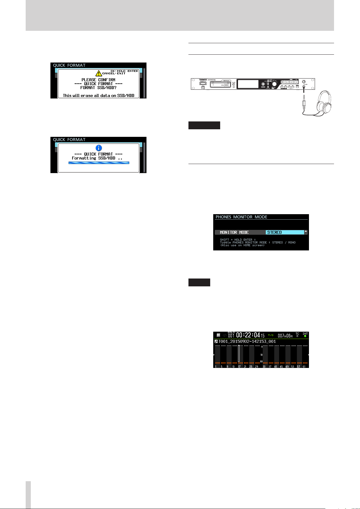
Connecting headphones
Connect headphones to the PHONES jack on the front of the
unit.
CAUTION
Before connecting headphones, minimize the volume with
the PHONES knob. Failure to do so might cause sudden loud
noises, which could harm your hearing or result in other
trouble.
Setting headphones monitoring mode
The headphones monitoring mode can be set.
1. Select the
PREFERENCES
MODE
16.)
PHONES MONITOR MODE
page to open the
screen. (See “Menu operation procedures” on page
item on the
PHONES MONITOR
2. Set the headphones monitoring mode.
Options:
3. Confirm the setting and return to the Menu Screen.
STEREO
(default),
MONO
NOTE
•
When making a setting, you can press the EXIT [PEAK
CLEAR] button to cancel the changes and return to the
Menu Screen.
•
When the headphones monitoring mode is set to MONO, the
solo selection frame on the Home Screen will be for a mono
channel.
•
When the Home Screen or
screen is open, press and hold the MULTI JOG dial while
pressing and holding the SHIFT button to switch the
headphone monitoring mode between STEREO and MONO.
PHONES MONITOR MODE
TASCAM DA-6400/DA-6400dp
20
 Loading...