

Page 1
© Tandberg Data ASA
September
2005
INSTALLATION
AND
ADMINISTRATION
MANUAL
TANDBERG DATA ASA
P.O. Box 134 Kjelsås
N-0411 OSLO, NORWAY
Phone + 47 22 18 90 90
Telefax + 47 22 18 95 50
Rev. 03
Page 2

mitted, transcribed, stored in
a retrieval system, or translated into any language or computer language, in any form or by any
mechanical, magnetic, optical, chemical, manual or otherwise, without the prior
pect to the contents hereof and
y particular purpose.
Furthermore, Tandberg Data reserves the right to revise this publication and to make changes from
All rights reserved. No part of this publication may be reproduced, trans
means, electronic,
written consent of Tandberg Data ASA.
This equipment has been tested and found to comply with the limits for a Class B digital device
pursuant to Part 15 of the FCC Rules and based on the standard of the Voluntary Control Council
for Interference by Information Technology Equipment (VCCI)
provide the reasonable protection against harmful interference in a residential installation. This
equipment
and used in accordance with the instructions, the radio frequency energy may cause harmful
interference to radio communications. However, there is no guarantee that in
occur in a particular installation. If this equipment does cause harmful interference to radio or
television reception, which can be determined by turning the equipment off and on, the user is
encouraged to try to correct the interfere
Disclaimer
Tandberg Data makes no representations or warranties with res
specifically disclaims any implied warranties of merchantability or fitness for an
generates, uses and can radiate radio frequency energy. If the device is not installed
Reorient or relocate the receiving antenna.
Increase the separation between the equipment and receiver.
Connect the equipment into an outlet on a circuit different from that to which the receiver is
connected.
Consult the dealer or an experienced radio/TV technician for help.
. These limits are designed to
terference will not
nce by one or more of the following measures.
time to time in the content hereof without oblig
Lithium Battery Notice
Do n
ot open battery, dispose of by burning, heat above 100° C (212° F), expose contents to water,
recharge, put in backwards, or use in combination with used batteries or other battery types.
Mishandling of a lithium battery may result in personal injury hazar
explosion.
ation to notify any person of such revisions or changes.
d do to leaked chemicals, fire, or
Page 3

Table of Contents
1.
Introduction................................................................................................
1.1
1.2
1.3
1.4 Backup 9
1.5
1.6
1.7
1.8
2
Before Connecting the BakStor...............................................................13
2.1
2.2
2.3
2.4
2.5
Important Safety Instr
Technical Specifications...................................................................
1.2.1
1.2.2
1.2.3
1.2.4
1.2.5
RAID
User-Friendly Configuration............................................................
Fault Tolerance.................................................................................
1.6.1
1.6.2
Additional Features and Options....................................................10
Notes on this manual......................................................................10
Unpacking.......................................................................................13
Connectors on the BakStor 1000 (1U-Unit)...................................13
2.2.1
2.2.2
2.2.3
Connectors on the BakStor 2000 (2U-Unit)...................................14
2.3.1
2.3.2 E
2.3.3
2.3.4
Mou
External Tape Device.....................................................................16
Power ratings.....................................................................
Physical Dimensions..........................................................
Agency Certifications.........................................................
Environmental....................................................................
Acoustic Noise....................................................................
9
Disk Drive ..........................................................................
Connection .........................................................................
Power ............................................................................... 14
Ethernet 0.........................................................................14
Ethernet 1.........................................................................14
Power ............................................................................... 14
thernet 0.........................................................................15
Ethernet 5.........................................................................15
Ethernet 1
nting the BakStor ....................................................................15
uctions...........................................................
- 4....................................................................15
5
6
8
8
8
8
8
8
9
9
9
9
3
Configuration............................................................................................19
3.1
3.2
3.3
3.4 Power 19
3.5
3.6
3.7
3.8
3.9
3.10
4 Advanced Configuration..........................................................................25
4.1
BakStor Installation and Administration Manual
Install Disk Drive ...........................................................................19
RAID Setup....................................................................................19
Network Setup................................................................................19
Connecting to the BakStor for the First Time................................20
Shutting Down the BakStor............................................................21
Setting Up a RAID .........................................................................21
Activating the RAID Storage.........................................................21
Choosing Slices or a Virt
Creating Slices................................................................................22
Choosing a RAID Level................................................................
4.1.1
4.1.2
4.1.3
RAID-0 (Disk Striping)..................................................... 25
RAID
-1 (Disk Mirroring) ................................................. 26
RAID-5 (Multiple Block Striping with Interspersed Parity)
..........................................................................................26
ual Tape..................................................22
.25
Page 4

Tandberg Data
4.2
4.3
4.4
4.5
4.6
5
Connecting and Using Extern
5.1
5.2
5.3
5.4
4.1.4
Creating a RAID.............................................................................28
4.2.1
RAID Failure..................................................................................30
4.3.1
4.3.2
Snapshots........................................................................................35
4.4.1
4.4.2
Creating an AiiR Process ...............................................................38
4.5.1
Adding Secure Authentication (CHAPs) .......................................40
4.6.1
4.6.2
Connecting a BakStor Expansion Unit...........................................43
5.1.1
5.1.2
5.1.3
5.1.4
5.1.5
5.1.6
Using an External Tape Device......................................................48
5.2.1
5.2.2
5.2.3
5.2.4
5.2.5
Scheduling a Backup......................................................................52
Restoring from a Physical Tape .....................................................53
5.4.1
5.4.2
Shared hot spare drive .....................................................27
Activate newly build RAID...............................................30
Repairing a RAID.............................................................31
Deleting a RAID...............................................................34
Creating Instant Snapshots ..............................................35
Scheduling Snapshots.......................................................36
Starting an AiiR Process..................................................39
Setting a Password for the BakStor..................................40
Setting a Password for an Individual Slice......................41
al Units....................................................43
Preparing the BakStor Master Unit................................
Connecting the BakStor Expansion Unit..........................43
Detecting and Configuring the BakStor Expansion Unit
Activating RAID Sets on BakStor Expansion Unit........... 44
Powering down a BakStor Expansion Unit......................45
Fai
lover Ethernet for Expansion Unit..............................45
Connecting and Configuring a Stand-Alone Tape De
Formats for moving data to a physical tape ....................48
Selecting encryption method for moving data to physical
tape...................................................................................49
Checking contents of a physical tape...............................50
Defining a backup policy..................................................50
Restoring data to a slice from a Physic
Restoring a slice from a Physical tape.............................54
al Tape ...............53
.43
.44
vice48
6
Configuration Options.............................................................................55
6.1
6.2
6.3
6.4
7
Maintenance..............................................................................................59
7.1
8
Appendix ...................................................................................................61
8.1
Global Network Configuration.......................................................55
IP Configuration.............................................................................56
System Configuration.....................................................................57
6.3.1
6.3.2
6.3.3
iSCSI Configuration.......................................................................58
6.4.1
6.4.2
6.4.3
Update Code...................................................................................59
iSCSI Initiator Installation..............................................................61
Setting a Password for the Administrator........................57
Setting the System Time....................................................57
Setting an Email Address for Notifications......................57
Starting / Restarting the iSCSI Service ............................58
Stopping the iSCSI Service...............................................58
Configuring iSCSI iSNS server ........................................58
BakStor
Installation and Administration Manual
Page 5

Tandberg Data
8.2
8.3
Importing a Slice to a Windows iSCSI Initiator.............................62
Using a Firewall .............................................................................64
BakStor User manual
Page 6

Page 7

1. Introduction
The BakStor products are specifically designed to provide backup and Data Security to any
workplace equipped with an Ethernet network. It is totally independent of any host system's
operating system. The functions are performed by an internal CPU coupled with highsystem memory and firmware. In effect, it endows the workplace network with a high-speed and
fault
-tolerant Backup and Data security storage operation using industry leading technologies
such as iSCSI (Internet Small Computer System Interface), RAID (Redundant Array of
Inexpensive Disks), Snapshot and AiiR (Automated Internal Intelligent Replication) technology.
BakStor products have comprehensive management that incorporates today’s industry demands
such as RAID, D2D (Disk To Disk) and Tape Backup. Hot swapping of a failed drive followed
with background rebuilding of data. Spare drives can be dedicated, which is ready to restore
data from any failed drive in the system. What’s remarkable is all these failure r
procedures are transparent to the workplace.
Storage capacity can be maintained or expanded by adding or replacing disk drives without
powering down the system.
Fault tolerance can also be instructed to the workplace using network AFT, ALB and 802
industry leading network topologies.
BakStor products have been designed with ease of integration and maintenance in mind. All
major features are described in the following chapter.
speed
ecovery
.3ad
BakStor Installation
and Administration Manual 5
Page 8

Tandberg Data
1.1
Important Safety Instructions
General Precautions and Electrical C
Thank you for investing into Tandberg technology. We appreciate that your time is important,
however we encourage you to read the following safety instructions before setting up your
system
Follow all warnings and instructions.
Save these in
Use of an uninterruptible power supply is strongly recommended.
Do not set up or use this device near water. Electrical shock and damage may occur if
water shorts out high voltage parts.
Do not block the enclosure vents as
overheating.
Ensure rack subsystem has proper ventilation.
Never set enclosure on a heat source.
Never insert any foreign objects into the enclosure slots. Fire, electrical shock, and
damage may occur if such obj
Operate the device only using the correct type of power source.
structions for future reference.
onsiderations.
this could lead to the installed components
ects short out high voltage parts.
Plug the power cords into a properly grounded electrical outlet to prevent electric shock.
Do not use adapter plugs or disconnect ground prong. If you use an
this enclosure, use a 3-wire extension cord and ensure that the extension cord's ampere
rating is sufficient to handle the load of all of the equipment plugged into it.
In the event of a disk drive failure or the installation of a new
approved disk drive.
Turn OFF both the power switches on the rear of enclosure and unplug all power cords
from electrical outlets before removing covers.
Prevent static electricity from permanently damaging the electronic compon
Handle components and printed circuit boards with care. Avoid touching components and
contacts on cards.
DO NOT attempt to service this device yourself. Refer all servicing to qualified service
personnel.
Contact service personnel if:
A power cable
or plug is damaged.
drive, replace only with an
extension cord with
ents.
The enclosure has been exposed to water or liquid has been spilled into it.
The enclosure has been dropped, or the cabinet is damaged.
The unit does not operate normally when the operating instructions are followed.
6
BakStor Installation and Administration Manual
Page 9

Tandberg Data
Maintenance
Turn
off the enclosure and unplug it from the electrical source before cleaning. Never apply
liquid or aerosol cleaners directly to the enclosure. If the enclosure gets wet, unplug all system
power cables and contact technical support for assistance.
BakStor Installation and Administration Manual
7
Page 10

Tandberg Data
1.2
Technical Specifications
1.2.1 Power ratings
Bakstor 1000 Series:
100-
240V, 47-63Hz, 2-1A
Bakstor 2000 Series:
100-
240V, 47-63Hz, 3-1.5A
1.2.2 Physical Dimensions
Bakstor 1000 Series:
Width x Depth x Height:
Weight:
Bakstor 2000 Series:
Width x Depth x Height:
19.3kg
483mm x 508mm x 45 mm (19" x 20" x 1.75")
(42.7 lbs)
483mm x 508mm x 89 mm (19" x 20" x 3.5")
Weight:
1.2.3 Agency Certifications
TüV, UL, cUL, CE, C-tick, VCCI, FCC Class B
1.2.4 Environmental
Operating temperature:
Humidity:
Operating altitude:
1.2.5 Acoustic Noise
Sound power level (dBLwA) : 68
Sound pressure level (dBLpA) : 60
22.7kg (50.6 lbs)
10 degC to 29 d
15% to 80% RH non-condensing
0m to 2438m (0 ft to 8000ft)
egC (50 degF to 84 degF)
8
BakStor Installation and Administration Manual
Page 11

Tandberg Data
1.3
Redundant Array of Inexpensive Disks or RAID, offers the following advantages: Performance,
Availability and Capacity. Choosing the right RAID level allows for the desired combination of
performance, availability, capacity and fault tolerance. The BakStor supports RAID levels 0, 1,
5, 1 + Hot Spare, 5 + Hot Spare. Fault tolerance features such as allocated hot spare drive
enables a high tolerance level of RAID disk drive security and safety.
1.4
The BakStor utilizes technologies that allow features such a Snapshot, B2D (backup to disk) and
‘AiiR
or tape library.
1.5
There is a comprehensive menu system that can be accessed via a standard browser using the
http protocol. The menu system allows all areas of the BakStor to be controlled, changed and
managed.
RAID
Backup
’ technologies. There is an external port option to allow backup to an external tape device
User-Friendly Configuration
1.6
1.6.1 Disk Drive
The BakStor has comprehensive drive failure management that allows automatic RAID
rebuilding (RAID levels 1 and 5 only) using an allocated hot spare drive in the case of a disk
drive failure. The RAID automatically disconnects the failed drive and rebuilds data onto the hot
spare drive, which in turn replaces the defective drive after the rebuild process. A failed disk
drive in a RAID can be replaced manual
1.6.2 Connection
The BakStor uses standard 1-gigabit Ethernet connections. Using the second Ethernet
connection the network can be configured in three different fault tolerant options:
Fault Tolerance
ly followed by a background rebuilding of data.
AFT - Adapter Fault Tolerance
failure of primary connection (cable, adapter, port) a secondary adapter automatically
takes over.
ALB - Adaptive Load Balancing. Transmission load is shared among all adapters
. Only one network adapter is active at a time. On any
802.3ad -Intel Link Agg
Includes fault tolerance and load balancing. Requires a switch that supports Intel Link
Aggregation, Cisco Fast Ether Channel or static 802.3ad.
BakStor Installation and Administration Manual
regation. All adapters simultaneously receive and transmit data.
-
9
Page 12

Tandberg Data
1.7
1.8
This manual contains screenshots and in
Your BakStor may have an interface that is slightly different that the screenshots shown in this
manual and the structure of the menu system as well as some of the menu items might be
slightly different.
However
Additional Features and Options
Remote monitor
Expanding volume space by means of a BakStor Expansion Unit
Email notification
Adapter fault tolerance / Load balancing / Intel link aggregation
Remote upgrade functionality
Notes on this manual
, the functionality of the BakStor will be the same.
ing / administration
structions on how to use various menu items.
10
BakStor Installation and Administration Manual
Page 13

Tandberg Data
This Page Intentionally Left Blank
BakStor Installation and Administration Manual
11
Page 14

Page 15

2
Before Connecting the BakStor
2.1
Although every effort has been taken to ensure the quality of packaging please ensure that there
is no damage to the out
Adhering to standard anti-static procedures is highly recommended.
To reduce the risk of injury from electric shock, remove all power cords to completely
occupational health and safety requirements and guidelines for manual material handling.
Um Verletzungen durch Stromschläge zu vermeiden, müssen Sie alle Netzkabel abziehen,
Um Verletzungen oder eine Beschädigung des Geräts zu vermeiden, beachten Sie die vor
Ort geltenden Arbeitsschutz- und Sicherheitsrichtlinien für den manuellen Umgang mit
Unpacking
To reduce the risk of personal injury
damit die Stromzufuhr zum Sy
er and inner packaging.
Caution!
disconnect power from the unit.
VORSICHT!
schweren Gegenständen.
or damage to the equipment, observe local
stem vollständig unterbrochen ist.
2.2
The BakStor is capable of being rack mounted or deployed as a desktop product. In the case of
rack mounting rack mount brackets should be fitted before deploying the BakStor.
If an external tape device or tape library is to be connected the
connected as well.
To set up the BakStor there are up to three connections that need to be connected. If an external
tape device or tape library is to be connected the appropriate cables will have to be connected in
addit
Figure
Function
Power
External tape device
Connectors on the BakStor 1
ion.
2-1
Connectors on the BakStor 1000
J
Connector
K
Function
Ethernet 0
Ethernet 1
000 (1U-Unit)
appropriate cables will have to be
F
G
Connector
BakStor Installation
and Administration Manual
13
Page 16
Tandberg Data
P
O
G
F
2.2.1 Power
Connect a single 3-pin 100/240V AC power cable to p
2.2.2 Ethernet 0
Connect the BakStor to the existing LAN by plugging an Ethernet cable to position F. (
osition J. (
Figure
2-1)
Figure
2-1)
The Ethernet connection can be a 10/100/1000 Mbps to match capabilities of the
LAN.
2.2.3 Ethernet 1
connecting
The BakStor also has the ability to manage Fault Tolerance and Load Balancing technology by
using two Ethernet connections.
In order to use Fault Tolerance or Load Balancing a secondary Ethernet cable is required. The
second ca
ble is connected to position G. (
Figure
2-1)
A second Ethernet connection is not required unless Fault Tolerance and Load Balancing is
needed. The second Ethernet connection is not required for the initial setup.
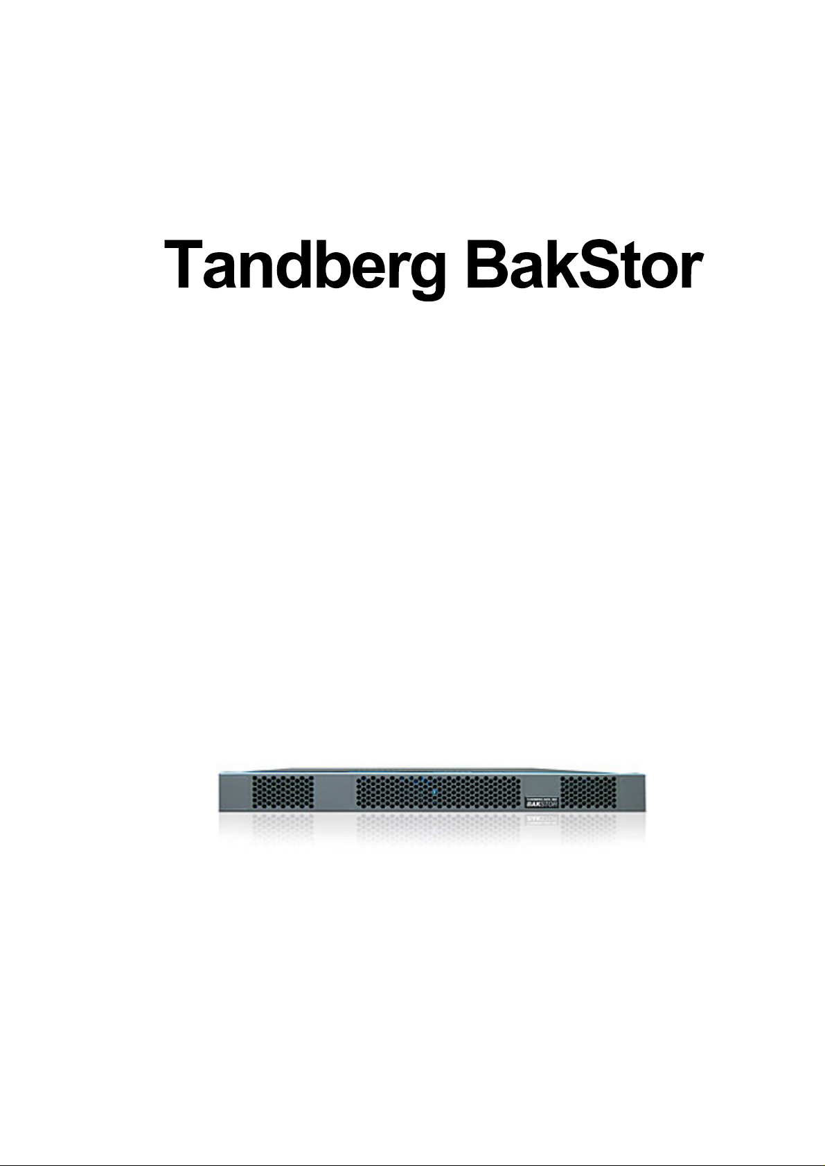
2.3
Figure
Function
Power
Ethernet 0
Ethernet 1
Ethernet 2
Ethernet 3
Ethernet 4
Ethernet 5
Connectors on the Ba
2-2
Connectors on the BakStor 2000
F
P
O
N
M
G
2.3.1 Power
kStor 2000 (2U-Unit)
L
J1
K1
N M
K2
J2
Connector
J1 and J2
Function
External tape device 1 K1
External tape devi
Power Alarm reset
ce 2
L
Connector
K2
Connect the two 3-pin 100/240V AC power cable to positions J1 and J2. (Figure
2-3)
Note that the power supplies are redundant; if one should fail the BakStor will still be able to
operate. In the case of a power supply failure an alarm will bet set off. The alarm can be reset by
pushing button L. (Figure
14
2-4)
BakStor Installation and Administration Manual
Page 17

Tandberg Data
2.3.2 Ethernet 0
Connect the BakStor to the existing LAN by plugging an Ethernet cable to position F. Figure
2-5)
The Ethernet connection can be a 10/100/1000 Mbps to match capabilities of the connecting
LAN.
2.3.3 Ethernet 5
The BakStor also has the ability to manage Fault Tolerance and Load Balancing technology by
using two Ethernet connections.
In order to use Fault Tolerance or Load Balancing a secondary Ethernet cable is required. The
second cable is c
A second Ethernet connection is not required unless Fault Tolerance and / or Load Balancing is
needed. The second Ethernet connection is not required for the initial setup
onnected to position G. (Figure
2.3.4 Ethernet 1 - 4
The four Ethernet connections labeled M, N, O and P (Figure 2-7) are to be used for connecting
BakStor 2000EX expansion units. Do not connect these four Ethernet connections to a LAN.
2-6)
.
2.4
When mounting the BakStor ensure that the unit is oriented correctly.
When viewing a BakStor unit from the front correct orientation is ensured when:
When viewing a BakStor unit from the rear correct orientation is ensured when:
The BakStor is designed to operate in a position where it is lying flat.
Mountin
The blue LED on each disk caddie is located on the RIGHT side of the caddie.
On a BakStor 1
On a BakStor 2000 the powerbutton is located in the LOW and LEFT corner of the front panel.
The power c
The external SCSI controller is located on the RIGHT side of the unit
DO NOT OPERATE A BAKSTOR MOUNTED IN A SIDEWAYS OR
g the BakStor
000 the powerbutton and reset button are located ABOVE the disk caddies.
onnectors are located on the LEFT side of the unit
CAUTION!
POSITION.
UPSIDE DOWN
BakStor Installation and Administration Manual
15
Page 18

Tandberg Data
2.5
The BakStor can be connected to an external tape device or tape library. The external tape
device or tape library is connected to the LVD SCSI controller build into the BakStor. A LVD
SCSI cable is connected to position K1 on the BakStor 1000 (
K2.on the BakStor 2000 (Figure
Note:
and external tape device or tape library is switched off.
Note:
SCSI termination.
Note:
on any SCSI devices connected to the BakStor.
Note:
termination is used.
External Tape Device
2-8)
Ensure that when connecting external SCSI devices that all power from both the BakStor
Ensure that external SCSI devices are connected with proper SCSI cables and proper
The BakStor use SCSI ID number 7. Ensure that a correct and unique SCSI ID
In order to ensure correct behavior and performance ensure that correct SCSI cables and
Figure
2-1) or to position K1 or
is selected
16
BakStor Installation and Administration Manual
Page 19

Tandberg Data
This Page Intentionally Left Blank
BakStor Installation and Administration Manual
17
Page 20

Page 21
3
Configuration
3.1
The BakStor uses SATA disk drives. These are installed in the caddies provided. The BakStor
1U can use up to 4 disk drives and the BakStor 2U up to 12 disk drives.
The BakStor comes with the disks preinstalled in the caddies. Should this not be the case the
disks will need to be mounted in the caddies before they are inserted into the BakStor.
3.2
The BakStor 1U and 2U products come with one or multiple RAID-
3.3
The BakStor 1U and 2U products come with the Ethernet 0
IP address of 192.168.0.6.
Please ensure that this setting will not generate a network conflict on the existing LAN and that
computers on the LAN are capable of communicating with the BakStor at this address.
Failing to ensure this can lead to network problems for the LAN as well as failure to connect to
the BakStor.
Install Disk
RAID Setup
Network Setup
Drive
5 preinstalled.
(connector F) preconfigured with an
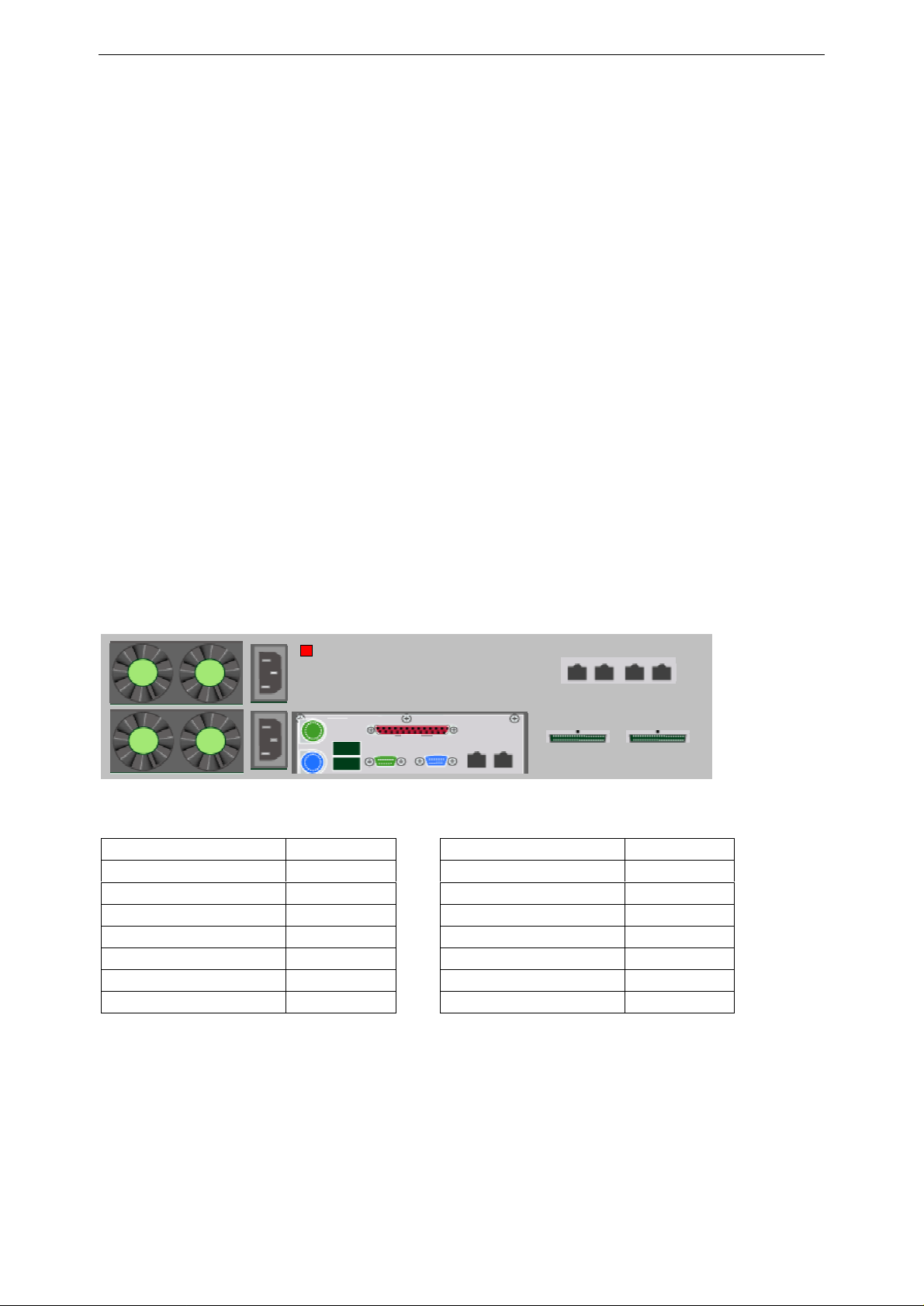
3.4
Press the power switch on the front panel to boot the NAS (
be available at the default IP a
Figure
Power
3-1
Indicators on the BakStor 1U Model
ddress.
Figure
3-1). The unit will boot and
BakStor Installation
and Administration Manual
19
Page 22

Tandberg Data
3.5
In order to connect to the BakStor enter the IP address of the BakStor in an internet browser.
The factor
After connection is established a login dialog box will appear.
The defaults username and password are:
Username: admin
Password: pass
After the username and password have been verified the BakStor Welcome scree
In order to prevent unauthorized access to the BakStor the default password should be changed.
Connecting to the BakStor for the First Time
y set default IP address is 192.168.0.6.
n will appear.
Figure
Note:
frames in your browser please use the link on the BakStor Welcome screen to select using the No Frames version of
the web interface
20
3-2
. BakStor Welcome Screen
The BakStor web interface makes use of inline frames. If you observe problems with displaying the inline
BakStor Installation and Administration Manual
Page 23

Tandberg Data
3.6
The BakStor Unit should always be shut down via the Maintenance menu before switching off
power to the unit. This ensures a correct and clean shutdown.
Choose
As an alternative, if no network connection is available, the unit can be switched off by pressing
the power sw
Note:
shutdown. Keeping the switch pressed turns the power off causing an uncontrolled shutdown.
Press the power switch only briefly to allow the software to perform a controlled
Shutting Down the BakStor
Maintenance
itch on the front panel.
? Shutdown BakStor
Figure
3.7
After connecting to the BakStor one or more RAIDs must be configured.
A RAID (Redundant Array of Independent Disks) makes it possible to configure several disk
drives i
The BakStor has been shipped with a default RAID configuration. Keeping this default RAID
requires no action. Advanced RAID configuration is described in Chapter
In order to view the current RAID set configuration choose
In order to view the current disk drive configuration choose
Note: Accessible capacity
The size of a RAID reported by the BakStor is raw size. Total accessible capacity depends on
operating environme
Note: 2 TB limit
Note that the current version of the BakStor is not able to create a RAID larger than 2TB.
3-3
The BakStor front panel layout with power switch top right
Setting Up a RAID
nto one volume and can be configured to ensure data integrity in the case of disk failure.
nt
RAID Menu
RAID Menu
4.
? View RAID info
? View drive info
.
.
Depending on the capacity of the disks in the BakStor this may mean that not all the disks can
be configured into a single RAID. In this case
3.8
Before the RAID set can be used by the BakStor the RAID set needs to be activated.
Choose
Select the correct RAID to activate from the menu.
Note that already active RAID sets are not listed.
BakStor Installation and Administration Manual
Activating the RAID Storage
RAID Menu
? Add Array to BakStor
multiple RAIDs must be configured.
21
Page 24

Tandberg Data
3.9
A ‘slice’ is similar to a partition. Once a slice is created a computer will be able to access the
slice over the iSCSI network as if it was a local disk drive.
A ‘Virtual Tape’ is a slice that emulates a standard LTO-2 tape drive allowing easy integration
with current backup applications and infrastructures. Once the slice is created a computer will
be able to access the slice as if it was a standard LTO-2 tape drive.
Please consult your system administrator in order to decide which is the most appropriate for
your applications.
3.10 Creating Slices
When creating a slice simply define the name, capacity and whether the slice should be
optimized for Windows or Linux / UNIX operating systems.
In order to create a slice choose
Choosing Slices or a Virtual Tape
Storage menu
? Create a storage slice ? Create a disk slice
The following information needs to be entered:
Slice name. The
Slice size. The size of the slice in MB.
Note:
1 GB (gigabyte) = 1024 MB (megabyte)
1 MB (megabyte) = 1024 kB (kilobyte)
Optimize the slice (Windows/Linux)
Click the ACCEPT button to create the slice.
The screen will refresh and al
name for the slice.
l defined slices will appear on the right side of the screen.
Figure
In order to create a Virtual Tape choose Storage menu ? Create a storage slice ? Create a
virtual tape
22
3-4
. Entering details for a disk slice
BakStor Installation and Administration Manual
Page 25

Tandberg Data
The following information needs to be entered:
Slice name. The name for the slice.
Slice size. This specified the maximum size the virtual tape can reach. Specifying 0
means no limit nd the vir
Click the ACCEPT button to create the virtual tape slice.
The screen will refresh and the virtual tape created will appear on the right side of the screen.
tual slice can grow until the RAID set underneath is full.
Figure
Note:
nearest 10GB. Entering 27000MB, for example, would make the actual size created be
30,000MB.
3-5
. Entering details for a tape slice
Tape Slice is allocated in 10GB blocks, so the size entered will be rounded up to the
BakStor Installation and Administration Manual
23
Page 26

Tandberg Data
This Page Intentionally Left Blank
24
BakStor Installation and Administration Manual
Page 27

Tandberg Data
4
Advanced Configuration
4.1
The BakStor is a disk based product which uses today’s industry approved disk management
(RAID).
The advantages of choosing RAID are: Availability, Capacity and Performance. Choosing the
right RAID level and drive failure management will give the right balance between Availability,
Performance and Capacity.
Before the BakStor can allow disk availability to the user a RAID or logical drive must b
created.
There are various levels of RAID that available with the BakStor:
4.1.1 RAID-0 (Disk Striping)
Choosing a RAID Level
RAID
-0
RAID
-1
RAID-1 + hot spare
RAID
-5
RAID-5 + hot spare
Disk striping
Disk Mirroring
Disk Mirroring with dedicated ‘hot spare’ disk drive.
Multiple Block Striping with Interspersed Parity
Multiple Block Striping with Interspersed Parity and with
Dedicated ‘hot spare’ disk drive
e
A RAID-0 allows multiple disks to be combined to create one large volume.
Performance is greatly improved since all the disks are accessed in parallel and is considered to
be the fastest way to access multiple disks drives.
A RAID-0 offers no protection against disk failure. If a single disk in the RAID-0 set should
fail, the entire RAID set will fail.
If your environment depends on quick data access and less on protecting against disk drive
failure RAID-0 would be the best option.
Example:
In the BakStor there are 4 x 250GB capacity disk drives. By creating a RAID-0 one single
logical drive with a size of 1000GB will be available instead of four single 250GB drives.
(4 x 250GB =1000GB usable)
Often RAID-0 is used for non-critical data that may only be an archive or second copy of data
that is not accessed regularly and may be held for a short period.
2 TB limit
Note that the
Depending on the capacity of the disks in the BakStor this may mean that not all the disks can
BakStor User Manual
current version of the BakStor is not able to create a RAID larger than 2TB.
25
Page 28

Tandberg Data
be configured into a single RAID
For instance, with a disks size of 400GB, only
In order to utilize all disks in a BakStor 2000, several RAID sets are needed.
4.1.2 RAID-1 (Disk Mirroring)
-0.
5 disks can be configured in a RAID-0 set.
If your environment is more critical to data protection, RAID-1 offers protection against disk
failure.
In a
mirror is then written to both disk drives.
RAID
-1 two disk drives are combined into a mirror configuration. All data written to the
The upside to a RAID-1 configuration is that should one disk drive fail the second disk drive in
the mirror contains an ide
ntical mirror of the data.
The downside to a RAID-1 is the wastefulness of disk drives. Two disk drives are combined to
offer the disk space of only one disk drive.
Note that a RAID-
1 setup will provide a RAID set that has the size of a single disk drive
even if
more than two disk drives are specified for the RAID set. Specifying more than two disk drives
will simply give multiple mirrors. For instance, specifying a RAID-1 with four disk drives will
give a RAID set with four identical disk drives.
Example
:
In the BakStor there are 2x 250GB capacity disk drives. By creating a RAID-1 one single
logical drive with a size of 250GB will be available instead of two single 250GB drives.
(2x 250GB – 1 x 250GB for mirror =250GB usable)
RAID-1 + hot spare (disk mi
RAID
-1 + hot spare has the same instances as RAID-1 except it has a dedicated hot spare drive
rroring with dedicated replacement drive)
that is not part of the Logical drive but stands by in case of a drive failure.
In the case of a drive failure in one of
the two RAID-1 drives the BakStor will immediately start
the process of mirroring the data to the hot spare drive.
RAID-1/RAID
comes second to data security and availability.
-1 + hot spare are in use in critical access data applications, where capacity
4.1.3 RAID-5 (Multiple Block Striping with Interspersed Parity)
In today’s data environment there is a fine balance between cost, protection and transfer speed.
In some cases transfer speed can be slightly compromised against cost and protection. RAID-5
offers a good cost effective solution with high level of protection but without the costs incurred
in mirroring solutions. RAID-5 creates a multiple block striping with interspersed parity
enabling a security level that will allow access to the logical even if a drive fails. Obviously
because of this calculation, data access time can affect the overall performance of the logical
drive, but adversely the failed drive can be replaced and rebuilt using this interspersed parity to
recalculate and rewrite the missing drives information giving a high level of data protection.
Using the examples above the capacity is compromised, in comparison to the RAID-0 but is not
26
BakStor Installation and Administration Manual
Page 29

Tandberg Data
as compromised as RAID
Example
In the BakStor there are 4 x 250GB capacity disk drives. By creating a
with a size of 750GB will be available instead of four single 250GB drives.
-1.
RAID-5 one logical drive
(4 x 250GB – 1 x 250GB for parity =750GB usable)
RAID-5+hot spare (Multiple Block Striping with Interspersed Parity and dedicated spare drive)
RAID
-5 + hot spare has the same instances as RAID5 except it has a dedicated hot spare drive
that is not part of the Logical drive but stands by in case of a drive failure.
In case of a drive failure the BakStor will immediately start the process of incorporating the
spare drive into the RAID
Typically RAID-
5/RAID
today’s industry environments.
2 TB limit
Note that the current version of the BakStor is not able to create a RAID larger than 2TB.
-5.
-5 + hot spare are the most popular cost effective RAID level used in
Depending on the capacity of the disks in the BakStor this may mean that not all the disks can
be configured into a single RAID.
For instance, with a disks size of 400GB, only 6 disks can be configured in single RAID 5 set.
In order to utilize all disks in
4.1.4 Shared hot spare drive
a BakStor 2000, several RAID sets are needed.
On a BakStor 2000 there are enough disk drives (12) to create multiple RAID sets. In order to
cut down on the number of disk drives used as hot spare drives it is possible to configure a disk
drive as a “shared spare drive”. This way one single disk drive can act as a hot spare for
multiple RAID sets. In the case of a failure in one RAID set the shared spare drive will be used
in this RAID set. If there is a failure in the second RAID set as well there will be no spare drive
available for the second RAID set and it will run in degraded mode until the faulty disk in the
second RAID set has been replaced.
BakStor Installation and Administration Manual
27
Page 30

Drive Slot 10
Drive Slot 11
Tandberg Data
4.2
When creating a RAID it is vital for the system administrator to be familiar with the respective
disk drive positions. This is even more important for fault diagnosis to ensure that the incorrect
drive is not removed during replacement of a faulty drive.
The disk drive locations on the 1U and 2U are as shown:
Drive Slot 0
Figure
Drive Slot 0
Creating a RAID
Drive Slot 1
4-1
1U Drive Positions
Drive Slot 1
Drive Slot 2
Drive Slot 2
Drive Slot 3
Drive Slot 3
Drive Slot 4
Dr
ive Slot 8
Figure
In order to create a RAID set choose
The following information is needed:
4-2
2U Drive Positions
Desired RAID level
Disk drives to be included in the RAID
Click the ACCEPT button to start the process of creating the RAID.
Drive Slot 5
Drive Slot 9
Drive Slot 6
RAID Menu
? Create a RAID
Drive Slot 7
28
BakStor Installation and Administration Manual
Page 31

Tandberg Data
Figure
In order to check the status of the RAID creation, choose
Note the screen has to be manually refreshed to update status.
building the status will be shown as online.
4-3
. Creating a RAID
RAID Menu
? View RAID info
When the RAID has finished
.
Figure
BakStor Installation and Administration Manual
4-4
. Status of a RAID during building
29
Page 32

Tandberg Data
4.2.1 Activate newly build RAID
After a RAID has finished the building process it has to be activated before it can be put to use
and before slices can
Choose
Choose the correct RAID to activate and click the ACCEPT button.
At this point the RAID is available for new slices. See Section 3.10 for details on configuring
slices.
4.3
In the case of a disk drive failure, the RAID info screen will display information regarding the
failure.
Choose
be created on top of the RAID.
RAID Menu
? Add array to BakStor
RAID Failure
RAID Menu
? View RAID info
in order to activate the new RAID.
Figure
Information on the exact disk drive that has failed can be found in the drive info menu.
Choose
The failed disk drive will be displayed with a status of “no-response”. Make a note of the slot
number of the
4-5
Status sho
RAID Menu
failed disk drive.
wing a degraded RAID
? View drive info
30
BakStor Installation and Administration Manual
Page 33

Tandberg Data
Figure
failed.
4-6 Disk status showing a failed disk in the RAID. In this case the disk in slot 0 has
4.3.1 Repairing a RAID
First the failed disk drive needs to be remov
To configure the BakStor to expect a faulty disk drive to be removed, choose RAID menu
Repair a RAID
All currently failed disk drives will appear in the Select slot pull-down menu.
Choose the disk drive to be removed and click the ACCEPT button.
? Remove faulty drive
ed from the BakStor.
?
Figure
Once accepted, it is safe to physically remove the faulty drive. Take great care to ensure that the
disk drive is removed from the correct hardware slot position.
BakStor Installation and Administration Manual
4-7
Selecting a faulty disk drive to be removed
31
Page 34

Tandberg Data
Once the failed disk drive has been removed insert the replacement disk drive.
After installing the replacement disk drive the BakStor must be configured to make use of the
new disk drive.
Choose
Caution!
Ensure that the
Removal of incorrect disk drive will cause data to be permanently lost.
RAID Menu
? Repair a RAID ? Scan for drives
correct disk drive is removed.
Figure
The replacement disk drive can then be configure
For a BakStor 1000, choose
For a BakStor 2000, choose
4-8
Replacement disk drive detected
RAID Menu
RAID Menu
? Repair a RAID ? Add spare drive to RAID
? Spare drive menu ? Add spare drive to RAID
d into the RAID.
32
BakStor Installation and Administration Manual
Page 35

Tandberg Data
Figure
Notice that only disk drives currently not assigned to any RAID will appear in the Select drive
slot pull-down menu.
4-9
Selecting a disk drive to be inserted into the RAID
Once the new disk drive has been successfully added to RAID the rebuild process will start
automatically. The progress of the rebuild process can be monitored in the “view RAID Info”
and “view drive info” screens.
BakStor Installation and Administration Manual
33
Page 36

Tandberg Data
4.3.2 Deleting a RAID
Before deleting a RAID ensure that all data has been removed from the slices located on the
RAID set.
Deleting a RAID set will cause any data on the RAID set to be permanently lost.
Then delete any disk slice or virtual tape slice located on the RAID set. Choose Storage Menu
? Delete a storage slice
The name of the slice must be entered twice to confirm. Click the ACCEPT button to delete the
slice.
Caution!
and choose the slice(s) to delete.
To delete a RAID choose
Choose the correct RAID set to delete and choose “Yes” for “Are you sure”.
Then click the ACCEPT button to delete t
RAID Menu
? Delete a RAID
he RAID.
Figure 4-10
34
Confirming the intention to delete a RAID
BakStor Installation and Administration Manual
Page 37

Tandberg Data
4.4
A snapshot makes it possible to take a point-in-time image of a disk slice. It is not a full copy of
the disk slice, rather it is an image of what the disk slice looked like at the moment the snapshot
was taken. As the original disk slice is modified the snapshot can be used to "go back in time" to
the time the snapshot was taken. A snapshot can be exported and mounted on an iSCSI initi
computer just like a regular disk slice. The snapshots on a BakStor are both readable and
writeable.
Since the only disk space used by a snapshot is the parts of the slice that has changed on either
the original slice or the snapshot, the snapshot and the original slice share the majority of the
disk space.
However, as the difference between the original slice and the snapshot increases the amount of
space used for the snapshot will increase. If the BakStor runs of space to accommodate the
growth of a snapshot the snapshot will become unavailable. The BakStor will intelligently
allocate space for the snapshot on the RAID sets most suitable.
The BakStor has two methods for Snapshots: Scheduled and Instant
Snapshots
ator
4.4.1 Creating Instant Snapshots
To create an instan
The following information must be provided:
Slice name
Snapshot size. This is the amount of disk space the snapshots starts with. The size is
specified as a percentage of the slice to take snap
slice of size 500GB and 10% is specified 50GB will initially be reserved for the
snapshot.
Snapshot name. If the snapshot name is not defined the slice
used as the name of the snapshot
Then
click the ACCEPT button to create the snapshot.
t snapshot, choose
. The slice to take a snapshot of.
Snapshot
? Create a snapshot
shot of. If taking a snapshot of a disk
-name date and time will be
BakStor Installation and Administration Manual
35
Page 38

Tandberg Data
Figure 4-11
4.4.2 Scheduling Snapshots
Snapshots can also be scheduled to run at a given time.
To create a s
The following information will be needed
Configuring an instant snapshot
cheduled snapshot choose
Slice name.
Snapshot size. This is the amount of disk space the snapshots starts with. The size is
specified as a percentage o
slice of size 500GB and 10% is specified 50GB will initially be reserved for the
snapshot.
Snapshot name.
as the n
The hour the snapshot will be taken.
The day in the month the snapshot will be taken
The slice to take a snapshot of.
f the slice to take snapshot of. If taking a snapshot of a disk
If the snapshot name is not defined the slice-name date and time will be used
ame of the snapshot
Snapshot
? Schedule a snapshot
The month the snapshot will be taken
The snapshot schedule has now been set and will take place at the scheduled time/day/month.
36
BakStor Installation and Administration Manual
Page 39

Tandberg Data
Figure 4-12
If the snapshot name is not defined the slice-name date and time will be used as the name of the
snapshot
Configuring a scheduled snapshot
BakStor Installation and Administration Manual
37
Page 40

Tandberg Data
4.5
In addition to making a single snapshot (either instant or scheduled) the BakStor has an option
for scheduling multiple snapshots to be scheduled.
The BakStor’s ‘AiiR’ module contains a snapshot scheduler that can configure and run up to
100 snapshots.
To set up an AiiR schedule choose AiiR
Info to enter:
Slice name. The slice to take a snapshot of.
Snapshot capacity. The amount of space allocated for the AiiR process. Defined as
percent of the size of the slice to be taken snapshots of.
Number of rotations.
Start at time. The hour when the first snapshot in the schedule will be taken.
Interval (hours/minutes). Time between the snapshots in the schedule.
Skip between repetitions. Time between repetitions of the schedule
Repeat
Creating an AiiR Process
? Create an AiiR process
Number of snapshots to be taken.
. Specify if the AiiR process repeat itself once completed
Click the ACCEPT button.
Figure 4-13
The figure shows an example configuration for a 7-day cycl
The first snapshot is taken at 20:00 hours on the first day
The process repeats for 5 cycles (in this case there are 24 hours between the snapshots). There is
then a skip of the next 48 hours (2 days), and then the sch
38
Configuring an AiiR process
e. The schedule uses five snapshots.
edule starts again.
BakStor Installation and Administration Manual
Page 41

Tandberg Data
4.5.1 Starting an AiiR Process
After having defined an AiiR process, the process must be started.
Choose AiiR
Info to enter:
Slice name. The name of the slice for which the AiiR process has been defined.
Click the ACCEPT button.
Note: While an AiiR daemon is running the BakStor will monitor for free disk space available
for the daemon. If more than 75% of the space allocated for the AiiR snapshots is used, the
BakStor will automatically attempt to increase the snapshot space by 1GB. If there is not
enough free disk space to increase the snapshot space the AiiR daemon will fail and no further
snapshots will be made.
? Start an AiiR process
BakStor Installation and Administration Manual
39
Page 42

Tandberg Data
4.6
The BakStor 1U and 2U products both support secure authentication (CHAPs). This allows to
set password protection on both the BakStor unit and also on individual slices and virtual tap
4.6.1 Setting a Password for the BakStor
Setting a username and a password for the entire BakStor will prevent iSCSI initiators that do
not have the username and password from connecting to the BakStor.
In order to set secure authentication for the BakStor unit choose Storage menu ? Access
control
The following information is required:
Username. Using the name of the computer intended as the iSCSI initiator will help in
the administration of the iSCSI network.
Password
Adding Secure Authentication (CHAPs)
? Set AC for BakStor
es.
Click the ACCEPT button to activate the changes.
Figure 4-14
Note:
chara
cters with no space
Configuring username and password for iSCSI login to the BakStor
Microsoft secure authentication requires that the password must have between 12 and 16
40
BakStor Installation and Administration Manual
Page 43

Tandberg Data
4.6.2 Setting a Password for an Individual Slice
Instead of or in addition to restricting access to the entire BakStor access control can be
configured for each defined slice.
This allows for even greater control over what iSCSI initiators can access a given resource on
the BakStor.
In order to set secure authentication for an individual slice choose Storage Menu ? Access
control
The following information is required:
Slice name
User name. Using the name of the co
the administration of the iSCSI network.
Password
? Set AC for a defined slice
mputer intended as the iSCSI initiator will help in
Figure 4-15
BakStor
Note:
characters with no space
BakStor Installation and Administration Manual
Configuring username and password for iSCSI login to an individual
Microsoft secure authentication requires that the password must have between 12 and 16
.
slice on the
41
Page 44

Tandberg Data
This Page Intentionally Left Blank
42
BakStor Installation and Administration Manual
Page 45

Tandberg Data
5
Connecting and Using External Units
5.1
The BakStor Expansion Unit allows for more storage space to easily be added to the BakStor
solution. The BakStor Expansion Unit is a 2U unit with 12 internal disk drives that compliments
the BakStor 2000. In such a configuration the BakStor 2000 will be referred to as a BakStor
Master Unit.
The BakStor Expansion Unit connects to the BakStor Master Unit by the use of a crossover
Ethernet cable. This means that no new connection to the network is required. The BakStor
Expansion Unit is managed from the same web interface and IP address that is used to manage
the existing BakStor 2000.
Note that a dedicated Ethernet port is needed on the BakStor Master Unit for the BakStor
Expansion Unit.
Multiple BakStor Expansion Units can be connected to a BakStor Master Unit by dedicating
multiple Ethernet ports on the BakStor Master Unit, one Ethernet port for each BakStor
Expansion Unit.
Connecting a BakStor Expansion Unit
5.1.1 Preparing the BakStor Master Unit
Before connecting the BakStor Expansion Unit the current BakStor 2000 must be configured to
act as a BakS
Make sure that the firmware version running on the BakStor 2000 is capable of acting as a
BakStor Master Unit.
Choose
The firmware version should end in “_master” in order to be an BakStor Master Unit.
Also
verify that the top level menu option BakStor EX
An internal network will be configured between the two units, so the BakStor Master must have
at least one available Ethernet port.
In order to configure the chosen Ethernet port as an Expansion
Configuration
From the menu choose the port to be configured as an Expansion port. Then click the ACCEPT
button.
Note that any port already configured as Expansion ports are not available from the menu.
tor Master Unit.
Maintenance
? Network configuration ? Set Expansion port
? Show license info
is present.
Port, choose
5.1.2 Connecti
Use the crossover cable that came with the BakStor Expansion Unit and connect Ethernet port 0
on the BakStor Expansion Unit to the correct Ethernet port on the BakStor Master Unit.
The Ethernet port on the BakStor Master Unit
BakStor User Manual
ng the BakStor Expansion Unit
must have been configured as an Expansion port.
43
Page 46

Tandberg Data
Ensure that the BakStor Master Unit is powered on and then power up the BakStor Expansion
Unit.
When both units are running they will negotiate the settings to form a private network.
The BakStor M
5.1.3 Detecting and Configuring the BakStor Expansion Unit
In order to configure the BakStor Expansion Unit use the menu on the BakStor Master Unit and
choose
Caution!
aster Unit and the BakStor Expansion Unit must be connected by the
means of an Ethernet crossover cable only.
Do not attempt to use an Ethernet switch or hub between the two units
BakStor EX
This will probe for BakStor Expansion Units on all Ethernet port previously defined as
Expansion Ports.
All discovered BakStor Expansion Units will be listed with the Ethernet port number to which
they are connected.
Once
the BakStor Expansion Units are discovered they can be configured with RAID sets.
Choose BakStor EX
Then select the BakStor Expansion Unit to configure and click on the link in order to connect to
the specified BakStor Expansion
Once the web interface of the BakStor Expansion Unit has loaded choose
RAID Menu
This will show any RAID that already may exist.
If a new RAID set has to be created choose
The RAID configuration menu for the BakStor Expansion Unit is identical to the RAID
configuration menu for the BakStor Master Unit and the BakStor 2000. See Section 4.2
details on configuring a RAID.
? Discover BakStor EX’s
? Config / View BakStor EX
Unit.
? View RAID info
RAID Menu
? Create a RAID
.
for more
5.1.4 Activating RAID Sets on BakStor Expansion Unit
Aft
er configuring the desired RAID sets on the BakStor Expansion Unit choose
BakStor
To activate the new RAID choose
BakStor EX
A list of RAID sets available will be listed. Choose the correct RAID to activate and click the
ACCEPT button.
44
to move back to the web interface for the BakStor Master Unit.
? Attach / Detach EX storage
BakStor Installation and Administration Manual
Master
Page 47

Tandberg Data
The RAID will now be available for creating disk and virtual tape slices. The disk and virtual
tape slices are created from the web interface for the BakStor Master Unit. The process is
identical to the normal process of creating slices. The RAID sets located on the BakStor
Expansion Unit will be available just like RAID sets located on the BakStor Master Unit.
Note:
Once slices have been defined on the RAID sets located on the BakStor Expansion Unit
the unit can no longer be detached from the BakStor Master Unit. If detachment is required the
slices must be deleted. All data located on the slices will be lost.
5.1.5 Powering
Once slices have been created on the BakStor Expansion Unit it is an integrated part of the
BakStor and cannot independently be powered down.
If it is required to power down the BakStor Expansion Unit (for example in order to physically
relocate it) both the BakStor Expansion Unit and the BakStor Master Unit must be powered
down.
In this case it is recommended to power down the BakStor Expansion Unit first, then power
down the BakStor Master Unit. It is strongly recommended to
menu system to shut the units down.
down a BakStor Expansion Unit
use the power-down option in the
If it is required to permanently remove a BakStor Expansion Unit all slices located on the
BakStor Expansion Unit must be deleted. All data located on these slices will be lost.
Choose
Expansion Unit
Choose Storage menu ? Delete a storage slice
BakStor Expansion Unit
Note: All data located on these slices will be lost
Cho
located on the BakStor Expansion Unit.
At this point the BakStor Expansion Unit can be powered down and removed.
Powering down or disconnecting a BakStor Expan
Storage Menu ? View slice location
ose
BakStor EX
? Attach / Detach EX storage
will cause the BakStor Master Unit to be non-operational
to observe what slices are located on the BakStor
to delete the slices that are located on the
. Then click on “detach” for the RAID sets
Caution!
sion Unit that has attached RAID sets
5.1.6 Failover Ethernet for Expansion Unit
The BakStor Expansion Unit is provided with two Ethernet connections. By using a second
crossover cable the connection between the BakStor Master Unit and the BakStor Expansion
Unit can be configured for failover (AFT).
Configure the BakStor Expansion Unit first, then the BakStor Master Unit.
1. Using the web interface for the BakStor Expansion Unit, choose
BakStor Installation and Administration Manual
Configuration
?
45
Page 48

Tandberg Data
Network configuration
Select Adapter Fault Tolerance (AFT) and click the ACCEPT button.
Note:
not a problem. When the BakStor Master Unit is completely configured the connection will
be reestablished.
Note:
Do not attempt to configure any other failover mode.
2. Using the web interface for the BakStor Master Unit, choo
Network configuration
Select the port currently assigned as an Expansion port for the given BakStor Expansion
Unit. Click ACCEPT.
3. Choose
Select the two ports that are to form the AFT link to the BakStor Expansion Unit. Then
select AFT as the mode. Click ACCEPT and ignore any error messages.
? Global Configuration
At this point the connection to the BakStor Expansion Unit may be disrupted. This is
Only Adapter Fault Tolerance (AFT) is supported for the second Ethernet connection.
se
Configuration
? Remove Expansion Port
Configuration
? Network configuration ? Create a team
?
4. Choose
Select the team port from the list of ports and click the
5. Choose
Study the information frame on the right. At the bottom of this frame there is a list of all
team ports. Locate the newly created team and
Make sure that the current crossover cable is connected to this port. (And not the other port
in the team). If the current crossover cable is connected to the Secondary port move the
cable to it is connected to the Primary port)
6. Choose
The BakStor Expansion Unit should be listed. If not listed rerun the discovery
7. Choose BakStor EX
Click on the link provided and connect to the BakStor Expansion Unit. Wait for the web
interface for the Bak
8. From the menu on the BakStor Expansion Unit choose
configuration
The ports should be listed as being in Fault Tolerance Mode.
Make a note of what port is listed as Primary port. Ensure that the current crossover cable
is connected to this port. If the current crossover cable is connected to the Secondary port
move the cable to the Primary port and go back to step 6.
Configuration
Configuration
BakS
tor EX
? IP configuration
? Discover BakStor EX’s
? Config / View BakStor EX
Stor Expansion Unit to load.
? Network configuration ? Set Expansion Port
ACCEPT button.
? Network configuration ? Change IP configuration
make a note of what port is lis
Configuration
ted as Primary.
? Network
9.
When the crossover cable is confirmed connected to the correct port on
Master Unit and the BakStor Expansion Unit connect the second crossover cable. This
cable is to be connected between the second port defined to be a member of the team on
the BakStor Master Unit and the remaining port on the BakStor Expans
At this point the connection between the BakStor Master Unit and the BakStor Expansion Unit
will be in Adapter Failover Mode. This allows for the failure of one cable between the two units.
Choose
Master Unit and the BakStor Expansion Unit.
46
BakStor EX ? Discover BakStor EX’s
to verify the connection between the BakStor
BakStor Installation and Administration Manual
both the BakStor
ion Unit.
Page 49

Tandberg Data
Should one of the Ethernet cables be disconnected the other cable will be used for
communication between the two units. The failover will be transparent to any iSCSI initiators
conn
ected to the BakStor.
BakStor Installation and Administration Manual
47
Page 50

Tandberg Data
5.2
The BakStor unit can be connected to an external SCSI tape device using the SCSI connections.
This allows for moving data from the BakStor for offsite or archival storage. Standalone tape
drives, ta
5.2.1 Connecting and Configuring a Stand-Alone Tape Device
In order to use an external tape device it first needs to be connected to the BakStor:
1.
Power down the BakStor.
2.
Connect the external tape device to the SCSI port on the BakStor. Make sure that proper
SCSI cables and SCSI termination is used.
3.
Power up the external tape device.
4.
Power up the BakStor.
Using an External Tape Device
pe libraries and autoloaders can be used.
The tape device is now connected to the BakStor. Verify that the SCSI tape device was correctly
recognized by the BakS
Choose
This will provide a list of all tape devices recognized by the BakStor. If a tape library is
connected a tape map of the library will be displayed as well.
If the tape device is
rescan the SCSI bus.
If the tape device is still not recognized power down the BakStor and check the SCSI cables and
the SCSI termination on the SCSI bus.
Backup Menu
5.2.2 Formats for moving data to
The BakStor can be used to move both diskslices and tapeslices to a physical tape.
For diskslices a direct blocklevel copy of the data from the slice to the physical tape is
performed. The data can be restored from the physical tape to a
The data can be moved back to any BakStor unit should the original BakStor unit not be
available.
tor.
? Tape control menu ? Scan for new tape device
not r
ecognized
select yes and click the accept button to force the BakStor to
a physical tape
diskslice on the BakStor.
The BakStor does have an option for encrypting the data before copying the data to a physical
tape. If this option is used a password will be required before data can be copied from the
physical tape.
For tapeslices (Virtual Tapes) there are two options for what format to use when copying data
from the slice to the tape.
The data can either be copied in
Native mode creates a physical tape that is native to the BakStor. This creates a physical tape
48
native
mode or in
application mode.
BakStor Installation and Administration Manual
Page 51

Tandberg Data
that can only be restored on a BakStor unit. As with diskslices the data can be encrypted before
it is copied to the physical tape.
Application mode creates a physical tape in a format of the application that was used to write to
the Virtual Tape. Most backup software use a proprietary format when writing to a physical
tape. Using the application mode allows the BakStor to create a physical tape that uses
proprietary format.
this
A physical tape created in application mode can be restored on any computer that is fitted with a
physical tape drive capable of reading from the physical tape and backup software capable of
reading the format used by the original
backup software.
Note that a physical tape created in application mode cannot be restored back to a BakStor unit.
The physical tape can only be restored on a computer with the correct backup software and a
correct physical tape drive.
5.2.3 Selecting encryption
method for moving data to physical tape
When copying a slice to physical tape the data may be encrypted. Different encryption
algorithms are available for the data encryption.
Choose
Th
Configuration -> Encryption configuration -> Select encryption method
e different algorithms available are:
RC2
Blowfish
CAST
CAST5
DES
Tripple-DES
RC4
BakStor Installation and Administration Manual
49
Page 52

Tandberg Data
5.2.4 Checking contents of a physical tape
Before using a tape for backup purposed the contents of the tape should be checked.
This prevents accidentally overwriting a tape contai
Choose
If the tape has previously been used to back up a slice from the BakStor the name of the slice
will be displayed.
5.2.5 Defining a backup policy
Choose
The following information needs to be entered:
Slice name. Specify the slice to be backed up.
Do snapshot yes/no. If selected, the BakStor will make a snapshot of the slice to be
backed up before starting the backup process. The snapshot
and deleted once the copy process is done. This allows the slice to stay online and be
used by an iSCSI initiator during the tape backup process. Any changes made to the slice
after the snapshot is made will not be backed up to
easier to control the state of the slice when it is copied to tape.
Backup Menu
Backup menu
ning data that should be saved.
? Restore menu ? Check tape contents
? Defin
e / Redefine a BP
the tape, but this option makes it
will then be copied to tape
Tape drive. In the case of multiple tape drives this allows a specific device to be used for
the backup job.
Library slot. In the case of a tape library
used. The BakStor will communicate with the library to ensure that the tape from the
correct slot is loaded for the job.
Click the ACCEPT button to activate the BP
Note: There are some restrictions on back
1.
Only one slice can be backed up to one physical tape.
2.
The slice must be equal to or smaller than the physical tape. The BakStor will not
span physical tapes. (This restriction includes spanning tapes in a tape library)
3.
The BakStor
accessing the file system created by the iSCSI initiator and as such cannot perform a
file level backup. This means the entire slice will be backed to tape, even if the slice
contains
4.
If a diskslice is backed up to the tape containing the backup can only be restored on a
BakStor unit.
5.
If a tapeslice is backed up and “native mode” is selected the tape containing the
backup can only be restored on a BakStor unit.
6.
If a tapeslice is backed up and “application mode” is selected the tape containing the
backup can not be restored on a BakStor unit, but must be restored on a computer
outfitted with a correct physical tapeunit and correct backup software.
performs a block level backup of the slice. The BakStor has no means of
little or no actual data.
this allows a specific slot in the library to be
ing up to physical tape:
50
BakStor Installation and Administration Manual
Page 53

Tandberg Data
Figure
Once the backup policy has been defined, it can be run immediately or scheduled to run at a
later time.
5-1
. Configuring a backup policy
To run the backup immediately, choose
Then choose the name of the slice to be backed up. Click the ACCEPT button to start the
backup.
Figure
5-2
Starting a defined backup
Backup Menu
? Ru
n a defined backup now
.
BakStor Installation and Administration Manual
51
Page 54

Tandberg Data
5.3
To schedule a backup policy (BP) choose Backup Menu ? Perform Backup ? Set / Change
schedule backup
The following information will be needed:
Slice name. Only slices that already have a backup policy listed are candidates for
backup scheduling.
Backup at (time). Specify the time for the backup.
Date (day). Specify the day in the month for the backup
Date (month). Specify the month for the backup
Repeat. The backup can be specified to run once or be repeated. For repeat backup jobs
there are several options for the repeat interval:
Scheduling a Backup
Hourly. The job
Daily. The job is run every day at the hour and minutes specified
Weekly. The job is run every seventh day, starting at the date and time specified.
is run once every hour at the minutes past full hour specified.
Monthly. The job is run once a month at th
Click the ACCEPT button to activate the changes.
Note:
With repeat jobs the backup job will use the tape present in the drive or library slot
specified. No check will be done to verify if the tape contains data and any data already on the
tape will be overwritten.
The backup schedule has now been created with start at the entered time/day/month.
e date and time specified.
Figure
52
5-3
Configuring a scheduled backup
BakStor Installation and Administration Manual
Page 55

Tandberg Data
5.4
After a successful backup to a physical tape the data can be restored should there be a need for
it. The BakStor offers two different ways to restore from a tape, depending on whether or not
the original slice still exists.
If the slice does ex
on the physical tape.
If the slice is no longer available on the BakStor or there is a need to restore the data on a
different BakStor unit it is possible to recreate the enti
5.4.1 Restoring data to a slice from a Physical Tape
In order to restore data to a slice from a physical tape select the slice to restore to. Choose
Backup Menu
Restoring from a Phy
ist the BakStor can overwrite the current data on the slice with the data stored
? Restore Menu ? Restore by slice name
sical Tape
re slice from physical tape.
.
This will replace the data o
If a contents check is needed for the physical tape choose Backup Menu ? Restore Menu ?
Check tape contents.
This will list the name of the slice contained on the tape. Do not use the “restore this slice” link
as this is used for restoring the entire slice, not just the data.
n the slice with the data on the physical tape.
Figure
Note: There are some restrictions on restorin
BakStor Installation and Administration Manual
5-4
Restoring data from a physical tape to an existing slice
1.
Only restore the backup from tape to the same slice the backup was made from.
Attempting to restore the data to a different slice may cause the slice to be corrupted.
2.
The original slice must exist and be available. If the origi
procedure for restoring a slice must be used.
g data from a physical tape:
nal slice is deleted the
53
Page 56

Tandberg Data
5.4.2 Restoring a slice from a Physical tape
To restore a slice that no longer is present on the BakStor unit choose Backup Menu ->
Restore Menu -> Check tape contents
This shows the name of the slice located on the physical tape. A link labeled “restore this slice”
will be available. This restore process will generate a slice with the name of the slice on tape
and restore the data to this slice.
Note:
There are some restrictions on restori
1. When restoring a slice from a physical tape the original slice or a slice with the same name must
not be present. The presence of a slice with the same name as the slice on the tape will cause the
restore process to fail
2. There
must be sufficient space on the BakStor to allow the slice to be created.
ng data from a physical tape:
54
BakStor Installation and Administration Manual
Page 57

Tandberg Data
6
Configuration Options
All models of the BakStor have at least two network ports. Some models may be equipped with
more than two ports.
These network ports can be configured in
The BakStor can be configured to allow connections on different networks; it can be configured
for distributing the load over a number of network connections; it can be configured to allow
failover between network connections; its can be connected to BakStor EX units to increase the
storage capacity.
6.1
The global configuration menu allows configuring the mode of the network connections.
Choose
a number of various modes.
Global Network Configuration
Configurati
on
? Network configuration ? Global configuration
BakStor name. The iSCSI Target name used to identify this BakStor. In a setup with multiple
BakStor units it is recommended that each unit be given a unique name.
MODE Normal - In this mode both network ad
and so can operate on different networks
AFT – (Adapter fault Tolerance) Only one network adapter is active at a time. If the
Primary connection fails, the secondary takes over.
ALB – (Adaptive Load Balancing)
adapters.
802.3ad – (Intel Link Aggregation) All adapters simultaneously transmit and receive
data. This includes fault tolerance and load balancing. Requires a switch that supports
Intel Link Aggregation, Cisc
Jumbo –
used if these frame sizes are supported by other hosts on network.
network administrator before emnabling Jumbo f
o Fast Ether Channel or Static 802.3ad.
Allows larger frame sizes to be used on network. Jumbo frames can only be
apters can have different network addresses
The transmission load is shared amongst both
rames.
Please consult your
BakStor Installation and Administration Manual
55
Page 58

Tandberg Data
6.2
Choose
This allows the IP address of the different network connections on the BakStor to be configured.
IP Configuration
Configuration
? Network configuration ? IP configuration
Figure
6-1
Configuring IP a
ddress and settings
56
BakStor Installation and Administration Manual
Page 59

Tandberg Data
6.3
This menu allows for configuration of some system settings for the BakStor.
6.3.1 Setting a Password for the Administrator
This allows for setting and changing the password used to access the HTTP interface of the
BakSto
Choose
Enter the new password 2 times and click the ACCEPT button.
Note that the password needs to be between 4 and 16 characters and can only include the
characters [aA –zZ] and [0 –9]
6.3.2 Setting the System Time
Choose
r
System Configuration
Configuration ? Administrator Settings
Configu
ration
? Set Date/Time
The BakStor products use an internal clock that display time in UTC (Universal Time
Coordinates). When setting the clock ensure that correct time is entered in UTC.
6.3.3 Setting an Email Address for Notifications
The BakStor can be configured to send emails for system events.
Choose
The following information is needed:
Emails can be configured to be send for all system events (Always), just system failures
(Failure) or never (Never)
Configuration
Email address of the recipient
Address of a server that will accept SMTP requests
Port number that the mail server will accept SMTP re
Email sender, an email alias for the BakStor. This can help the reception when setting up
mail filters etc.
? Set Email notification
quests on
BakStor Installation and Administration Manual
57
Page 60

Tandberg Data
6.4
6.4.1
Choose
The iSCSI service is the service running on the BakStor that is responsible for exporting the
defined slices. The service is automatically started when the BakStor starts, this menu options
allows the se
6.4.2 Stopping the iSCSI Service
Choose
This option allows for a stop of the iSCSI service without shutting the BakStor down. iSCSI
service is stopped the slices can no longer be accessed from an iSCSI initiator, but the
webinterface is still accessable
S
iSCSI Configuration
tarting / Restarting the iSCSI Service
Configuration ? iSCSI configuration ? Start/Restart iSCSI Service
rvice to be manually started / restarted at a later point should this be needed.
Configuration
? iSCSI configuration ? Stop iSCSI Service
6.4.3 Configuring iSCSI iSNS server
Choose
This options allows for the configuration of an iSNS nameserver. The IP address of the iSNS
server needs to be entered.
An iSNS server is an optional component for a larger iSCSI setup. It is an independent daemon
running on a server connected to the LAN. This daemon allows iSCSI targets and iSCSI
initiators to register with it and thus providing a single point to inquary for information
regarding iSCSI devices.
Using such a daemon simplyfies the configuration of iSCSI initiators in a setup with multiple
iSCSI targets since the iSCSI initiator only has to be configured to inquary the iSNS instead of
being configured with the IP address of every iSCSI target
Configuration
? iSCSI configuration ? Set iSCSI iSNS server
58
BakStor Installation and Administration Manual
Page 61

7
Maintenance
7.1
The firmware in the BakStor can be upgraded can be upgraded to accommodate new features.
Place the fil
On the BakStor, choose
Choose "Browse" and locate the file containing the firmware. Then choose "Send File" to
transfer the file to the BakStor.
Update Code
e containing the upgraded firmware in a directory on your computer.
Maintenance ? Show license info
Figure
Browse allows searching of local system for updated firmware file.
Note: During the upgrade the webpage should not be refreshed. When the file is completely
transferred a new page will appear with instructions to go to the main page and perform a
reboot of the BakStor.
BakStor User Manual
7-1
Sending an upgrade file to
the BakStor
59
Page 62

Tandberg Data
This Page Intentionally Left Blank
60
BakStor Installation and Administration Manual
Page 63

8
Appendix
8.1
To make the created slice or virtual tape device available an iSCSI initiator must be installed.
Depending on the operating system, this can be an iSCSI HBA adapter or an iSCSI software
initiator.
Below is an example of how a Microsoft software initiator can be installed and utilized. The
example used MS iSCSI initiator version 1.06. This iSCSI initiator can freely be downloaded
from the Microsoft homep
After downloading the appropriate version of software from the Microsoft website, installation
is completed when the iSCSI initiator process is started in the services setup. This can be done
automatically or manually depending on your preferred star
Please consult your system administrator for further information.
For computers running other Operating Systems there are several iSCSI initiator software
packets available, both commercial and free as well closed and open source.
iSCSI Initiator Installation
age.
t up process
BakStor User Manual
61
Page 64

Tandberg Data
8.2
Importing
a Slice to a Windows iSCSI Initiator
1.
Start the iSCSI initiator program
2.
Select the “target portal” tab and add the IP address of the BakStor
3.
Select the “available targets” tab and choose the desired target
4.
Log On to the target
62
BakStor Installation and Administration Manual
Page 65

Tandberg Data
The slice is now available for the OS.
If the slice is a diskslice it will show up as a normal SCSI raw disk. Use the normal disk
management tools to create partitions and filesystems on the disk.
If the slice is a tapeslice (Virtual Tape) it will show up as a SCSI LTO tape device. Windows
may prompt for the installation of the appropriate tape device drivers. Once the appropriate
device driver is installed the virtual tape device is ready for use.
Please
consult your administrator for device driver information if needed.
BakStor Installation and Administration Manual
63
Page 66

Tandberg Data
8.3
If there is a firewall located on the network between the iSCSI initiator and the BakStor ensure
that the iSCSI traffic can be routed through the firewall. If firewall software is in use on the
iSCSI initiator this may require configuration in order to allow iSCSI traffic.
By default TCP port 3260 is reserved for iSCSI traffic. The BakStor does not allow for changing
the
If Internet Storage Name Service (iSNS) is in use, TCP port 3502 is the default port for this
traffic.
Using a Firewall
default port.
64
BakStor Installation and Administration Manual
Page 67

Tandberg Data
This Page Intentionally Left Blank
BakStor Installation and Administration Manual
65
 Loading...