

User Manual
Software version F2
This document is not to be reproduced in whole or in part without permission in writing from:
D13354.03
1

D1335403_T7000_MXP_User_Manual
CAUTION!
Avoid displaying the same images continuously over a long period
of time on the monitors.
Displaying the same images such as still images for a long time may cause after-image
lagging. This may occur in the following two cases:
1. After image lagging due to remaining electrical load
When image patterns with very high peak luminance are displayed for more than 1 minute,
after-image lagging
may occur due to the remaining electric load. The after-images remaining on the screen will
disappear when
moving images are displayed. The time for the after-images to disappear depends on the
luminance of the still
images and the time they had been displayed.
2. After-image lagging due to sticking
When images of the same pattern are displayed continuously for several hours or displayed
for a short period of
time every day, after-images may remain on the screen due to the sticking of the fluorescent
materials. In this
case, these images may decrease if moving images are displayed after them, but basically
they will not
disappear.
Solving after-image lagging problems
If you have got after-image lagging on your monitors, you can reduce the problem to an
acceptable level by
displaying a white image on the monitors for a few hours. This can be accomplished by
focusing the camera
towards a white paper and setting maximum brightness. See the ‘User Manual’ for details.
NOTE: Warranty may be invalidated if the precautions listed above are not followed.
Trademarks and Copyright
All rights reserved. This document contains information that is proprietary to TANDBERG. No part
of this publication may be reproduced, stored in a retrieval system, or transmitted, in any form, or
by any means, electronically, mechanically, by photocopying, or otherwise, without the prior
written permission of TANDBERG. Nationally and internationally recognized trademarks and
trade names are the property of their respective holders and are hereby acknowledged.
2

Contains iType™ from Agfa Monotype Corporation.
User Manual
Disclaimer
The information in this document is furnished for informational purposes only, is subject to
change without prior notice, and should not be construed as a commitment by TANDBERG. The
information in this document is believed to be accurate and reliable; however TANDBERG
assumes no responsibility or liability for any errors or inaccuracies that may appear in this
document, nor for any infringements of patents or other rights of third parties resulting from its
use. No license is granted under any patents or patent rights of TANDBERG.
This document was written by the Research and Development Department of TANDBERG,
Norway. We are committed to maintaining a high level of quality in all our documentation.
Towards this effort, we welcome your comments and suggestions regarding the content and
structure of this document. Please fax or mail your comments and suggestions to the attention of:
Research and Development Department
TANDBERG
P.O. Box 92
1325 Lysaker
Norway
Tel: +47 67 125 125
Fax: +47 67 125 234
COPYRIGHT © 2004, TANDBERG
3

D1335403_T7000_MXP_User_Manual
Environmental Issues
Thank you for buying a product, which contributes to a reduction in pollution, and thereby helps
save the environment. Our products reduce the need for travel and transport and thereby reduce
pollution. Our products have either none or few consumable parts (chemicals, toner, gas, paper).
Our products are low energy consuming products.
Battery handling
Batteries for the Remote Control are Long Life and Alkaline batteries saving the environment;
please follow guidelines on the packing material for handling and disposal of the batteries.
Waste handling
No need to send material back to TANDBERG as there are no consumables to take care of.
Please contact your local dealer for information on recycling the product by sending the main
parts of the product for disassembly at local electronic waste stations, marking recyclable parts so
the waste station can disassemble and re-use these parts.
Production of products
Our factories employ the most efficient environmental methods for reducing waste and pollution
and ensuring the products are recyclable.
Digital User Manuals
TANDBERG is pleased to announce that it has replaced the printed versions of its User Manuals
with a digital CD version. Instead of a range of different user manuals, there is now one CD which
can be used with all TANDBERG products, in a variety of languages. The environmental benefits
of this are significant. The CDs are recyclable and the savings on paper are huge. A simple webbased search feature helps users directly access the information they need. In addition, the
TANDBERG video systems now have an intuitive on-screen help function, which provides a
range of useful features and tips. The content of the CD can still be printed locally if the need
arises.
4
Operator Safety Summary
User Manual
For your protection, please read these safety instructions completely before operating the
equipment and keep this manual for future reference. The information in this summary is intended
for operators. Carefully observe all warnings, precautions and instructions both on the apparatus
and in the operating instructions.
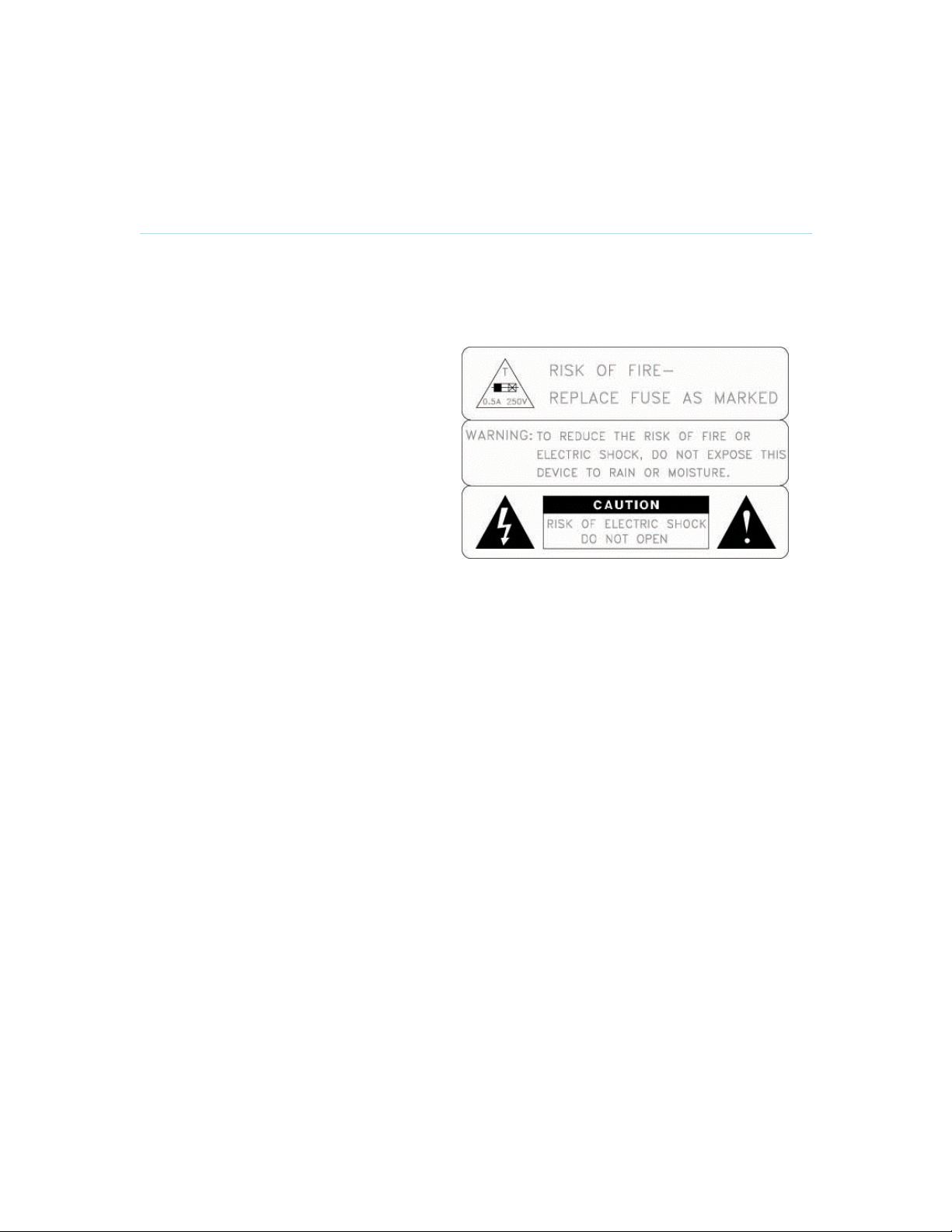
Equipment Markings
The lightning flash symbol within an
equilateral triangle is intended to alert the
user to the presence of uninsulated
“dangerous voltages” within the product’s
enclosure that may be of sufficient
magnitude to constitute a risk of electrical
shock.
The exclamation mark within an equilateral
triangle is intended to alert the user to the
presence of important operating and
maintenance (servicing) instructions within
literature accompanying the equipment.
Warnings
Water and moisture - Do not operate the equipment under or near water - for example
near a bathtub, kitchen sink, or laundry tub, in a wet basement, or near a swimming pool
or in areas with high humidity.
Cleaning - Unplug the apparatus from the wall outlet before cleaning or polishing. Do not
use liquid cleaners or aerosol cleaners. Use a lint-free cloth lightly moistened with water
for cleaning the exterior of the apparatus.
Ventilation - Do not block any of the ventilation openings of the apparatus. Install in
accordance with the installation instructions. Never cover the slots and openings with a
cloth or other material. Never install the apparatus near heat sources such as radiators,
heat registers, stoves, or other apparatus (including amplifiers) that produce heat.
Grounding or Polarization - Do not defeat the safety purpose of the polarized or
grounding-type plug. A polarized plug has two blades with one wider than the other. A
grounding type plug has two blades and a third grounding prong. The wide blade or third
prong is provided for your safety. If the provided plug does not fit into your outlet, consult
an electrician.
Power-Cord Protection - Route the power cord so as to avoid it being walked on or
pinched by items placed upon or against it, paying particular attention to the plugs,
receptacles, and the point where the cord exits from the apparatus.
Attachments - Only use attachments as recommended by the manufacturer.
Accessories - Use only with a cart, stand, tripod, bracket, or table specified by the
manufacturer, or sold with the apparatus. When a cart is used, use caution when moving
the cart/apparatus combination to avoid injury from tip-over.
Lightning - Unplug this apparatus during lightning storms or when unused for long periods
of time.
5

D1335403_T7000_MXP_User_Manual
ISDN cables - CAUTION - To reduce the risk of fire, use only No. 26 AWG or larger
telecommunication line cord.
Servicing - Do not attempt to service the apparatus yourself as opening or removing
covers may expose you to dangerous voltages or other hazards, and will void the
warranty. Refer all servicing to qualified service personnel.
Damaged Equipment - Unplug the apparatus from the outlet and refer servicing to
qualified personnel under the following conditions:
When the power cord or plug is damaged or frayed
If liquid has been spilled or objects have fallen into the apparatus
If the apparatus has been exposed to rain or moisture
If the apparatus has been subjected to excessive shock by being dropped, or the
cabinet has been damaged
If the apparatus fails to operate in accordance with the operating instructions
6

User Manual
Table of Contents
1 Introduction................................................................................................................................. 11
1.1 At a Glance .......................................................................................................................... 14
1.2 Menu Structure .................................................................................................................... 18
2 Installation................................................................................................................................... 20
2.1 Unpacking and Mounting ..................................................................................................... 21
2.2 Connecting Cables............................................................................................................... 24
2.3 Monitor Configuration........................................................................................................... 25
2.4 System Configuration........................................................................................................... 26
3 General Use................................................................................................................................ 29
3.1 The Welcome Screen .......................................................................................................... 30
3.2 Using the Remote Control.................................................................................................... 31
3.2.1 Navigation ..................................................................................................................... 33
3.2.2 Selfview......................................................................................................................... 34
3.2.3 Layout............................................................................................................................ 35
3.2.4 Mic Off........................................................................................................................... 37
3.2.5 Volume + and -.............................................................................................................. 38
3.2.6 Number and Letter keys................................................................................................39
3.2.7 Touch Tones ................................................................................................................. 40
3.3 On-screen Indicators............................................................................................................ 41
3.4 Using the Menu.................................................................................................................... 42
3.5 Make a Call..........................................................................................................................44
3.5.1 Place Video Call............................................................................................................ 45
3.5.2 Place Telephone Call .................................................................................................... 46
3.5.3 Add Call......................................................................................................................... 47
3.5.4 Call Settings .................................................................................................................. 49
3.6 Answer an Incoming Call ..................................................................................................... 50
3.7 End Call................................................................................................................................ 51
3.8 Standby................................................................................................................................ 53
3.8.1 Delay Standby for 1 hour............................................................................................... 54
3.8.2 Delay Standby for 3 hours............................................................................................. 55
3.8.3 Do Not Disturb............................................................................................................... 56
3.9 Phone Book.......................................................................................................................... 57
3.9.1 Local Phone Book ......................................................................................................... 58
3.9.2 Global Phone Book ....................................................................................................... 60
3.9.3 New Contact.................................................................................................................. 61
3.9.4 New MultiSite Contact...................................................................................................62
3.9.5 Edit Contact................................................................................................................... 64
3.9.6 Delete Contact............................................................................................................... 65
3.9.7 Copy Contact to Local Phone Book .............................................................................. 66
3.9.8 Search Global Phone Book........................................................................................... 67
3.9.9 Clear Search ................................................................................................................. 68
3.10 Camera Control.................................................................................................................. 69
3.10.1 Arrow Keys.................................................................................................................. 70
3.10.2 Zoom ........................................................................................................................... 71
3.10.3 Move Camera.............................................................................................................. 72
3.10.4 Camera Presets .......................................................................................................... 74
3.10.5 TANDBERG Tracker ................................................................................................... 75
3.11 Presentation....................................................................................................................... 76
3.11.1 Presentation Key......................................................................................................... 77
3.11.2 Presentation Menu ...................................................................................................... 78
3.11.3 PC Presenter (DVI/XGA Input).................................................................................... 80
7

D1335403_T7000_MXP_User_Manual
3.11.4 PC Soft Presenter and VNC........................................................................................ 81
3.11.5 Dual Stream (DuoVideoTF/H.239).............................................................................. 82
3.11.6 Take New Snapshot.................................................................................................... 83
3.11.7 Display Snapshot ........................................................................................................ 84
3.12 MultiSite Services .............................................................................................................. 85
3.12.1 Request Floor and Release Floor............................................................................... 87
3.12.2 MultiSite Layout........................................................................................................... 88
3.12.3 Terminal Names..........................................................................................................89
3.12.4 Chair Control ............................................................................................................... 90
3.12.5 Assign Floor and Release Floor from Participant ....................................................... 91
3.12.6 View Site and End View .............................................................................................. 92
3.12.7 Disconnect Participant ................................................................................................ 93
3.12.8 Terminate Meeting ...................................................................................................... 94
3.12.9 More about MultiSite (embedded MCU)...................................................................... 95
3.13 Control Panel ..................................................................................................................... 97
3.13.1 User Guide .................................................................................................................. 98
3.13.2 Streaming.................................................................................................................... 99
3.13.3 Far End Control.........................................................................................................101
3.13.4 Camera Preset .......................................................................................................... 102
3.13.5 Camera Tracking....................................................................................................... 103
3.13.6 Text Chat................................................................................................................... 104
3.13.7 System Information ................................................................................................... 105
3.13.8 Administrator Settings ............................................................................................... 106
3.13.9 Restart....................................................................................................................... 107
4 Administrator Settings .............................................................................................................. 108
4.1 General Settings ................................................................................................................ 109
4.1.1 Language .................................................................................................................... 110
4.1.2 System Name.............................................................................................................. 111
4.1.3 Dual Monitor................................................................................................................112
4.1.4 Auto Answer................................................................................................................113
4.1.5 Max Call Length .......................................................................................................... 114
4.1.6 Global Phone Book Settings ....................................................................................... 115
4.1.7 Permissions................................................................................................................. 116
4.1.8 Screen Settings...........................................................................................................118
4.1.9 Software Options......................................................................................................... 122
4.2 Menu Settings....................................................................................................................123
4.2.1 Menu Timeout In Call .................................................................................................. 124
4.2.2 Welcome Menu ........................................................................................................... 125
4.2.3 Welcome Picture ......................................................................................................... 126
4.2.4 Logo............................................................................................................................. 127
4.2.5 Menu on TV................................................................................................................. 128
4.2.6 Menu on PC ................................................................................................................ 129
4.2.7 Balloon Help................................................................................................................130
4.2.8 Display Welcome Text................................................................................................. 131
4.2.9 Welcome Text ............................................................................................................. 132
4.2.10 Administrator Password ............................................................................................ 133
4.3 Presentation Settings......................................................................................................... 134
4.3.1 Presentation Start........................................................................................................ 135
4.3.2 H.239........................................................................................................................... 136
4.3.3 Startup Video Source .................................................................................................. 137
4.3.4 Presentation Source.................................................................................................... 138
4.3.5 Snapshot Source......................................................................................................... 139
4.3.6 Auto-Display Snapshot................................................................................................ 140
4.3.7 PIP Appearance .......................................................................................................... 141
4.3.8 PIP Placing.................................................................................................................. 142
4.3.9 VNC Settings............................................................................................................... 143
8

User Manual
4.4 Call Quality......................................................................................................................... 144
4.4.1 Video Algorithm...........................................................................................................145
4.4.2 Audio Algorithm...........................................................................................................146
4.4.3 AAC-LD 128kbps (stereo audio) ................................................................................. 147
4.4.4 Natural Video............................................................................................................... 148
4.4.5 Video Quality...............................................................................................................149
4.4.6 Default Call Settings.................................................................................................... 151
4.5 Audio.................................................................................................................................. 154
4.5.1 Inputs........................................................................................................................... 155
4.5.2 Outputs........................................................................................................................ 157
4.5.3 Echo Control................................................................................................................ 158
4.5.4 Stereo Settings............................................................................................................ 159
4.5.5 Audio Levelling (AGC)................................................................................................. 160
4.5.6 Alert Tones and Volume.............................................................................................. 161
4.6 Video.................................................................................................................................. 162
4.6.1 Camera Tracking Mode............................................................................................... 163
4.6.2 MCU Status Line ......................................................................................................... 164
4.6.3 Floor to Full Screen.....................................................................................................165
4.6.4 Web Snapshots...........................................................................................................166
4.6.5 MultiSite Picture Mode ................................................................................................ 167
4.6.6 Picture Control............................................................................................................. 169
4.6.7 Video Name................................................................................................................. 170
4.7 Security..............................................................................................................................171
4.7.1 Encryption ................................................................................................................... 172
4.7.2 Encryption Mode ......................................................................................................... 173
4.7.3 Passwords................................................................................................................... 174
4.8 Network.............................................................................................................................. 175
4.8.1 ISDN/External/Leased E1/T1...................................................................................... 176
4.8.2 ISDN-BRI Settings....................................................................................................... 177
4.8.3 ISDN-PRI Settings....................................................................................................... 179
4.8.4 Leased E1/T1 Settings................................................................................................182
4.8.5 External Network Settings...........................................................................................183
4.8.6 LAN Settings ............................................................................................................... 185
4.8.7 H.331 Settings............................................................................................................. 195
4.8.8 Network Profiles .......................................................................................................... 196
4.8.9 Data Port ..................................................................................................................... 197
4.9 Diagnostics......................................................................................................................... 198
4.9.1 System Information ..................................................................................................... 199
4.9.2 Call Status...................................................................................................................200
4.9.3 Channel Status............................................................................................................ 201
4.9.4 System Selftest ........................................................................................................... 203
4.9.5 View Administrator Settings ........................................................................................ 204
4.9.6 Restore Default Settings ............................................................................................. 208
4.9.7 IP Address Conflict Check .......................................................................................... 209
5 Peripheral Equipment...............................................................................................................210
5.1 Interfaces ........................................................................................................................... 211
5.1.1 Video ........................................................................................................................... 211
5.1.2 Audio ........................................................................................................................... 213
5.1.3 Network ....................................................................................................................... 214
5.1.4 Data port...................................................................................................................... 219
5.2 Document Camera............................................................................................................. 220
5.3 Video Cassette Recorder (VCR)........................................................................................ 221
5.4 Additional Cameras............................................................................................................ 222
5.5 Additional Microphones...................................................................................................... 223
5.6 Telephone Add-On............................................................................................................. 225
5.7 Stereo Speaker Kit............................................................................................................. 226
9

D1335403_T7000_MXP_User_Manual
5.8 Web Interface..................................................................................................................... 227
5.9 Dual Monitor....................................................................................................................... 228
5.10 XGA Monitors and Projectors .......................................................................................... 229
5.11 VESA Display Power Management................................................................................. 230
5.12 Extended Display Identification Data (EDID)...................................................................231
6 Appendices............................................................................................................................... 233
7 Index......................................................................................................................................... 259
8 Glossary.................................................................................................................................... 261
10

No missing features when traversing the firewall
–
works with H.264,
1 Introduction
The TANDBERG 7000 MXP provides high-end performance features, large monitors and
precision audio. This creates a collaborative meeting environment for medium to large-sized
meeting rooms.
Audio Quality
High-performance audio provides a richer, more complete visual communication experience. The
MPEG4 AAC-LD standard is used to provide true standards-based CD-quality audio.
The Digital Natural Audio ModuleTM (DNAM), specifically designed for videoconferencing, provides
higher fidelity sound for a natural sound image, featuring 250W of power.
Users can record and send stereo audio from presentation and playback sources using PCs,
DVDs and VCRs.
Video Quality
Features which ensure high quality video includes:
Natural VideoTF which provides 60 fields per second true interlaced picture.
Support for H.264 in MultiSite, DuoVideo/H.239 and encryption.
SXGA input and 2 x XGA output through DVI-I (analog or digital).
WAVE II (Wide Angle View) Camera that delivers the widest angle of view in the industry.
NEW H.264 video compression up to 2Mbps.
NEW Support native 16:9 Wide XGA monitors by increasing the resolution to
1280x768 (WXGA).
NEW Automatic use of WXGA format when ”VGA Monitor Format” is set to Wide.
Network
The system supports videoconferencing via both IP and ISDN networks. The bandwidth
capabilities are:
up to 4Mbps* on IP
up to 2Mbps* on ISDN
up to 6Mbps* IP in MultiSite.
If channels are dropped during a videoconferencing session DownspeedingTF automatically
maintains connections without interruption.
NEW SIP support, both for point-to-point and MultiSite*.
Security
Secure ConferenceTF provides embedded encryption for both Point-to-Point and MultiSite call and
ensures both privacy and security.
NEW Integrated Expressway™ firewall traversal technology. When used together with
a TANDBERG Border Controller it enables:
Secure and seamless traversal of ANY firewall.
11

D1335403_T7000_MXP_User_Manual
MPEG4 audio, encryption.
Outside systems, such as home offices, to be part of the enterprise dial
plan.
Dialing to systems by URI, e.g. user@company.com.
MultiSite*
The embedded MultiSiteTF functionality can cater for up to 6 video sites and 5 audio sites and
supports screen layouts such as VoiceSwitched, AutoSplit, 4 Split and 5+1 Split. TFThe MultiSite
functionality supports any combination of ISDN and IP participants in a conference.
A superior quality and reliability is ensured by:
Supporting DuoVideo/H.239, encryption and H.264.
Rate matchingTF and TranscodingTF which supports different call rates for all sites in a
MultiSite.
The TANDBERG videoconferencing system can also be used purely as an audio-bridge (with an
ISDN connection).
Presentations
The Natural Presenter Package* (NPP) makes it possible to run presentations and comprises:
Digital ClarityTF which provides presentations of exceptionally high quality resolution video.
Duo VideoTF/H.239 which allows participants at the far end to simultaneously watch a
presenter on one screen and a live presentation on the adjoining screen.
PC PresenterTF which is an easily accessible PC connection over a wired VGA cable that
supports up to SXGA resolution.
PC SoftPresenterTF which shows PC images via the LAN connection supporting XGA
resolution.
Users can display video and presentations in the best layout based on the situation. Supported
screen layouts are:
Picture in Picture
Picture outside Picture
Side by Side
NEW PC zoom:
The PC image is transferred in native resolution and may be controlled
as a camera with zoom and pan/tilt to get SXGA resolution.
User interfaces
A web-interface is provided to handle:
Text chat/closed captioning
System management, diagnostics and software uploads
Streaming – which allows broadcasting of audio/video via an IP network
The On-Screen Menu:
Easy interface for first-time users with symbols and descriptions
Builds upon the familiar current interface
NEW True Localization with enhanced language support and international
customization:
Enabling Asian and non-Latin character text input on Web and API for
local language in Phone Book and System Names
The remote control has a simplified look and feel, auto system wake-up and large, easy-to-read
keys.
12

Introduction
Interoperability
The TANDBERG 7000 MXP is worldwide compatible with other standards-based
videoconferencing systems.
* - optional feature. To check which options are installed, select Control Panel - System Information in the menu.
TF
- TANDBERG First
13
D1335403_T7000_MXP_User_Manual
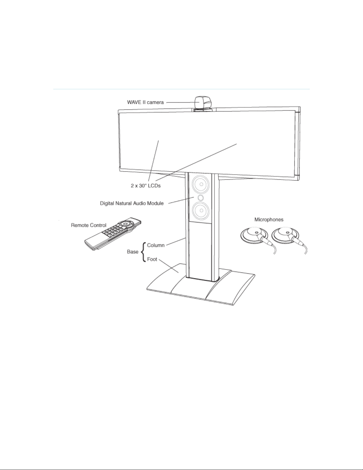
1.1 At a Glance
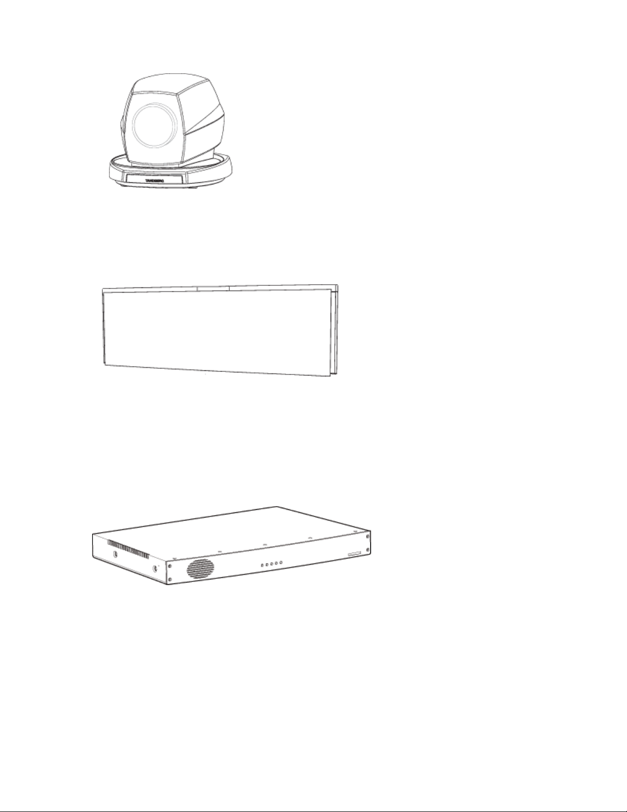
WAVE II Camera
The Main Camera is mounted on top of the product. The Main Camera includes a high quality
color camera with a fast pan/tilt/zoom action. The Main Camera is controlled by the system’s
infrared remote control and operates pan/tilt, focus and zoom. You can pre-store up to fifteen
camera positions using Camera Presets.
14
Introduction
Monitors
The main monitor displays the far-end and near-end videoconferencing sites in addition to the
menus and video from connected video sources. The second monitor displays selfview,
Snapshots and Duo Video.
Codec
The Codec is the heart of the system. The main task for the Codec is the compression of
outgoing video, audio and data, the transmission of this information to the far end and the
decompression of the incoming information - the name Codec comes from a combination of the
two words compression and decompression.
Remote Control
The remote control is used to control all functions of the system. If the screen saver is activated
(black monitor), touching the remote control will automatically wake up the system. The remote
control uses 4 AAA batteries. The system will tell you when batteries are running low. Change the
batteries at the back of the remote control.
The reach of the remote control signal is 20 meters. For users sitting in an open plan office, this
can cause problems. Use the little, white switch placed under the batteries to change the reach of
15
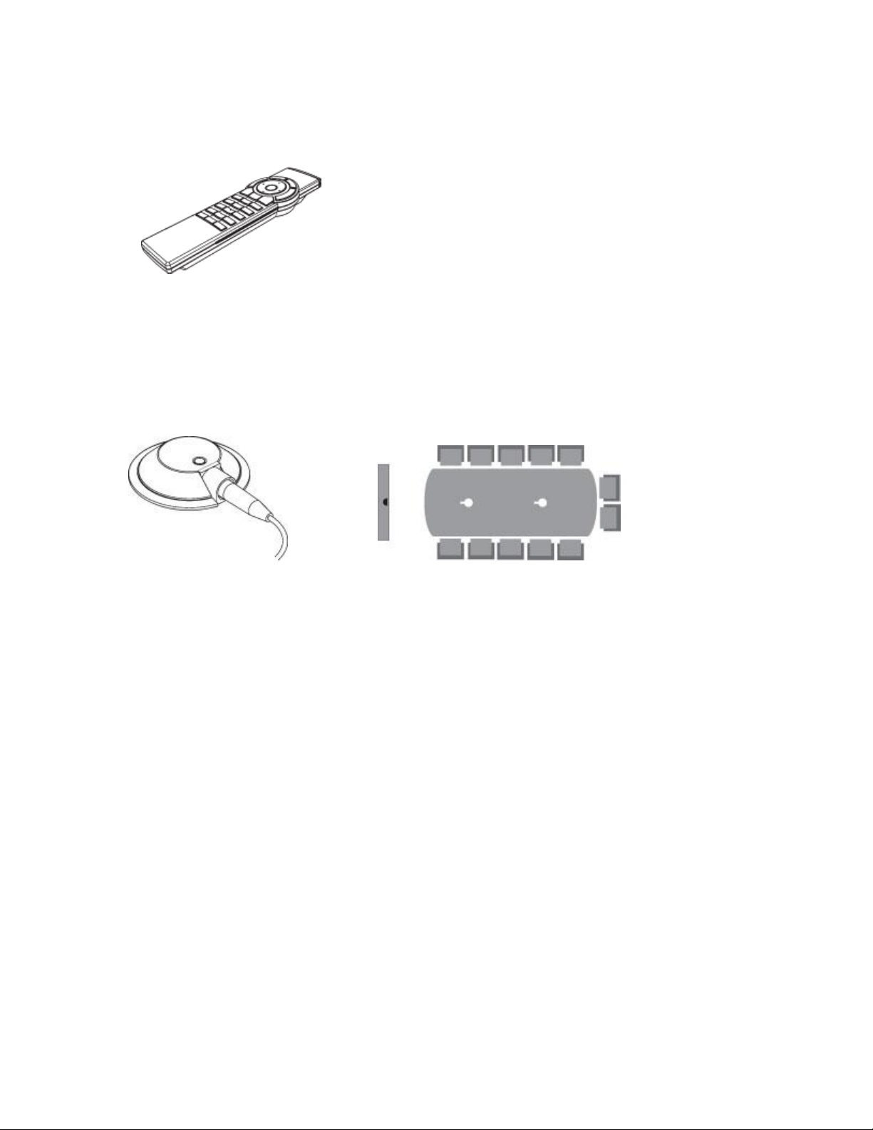
D1335403_T7000_MXP_User_Manual
the signal from 20 meters to 2 meters. This will prevent you from unintentionally controlling your
neighbor's video system, when you control your own system.
Table microphone
The high quality table microphone is designed to use on a table during a videoconference. You
can connect up to three microphones. The ideal location for the microphone is on a flat surface at
least 2m (6.5 ft) from the front of the system. The microphone cable should always point towards
the system. The system will automatically equalize sound levels. Loud and soft voices are picked
up and transmitted to the far end at approximately the same level.
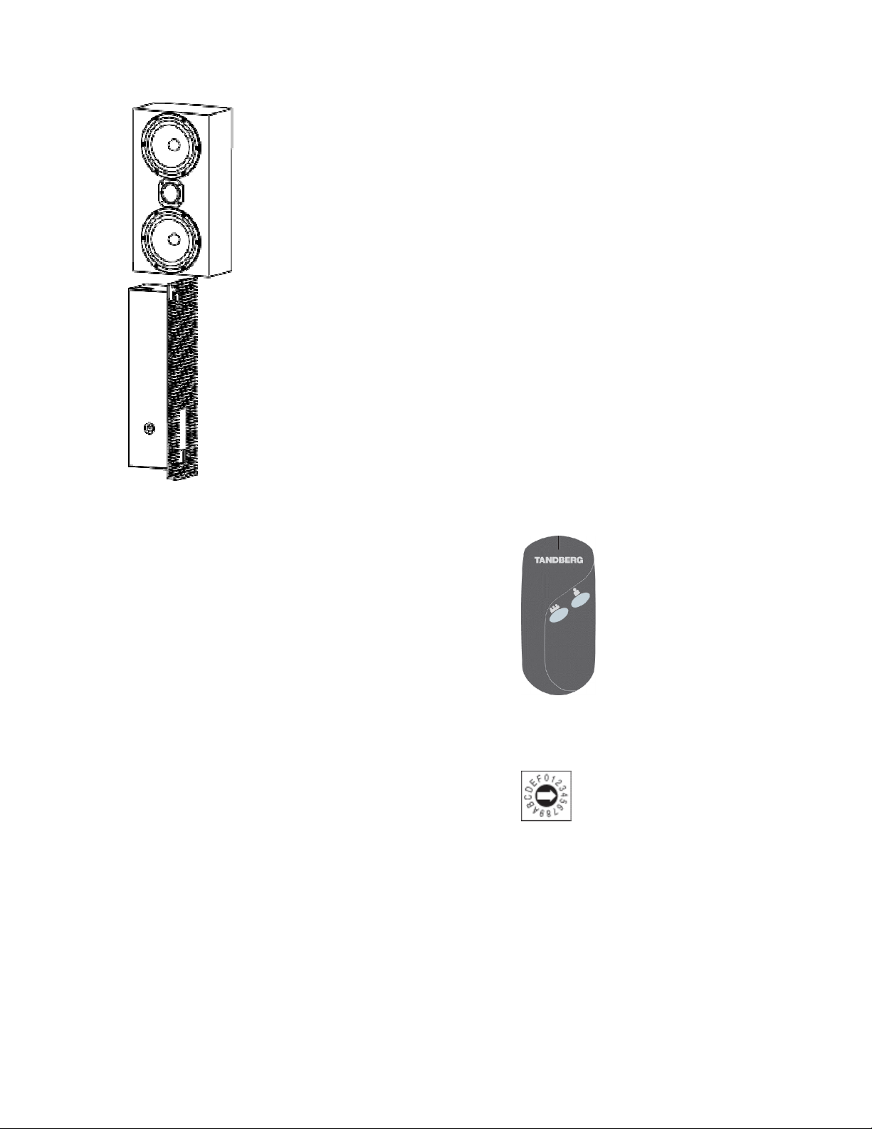
Digital Natural Audio Module
The Digital Natural Audio Module (DNAM) is designed to enhance audio quality during a
videoconference. The DNAM provides natural sounding audio - as if the person, or another sound
source, in conference is present in the same room as you.
The DNAM is a frequency-compensated sound system optimized for voice and other sounds that
appears in modern videoconferencing. It is designed and dedicated specifically for
videoconferencing requirements. Use of the highest quality speaker elements as well as proper
amplifier- and software techniques minimizes signal distortion.
The system will automatically detect the DNAM and optimize the audio output. Once detected the
audio output will be in digital format (S/PDIF). The DNAM supports both analog and digital input.
The DNAM is mounted in the bottom of the system, below the speaker cabinet.
16
Introduction
TANDBERG Tracker
The Tracker is a small infrared remote control device
made to steer the camera to any desired location within
the room. Typically, several trackers would be used with
each system.
Each Tracker has two buttons:
One Single person button to point the camera at a
specific person/location.
One Group button to point the camera at all
participants.
Beneath the battery in the Tracker, there is a switch, which
can be set to 16 different positions between 0 and F. For
camera preset 10 to 15, the numbers A to F should be
selected.
For more information, contact your local TANDBERG
representative.
17
D1335403_T7000_MXP_User_Manual
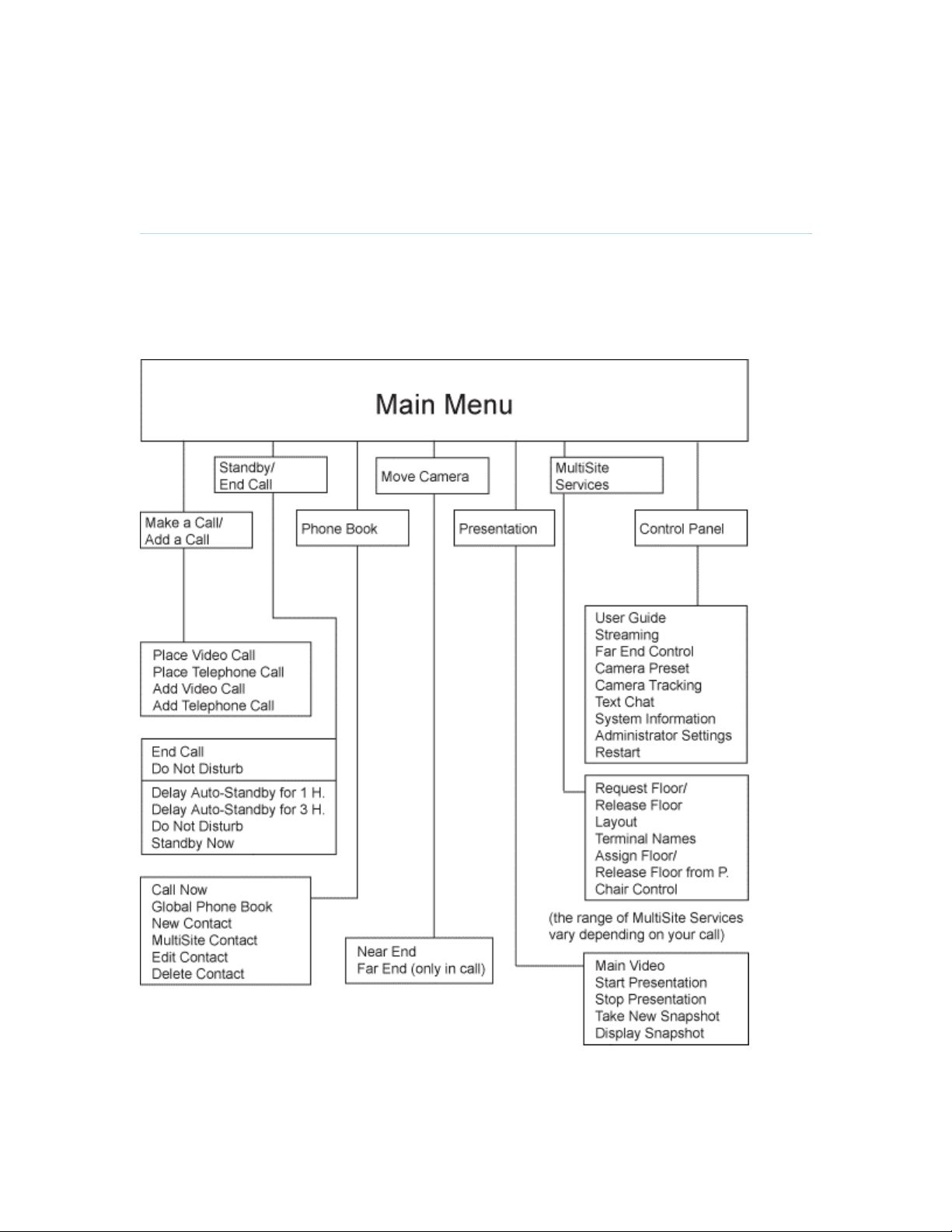
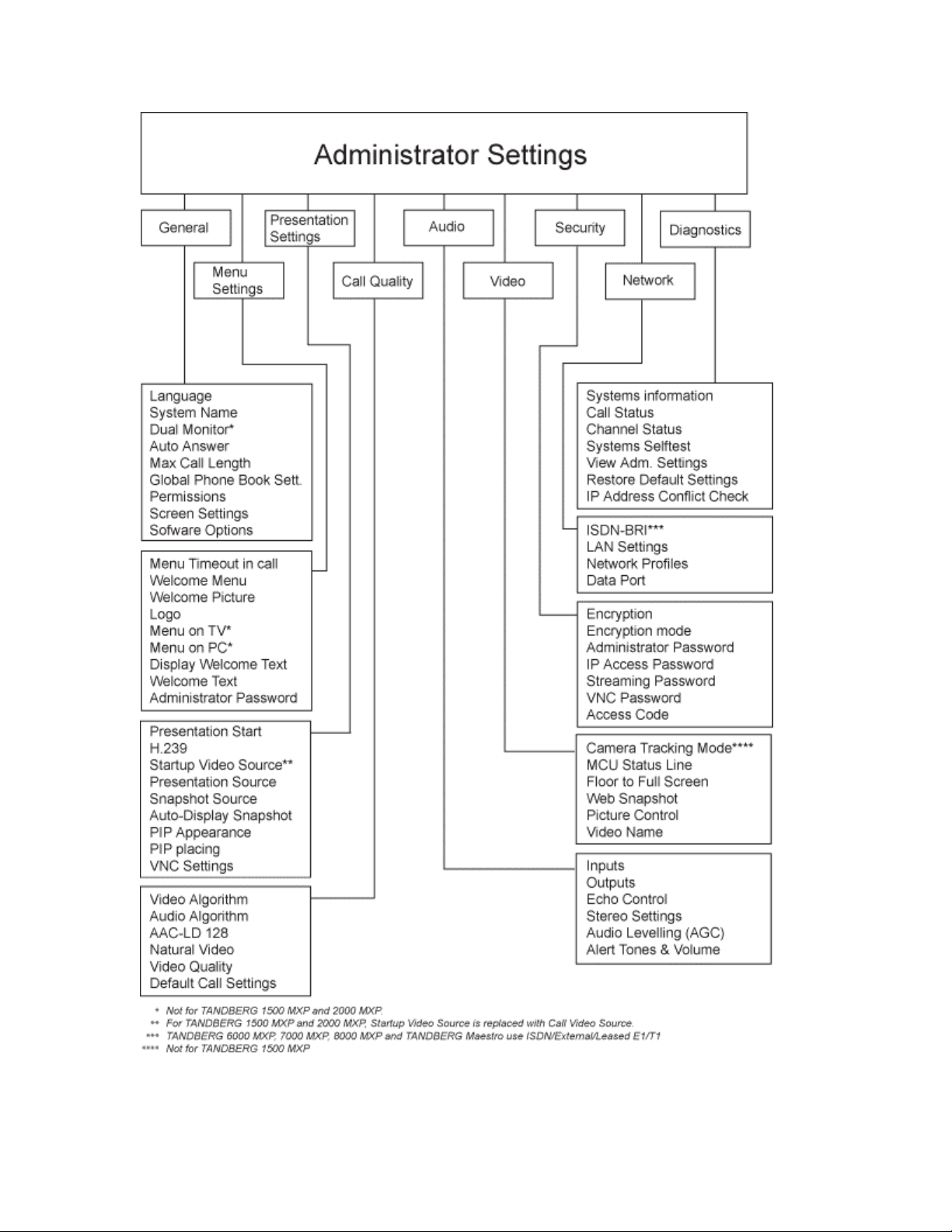
1.2 Menu Structure
The menu structure is divided in two. The Main Menu is available for all users and contains all
functionality of the system. The Administrator Menu contains all the settings of the system. Enter
Administrator Settings from Main Menu - Control Panel. Making changes to the Administrator
Settings will change the behavior of the system. The menu structure for Main Menu and
Administrator Settings is shown below.
18
Introduction
19

2 Installation
Precautions:
Never install communication wiring during a lightning storm.
Never install jacks for communication cables in wet locations unless the jack is
specifically designed for wet locations.
Never touch uninstalled communication wires or terminals unless the telephone line has
been disconnected at the network interface.
Use caution when installing or modifying communication lines.
Avoid using communication equipment (other than a cordless type) during an electrical
storm. There may be a remote risk of electrical shock from lightning.
Do not use the communication equipment to report a gas leak in the vicinity of the leak.
Always connect the product to an earthed socket outlet.
The socket outlet shall be installed near to the equipment and shall be easily accessible.
Never install cables without first switching the power OFF.
1TR6 network type is not approved for connection directly to the telecommunications
network. This network type is only to be used behind a PABX.
X.21 network type is not approved for connection directly to the telecommunications
network. This network type is only to be used together with already approved equipment,
and is not meant for direct connections to the telecommunication networks.
V.35/RS-449/RS-366 network type is not approved for connection directly to the
telecommunications network. This network type is only to be used together with already
approved equipment, and is not intended for direct connection to the telecommunication
networks.
This product complies with directives: LVD 73/23/EC, EMC 89/366/EEC, R&TTE
99/5/EEC
20
2.1 Unpacking and Mounting
Installation
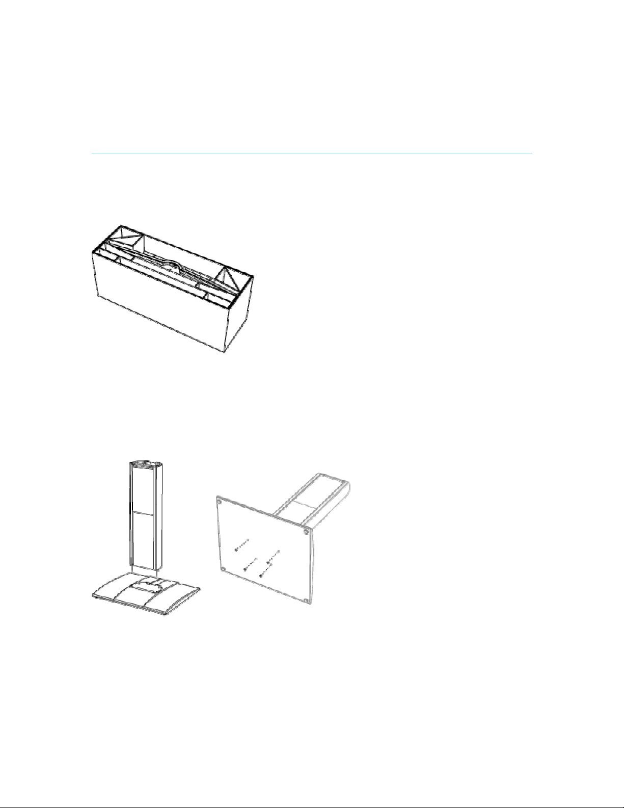
1 Unpacking
The TANDBERG 7000 MXP is delivered in one transport case with all components inside as
shown in figure 1:
Foot
Column
Monitor Frame with built-in LCD monitors
Monitor Rear Cover
W.A.V.E. II Camera
Accessories box which will contain the
following:
Two Table Microphones
Remote Control and Tracker with batteries
Cables
Figure 1
2 Mounting of the base
Place the column with the bolts into the bolt holes on the foot as shown in figure 2. Secure the
column and the foot with nuts (nuts and wrench is found in the accessories box) by tipping the
base (column/foot) as shown in figure 3. Place the base in an upright position where the system
is supposed to stand.
Documentation
Figure 2
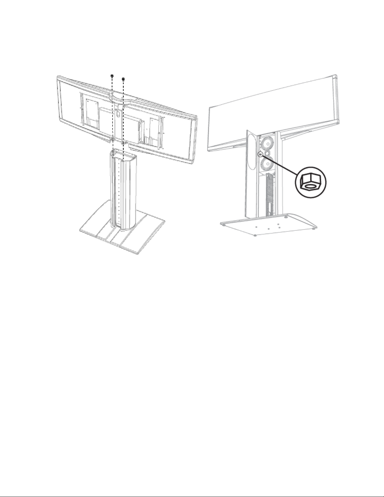
3 Installing the monitor frame
Lift the monitor frame out of the transport case. Do not remove the protective plastic film from the
monitor front before the monitor frame is securely fastened to the base.
Place the monitor frame on top of the base. Make sure that the cables from the rear side of the
monitor frame do not get stuck between the base and the monitor frame.
Figure 3
21
D1335403_T7000_MXP_User_Manual
The bolts on the bottom of the monitor frame (front) shall go through the top plate of the base.
Secure the monitor frame to the base with 2 hexagonal-shaped screws as shown in figure 4, and
with 2 nuts inside the front panel of the base as shown in figure 5.
Figure 5
Figure 4
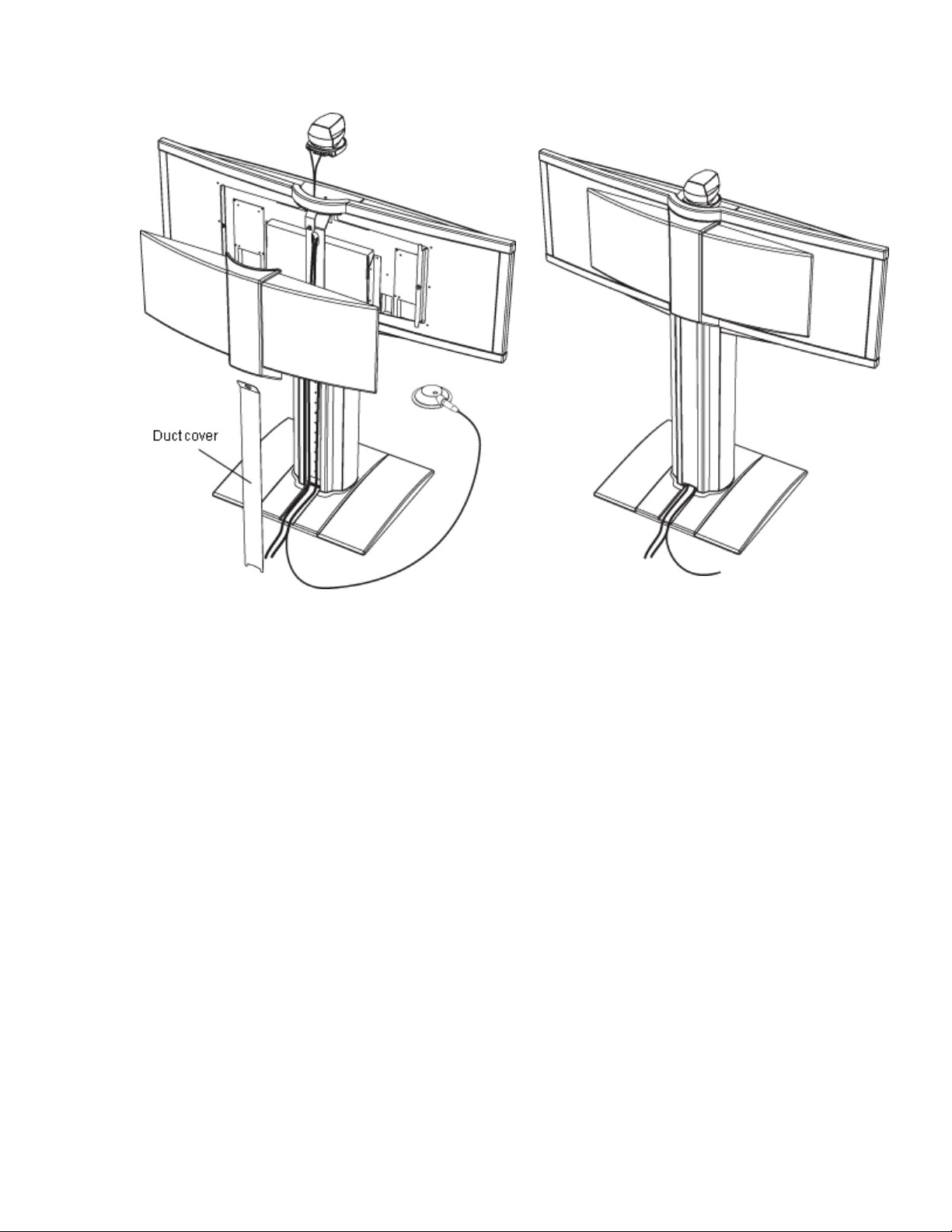
4 Monitor back cover
Make sure that all cables are connected (se chapter 2.2 Connecting cables) and then lead them
down through the cable duct on the back side of the column. Slide the duct cover of the column
into place. Make sure that all cables come out at the bottom of the column without being
squeezed by the duct cover.
The monitor back cover is kept in place by magnets. Place the cover against the magnetic points
on the monitor frame as shown in figure 7. The front cover if the monitor frame is made of plastic
and should be treated with care.
22
Installation
Figure 6
Figure 7
23

D1335403_T7000_MXP_User_Manual
2.2 Connecting Cables
1. Power cable
Connect the system power cable to the correct country variant of the power cable. Connect this
cable to an electrical distribution socket.
2. Microphone cable
Connect the microphone cables to the microphones.
3. DNAM Audio Module - audio cable
Connect the RCA cable coming out of the bottom of the base to Audio out 1 on the codec.
4. Camera cable
Place the camera centrally on top of the monitor frame, in line with the front of the screen, after
connecting the 2 cables as shown below. Remove the protection paper which is placed behind
the front glass of the camera. The camera should be aligned with the front edge of the monitor
to ensure the IR-sensor in the camera can pick up signals from the remote control.
5a. ISDN cables - using BRI interface
Connect the ISDN cables to the ISDN sockets (S/T-interface) provided by the service provider.
Your main number will be the number associated with the socket to which ISDN cable number
1 is connected. (The system does not have a built-in network terminator. If your wall socket
provides you with an ISDN U-interface, you will need an NT1 between your system and your
ISDN line, see Appendix 9.)
5b. ISDN cable - using the PRI interface
If you are using the PRI interface, the E1/T1 cable should be connected to a CSU (Channel
Service Unit). You will need a CSU between your system and the PRI line from your network
provider, see Appendix 7.
5c. Other networks - using the External Network interface
If you are using other networks, please refer to chapter 4.8.1 ISDN/External/Leased E1/T1 and
Appendix 8.
6. LAN cable
To use the system on LAN, connect a LAN cable from the Ethernet connector on the system to
your LAN.
24

2.3 Monitor Configuration
Installation
Power on
Switch the system on by connecting the power cable to an electrical distribution socket. After the
system has performed a self-test routine, the main menu will be displayed on the monitor.
25
D1335403_T7000_MXP_User_Manual
2.4 System Configuration
The system must be configured for each installation. Configuration settings can be made via the
system menu. If an external IMUX or non-standard network is being used it may be necessary to
configure any associated external equipment.
Navigate through the menu system using the arrow keys and OK. Remember to press the Save
button on the bottom of each menu to save your changes. Press Cancel (x) to return to the
previous Menu. See next section for more information about how to use the menus and the
remote control.
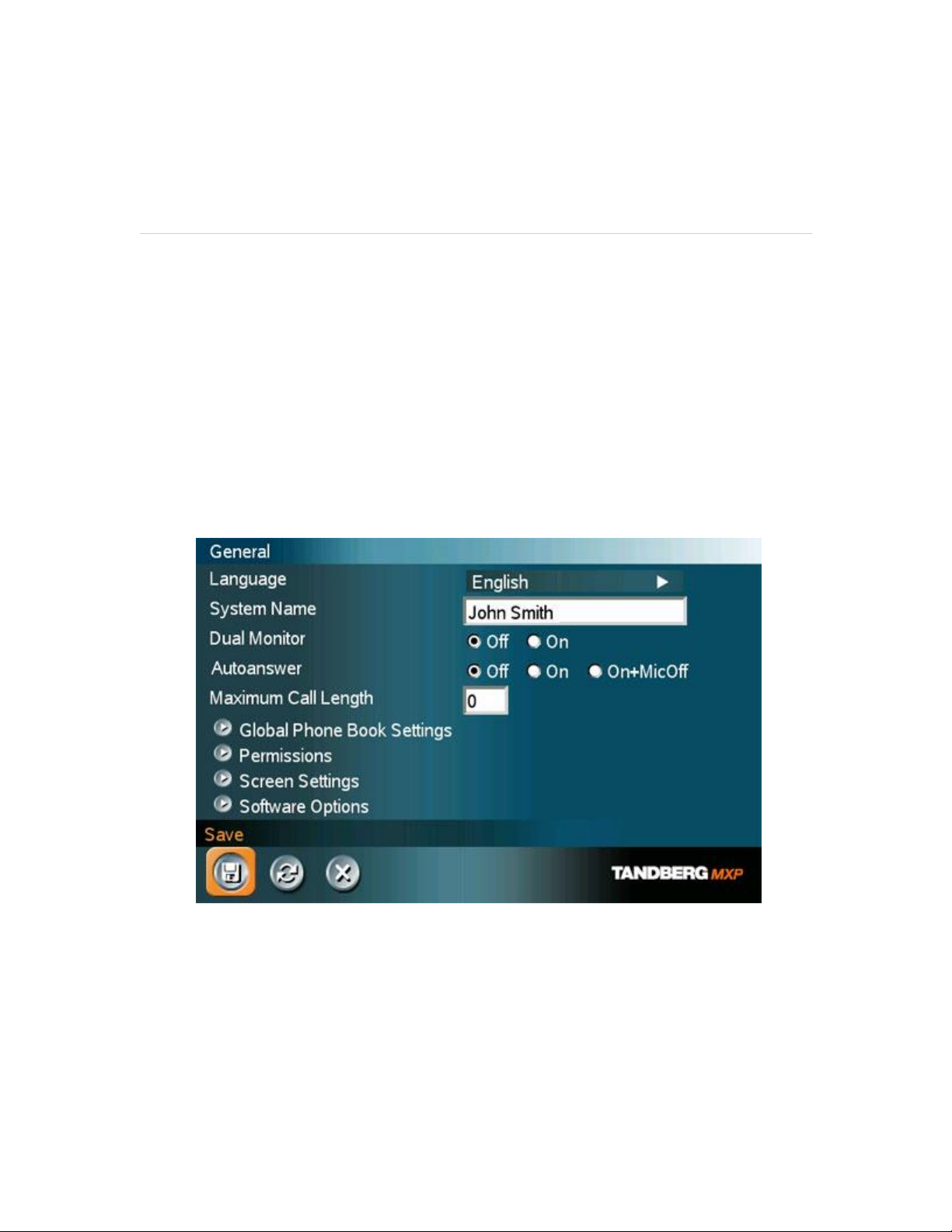
General configuration:
1. Open the General Settings menu
Press OK to open the Main Menu (if it is not already open).
Select Control Panel and then select Administrator Settings. Select General to open
the General Settings menu.
26
2. Language
Press OK in the Language field and select the language you want to use from the list.
3. System Name
Enter a name in the System Name field using the number keys on the remote control,
as you would do with a mobile or cellular phone.
4. Dual Monitor
If you are using two monitors, set Dual Monitor to "On". If you are using one monitor,
set Dual Monitor to "Off".
5. Auto Answer, Max Call Length, Global Phone Book Settings and Permissions
Leave Auto Answer, Max Call Length, Access code and Permissions unchanged if no
special needs are required. See chapter 4.1 General Settings for more information.
6. Screen Settings
When using wide screen (16:9) monitors, set TV Monitor Format to Wide (16:9).
TANDBERG also recommends setting Picture Layout to Picture outside Picture when
using 16:9 monitors. Picture outside Picture provides a display layout optimized for
wide screen monitors. The display layout may be changed at any time using the
Layout button on the remote control.
7. Software Options
To activate all options for the system, you must enter a new option key in the
Software Options menu (see paperwork accompanying your system). The MultiSite
and/or Presenter option key should be entered under “New Option Key”. Any
bandwidth option key should be entered under “New Bandwidth Key”. For more
information on these options, contact your TANDBERG representative.
8. Save changes
Remember to save any changes you make in a menu by selecting the Save button
on the Menu line and pressing OK.
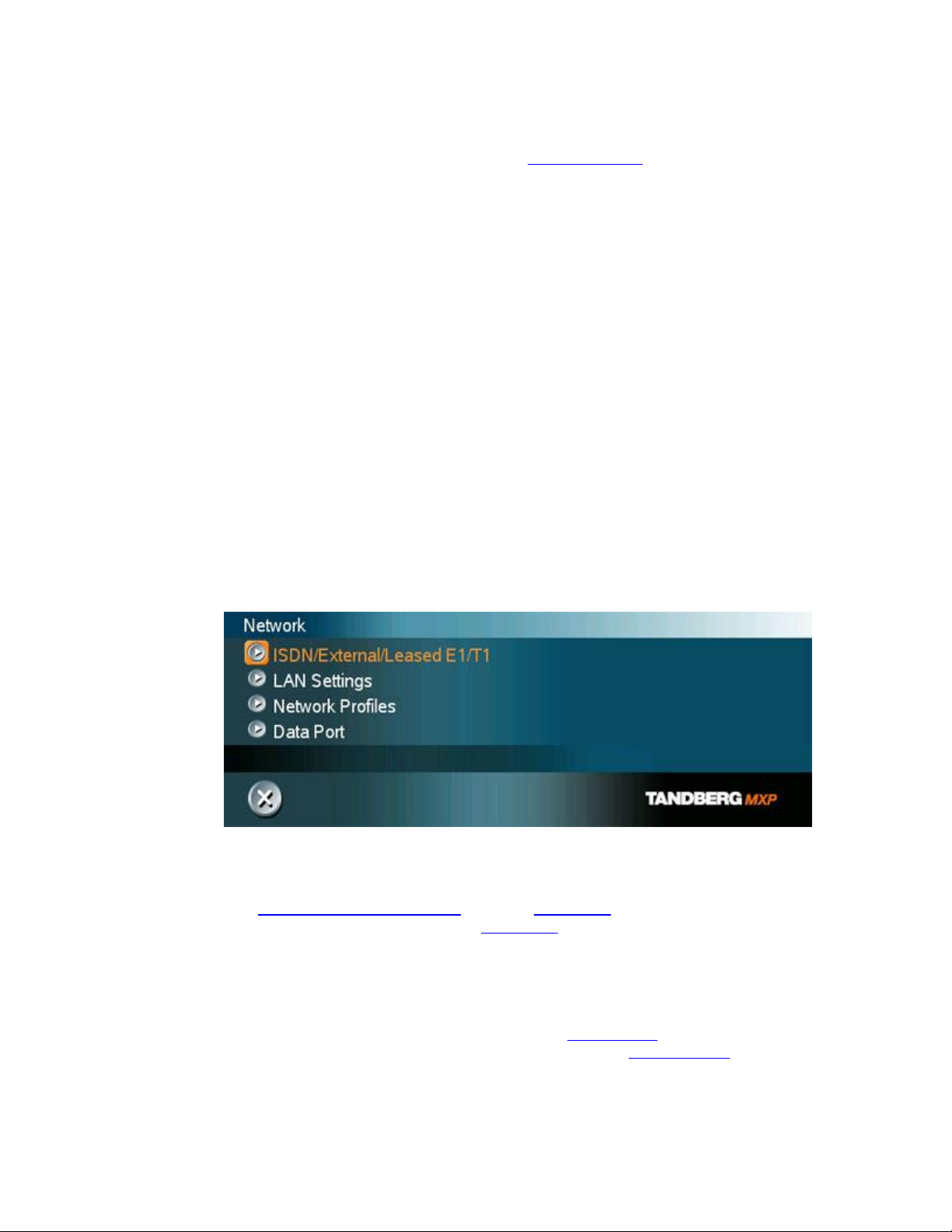
Network configuration:
1. Open the Network menu
Open the Administrator Settings menu and choose Network.
Installation
2. ISDN configuration
Set Current Network to the network you want to use. Specify the settings for the
selected network in the relevant menu. For details, follow the instructions in chapter
4.8.1 ISDN/External/Leased E1/T1. See also Appendix 9: Connecting the system to
ISDN using NT1 network adapters or Appendix 8: Connecting the system to the
Switched 56 network.
3. LAN configuration
In the Administrator Settings menu, choose Network and LAN Settings. Specify the
necessary LAN settings according to the instructions from your LAN administrator.
For details, follow the instructions in chapter 4.8.6 LAN Settings. If there is an H.323
Gatekeeper present on your LAN, see also chapter 4.8.6.2 H.323 Settings.
4. Save changes
27

D1335403_T7000_MXP_User_Manual
Remember to save any changes you make in a menu by selecting the Save button
on the Menu line and pressing OK.
28

3 General Use
Wake up the system
When the system is not in use, it is in standby mode and the screens are black. Wake up the
system by picking up the remote control. An incoming call or pressing any key on the remote will
also wake up the system.
If the system does not respond:
Make sure that the system is switched on by using the On/Off switch located at the rear
of the Codec.
Verify that your monitor is switched on. To switch the monitor on you normally push the
power button on the front of the monitor (depending on monitor type)
29
D1335403_T7000_MXP_User_Manual
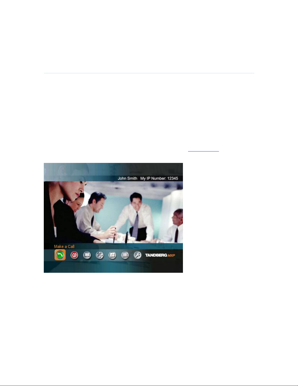
3.1 The Welcome Screen
When the system is switched on, you will see the welcome screen. The welcome screen presents
the Main Menu and displays your Main Camera image in the background (Main Camera is
system default). Your dial in numbers and system name are displayed in the upper right corner.
Your ISDN Number and IP Number are the numbers that your contacts need to place a video call
to you.
The welcome screen also provides you with the most important system information:
System Name
Your ISDN Number
Your IP Address or IP Number
It is possible to customize the text on the welcome screen. See 4.2 Menu Settings for how to edit
welcome text.
30
3.2 Using the Remote Control
General Use
The system is controlled with a remote control. Think of the remote control as a mobile phone
with number keys and call keys. Use the arrow keys and OK to navigate the menu. The system’s
most commonly used functions are also accessible directly from the remote control.
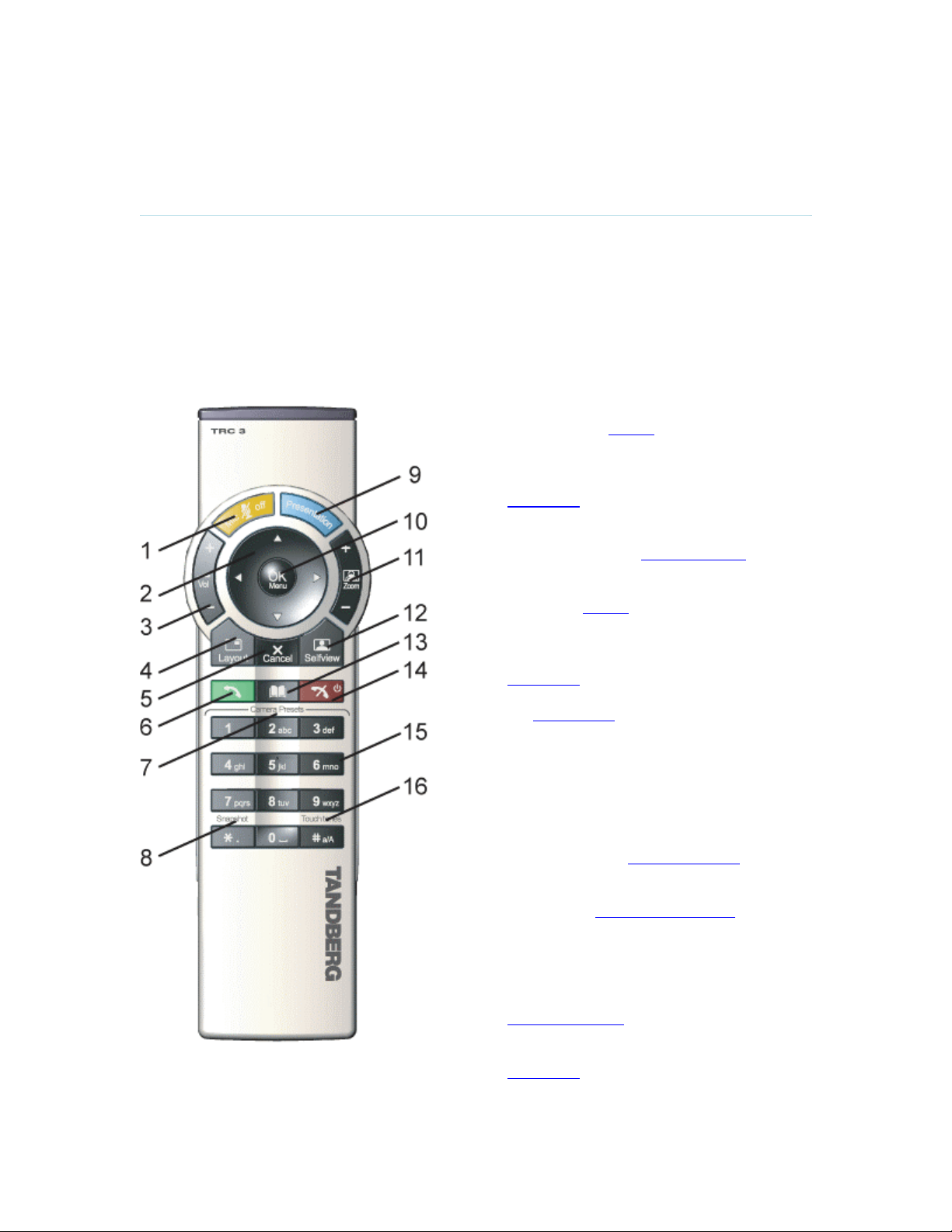
The Infra Red (IR) sensor for the remote control is located in front of the WAVE II Camera. There
is also a second IR-sensor located in the front of the Codec itself, which will be automatically
enabled if the WAVE II Camera is not connected.
1. Mic Off turns your microphone on and
off. (See 3.2.4 Mic off)
2. Arrow keys are used for navigation in
the menu and for moving the camera
when the menu is hidden. (See 3.2.1
Navigation)
3. Volume + and – adjusts the Codec
volume only and not the monitor's
volume. (See 3.2.5 Volume + and -)
4. The Layout key toggles between full
screen and different display layouts.
(See 3.2.3 Layout)
5. Cancel takes you back one step in the
menu system. Use Cancel to delete
characters in an input field. (See 3.2.1
Navigation)
6. Press the Call key to place a call. (See
3.5 Make a Call)
7. Camera presets define specific camera
positions. Move the camera to the
desired position and press and hold a
number key for 1 second to save the
current camera position to that number
key. To activate a preset whilst in a call,
simply press and release that number
key. (See 3.10.4 Camera Presets)
8. Snapshot takes a snapshot of your
video. (Only while you are in a call)
(See 3.11.6 Take New Snapshot)
9. The Presentation key switches to a
predefined presentation source. If the
Presentation key is held down for 1
second then the Presentation video
sources menu will appear. (See 3.11.1
Presentation Key)
10. Press OK/Menu to show the menu and
to select menu items. (See 3.2.1
Navigation)
31

D1335403_T7000_MXP_User_Manual
in and out. (See 3.10.2 Zoom)
12. Selfview displays your outgoing video.
Press Selfview again to turn selfview off.
(See 3.2.2 Selfview)
13. Store and recall your video contacts via
the system Phone Book for easy
placement of calls. (See 3.9 Phone
Book)
14. Use the red End Call key to end the
current call. Pressing this key when not
in a call will place the system in Standby
mode. (See 3.7 End Call and 3.8
Standby)
15. Number/Letter keys function in the same
manner as with a mobile or cellular
phone. (See 3.2.6 Number and Letter
keys)
16. Press Touch tones when you are in a
call and need to dial extension numbers
etc. (instead of presets). Press the
OK/Menu button to exit Touch Tones.
(See 3.2.7 Touch tones)
32

3.2.1 Navigation
General Use
Arrow keys and OK
Navigate in the menu with arrow keys. The orange selector on screen
shows the selected item. Press OK to select.
Cancel key
In the main menu, pressing Cancel (X) will hide the menu. If the menu is
hidden, bring it back with OK. In other menus, pressing Cancel (X) takes
you one step back. In an input field, pressing Cancel (X) will delete
characters/numbers to the left.
Back/Cancel button
The X button in the menu corresponds with the X key on the remote.
33

D1335403_T7000_MXP_User_Manual
3.2.2 Selfview
Selfview shows the outgoing image. Normally this is the image from the main camera, e.g.
showing the user of the system.
Selfview is useful for single monitor systems to be able to see the outgoing video. On dual
monitor systems you already have selfview on the dual monitor.
How to use Selfview:
1. In a call, press the Selfview button once to switch from far end video to near end video on
the main monitor to see a full screen picture of the outgoing video. Press Selfview again
to turn selfview off and go back to normal.
2. Outside a call, pressing the Selfview button will switch between the near end video and a
black screen on the main monitor.
The above behaviour is similar for both single monitor systems and dual monitor systems.
34

3.2.3 Layout
General Use
The layout of the screen can either be shown as Picture in Picture (PIP) or Picture outside Picture
(POP) when displaying more than one video image. The behaviour of the Layout button is
dependent on the Picture Layout setting in Administrator Settings - General - Screen Settings,
see 4.1.8 Screen Settings.
3.2.3.1 Picture in Picture
With set to PIP, the Layout button makes it possible to see a second image in a smaller view in
one of the corners of the screen. The second image will be placed on top of the main image. The
user can decide in which corner the second image is to be displayed.
PIP will always appear on the main monitor.
Automatic PIP is the system's default setting. That implies that PIP will automatically be shown
when suitable, see 4.3 Presentation Settings for more details.
How to use Layout with Picture in Picture:
1. Press Layout once to bring up a PIP.
2. Press Layout again to move it around in the corners of the screen and finally hide it.
3. Pressing and holding Layout for 1 second will hide the small picture directly from any
position.
Example of PIP
3.2.3.2 Picture outside Picture
When set to POP, the Layout button makes it possible to see up to three images in a composition
optimized for wide screens. The second image can be displayed either as a small image next to
the main image, or side-by-side the main image.
Press once to get an extra picture in a smaller view. Press twice to get side-by-side view. Press
again to go back to full screen view. You can also go back to full screen directly by pressing and
holding Layout for 1 second. It is recommended to use Picture outside Picture for wide screen
monitor systems.
35

D1335403_T7000_MXP_User_Manual
How to use Layout button with POP:
1. Press the Layout button to get the 1+3 layout. The far end image will be displayed as the
main video, with the near end, usually the user of the system, as a smaller image in the
upper right corner. If Duo Video / H.239 is used, the Duo Video image is displayed as the
main image and the far end and near end as smaller images to the right, see figure below
for an example.
2. Press the Layout button again to see the images side-by-side, e.g. 1+1 layout, where the
far end and near end are displayed as images of equal size, see figure below.
3. The third time the Layout button is pressed, the normal full screen view of the far end is
displayed..
4. Pressing and holding Layout for 1 second will always bring you back to full screen.
Note that if both TV monitor format and VGA format is set to Normal, the system will skip the 1+3
layout, which is not beneficial for 4:3 monitors.
Example of POP
Example of Side by Side
36

3.2.4 Mic Off
General Use
To mute your microphone during a call, press Mic off. An on-screen indicator appears when the
microphone is off. In a call, if audio is detected, the on-screen symbol will start to flash. Pressing
Mic off one more time will activate the microphone again.
Mic off will mute microphone inputs and audio 4 input, but will not mute audio from the AUX and
VCR inputs.
When an incoming call is answered, the microphone may be in the off state because the Auto
Answer setting is On+Mic off (see 4.1.4 Auto Answer). The icon will start to flash when you
start speaking. Remember to turn the microphone on before a meeting.
37

D1335403_T7000_MXP_User_Manual
3.2.5 Volume + and -
Press the Volume key to adjust the volume level of the codec only and not the monitor. An onscreen indicator will show the current level.
38

3.2.6 Number and Letter keys
General Use
Pressing a number key when you are outside a call will take you to the call menu. When you are
in a call, the number keys are used for Camera Presets. Press a number and you go to the
corresponding Camera Preset (see 3.10.4 Camera Presets). However, when you are in an input
field where numbers are required, the system automatically goes to number mode and you can
dial numbers with the number keys as usual.
When you are in an input field where letters are required, the system automatically goes to letter
mode. Writing letters works like on a mobile phone. Press the key that corresponds to your
desired letter. Press the key as many times as you need to get the right letter. Change to lower or
back to upper case letters with the a/A key, and space with the 0 _ key.
To write numbers in a text input field, press the button through all the letters. Press once more
and the number will appear.
Example: How do I write "System 123" in the System Name input field (in General in
Administrator Settings)?
Press the 7-key four times to get an "S".
Press the #-key once to switch between upper case and lower case letters.
Press the 9-key three times to get a "y".
Press the 7-key four times to get an "s".
Press the 8-key once to get a "t".
Press the 3-key twice to get an "e".
Press the 6-key once to get an "m".
Press the 0-key once to get space.
Press the 1-key three times to get a "1".
Press the 2-key four times to get a "2".
Press the 3-key four times to get a "3".
39

D1335403_T7000_MXP_User_Manual
3.2.7 Touch Tones
Sometimes you need to dial extension numbers with the number keys when you are in a call.
Pressing numbers will result in a camera preset. In these cases, press # to enable Touch tones.
An indicator will tell that Touch tones are enabled. Now you can enter your extension number with
the number keys. Finish with OK to exit Touch tone mode.
40
3.3 On-screen Indicators
General Use
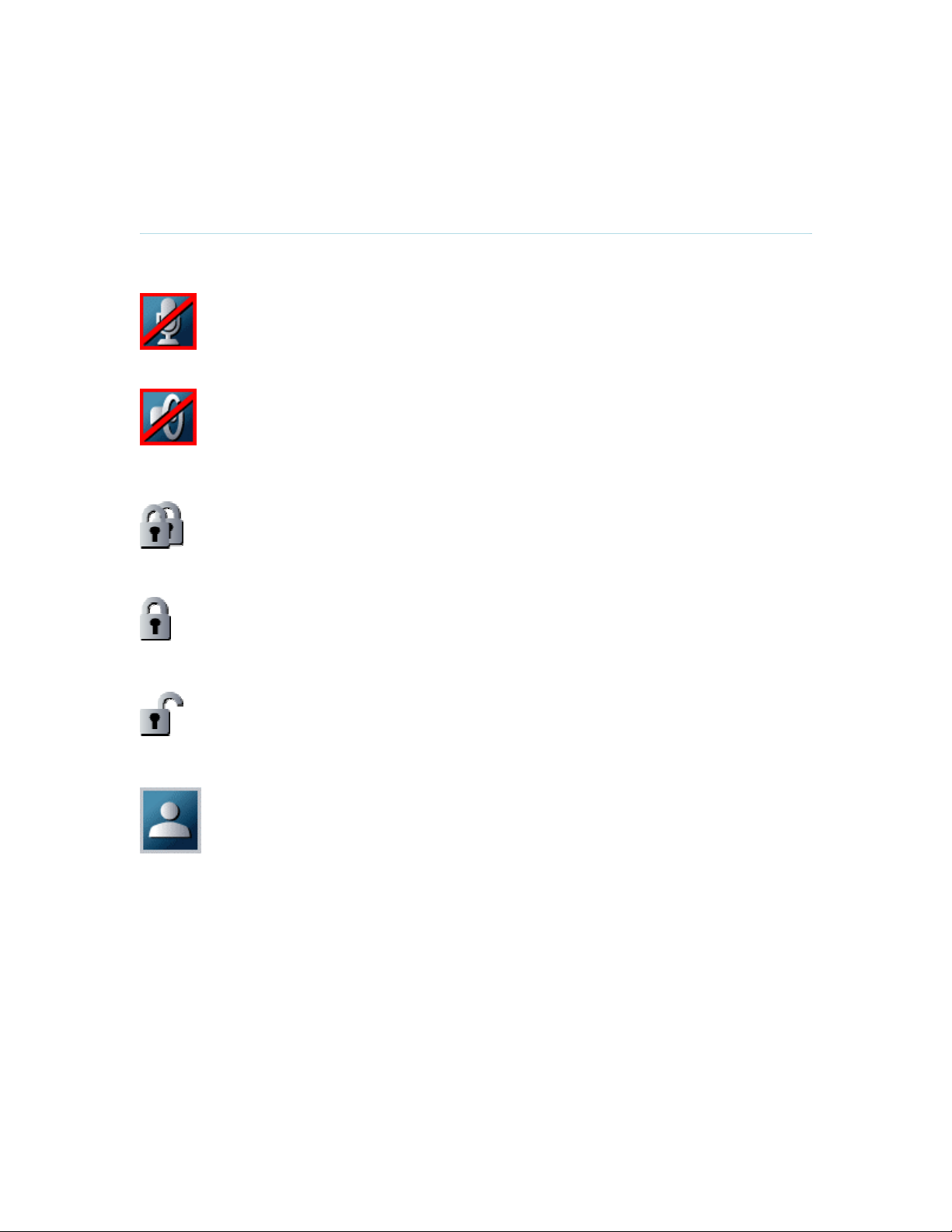
The system has a number of icons signaling different settings:
Microphone Off
This indicator is shown when the microphone is turned off. Press the Mic off
button again to turn the microphone back on.
Volume Off
This indicator is shown when the volume is turned off. Press Volume + to turn the
volume back on.
Secure Conference, AES
This double padlock indicator is shown when AES encryption (Secure
Conference) is active.
Secure Conference, DES
This padlock indicator is shown when DES encryption (Secure Conference) is
active.
Not Secure Conference
This open padlock indicator is shown during the initialization phase for encryption.
During this period the call is not secure.
Floor
This indicator is shown when you are displayed in full screen in a multipoint
conference.
41

D1335403_T7000_MXP_User_Manual
3.4 Using the Menu
Main menu outside a call and in a call.
Press the Menu button on the remote control to display the menu. The menu contains all
functions needed in order to control the system.
42

General Use
The menu contains the following items:
Make a Call/Add Another Call
Standby/End Call
Phone Book
Move Camera
Presentation
MultiSite Services
Control Panel
See 1.2 Menu Structure for a full overview of the menu.
The functions of the menu are displayed as icons. The currently selected icon is marked by an
orange square, and the name of the corresponding function is displayed on the line above, see
the figure above.
Press the OK button to activate the current selected function.
The menu automatically times out after 15 seconds if not used, see 4.2.1 Menu timeout. Press
the Menu button to bring it back. It is also possible to hide the menu manually by pressing the
Cancel button on the remote control.
43

D1335403_T7000_MXP_User_Manual
3.5 Make a Call
Display the call menu by either:
1. Select Make a Call from the menu, or
2. Press the green Call button on the remote control
The TANDBERG system can make both video calls and telephone calls. See 3.5.1 Place Video
Calls and 3.5.2 Place Telephone Calls for details.
Default Call Settings specifies the quality of the call, see 3.5.4 Call Settings for more details. It is
possible to alter the default call settings for the current call if required. The Default Call Settings
are defined in Control Panel - Administrator Settings - Call Quality - Default Call Settings, see
4.4.6 Default Call Settings for more details.
For setting up a MultiSite conference, see 3.5.3 Add Call for more details.
44

3.5.1 Place Video Call
General Use
In the Make a Call menu enter the Dial Number either:
1. Manually, or
2. Select the book symbol in order to display the Phone Book and select a conference
participant, see 3.9 Phone Book for details.
When dialing manually, toggle between ABC/abc by pressing the # button on the remote control
and between abc/123 by holding the # button for one second. Use a star as separator in IP
addresses. If a system is registered on a gatekeeper or border controller with DNS support, there
are several ways to call into the system:
<IP address>
<E.164>
<H.323 ID>
<H.323 ID>@<domain>
<E.164>@<domain>
See 4.8.6.2 H.323 Settings for details.
Place the call by either:
1. Press OK on the remote control so that the Place Video Call icon is selected, and press
OK once again, or
2. Use the arrow button on the remote control to select the Place Video Call icon and press
OK, or
3. Press the green call button on the remote control.
Note that the call will be set up as a telephone call if the Call Type in Call Settings is set to
Telephone Call. See 4.4.6 Default Call Settings for more details.
45

D1335403_T7000_MXP_User_Manual
3.5.2 Place Telephone Call
In the Make a Call menu enter the Dial Number either:
1. Manually, or
2. Select the book symbol in order to display the Phone Book and select a conference
participant, see 3.9 Phone Book for details.
When entering a Dial Number manually, toggle between abc/123 by pressing the # button on the
remote control for one second. Use a star as separator in IP addresses.
Place the call by either:
1. Press OK on the remote control, select the Place Telephone Call icon and press OK once
again, or
2. Use the arrow button on the remote control to select the Place Telephone Call icon and
press OK.
When dialing a telephone number and pressing the green Call button on the remote control, the
system will in most cases automatically interpret the number as a telephone number and not a
video number. The interpretation can sometimes take a little while and it is faster to use the Place
Telephone Call button in the menu.
Note that the call will be set up as a telephone call even if the dial number entered is a video
number, and the Call Type in Default Call Settings is set to Video Call (i.e. selecting the Place
Telephone Call icon will override these settings). See 4.4.6 Default Call Settings for more details.
46

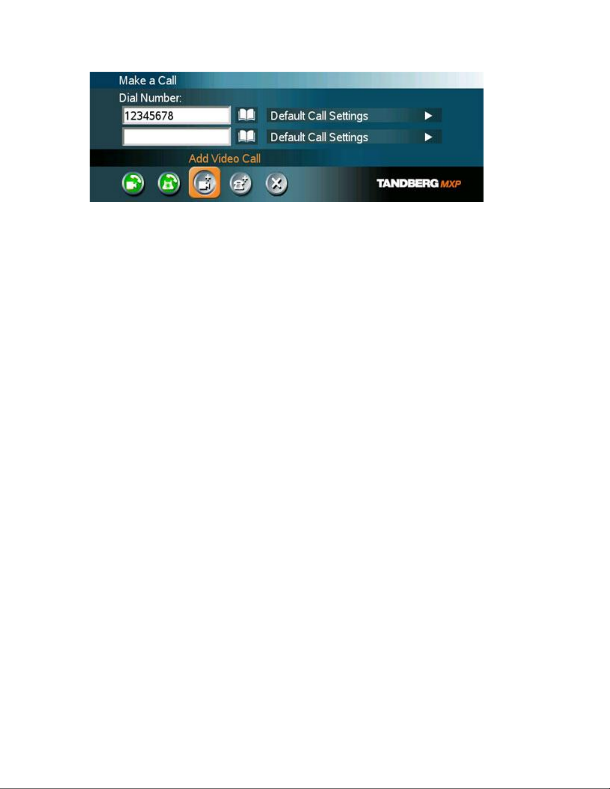
3.5.3 Add Call
General Use
(optional feature)
Conference systems with built-in MultiSite can handle up to 6 video calls and 5 telephone calls
simultaneously.
It is possible to both set up a conference with many participants and also add participants during
a conference.
Set up a conference with two or more participants
In the Make a Call menu enter the Dial Number either:
1. Manually, or
2. Select the book symbol in order to display the Phone Book and select a conference
participant, see 3.9 Phone Book for details. It is also possible to select a predefined
MultiSite entry, see 3.9.4 New MultiSite Contact.
3. Press OK on the remote control.
Add another participant to the conference by either:
1. Select the Add Video Call icon if the next participant is using a video system, and press
OK, or
2. Select the Add Telephone Call icon if the next participant is using a telephone system,
and press OK.
A new entry is now displayed in the call list. Enter the number as described above.
It is also possible to set up a list of all the wanted conference participants by selecting the Add
Video Calls and Add Telephone Calls the wanted number of times, and enter their numbers
afterwards.
Place a MultiSite call:
1. If the call is a mixed conference with both video and telephone participants, select the
Place Video Call icon, or
2. If the call is a conference with telephone participants only, select the Place Telephone
Call icon.
Add participant(s) during a conference
Display the call menu during a call by either:
1. Select Make a Call from the menu, or
2. Press the green Call button on the remote control
Enter the new participants in the same way as described above.
47
D1335403_T7000_MXP_User_Manual
48

3.5.4 Call Settings
General Use
The Call Settings specifies the quality of the call. Each call will be set up with the Default Call
Settings if the settings are not altered. In this case the field is named Default Call Settings. If the
settings for some reason are altered for the current participant in the current call, the name of the
field will be changed to reflect this.
Usually it is not necessary for the user to alter the settings.
The Default Call Settings are defined in Control Panel - Administrator Settings - Call Quality -
Default Call Settings, see 4.4.6 Default Call Settings for more details.
When setting up a call in the Make a Call menu:
1. Select the Default Call Settings field for the participant and press the OK button on the
remote control.
2. Make desired changes to Call Type, Network, Bandwidth and Restrict (56k), see 4.4.6
Default Call Settings for more details. If this is to be the new default call settings, select
Set as Default in the menu.
3. Select the OK icon and press the OK button on the remote control. The name of the Call
Settings field will reflect the changes made.
It is possible to make the changes made to the Call Settings default by selecting Set as Default
and OK. These settings will now be the default settings for all future manually dialed calls.
These settings are also available in the menu Control Panel - Administrator Settings - Call Quality
- Default Call Settings.
49
D1335403_T7000_MXP_User_Manual
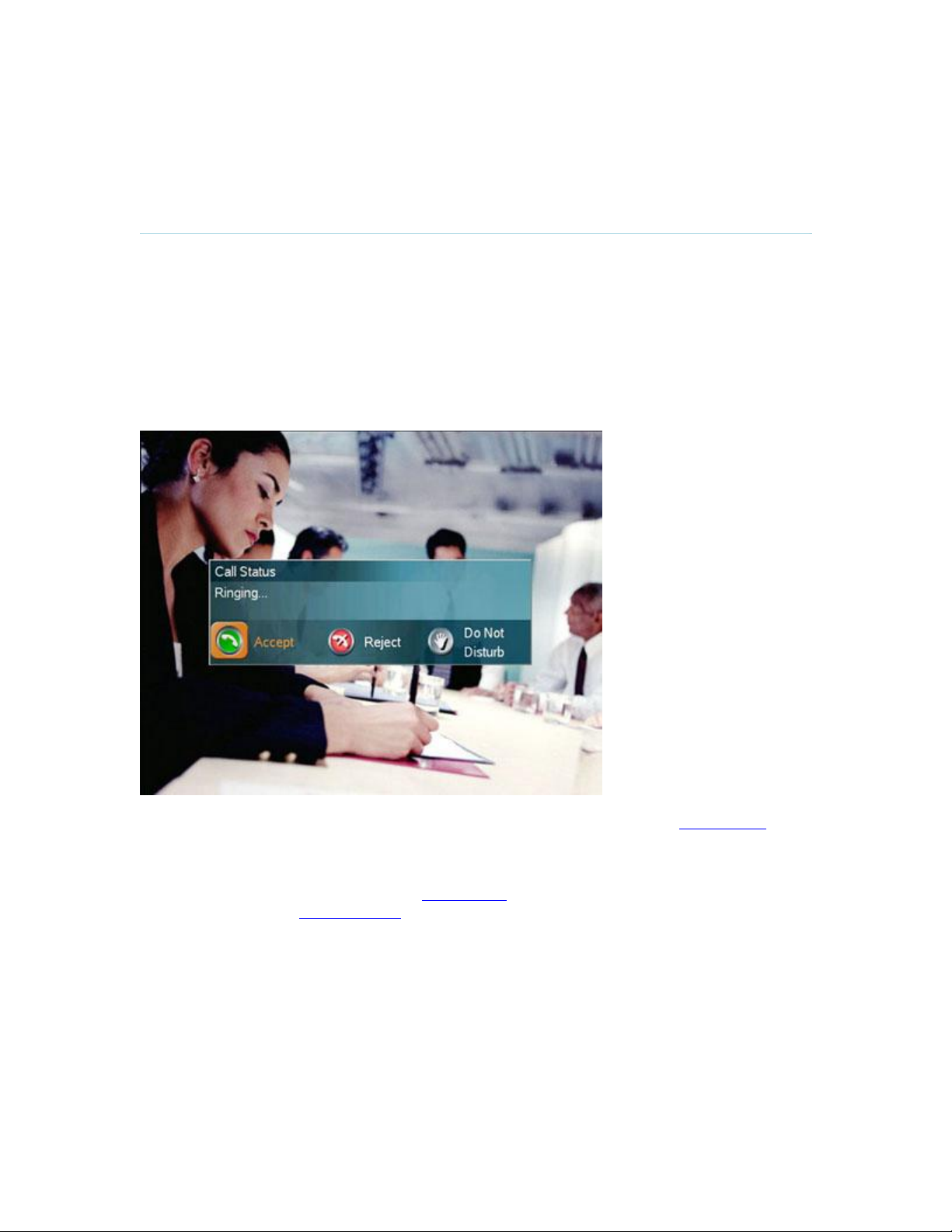
3.6 Answer an Incoming Call
How to answer an incoming call:
To accept an incoming call, press the OK button or the green Call button on the remote
control.
How to reject an incoming call:
To reject an incoming call, select the Reject icon and press the OK button, or press the
End Call button on the remote control.
Incoming calls will connect automatically if Auto Answer is set to On, see 4.1.4 Auto Answer for
details.
When idle, the system will accept all incoming calls as long as Incoming MCU Calls and Incoming
Telephone Calls are set to On, see 4.1.7 Permissions for details. Also, Do Not Disturb must not
be activated, see 3.8.3 Do Not Disturb for more details.
50

3.7 End Call
General Use
How to end a call:
Press the red End Call button on the remote control, or
Press the Menu button on the remote control to display the menu and select End Call.
When the End Call dialog box is displayed either:
Press the red End Call button on the remote control again, or
Press the OK button to confirm that the call is to be ended.
How to end a MultiSite call:
Press the red End Call button on the remote control, or
Press the Menu button on the remote control to display the menu and select End Call.
In the list of participants:
Select a participant and press the OK button or the red End Call button.
Select End All Calls to end the whole conference.
51

D1335403_T7000_MXP_User_Manual
Note that switching off the monitor(s) will not end a call.
52

3.8 Standby
General Use
The system will automatically go to Standby mode when it is not in use. In standby mode, the
screen(s) are black. It is however still possible to receive incoming calls.
How to turn on the standby mode manually:
Select Standby from the menu and select Standby Now, or
Press the End Call button on the remote control twice.
How to turn off the standby mode:
When the system is in standby, pick up the remote control, or press any of its keys to
activate the system again.
The standby mode of the system should be used if the system is to be left idle.
Note! Standby is not activated by switching off the monitors.
It is possible to postpone the system from entering standby mode for 1 hour or 3 hours, see 3.8.1
Delay Standby for 1 hour and 3.8.2 Delay Standby for 3 hours.
53

D1335403_T7000_MXP_User_Manual
3.8.1 Delay Standby for 1 hour
Delay Standby for 1 hour postpones the system from entering standby mode for 1 hour.
This function is useful when using the monitors for a local presentation to prevent the system
from automatically blanking the monitors.
It is also possible to postpone the system from entering standby mode for 3 hours, see 3.8.2
Delay Standby for 3 hours.
54

3.8.2 Delay Standby for 3 hours
General Use
Delay Standby for 3 hours postpones the automatic standby mode for 3 hours.
This function is useful when using the monitors for a local presentation to prevent the system
from automatically blanking the monitors.
It is also possible to postpone the system from entering standby mode for 1 hour, see 3.8.1 Delay
Standby for 1 hour.
55

D1335403_T7000_MXP_User_Manual
3.8.3 Do Not Disturb
To prevent the system from accepting any incoming calls, the function Do Not Disturb has to be
activated. The caller will hear a busy tone when calling the system. The monitor will be black
when Do Not Disturb is active, see figure below.
End Do Not Disturb by pressing any key on the remote control.
56

3.9 Phone Book
General Use
The Phone Book is available via the Phone Book button on the remote control, directly from the
menu, or when Make a Call is selected.
Using the Phone Book is time saving and prevents the user from inadvertently calling the wrong
number. The contacts are sorted alphabetically.
Navigate up and down in the Phone Book with the arrow keys on the remote control. Use the
letter keys to search through the contacts beginning with the typed letter.
The functions in the Phone Book are available when pressing the left arrow key on the remote
control, and then the up and down arrow keys. Note that the last selected contact will be marked.
The Phone Book is divided in Local Phone Book and Global Phone Book. The Global Phone
Book is available if the system is connected to an external management system like the
TANDBERG Management Suite (TMS).
It is possible for the user to edit the contents of the Local Phone Book but not of the Global Phone
Book. Also, the Local Phone Book contains lists of the Last Numbers Dialed, Missed Calls and
Call History.
See 3.9.1 Local Phone Book and 3.9.2 Global Phone Book for details.
57
D1335403_T7000_MXP_User_Manual
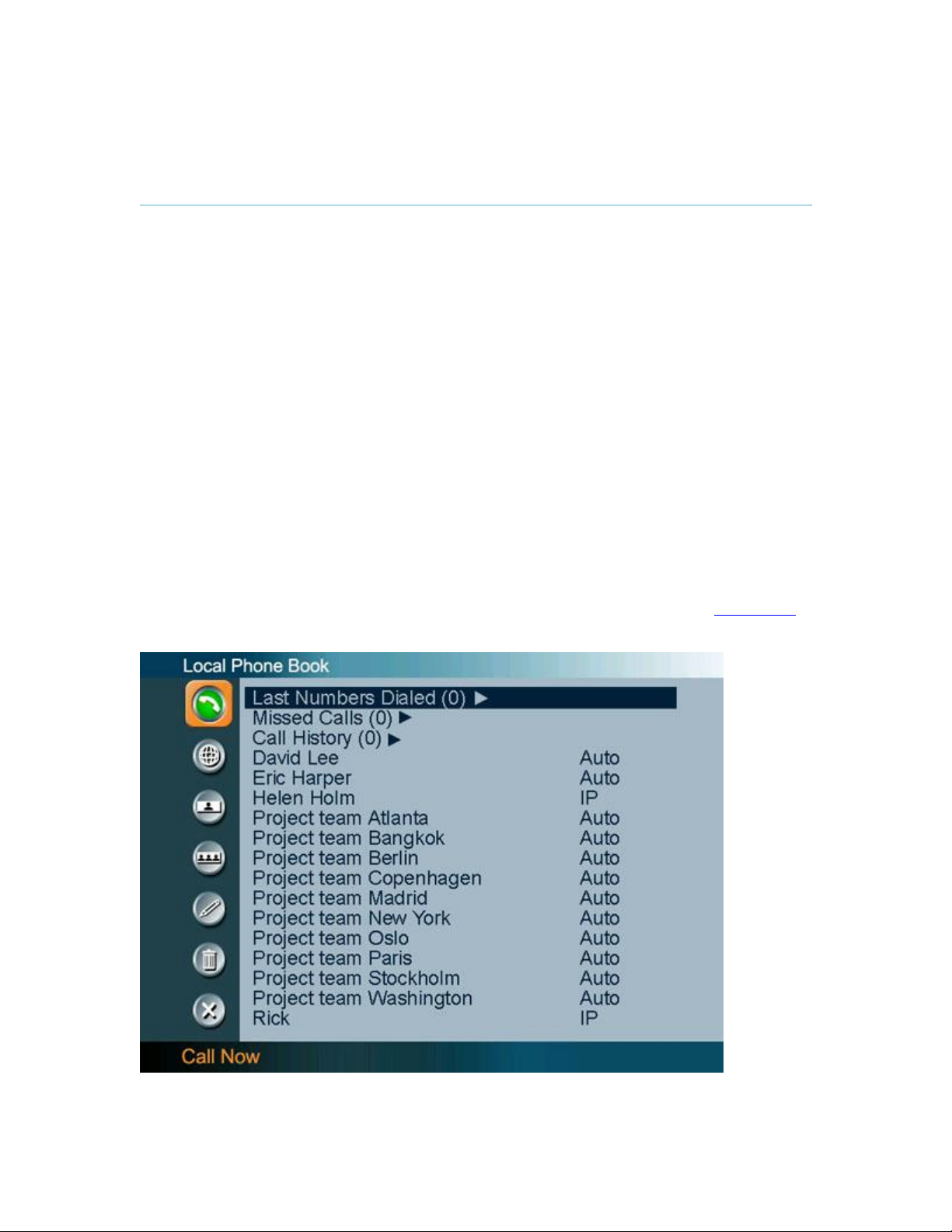
3.9.1 Local Phone Book
The Local Phone Book stores up to 200 contacts.
The first entries in the Local Phone Book are:
Last Numbers Dialed which lists the latest calls made from this system
Missed Calls which is unanswered calls
Call History which shows all incoming (blue arrow), outgoing (green arrow) and missed
calls (red arrow)
Press the OK button on the remote control or the right arrow key to see the contents of the lists.
How to make a call using the Local Phone Book:
1. Find the desired contact using the arrow keys or searching on the first letter with the letter
keys.
2. Press the green Call button on the remote control, or press the left arrow key to select the
Call Now icon, followed by OK. The call will be set up as a video call or a telephone call
depending on the settings made when storing the contact. Alternatively, press the OK
button when the contact is selected. The Make a Call menu will then be displayed with
the name of the contact in the Dial Number field, and the Call Settings field will reflect the
call settings for this contact. It is possible to alter the call settings before placing the call.
The call will be set up as a video call or a telephone call as described in 3.5 Make a Call.
3. Wait for the call to connect.
58

General Use
Note that the telephone or video number of the selected contact is displayed at the bottom
line.
See 3.9 Phone Book on how to navigate the Phone Book.
From the Local Phone Book the following functions are available:
Call Now
Global Phone Book
New Contact
New MultiSite Contact
Back
When a contact is selected the following functions are made available:
Edit Contact
Delete Contact
59

D1335403_T7000_MXP_User_Manual
3.9.2 Global Phone Book
The Global Phone Book is available if the system is connected to an external management
system like the TANDBERG Management Suite (TMS).
These contacts can not be changed locally by the system, only from the management system. If
there is a need to modify the number or any settings of a contact before making a call, select the
contact and press OK on the remote control. The Make a Call menu is displayed and the settings
can be altered before placing the call. The changes are not saved.
Note that the telephone or video number of the selected contact is displayed at the bottom
line.
See 3.9 Phone Book on how to navigate the Phone Book.
From the Global Phone Book the following functions are available:
Call Now
Local Phone Book
Copy Contact to Local Phone Book
Search Global Phone Book
Clear Search
Back
60

3.9.3 New Contact
General Use
The New Contact function is available from the Local Phone Book, see 3.9.1 Local Phone Book
for details.
When the New Contact icon is selected, the New Contact dialogue box is displayed. Add a
new contact to the Local Phone Book by:
Enter Name by using the letter keys on the remote control. Input will automatically be
interpreted as letters. Toggle between capital letters and small letters by pressing the #
button on the remote control. For numbers, press the # button for one second.
Enter Number by using the number keys on the remote control. Input will automatically be
interpreted as numbers. Use a star as separator in IP addresses. For letters, press the #
button for one second. Toggle between capital letters and small letters by pressing the #
button on the remote control.
Alter the default setting of Call Type if necessary.
Alter the default setting of Network if necessary.
Alter the default setting of Bandwidth if necessary. For bandwidth 2x64 kbps or 2x56
kbps, two numbers are required, see Deafult Call Settings for more details.
Alter the default setting of Restrict (56k) if necessary.
Press OK to save.
61
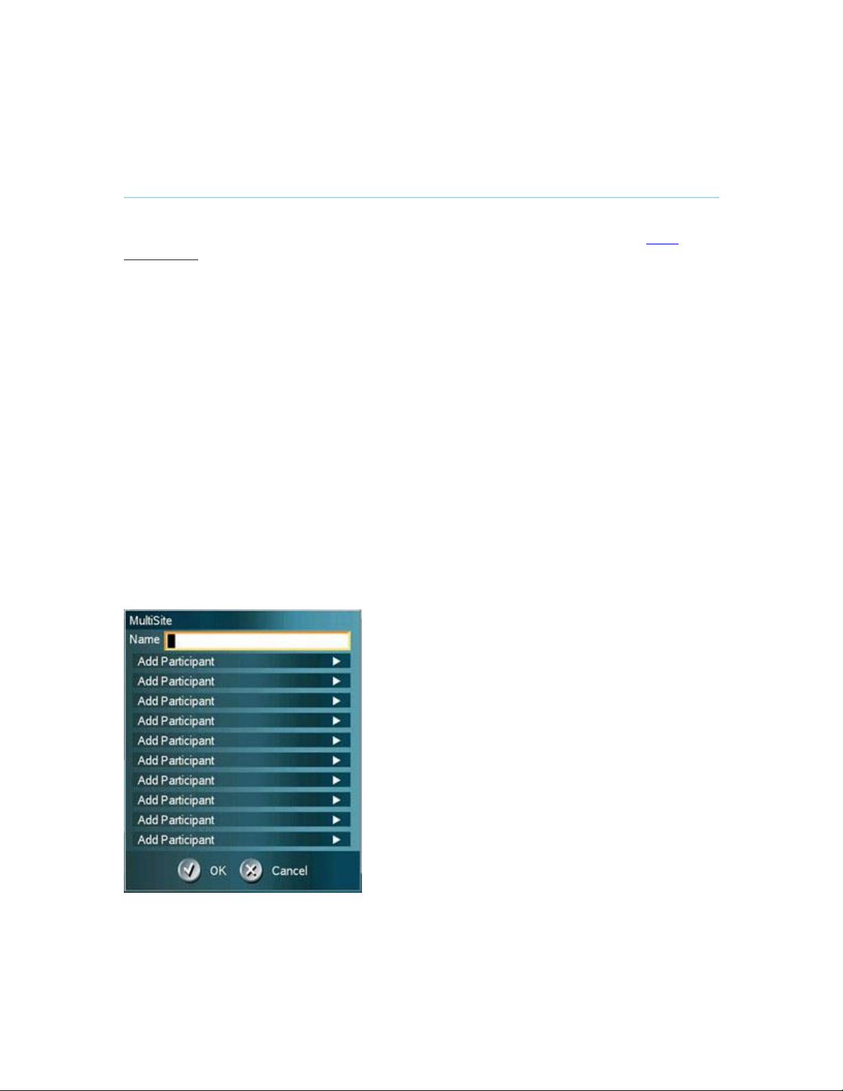
D1335403_T7000_MXP_User_Manual
3.9.4 New MultiSite Contact
(Optional feature)
The New MultiSite Contact function is available from the Local Phone Book, see 3.9.1 Local
Phone Book for details.
It is possible to pre-define the participants of a conference meeting as a MultiSite Contact. All
participants in the MultiSite Contact will then be connected automatically instead of having to call
the participants one by one.
The Local Phone Book can hold up to 50 MultiSites Contacts. The MultiSite Contacts consist of
participants that are already stored in the Local Phone Book.
It is possible to have up to totally 6 video participants and 5 telephone participants in a meeting.
How to define a New MultiSite Contact:
1. Open the Phone Book in the menu or via the Phone Book button on the remote control.
2. Select the New MultiSite Contact icon. The New MultiSite Contact dialogue box is
displayed.
3. Enter a name of the MultiSite Contact, and press OK on the remote control.
4. Select Add Participant. The contents of the Local Phone Book is displayed. Find the
desired contact and press the OK button on the remote control. Repeat until all the
desired participants are selected.
5. Press OK to save the MultiSite Contact.
Bandwidth for a MultiSite Contact call
When calling a MultiSite Contact, the system will try to call the participants with their specified
bandwidths. If the total bandwidth exceeds the systems maximum bandwidth, the system will
downspeed and distribute the available bandwidth equally for all the participants.
62

General Use
Example: In a MultiSite Contact there is one participant with bandwidth 256kbps and one
participant with bandwidth 384kbps. 512kbps is the maximum bandwidth of the system.
The two participants' bandwidth exceeds the maximum bandwidth. The system will then
downspeed so that each participant connects with equal bandwidth, i.e. 512kbps/2 = 256kbps.
63
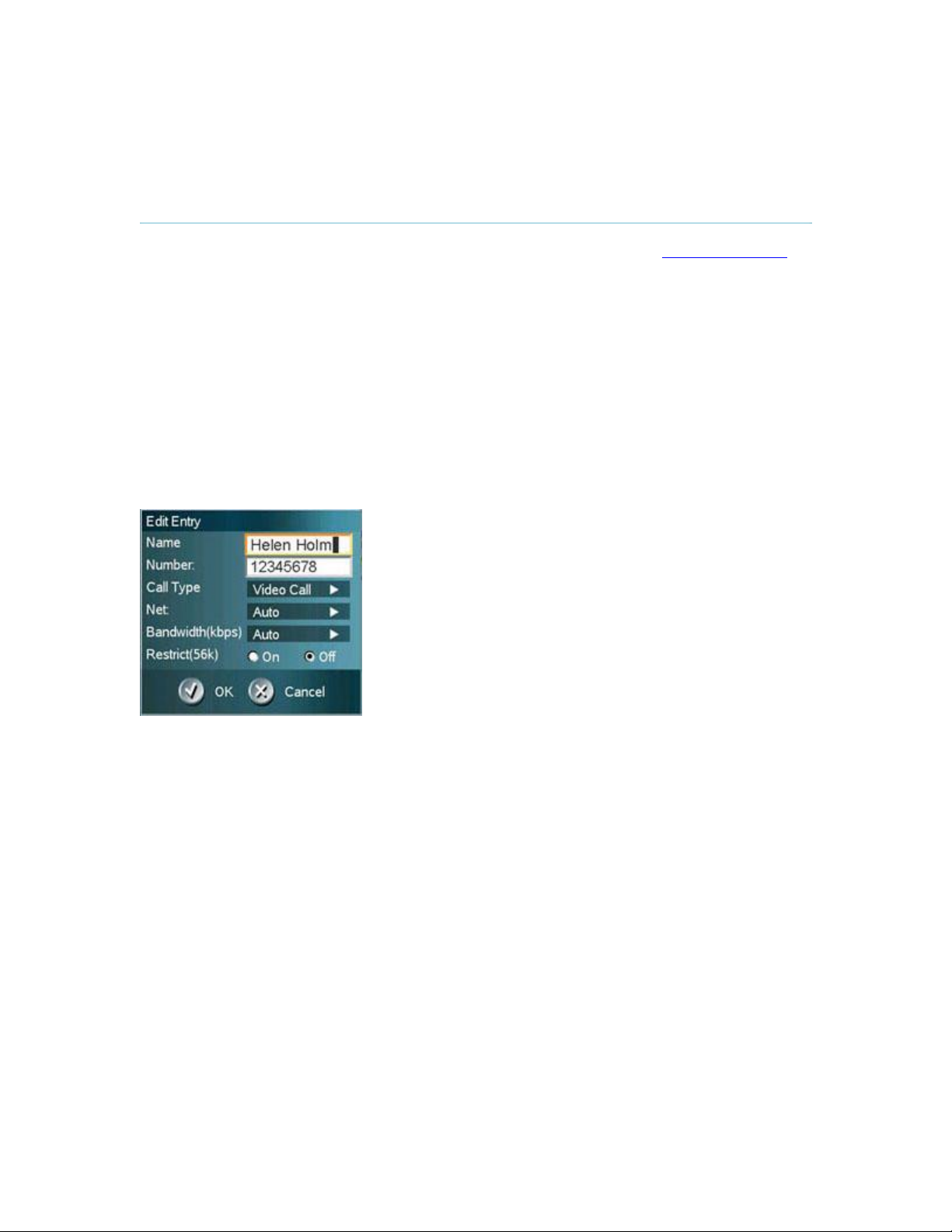
D1335403_T7000_MXP_User_Manual
3.9.5 Edit Contact
The Edit Contact function is available from the Local Phone Book, see 3.9.1 Local Phone Book
for details.
How to edit a contact in the Local Phone Book:
1. Select the contact that is to be edited.
2. Press the left arrow on the remote control, followed by the down arrow until the Edit
Contact icon is selected.
3. The current settings for this contact is displayed in a dialogue box. Alter the wanted
settings.
4. Press OK to save.
If the altered contact is part of a MultiSite Contact, the contact will be updated in the MultiSite
Contact automatically.
64

3.9.6 Delete Contact
General Use
The Delete Contact function is available from the Local Phone Book, see 3.9.1 Local Phone Book
for details.
How to delete a contact:
1. Select the contact that is to be deleted.
2. Press the left arrow on the remote control, followed by the down arrow until the Delete
Contact icon is selected. The Delete Contact dialogue box is displayed.
3. Confirm by pressing the OK button again.
65

D1335403_T7000_MXP_User_Manual
3.9.7 Copy Contact to Local Phone Book
The Copy Contact to Local Phone Book function is available from the Global Phone Book, see
3.9.2 Global Phone Book for details.
It may be wise to copy contacts that are often used from the Global Phone Book to the Local
Phone Book. If the Global Phone Book is large this makes them easier to find. However, note that
the local copy will not be updated if the Global Phone Book contact is changed.
How to copy a contact from the Global Phone Book to the Local Phone Book:
1. Select the contact in the Global Phone Book that is to be copied to the Local Phone
Book. See 3.9.8 Search Global Phone Book on how to search the Global Phone Book.
2. Press the left arrow on the remote control, followed by the down arrow until the Copy
Contact to Local Phone Book icon is selected.
3. A message box telling that the operation was successful will be displayed.
66

3.9.8 Search Global Phone Book
General Use
The Search Global Phone Book function is available from the Global Phone Book, see 3.9.2
Global Phone Book for details.
The Global Phone Book can contain an unlimited amount of contacts. Using search makes it
easier to find the wanted contact.
How to search in the Global Phone Book:
1. Select the Search Global Phone Book icon.
2. Enter search text in the dialogue box that appears and press the OK button on the
remote control. The system will list all entries that contain the entered letter combination.
3. Select the Clear Search icon to get back to the alphabetical Global Phone Book list, see
3.9.9 Clear Search. It is also possible to search on first letter in the Phone Book with the
letter keys on the remote control.
67

D1335403_T7000_MXP_User_Manual
3.9.9 Clear Search
The Clear Search function is available from the Global Phone Book, see 3.9.2 Global Phone
Book for details.
When a search in the Global Phone Book is made by using the Search Global Phone Book, only
contacts matching the search text are displayed. To return back to the alphabetical Global Phone
Book list, select the Clear Search icon.
68

3.10 Camera Control
General Use
How to move the camera:
Use the arrow keys to move the camera from side to side and up and down, see 3.10.1 Arrow
Keys.
Use the zoom button to zoom the camera image in and out, see 3.10.2 Zoom.
There are several ways to control the camera:
Use the Move Camera function in the menu to control the near end and far end camera, see
Move Camera for details.
Use Camera Presets, see 3.10.4 Camera Presets for details.
Use Automatic Camera Tracking, see 3.13.5 Camera Tracking for details.
Use the TANDBERG Tracker, see separate instructions included with the TANDBERG Tracker.
69

D1335403_T7000_MXP_User_Manual
3.10.1 Arrow Keys
When the menu is hidden, the arrow keys will work on the camera. If the menu is displayed, press
the Cancel button on the remote control to hide it.
Use the left and right arrow keys to pan the camera, and the up and down arrow keys to tilt the
camera.
70

3.10.2 Zoom
General Use
The zoom button on the remote control will zoom the picture in (+) and out (-).
71

D1335403_T7000_MXP_User_Manual
3.10.3 Move Camera
It is possible to move the near end camera by using the remote control or via the menu.
If the far end supports H.281, Far End Camera Control, it is also possible to move the far end
camera. Far End Camera Control is useful if e.g. it is not possible to see what a participant at the
far end is writing on their whiteboard.
How to use Near End Camera Control outside a call:
1. Select the Move Camera icon from the menu when outside a call.
2. Use the arrow keys on the remote control to pan and tilt the camera.
3. Press OK when finished.
How to use Near End Camera Control in a call:
1. Select the Move Camera icon from the menu when in a call.
2. Select Near End in the dialogue box that is displayed.
3. Use the arrow keys on the remote control to pan and tilt the camera. Zoom the image if
wanted, see Zoom for details.
4. Press OK when finished.
How to use Far End Camera Control in a call:
1. Select the Move Camera icon from the menu when in a call.
2. Select Far End in the dialogue box that is displayed.
3. Use the arrow keys on the remote control to pan and tilt the far end camera. Zoom the
image if wanted, see Zoom for details.
4. Press OK when finished.
Note that this function is only available if the far end side supports H.281, Far End Camera
Control.
For more details on how to control the far end, see 3.13.3 Far End Control.
72

General Use
73

D1335403_T7000_MXP_User_Manual
3.10.4 Camera Presets
Use Camera Presets to easily vary between predefined near end camera positions. This is useful
when pictures from many different camera positions have to be sent to the far end. E.g. in a
meeting there is a white board, a PC and a small meeting table. Use Camera Presets to move
between these camera positions in order to present the correct information to the participants at
the far end without having to move the camera manually every time.
The Camera Presets are available from the number keys on the remote control when in a call or
via the menu.
Each Camera Preset is able to store:
Camera position
Video source
Audio source selection, see Audio for further details
How to save a new Preset directly from the remote control:
1. Move the camera to the desired position. If storing a video source as a Camera Preset,
press Presentation on the remote control.
2. It is possible to store one Camera Preset on each of the number keys, 0-9, when storing
Camera Presets from the remote control. Press a number on the remote control for 1
second to save the preset.
3. The new Camera Preset will overwrite any existing Camera Preset on that number.
How to save a new Preset via the menu:
1. Move the camera to the desired position.
2. Select Control Panel - Camera Presets in the menu.
3. Select Save New Camera Preset.
4. It is possible to store 15 Camera Presets on the numbers 0-14, when storing Camera
Presets from the menu. Enter a number between 0 and 14 and press OK. Confirm Save
by pressing OK once more.
5. The new Camera Preset will overwrite any existing Camera Preset on that number.
How to use Camera Presets directly from the remote control in a call:
1. Press a number on the remote control. The camera will move to the corresponding
position, or video source, stored on that number.
2. Camera Presets are deactivated when the camera is moved manually with the arrow
keys or when an input field is displayed on the screen.
Note that Camera Presets are only available directly from the remote control when in a call.
How to use Camera Presets via the menu:
1. Select Control Panel - Camera Presets in the menu.
74

General Use
2. Select Display Camera Presets and select the wanted preset with the arrow keys on the
remote control.
3. Press OK to select a Camera Preset.
The Camera Presets are available from the menu both in and outside a call.
3.10.5 TANDBERG Tracker
How to save presets for the TANDBERG Tracker:
1. Select which Camera Preset to be used on the TANDBERG Tracker.
2. Move the camera to the desired position to store on the tracker.
3. Select Control Panel - Camera Presets in the menu.
4. Select Save New Camera Preset. The camera presets between 10 and 14 are accessible
from the TANDBERG Tracker. Select a number between 10 and 14 and press OK.
Confirm Save by pressing OK once more.
For more information, see separate instructions included with the TANDBERG Tracker.
75

D1335403_T7000_MXP_User_Manual
3.11 Presentation
The Presentation Functionality in the system enables you to show other available video sources
as in addition to your Main Camera. This is perfect for meetings where you would like to show a
PowerPoint presentation for instance. You can even use arrow keys up and down on the remote
control to activate Page Up/Down on the PC (this only applies when using VNC).
Use Presentation outside a call to make a local presentation for the people in your own meeting
room. Use Presentation when you are in a call to make a presentation for the far end as well.
The quickest way to show a presentation is to use the presentation key on the remote control,
see 3.11.1 Presentation Key. The presentation key shows a predefined video source, PC is the
default. It is possible to change the presentation source in 4.3 Presentations Settings in the
Administrator Settings menu.
Choose Presentation from the main menu if you want to select a video source manually. The
Presentation menu offers you all the available video sources supported by your system. See
3.11.2 Presentation Menu to see all your available video sources.
76

3.11.1 Presentation Key
General Use
The quickest way to show a presentation is to use the presentation key on the remote control.
The presentation key is used to start (and stop) a presentation using the default presentation
video source. When holding the presentation key for 1 second, the presentation menu will be
displayed. It is possible to change default presentation source in Presentation Settings, see 4.3
Presentation Settings for more information.
How to show and end a Presentation using the Presentation key:
1. Press the Presentation key. The video source that is set as default presentation source is
displayed in full screen.
2. Press the Presentation key again to end the presentation and go back to main camera.
77
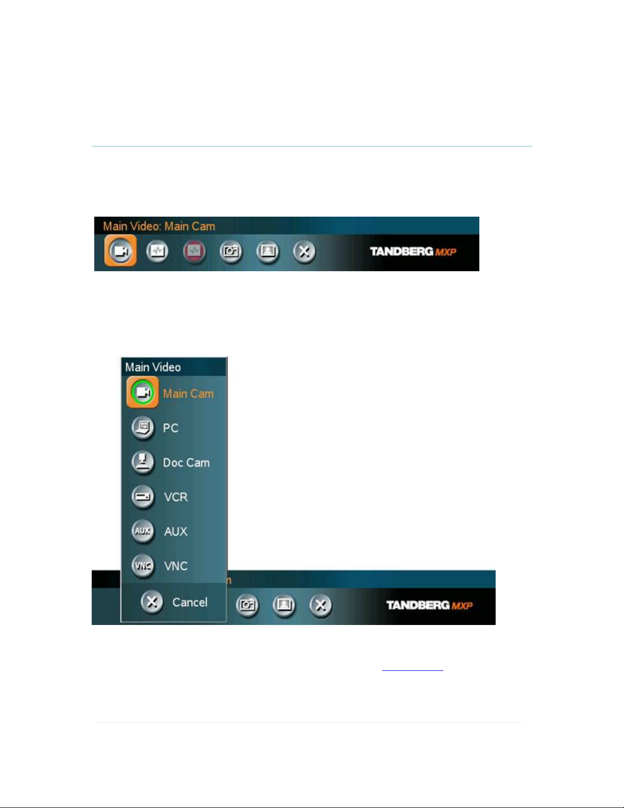
D1335403_T7000_MXP_User_Manual
3.11.2 Presentation Menu
The Presentation menu offers you all available video sources; Main Camera, PC, Document
Camera, VCR, AUX and VNC. All these sources can be used as Main Video or Presentation (Duo
Video / H.239). Press the Main Video button to change Main Video, press the Presentation button
to choose Presentation Video.
How to change your main video source:
1. Choose Main Video from the Presentation menu.
2. In the Main Video dialog box, choose your desired video source and press OK.
How to show a PC presentation in addition to your main video (Duo Video):
1. Remember to connect your PC to the codec (see 3.11.3 PC Presenter for details).
2. Choose Start Presentation from the presentation menu.
3. In the Presentation dialog box, choose a presentation source and press OK.
78
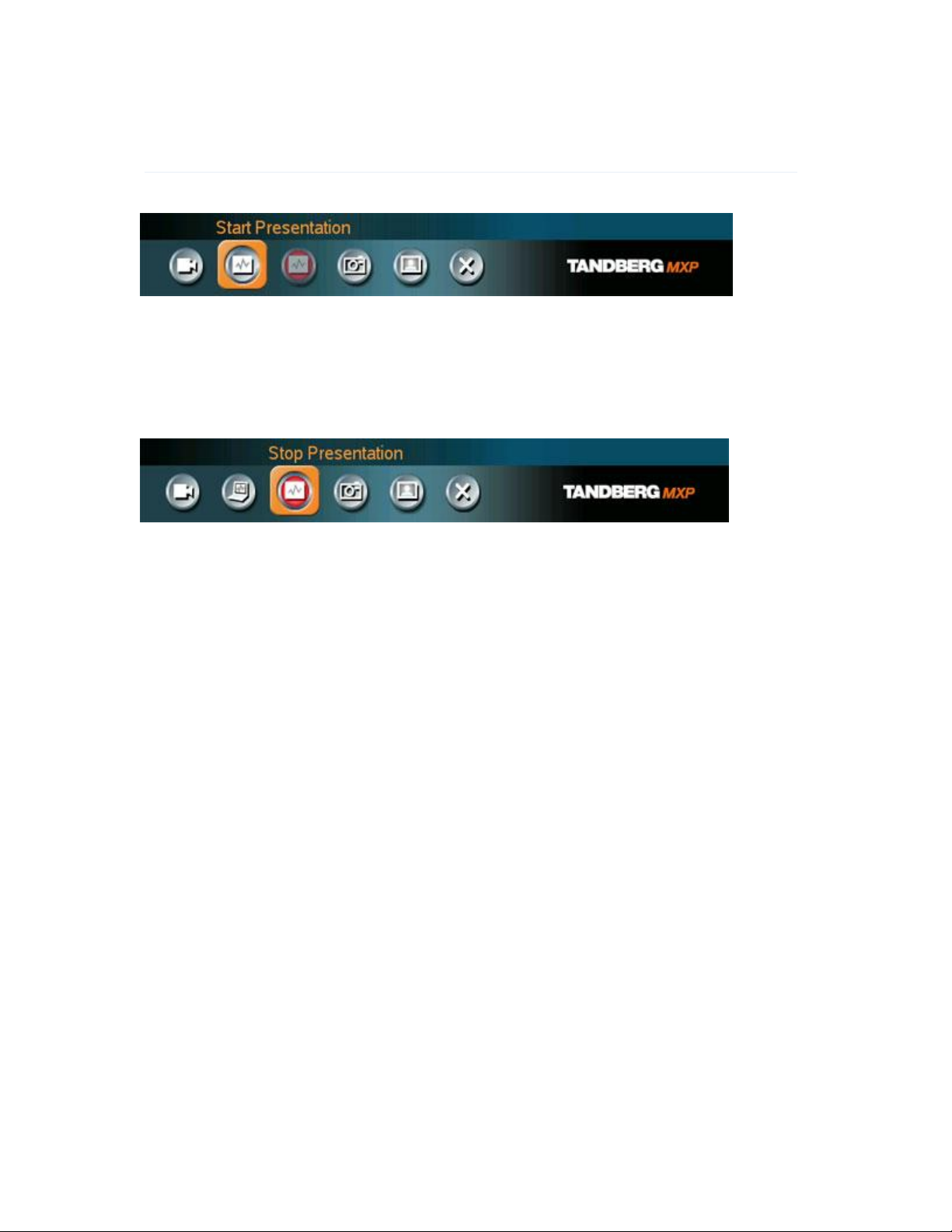
General Use
Note that Start Presentation is only available when you are in a call and the video systems
support Duo Video or H.329.
How to stop a Presentation (Duo Video):
1. Choose Stop Presentation from the Presentation menu.
2. Press OK to stop the presentation.
79

D1335403_T7000_MXP_User_Manual
3.11.3 PC Presenter (DVI/XGA Input)
(Optional feature)
Users often have their presentations on a laptop that is brought into the meeting room.
Remember to connect your PC to the codec before you press the Presentation button. Note that
the image will appear smoother on the system if your presentation is already displaying in full
screen on your PC prior to connecting your PC to the video system.
Plugging a PC into the system is made extremely simple through the PC Presenter, avoiding the
need for any additional hardware such as a projector, PC/Video converter or extra cables.
How to connect PC to the codec with the DVI/VGA cable:
1. Connect the VGA-DVI cable to the PC Presenter (PC DVI-I in) connector on the codec.
2. Connect the VGA-DVI cable to your PC (VGA Output).
3. When the PC is connected to the codec, hit the Presentation key to display the PC image
on the system.
If no PC image is displayed on your monitor, make sure that your PC is set to activate your VGA
output. On most laptop PCs you must press a special key combination to switch the PC image
from the PC screen to the video screen.
Note that the DVI/VGA input is compliant with VESA Extended Display Identification Data (EDID)
and will be able to reconfigure the PC’s screen settings if it is currently configured to a VGA
format that the system doesn’t support (see 5.12 EDID for more information).
VGA-formats supported on 'DVI-I in'. (VESA compliant)
SVGA 800x600 60,72,75,85 Hz
XGA 1024x768 60,70,75 Hz
SXGA 1280x1024 60Hz
80
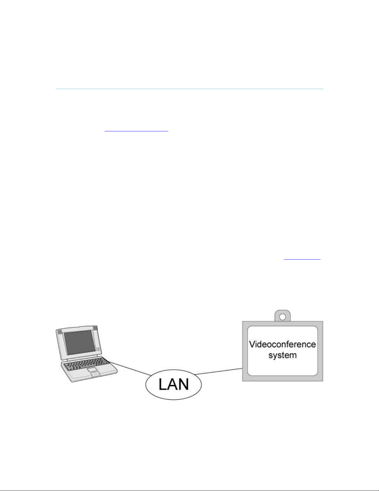
3.11.4 PC Soft Presenter and VNC
General Use
(Optional feature)
PC SoftPresenter is used to display PC images on your system without using a VGA cable (PC
Presenter). The system and your PC must be connected to the same LAN. In addition, VNC
(Virtual Network Computing) server software must be installed on the PC. Free software can be
downloaded from http://www.realvnc.com. Install the software by running the downloaded file.
How to configure the VNC Server software:
1. Select the following to setup VNC; Windows-Start\All Programs\Highlight
RealVNC\Hightlight VNC Server\Show User Properties
2. Select Accept Socket Connections.
3. Select Auto for Display Number. Display Number in the system must then have the value
0.
4. Enter a password in the Password-field. This must correspond with the VNC Settings on
your system.
How to show PC using the PC Soft Presenter and VNC:
1. Start the VNC software on your PC.
2. To use VNC, you must configure VNC Settings. Open VNC Settings in the Presentation
Settings menu in Administrator Settings.
3. Fill in the IP address of your PC, Display Number and Password. See 4.3.9 VNC Settings
for more information.
4. Press Save.
5. When you now choose VNC as video source in the Presentation menu, you will see your
PC using VNC. If a PowerPoint presentation is being displayed then you can scroll
through the presentation by pressing the up and down arrows on the remote control. VNC
settings will go back to default when the system goes to standby.
81

D1335403_T7000_MXP_User_Manual
3.11.5 Dual Stream (DuoVideoTF/H.239)
(Optional feature)
With Dual Stream you have the opportunity to show two different live video streams
simultaneously, main video and one additional source. This is handy when showing a
presentation. You see the live presentation and the live video of the presenter simultaneously.
When you start a presentation, Dual Stream starts automatically if both local and remote system
supports DuoVideo/H.239. If one of the systems does not support DuoVideo/H.239, no second
video stream will be established and your presentation will be shown as your main video.
DuoVideo/H.239 is available on all systems with Natural Presenter Package installed. H.239 is
the new ITU standard defining how to send two video sources simultaneously.
Example:
Start a meeting with main camera as video source. Press the presentation key on the remote
control to start a PC presentation.
PC will appear as DuoVideo in addition to main camera. End the DuoVideo presentation by
pressing presentation key again.
In Presentation Settings (see 4.3 Presentation Settings), you can put DuoVideo to Manual. That
means that DuoVideo will not start automatically.
Example:
Start a meeting with main camera as video source. Press the presentation key on the remote
control to start a PC presentation.
A dialog box appears where you can choose to show PC as DuoVideo or not. This is handy if
you not always want to use DuoVideo.
DuoVideo/H.239 and Bandwidth
Using DuoVideo/H.239, the quality will automatically downspeed to the optimal bandwidth. This
means that you need higher quality to allocate enough bandwidth for the two video streams.
DuoVideo/H.239 borrows bandwidth from main video. When DuoVideo is closed, the bandwidth is
returned to the main video.
Controlling camera, changing video source and camera presets in a DuoVideo call.
When selecting the Document Camera or PC, the system will automatically request floor when
connected to a MCU conference as MultiSite host or connected to an external MCU.
82

3.11.6 Take New Snapshot
General Use
The system can take a snapshot of your live video. Snapshot is handy when you are in a call with
a system that does not support Dual Stream. Use Snapshot to show a snapshot of your
presentation and continue the meeting with main camera.
How to use snapshot:
You find Take New Snapshot in the Presentation menu. Press OK to take a snapshot.
Snapshot is found on the Star key on the remote control. Press Star and you take a
snapshot of the current video source (current video is default snapshot source). You can
change snapshot source in Control Panel - Administrator Settings - Presentation
Settings, see 4.3 Presentation Settings. Note that snapshot does not work when you are
in an input field in the menu (the star key is then used to write the star sign).
Note that Take New Snapshot is only available when you are in a call.
Note that the Snapshot feature uses H.261 Annex D and hence will not work when using
H.264 videcompression
83

D1335403_T7000_MXP_User_Manual
3.11.7 Display Snapshot
The system stores the last sent or received Snapshot. The snapshot is deleted automatically after
the call.
How to display snapshot:
To view a stored snapshot, choose Display Snapshot in the Presentation menu. Press
the Display Snapshot button again to deselect it. When disconnecting the call, the stored
snapshot will be erased.
When receiving a snapshot, the snapshot is displayed in full screen. Press OK to escape
from the snapshot. The last sent or received snapshot will be stored in the graphics
memory and erased once the call is disconnected.
Note that Display Snapshot is only available when you have a stored snapshot.
84

3.12 MultiSite Services
General Use
A Multipoint Control Unit (MCU) enables several sites to participate in the same conference.
During a multipoint or MCU conference, the status line will provide information about the
conference.
You can make a multipoint conference in different ways. The MultiSite Services vary depending
on how you make the call, see 3.5.3 Add call for details.
Using the system’s internal MCU, MultiSiteTF
The system has an optional built-in MCU, which is called MultiSite. It supports up to 6 video calls
and 5 telephone calls including yourself. The MultiSite supports both Split Screen and Voice
Switched mode.
With MultiSite, you have the following services:
Request/Release Floor
Assign Floor To Participant/Release Floor From Participant
Terminal Names
Layout (Auto/4 Split/35+1 Split/Voice Switched)
85

D1335403_T7000_MXP_User_Manual
Using an external MCU that supports Chair Control (H.243)
With an external MCU that supports H.243, you have the following services:
Request/Release Floor
View Participant/End View
Chair Control
If you take Chair control, you get the following services:
Release Chair
Assign Floor To Participant/Release Floor From Participant
Disconnect Participant
Terminate Meeting
Using an external MCU that does not support Chair Control
With an external MCU that does not support H.243, you have the following services:
Request/Release Floor
Terminal Names
86

3.12.1 Request Floor and Release Floor
General Use
When requesting floor, your video will be broadcasted in full screen to all other participants in the
conference. Request Floor is useful when you want to speak or display something in front of all
participants.
Release Floor when you are done and make the floor available for other participants in the
conference. An indicator appears when you have floor and disappears when you release floor,
see floor indicator in 3.3 On-screen Indicators.
How to use Request and Release Floor:
1. Open the Main Menu by pressing OK.
2. Choose MultiSite Services and press OK.
3. Choose Request Floor and press OK. A Floor indicator will appear when you have floor.
4. When done, press the same button again, which now means Release Floor. The Floor
indicator disappears.
87

D1335403_T7000_MXP_User_Manual
3.12.2 MultiSite Layout
(Only supported by TANDBERG MultiSite)
With a TANDBERG MultiSite you can choose between the layouts: Auto Split, 4 Split, 5+1 Split
and Voice Switched view. Auto Split displays all participants on the screen simultaneously. 4 Split
displays the 4 last speaking Participants. 5+1 Split displays the speaking participant in a big
picture and the other participants in small pictures. Voice Switched mode displays the participant
that is speaking in full screen. Switch between these picture modes using the MultiSite Layout
menu.
Continuous Presence layout 4 split
Advanced continuous Presence Layout (5+1). In this mode the Intelligent Call Management will use 4*CIF resolution for
better clarity and H.263 video compression.
Voice Switched mode
88

3.12.3 Terminal Names
General Use
Choose Terminal Names to see a list of the participants of the MultiSite conference. Press Cancel
to go back.
89

D1335403_T7000_MXP_User_Manual
3.12.4 Chair Control
(Not supported by TANDBERG MCU or MultiSite)
As chairman, you have access to more MultiSite Services. Select Chair Control to assume the
role of chairman of the conference. Select Release Chair to end the role as chairman. A Chair
indicator appears when you have Chair and disappears when chair is released.
90

3.12.5 Assign Floor and Release Floor from
Participant
General Use
Assign Floor allows the chairman to select which of the conference participants that is to be
broadcasted to all other participants.
91

D1335403_T7000_MXP_User_Manual
3.12.6 View Site and End View
(Not supported by TANDBERG MCU or MultiSite)
View Site allows you to view any participant in the conference regardless of whom having floor
and chair. Choose End View to go back to normal.
92

3.12.7 Disconnect Participant
General Use
Disconnect Participant allows the chairman to disconnect any participant in the conference. In a
multipoint call, this is equivalent to disconnecting a participant from the end call menu.
93

D1335403_T7000_MXP_User_Manual
3.12.8 Terminate Meeting
Terminate Meeting allows the chairman to terminate the conference altogether. In a MultiSite call,
this is equivalent to pressing End All Calls from the end call menu.
94

General Use
3.12.9 More about MultiSite (embedded MCU)
(Optional Feature)
Calling in to a MultiSite
Any system can be part of a MultiSite conference by calling in to a MultiSite. The dial-in numbers
to the MultiSite depends of the network that is used.
To dial in to the MultiSite on IP:
Dial the IP Number or the IP Address of the system. All sites can dial the same number.
To dial in to the MultiSite on ISDN-PRI:
Dial the ISDN number of the system. All sites can dial the same number.
To dial in to the MultiSite on ISDN-BRI:
The MultiSite has specific numbers for each call that participates in the conference. To
find the dial-in numbers for the MultiSite, choose Information from the main menu and
open System Information from the bottom menu line.
Site 2 must dial MultiSite Number 2.
Site 3 must dial MultiSite Number 3.
Site 4 must dial MultiSite Number 4.
And so forth
Receiving calls to a MultiSite
When the MultiSite receives incoming calls you can accept or reject it. Pressing the green key is
equivalent to pressing Accept. Pressing the red key is equivalent to pressing Reject.
End a MultiSite Call
Ending a MultiSite Call is not very different from ending a normal point-to-point call. Use the red
key on the remote control or End Call from the main menu. The end call menu lists all the calls
that participate in the conference. To end a single call, select the call, press OK or the red key on
the remote control. To end all calls, press the End All Calls button in the menu.
Duo Video in MultiSite calls
In a MultiSite call, the MultiSite can transmit the Duo Video and/or H.329 to the other participants
that support Duo Video and/or H.329. This means that any participant can send Dual Stream and
the MultiSite will transmit it to the other participants. The participants that do not support Duo
Video or H.329 will only receive Main Video or only the dual stream dependent on which software
options installed.
Mix ISDN/LAN
A conference can consist of any combination of ISDN/IP sites.
MultiSite cascading
95

D1335403_T7000_MXP_User_Manual
By connecting MultiSite systems together, it is possible to connect even more sites in a cascaded
MultiSite (see example below). All connections can use any combination of ISDN/IP. The host
can connect up to 5 other video systems with MultiSite functionality. The cascaded systems can
connect to 4 other video sites. These systems will automatically run Voice Switched mode and
transmit a full screen image to the host. In this case you get 26 participants in the cascaded
MultiSite conference.
96

3.13 Control Panel
General Use
The Control Panel contains the features:
User Guide
Streaming
Far End Control
Camera Preset
Camera Tracking
Text Chat
System Information
Administrator Settings
Restart
97

D1335403_T7000_MXP_User_Manual
3.13.1 User Guide
The on screen user guide takes you through a quick step-by-step introduction to
videoconferencing. It gives the user basic skills in how to use the system.
Note: The Audio demo will only appear in the User Guide if a DNAM is connected to the
codec.
98

3.13.2 Streaming
General Use
Streaming lets you broadcast your meeting to participants on web. The web participants can
listen to the meeting, see snapshots, but not participate themselves. Snapshots of current stream
(if MultiSite), selfview, far end and DuoVideo streams are accessible via http. See Appendix 6 for
descriptions of the possible snapshot files.
How to use Streaming:
1. Choose Streaming from the Control Panel to open the Streaming menu.
2. Press Start Streaming from the menu line.
3. Press Stop Streaming to end streaming. Streaming will also end when you disconnect the
call.
4. Press Streaming Settings if you want to change streaming settings (see Streaming
Settings below)
How to view streaming from a PC:
1. After streaming is started, an easy way to view the streamed audio/video is to start your
Web browser and enter the IP-address of the streaming system.
2. After the Web page of the system is shown, click on Streaming. Alternatively, enter
http://<codec ip-address>/stream.sdp
Streaming Settings
Address
Address Port
TTL/Router
Hops
Streaming
Source
Address is defined as the IP-address of a streaming client, streaming
server or a multicast address. Giving an address in the range 224.0.0.1-
239.255.255.255 will broadcast the stream to any host that has joined
the specified multicast group. Specifying normal broadcast address
255.255.255.255 will broadcast to any members on the LAN.
If several codec’s are streaming to the same IP-address, different ports
have to be used in order for the client to know which stream to receive.
If the first codec streams on port 2240 and the second codec on port
2250, the client has to specify which port to listen to. Video is
transmitted on the specified port; audio is transmitted on the port
number 4 above the specified video port, in this case 2244 and 2254.
This is used for streaming data to limit how many routers the data
should pass before it is rejected. If TTL is set to 2, data will not traverse
more than 2 router hops.
Auto: Enables streaming of both local and far end video.
99

D1335403_T7000_MXP_User_Manual
switching (the site that speaks is streamed).
Local: Only the local video will be streamed.
Remote: Only the far end video will be streamed.
Local and far end audio is always streamed.
Allow Remote
Start
Announcements
Video Rate
Streaming
Password
On: Streaming can be started from external user interfaces like
the Web-browser or Telnet session.
Off: Streaming can only be started from the Video Conferencing
System User Interface using the remote control, or by using the
Data port. This will prevent activation of streaming using Web
browser or Telnet sessions. See also Password section below
On: The codec will announce to the network that it is streaming.
This enables a streaming client (e.g. a PC) to connect to the
codec’s streaming session. Used by Cisco IP/TV.
Off: No announcement packets will be transmitted.
Defines the Video streaming rate from the system. Range is 16 kbps 320 kbps. In addition, audio (G.711) streaming rate is 64 kbps, providing
a maximum streaming rate of 384 kbps.
Set password so that only participants entering correct password will be
able to view the streaming session. Entering a password will prevent
unauthorized people from accessing the streaming session.
100
 Loading...