

JANDBERG
Serles
6OOOX
SER\/IGE
MANUAL
TANDBERGS
:'.:'-"-!,..,r/
g
/r
l
i.- I
:t(.;iJ,i
l.
l
i
,
3(r
RADIOFABRIKK
A/S

-\
CONTENTS
7.0
Mechanical
1.0
1.1
1.2 Brakes
I
I
I
tt
I
t'>,
1.3 Pressure Pad Adjustment
1.4
2.0
Alignment
2.1 Demagnetizing
2.2 Bias-
Tape Path
3.0
3.1 Visual
3.2 Mechanical Adjustment of Tape
Head Alignment
4.0
Model
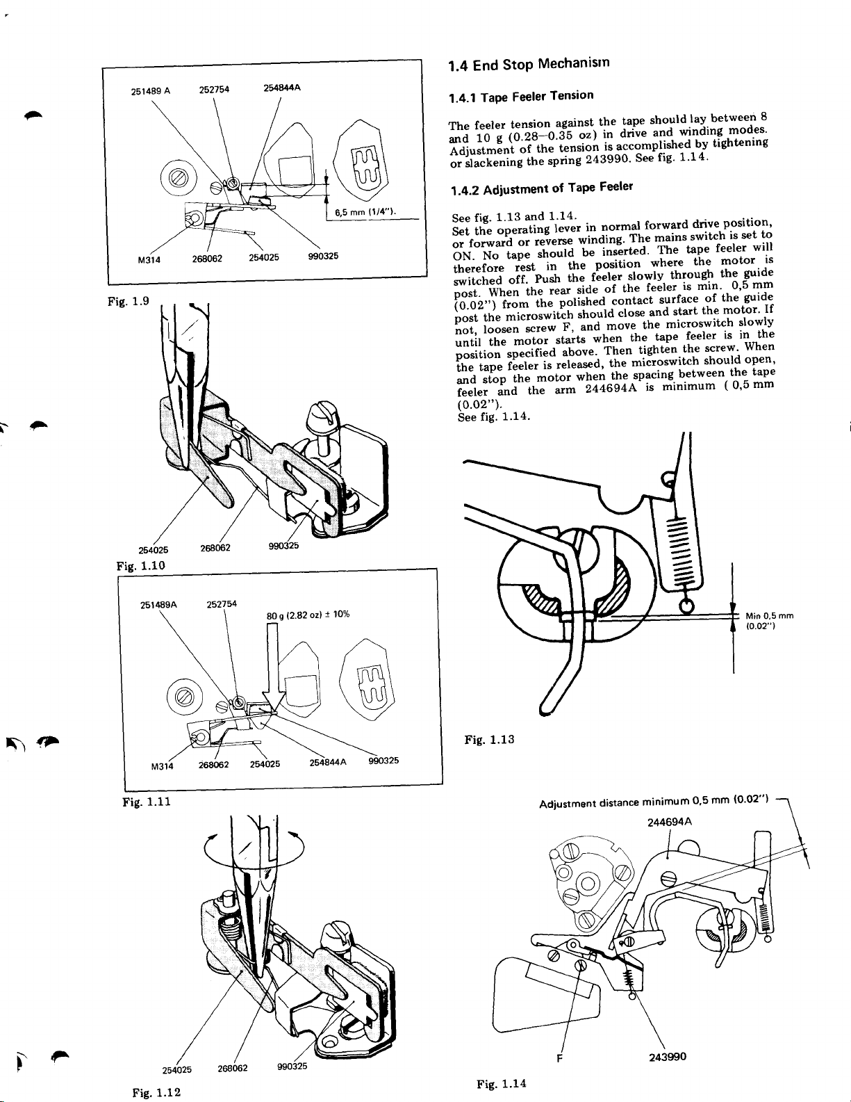
4.1 Playback Head
4.2
4.3 Bias Head
4.4 Erase Head
4.5 Model6021X
Head Alignment
5.0
Model
5.1
5.2
5.3 Bias Head
5.4 Erase Head
5.5 Model
6.0 Track
6.1 Model
6.2
Adjustments
Clutches
1.1.1 Take-up T\rrntable
1.1.2
Supply
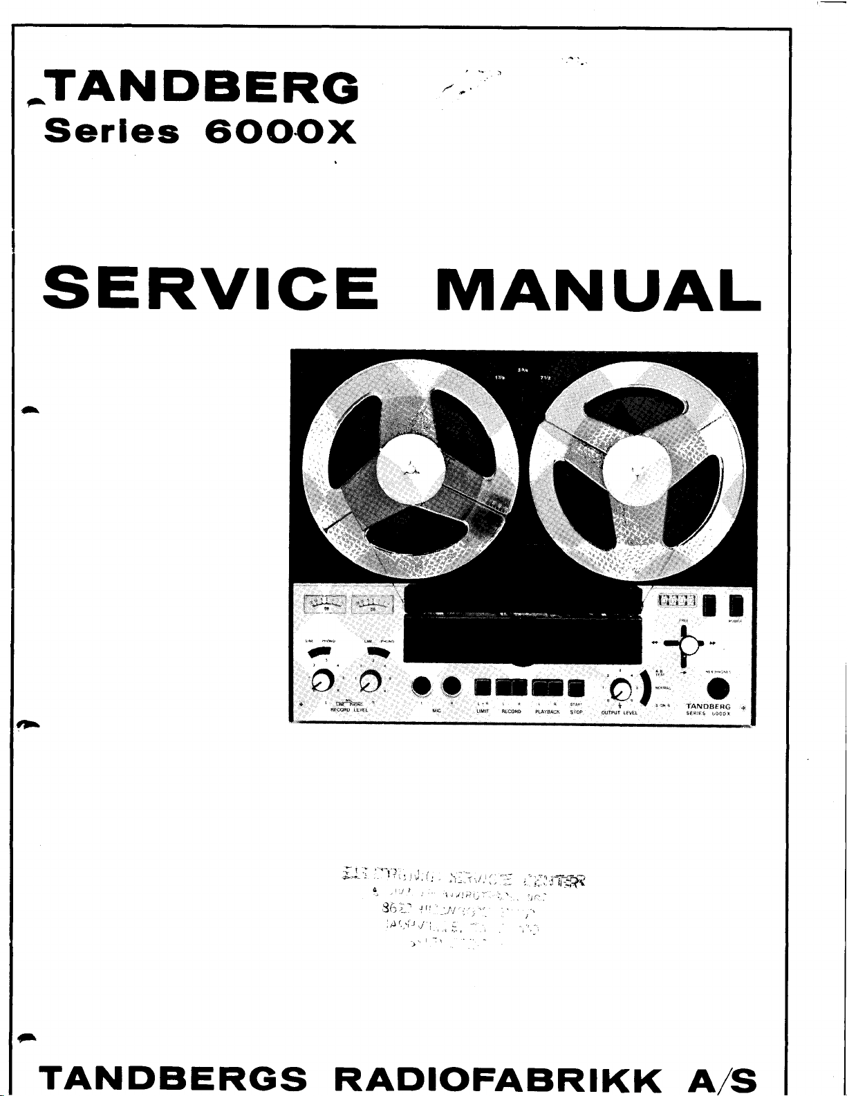
End
Stop
1.4.1 Tape Feeler Tension
1.4.2 Adjustment
and
2.2.1 Oscillator Frequency
2.2.2
Erase
2.2.3 Bias
6041X
Height
4.1.1
Azimuth
4.1.2
Record
4.2.1 Height Adjustment by
4.2.2
4.3.1 Vertical Adjustment
Height Adjustment
4.3.2
4.3.3
4.4.1 Height Adjustment
4.4.2
6041X
Playback
5.1.1 Height Alignment
5.1.2 Azimuth Alignment
Record
5.4.1 Height Adjustment
5.4.2 Azimuth Adjustment
Control
6.1.1 Record Head
6.1.2
6.1.3 Playback Head
Model
6.2.1 Erase Head
6.2.2
6.2.3 Playback tlead
T\rrntable
Mechanism
of Tape Feeler
Erase Circuits
Voltage
Current
Check
Tandberg Test Tapes
with
Adjustment
Adjustment
Head
Visual Inspection
Height
Adjustment
Measurement
Track
Horizontal Adjustment
Azimuth Adjustment
Without
Head
Head
6021X
6041X
Erase Head
6021X
Record
Head
by
Tandberg Test Tapes,
Path
Adjustment
7.1.1 Playback Level
7.1.2
7.1.3
7.1.4
7.1.5
7.1.6 Distortion
7.1.7
7.1.8
7.2
Tape Speed
7.2.1
7.2.2
8.0
9.0 Modifications
10.0 Lubrication
11.0 Illustrations
12.0
13.0 Transistor
14.0 Block
15.0
7.2.3
Adjustment
Tandberg
8.1 Playback
Record/Playback Curves
8.2
8.3
Readjustment
Indicators
8.4 Distortion
8.5
Control
8.5.1 Playback Amplifier
8.5.2
8.6 Pick-up
8.7 Limiter
8.7.1
8.7.2
9.1 Modification
to 230/115V
Modification
9.2
to Two-Track
9.3 Important
Introduced
Spare Parts
Tape
12.1
12.2
12.3
Printed Wiring Boards and
and Control of the Amplifiers
Adjustment
Record Level
Record/Playback Curves
Indicator Adjustment
Indicator Adjustment
and Amplifier Modes
Control of the Playback
Using Frequency Meter
Using Transformer
Voltmeter
Using Tape of Known
of the Amplifiers, without
Test Tapes
and Record Level
of Playback and Record Amplifiers
Record Amplifier
Amplifier
Adjustment of Limiting Threshold
Adjustment of Release Time
with
List for Tandberg
Recorder 6000X
Mechanical Parts
Screws,
Electrical Components
12.3.1 Transistors
12.3.2 Diodes
12.3.3 Rectifier
1
12.3.5 Poientiometers
12.3.6 Heads
12.3.7 Transfonners
Washers, Nuts and Circlips
2.3.4
Trimming
and Diode
Diagram
Adjustment
of Bias Current
Adjustment
in Record Mode
in Playback
Control 10
Record Levels
of
Curve
230/115V
from
Hz
60
operation
from Four-Track
Venion
Electrical Modifications
in
Series 6000X
Reference
Capacitor
Identification
6000X
Series
Amplifier I
or Counter 10
and Vacuum
Length
Adjustment
and
50 Hz
Part
Numbers
lViring Diagram
Ttrbe
9
I
9
9
I
9
I
9
10
10
10
10
10
10
10
11
11
11
11
12
72
12
t2
13
13
13
I4
1.7
77
2L
21
2L
22
22
9'
,t
22
22
23
23
24
^

1.0
MECHANICAL ADJUSTMENT
1.1
Clutches
1.1.1
Take-up Turntable
Normal
Set
the operating
with
the motor running.
between the
table
and friction disc
(0.02"-0.035").
fig.
1.1.
Forward
polyurethane
drive
lever
to
991009 lays between
If necessary, adjust
normal forward
Ensure that
friction
drive
pads
the clearance
under
screw A as
position
the turn-
0,5-0,9
shown in
mm
0,5-0.9
mm
{0.02"-0.35")
1
991 034
L
-
I
Control
Note:
The
presents
of Winding
All
controls
with the tape recorder
tion
control is
with
and
accomplished
two
optional modes
Torque
and measurements
empty
30 mm
reels
as
of
radius
placed
only.
shown
control.
must be carried out
in
horizontal
in
fig.
Force:
4O-80g
posi-
1.2, which
991017
Fig.1.1
il
-
991013
80
.rl
mm radius
Force:
15-30g
.arl
4
While measuring,
rotation. The instrument should
slow
movement in a straight
der.
Fig. 1.2 Control of winding force.
Fast Forward
Control of Fast Winding
Set
the operating lever
The control is
presents
Winding
two optional
the reel should be allowed
line
Torque
fast
to
accomplished as
modes of control,
forward
shown
follow the
tape
towards
Normal forward
the
winding
in fig.
1.3, which
to have a
recor-
drive
position.
Notc:
mode.
After a
operation,
20-30V"
longer
an increase
considered
is
period
normal.
as
of
of
the
continuous
torque by
+i
I

mm radius
\
30
80 mm radius
^
Force:
90-2509
\
\F
't\
Fig. 1.3 Control of
If the torque deviates
figure, check and, if
2673738.
spring
fast winding
necessary, alter the
torque. Fast forward winding mode
from
the specifications in the
pressure
of
Ensure that there is a clearance between the studs on
friction disc 991010
and
lever
991013.
See fig. 1.4.
min 0,1
(0.091")
mm
1.1.2 Supply Turntable
Tape
Control
of
Set the operating
The
control
presents
is accomplished
optional modes
two
Tightening
lever to normal
Tension
forward drive
as shown
of
control.
30 mm radius
in
fig.
position.
which
1.5,
991017
Fig. 1.4
991013
991OlO
261805
80 mm radius
Force:
O-99o
the
While measuring,
movement in a
straight
reel should
the
line towards
be
allowed
the tape recorder.
to
have a slow
rotation. The
instrument should
follow
F
Fig. 1.5 Control of tape
tightening tension.
Normal forward drive mode.

Fast
Reverse
Control
Set
the
The
control
presents
Winding
of Fast
operating
is
accomplished
two
optional
Force:
240-67
Reverse
lever
modes
0g
Winding
to fast
as
of
30
Torque
reverse
shown in
control.
mm radius
winding position.
fig.
1.6,
which
Force:
90-250g
80 mm
J
radius
1F{
Fig.
1.6 control
If the
figure,
spring 261805.
The
reverse
measured
1a--dius!
(fig.
1.2
See
Set the
Check
tumtable
screw
Set the
reverse
between
parts
(0.02"-0.04").
The
torque
check
difference
Winding
at
30 mm
If
necessary,
1.7),
or spring
Brakes
fig.
1.8.
operating
that the
is
approx.
D.
operating
winding
screw
on
operating
adjustment prosedure
of fast
reverse
deviates
and, if
See fig.
between
Torque
clearance
respectively.
C
If
necessary,
1.7.
should
radius),
alter
2673738
lever
to
1 mm
lever
to fast
and the
arm
991012
necessary,
winding
from
the specifications
Fast
Winding
be lesi
g (measured
or 50
p.esiu.e
the
(fig.
1.1).
normal
between
is
(0.04").
forward
Ensure
bottom
lays
adjust
equal for
forward
the
of
screw
torque.
alter the
Torque
than
of
brake
If
necesiary,
that
the
between
both turntables.
pressure
180 g (force
spring
drive
pad^
winding
the
hinged
0,b-1
C.
Fast
at
position.
clearance
reverse
in
the
and Fast
g0
mm
261g0b
and
the
adjust
or fast
delrin
mm
of
winding
Set
the operating
pressure
The
g (2.8
80
pressure
adjust
pair
of
Fig.
1.7
mode
pad
pressure
the
pliers.
of the
oz) !
arm
See fig.
lever
pad
tO 7o,
254025.
by
bending
1.12.
to
normal forward
against
the
measured
See fig.
the
tape rest
on
the
1.11.
spring
position.
drive
slould
end
If
necessary,
268062
be
of the
with-a
.)fl
1.3
Pressure
Set the
between
254844
fig.
1-.!. If
arm
254025
Pad
operating
pressure
the
should
be approx.
necessary,
with
Adjustment
lever
to neutral position.
pad
990325
6,5 mm
adju,st
of
the
pliers.
a
pair
and
(1/4")
clearance
See fig.
The
clearance
the
tape rest
as
shown in
by bending
1.10.
the
Fig.
1.8
991Ol7
(0.02"-0.04")
i)c
Mechanisrn
StoP
End
1.4
A
251489
-
(1/4").
mm
6,5
1.9
Fig.
;
I
TaPe
1.4.1
feeler
The
i;';
;;
Adiustment
;'"i;t;;;iline.p'l"g
Adlustment
1.4.2
1.13
fig.
See
S.;
or
bN."ff;di
ir,i;"i';"
ffi;;
oost.
id;t";'ii"*
i"".","1t*'-"";#qt.l""F*iml*n3iiil".n';"i
operating
il:
forward
"T;-i;
When
loosen
not,
the
until
",i.iirJii""i""iri"a
fi;;';;;;
and
feeler
(0.02").
See
stop
fig.
ii"r"t
and
1.14.
Tension
Feeler
the
of
and
reverse
or
.r'"ura
p.ro
the
ttt"
screw
against
of
1.14'
lever
rear
startJ-
tension
to.ie-o.fs
oii.
motor
it
motor
the
arm
the
tape
the
a'ii"
in
o')
tensioit
porislea-"ontact
released,
ii accomptishgd-u.v
243eeo'
Feeler
TaPe
normal
in
winding'
;;-;;e;hd'
*,J-poiiti"rr
tt'"
tla"
r'.i
"u"u"'
when
244694A-
t!"tet
"f
when
irten
the
the
the
Th-e
slowlv-
the
microswitch
see
forward
tighten
spacing.
shouldlay.between
winding
and.
1'14'
fig'
mains.switch
tape
rhe
Yh:T"--ll3
through
feeler-is
surface
feeler
tape
the
-
between
minimum
is
tightening
drive
reeler
min'
of
screw'
should
modes'
position'
set
is
motor
guide
the
0'5
guide
the
is in
When
open'
the
(
0'5
8
to
will
is
mm
the
tape
mm
F\
1.10
Fig.
1
80
g
(2.82
oz)
t0%
Min 0,5
{0.02")
mm
@
1.13
!f
1.11
Fig.
Fig.
DF
Fig.
1.12
Fig.
1.14

2.0
ALIGNMENT
-
It is-important
heads
on.the
results
on
tape recorder
the tape
ponse
2.1
Demagnetize
the
2.2
2.2.1
Connect
kHz),
oscillator
erase
by mens
2.2.2
Set the
VTVM
low-capacitance
Then
headhalf.
Set
check
The
recording
recording
2.2.3
Set
the
of a VTVM.
R407.
adjust
tape
new
polished
and the
Demagnetizing
heads.
Bias-
Oscillator
head. Adjust
Era* Voltage
check that
the
deviation from
Btas Current
the
voltage
path.
the
and
calibrated
a
frequency
by
means
of C404.
tape recorder
to
upper
tape recorder
the voltage
should
on
channel R.
recorder
tape
across
Adjust
Check
to 22Y
by
the
that
tape
tapes,
approx.
signal-to-noise
Erase
Frequency
probe.
the
contact
recorder
the
tape should
5 times
before
heads
measuring
and
Circuits
long
meter
half of
the same voltage
across
not exceed
upper
means
wave receiver
or frequency
pick-up
of
a
the
oscillator frequency
for
stereo recording
the
The
for recording
upper half
the voltage
for
stereo recording
half of the
the
voltage
voltage
of R410. Demagnetize
between
good.
is
ratio.
adjacent
voltage
across lower
To
be run
at normal
the
parts
placed
loop
erase head
should
appears
on channel
of the erase
measured
10V.
Proceed
bias head
to 22Y
the
tape
obtain
optimum
through
speed
friquency
before
(tuned
counter
to
around
to 8b.b kHz
and connect
by
means
be 80-120V.
across lower
in
similarly
and measure
by means
means of
by
head-half
heads
and
the
the
to
have
res-
aligning
256.5
the
to
the
of a
L
and
head.
stereo
for
and
and
IHMD
Fig.
3.1 Tape
3.2
Mechanical
Prior
essential
ment
Set the operating
screw holding
position
the
a
the
screw. The
the_ upper
247941.
Put
a tape free
way and
position,
99033.1
tapg
ls
$ightly
located
Align
pressure
perfectly.
path
to the
through
running
guide
electrical
to make the
the
latch 215563
determined
spring
and lower
from
set the operating
Adjust the
with
a screw
touching
adjacent to the
evenly through
post
roller
spring
2, 3,
adjustment
screws
adjustment
adjustment
tape
path.
lever
on-e of the
run
to neutral
to
by
spring
pressure
points
damages
lever
azimuth
driver
as shown in fig.
capstan.
and
4 similarly.
234478
flanges
of tape
without
allow the latch
will
of
on the
to normal forward
position
the
to make
path
of the
sideways
position.
284478.
now
be equal
pressure
recorder
pressure
of
rest of
the tape
of the tape
If necessary,
the
Unscrew
Then tighten
roller
3.2, until
heads,
it
move-
to settle in
against
pivot
in
normal
drive
roller
path,
post
adjust
tape
-<l
is
the
the
1
run
3.0 TAPE
3.1
Visual
Load
the recorder
lever
dowly
that
the
screws (C)
tape
head
Operate
runs
without
Check
cor:ect.
flanges
forward
tape
bias
against
parallel
is
the start/stop
within
flickering
that
It
of
the
drive,
must,
however,
PATH
Check
with
normal
record
button,
of the
on
neither
tolerated
posts
drive
by
no means
a t-ape,
head
head.
when
to
the
head neither
on
the record
the
record
to the
the rims
height positioning
can
be
guide
or
as the
and
forward
touches
base
Also
head.
and check
pressure
side
of
that
the recorder
mechanism
bulge
move
position.
drive
the height
plate,
nor
check
pressure
of the
guide
the
the tape
is
at the
the
operating
adjustment
presses
thit
the
that the
wheel
rubber
wheel.
posts
touches
is in
normal
engaged.
flanges.
Checi
the
bias
tape
the
The
ln
is
rll'\
Fig.
3.2
Azimuth
adjustment
pressure
of
roller
--
(?4;
$'rF
4.0
HEAD ALIGNMENT WITH
TEST TAPES, MODEL
4.1 Playback
Set
the
VTVM to
4.1.1
Height Adiustment
Play
Tandberg
prerecorded
and with the
approx.
by means
obtained from
to
maintain the headfront
4.1.2
Azlmuth
Play
Tandberg
prerecorded
7 tl2
ips. Adjust
head
by means
indication
4.2 Record
4.2.1
Height
Insert a new
forward
parallel
run
play
a
of approx.
the
height with screws
maintain the headfront
4.2.2Heighl
Record
direction, then
and
dip
powder
visible
Fig.6.1
patterns
high
Adjust
and
as
or too low.
as
Head
recorder
each one of the
30 dB.
of
on
drive.
in
stereo,
it
four
shows
obtained
above
for stereo
phono
test tape No.
tape with
area corresponding
the
track 3
Adjustment
tape with 10
the VTVM
Head
Adiustment
tape, and start the recorder in
Check visually that
with the upper
Adiustment
in the opposite. Cut
into
alcohol
dark stripes
the
1.000 Hz recorded
Adjust the
screws
test tape No. 2.
the azimuth
of the
0,1 mm
well above
a solution
(Magna
correct
when the head is
and
height of
(A)
(channel
parallel
000 or 15
screw
is
obtained.
by Visual Inspection
track of the record head,
(4
(C)
fig.
parallel
by Track Meaurement
See). The
with spacings in lighter
pattern
perform
TANDBERG
6041X
playback
outputs.
1. This
to track
the
until minimum
R),
while endeavourlng
to
the tape.
This is a full
000 Hz
position
(B),
the tape appears to
If
mils).
while
3.1,
to the tape.
normal level, first in
off
grained
fine
of
a
tracks will
on the tape
positioned
new track
connect
and
is a full
at
3 reduced
playback
recorded
of the
until
necessary,
endeavouring
a length of tape
iron
measurement.
track
7 ll2
ips,
by
head
output is
track
playback
maximum
normal
with
adjust
one
oxyde
then
shade.
and the
either
too
4.3.2 Height
Set
the
locking screw
VTVM
the
bias
M
a
at
to
be
for the
Check that
the bias head
between the
record head. The height
critical, and
the mounting
raise the
4.3.3 Horizontal Adjustment
Connect
headhalves,
ing. Insert
the
bias head to the right.
Then
screwdriver towards the left hand side.
Induced voltage
maximum. Continue
until the
When the
(H)
while maintaining correct
head.
change
repeated.
4.4
Erase Head
4.4.1 Height
By
visual inspection,
mils) of the
the tape. Insert Tandberg
4OO Hz
channel R
grained
solution).
centre of the
adjacent tracks
adjust the height
screws
check.
Adjustment
tape recorder
(H)
across each one
head
highest
the tape runs freely in
bias head slightly.
a VTVM across each one of the record
and
a screwdriver in
pull
the
bias
position
Then
recheck the output
has
occured, the horizontal
upper half of
signal
(track
iron
Check that
(K)
and
fig.
up or down
possible
and that
head
bias
if the clearance
plate
for
set the tape
bias head carefully
(bias)
pulling
is reduced
has
Adjustment
check that
at 7 Ll2 ips well
3). Dip
oxyde
erased track.
powder
the recorded
are
erased, see fig.
of the
(L)
ref.
in record mode,
3.1, about
record
of the
means
by
reading
there
the
and
position
between
record
the
recorder
groove
in recording head
the head towards left side
10-15 7o
by
found,
been
horizontal
the erase head is visible
test tape No.
the tape in
and
Make sure
erase
fig. 3.1,
and unscrew the
turn.
1/2
head
of adjustment screw
on
groove
the
is
sufficient
mounting
of
bias
the
the
head is insufficient,
for stereo record-
I,
ref. fig.
by
below
thigthen
voltage. If
above
head
position
procedure
approx.
normal
a solution
alcohol
is
track
that
6.2.
by means
and repeat the
Connect a
halves. Move
the
voltmeter.
in front
clearance
plate
for
head is
bias
head and
3.1, and
means
increases to
a noticeable
0,25
9 and record
(Magna
positioned
parts
no
If necessary,
pull
of
maximum.
the
screw
of
has to be
mm
above
level on
fine
of
of
of
above
of
the
not
the
a
the
(10
a
See
in
the
the
D
{^
4.2.3
Azimuth
Load a new
tape speed 7 Ll2
Depress
volume
Record
Adjust
output from
compromise.
4.3
Bias
4.3.1
Vertical Adiustment
Move
the operating
position
drive
record
heads are
the bias head as required.
Adiustment
tape into
ips, a 15 000
playback
both
potentiometers
l,evel knobs for
the record head
both channels simultaneously or
Head
lever
and check that
parallel.
the tape
buttons and turn
to maximum. Adjust
approx. 150 mV
recorder
Hz
signal in
azimuth
slowly to the normal forward
If
screw for
head fronts of
the
necessary,
and
both
the outputs.
at
bend
record
playback
both Line
maximum
bias- and
the arm of
at
stereo.
best
4.4.2 Azimuth
Check
perpendicular
azimuth
This
adjustment
that
the
to
position
Adlustment
head
the
mounting
by means
not
is
critical.
front of
plate.
the
of
4.5 Model 6021X
The
alignments specified
model 6021X with the exception
which is
is superseded
supenseded by 5.1.1 and
by 6.2.2.
in
para.
erase
the
If necessar5r,
(K)
screws
4.0
are
paragraph
of
paragraph
ref.
valid
4.2.1,
head is
adjust
3.1.
fig.
for the
4.1.1,
which

5.0 HEAD
ALIGNMENT
TANDBERG
MODEL
5.1 Playback
Head
TEST
6041X
WITHOUT
TAPES,
a similar
dip
and alcohol
visible.
distributed
Readjust the
the azimuth
recording on
it into a mixture of
(Magna
The
spaces
equidistant across
alignment.
between
height
4 and 2.
tracks
glained
fine
See solution)
the recorded
position,
if necessary,
Cut the
iron oxyde
to make
the tape, ref.
the recording
tracks
and
tape
powder
should
fig.6.1.
recheck
and
be
back
meters.
Head
the
Alignment
the
of
screws
run
for channel
Alignment
a standard
head
until
Head
instructions
instructions
5.1.1 Height
The height
adjustment
the tape shall
lamination
5.1.2 Azimuth
Play
VTVM connected
playback
the
fig. 3.1,
ref.
output
5.2 Record
Follow the
5.3 Bias
Follow
playback head
(A), ref. fig. 3.1.
with the upper
flush
L.
azimuth
to each
the
by
maximum
given
given
is aligned by
alignment
output. Adjust the
azimuth
reading
under
under
the height
The upper
part
adjustment screw
obtained
is
paragraph
paragpaph
edge of
the head
of
tape
position
4.2.
4.3
with
on
6.1.2
Insert a
Hz signal
ing level in mono
and dip
a
prereeorded
of
(B)
the
fig.6.2. Adjust
necessarv.
6.1.3
Record a 1.000
500 Hz
recording levels.
track 2
should
signal
signal is heard.
The Erase
Playback
be heard. Raise
is heard. Lower
Head
full-track
from a
it into
(channel
generator, well
the
track is
the
Head
Hz signal on
on
signal
Turn the
Recheck the azimuth
prerecorded tape and
on
track
Magna
in the
vertical
track 3
R)
at
the
the
above
(channel
3
See
solution.
centre of the
position
tape
maximum
playback
playback
of the
1
track
(channel
around
head
position.
(channel
volume.
head
record
optimum
R). Cut
R)
the
Check'that
erased area,
erase head
L) and
at
optimum
play
and
No signal
if
1.000
the
if the 500
a 1'000
record'
tape
the
ref'
if
,-t
a
back
Hz
Hz
Head
Erase
5.4
screws
mils)
Azimuth
azimuth
adjustment
with
position
6021X
Adjustment
of
of the ferite
should
Adjustment
the
with the exception of
CONTROL
5.4.1 Height
The height
adiustment
min
tfO
erase head
the
5.4.2
Align the
azimuth
parallel
azimuth
Model 6021X
5.5
The alignments
model
is superseded by
6.2.2.Paragraph
TRACK
6.0
Model 6041X
6.1
is
the erase
of
specified in
4.2.
5.4.1 is superseded by 6.2.1.
head
(K
mounting
L) ref.
and
visible above
be
position
screws
the erase
Paragtaph 4.2.1
aligned
fig. 3.1.
the upper
for
core
of
(K).
plate for the heads.
head is
paragraph 5.0
the
the erase
The erase head should
not critical.
paragraph
is superseded by
by
Approx.
tape.
head
are
height
the
0'25
track of
by
valid for
5.2 which
the
be
The
-
-
Fig. 6.1
-
-
Too
high
Correct
Track measurement
Too high
:
:
of record
head
Too
Too
low
tn
low
Record Head
6.1.1
Record a 1.000
optimum
3 for approx. 5 seconds.
Hz signal
recording
level in stereo
from
Turn
generator
a
the
on tracks 1 and
A-test
tape around and
well
above
make
Fig. 6.2
Correct
Track measurement
of erase
tro
head

6.2
Model
6021X
7.1.3 Record Level Adjustment
l)a
6.2.1 Erase
The
screws
in stereo well above
full-track
See solution and check
symmetrically across the
record heads, if necessary.
6.2.2 Record Head
The
adjustment
stereo
prerecorded
check that the tracks
across the
6.2.3
Head
height of
height of the record
well above optimum recording
Playback
the erase head is aligned by the
(K
L) ref. fig. 3.1. Record a 1.000
and
prerecorded
screws
tape.
tape. Readjust the
Head
optimum recording level on a
tape. Dip the tape in the
(C).
Dip
the tape in Magna
adjustment
Hz
signal
that the tracks are distributed
tape. Readjust the erase
head is aligned
Record
are distributed
a 1.000 Hz signal in
level
on a
See
erase and the record
symmetrically
Magna
and
by the height
full-track
solution and
heads,
the
Insert a new tape
in
A-test. Adjust the recording levels for
indication of
playback
current
channel)
7.1.4 Record/Playback
para.
Ref.
playback
7.1.5
Indicator Adjustment
Setting of levels,
Adjust R124 for a 0
indicator
indicator.
Release
output voltage is still 1.5 V for
1.5V at both
buttons
means of R108
by
until an
8.2 for
curves.
and set
both
record a4OOHz
and
(B-test)
output voltage
the same as
F-224 for
playback
(left
Curves
adjustment
dB
buttons and check that the
phono
outputs. Depress the
and adjust the
channel)
of 1.5 V is obtained.
and control
in Record
paragraph
in
reading on left record level
the same
channels.
both
signa.latT
R208
and
of record/
Mooe
7.1.3.
reading
l12ips
VTVM
a
recording
(right
right
on
rF
il
'
^
{T--\
The height
adjustment
the upper edge of the lamination for
the
azimuth
7.0 ADJUSTMENT AND
of the
screws
position
playback
(A).
head is
The tape shall run
if necessary.
aligned by
parallel
channel L. Readjust
CONTROL OF THE
AMPLIFIERS.
7.1.1 Playback Level Adiustment
Connect a VTVM
tum the
recorder for 7 tl2 ips
No.
reading on both vacuum tube
7.1.2 Adlustment of Bias Current
Insert
Connect a
generator
for
to maximum and adjust the
150 mV deflection on
stereo recording. Adjust
on left channel VTVM, and R410 to maximum
channel
Note:
playback
4 and adjust R150
a new
VTVM
to Line
Hz
1.000
The
ally tuned
tances
upper
and 0.5
VTVM.
2-track model
C40?,
C408
bias-
and erase heads,
are
track.
each one of the
to
volume controls
playback
(L)
voltmeters.
reel of
good quality
Line Output terminals, and
to
Input terminals and set the
volt. Set the Output Level Controls
VTVM. Set the tape recorder
R407
bias- and erase
given
is also
and C126.
pF.
in
phono
to maximum. Set the
of
and R250
Record Level Controls
maximum deflection
to
equipped with individu-
heads. The values
C226
respectively. The
Upper
ouq)uts, and
Tandberg test tape
(R)
(Low
tape
labelled
are
number refers to
the height
with
for 1.5V
Noise).
signal
generator
to
for
on right
of
on the
capaci-
7.1.6 Distortion
Connect signal
meter to outputs.
Adjust
indicators.
distortion
indicator,
7.1.7 Indicator
Set the
check that the vacuum
phono
level
7.1.8 Control
Play
prerecorded
250-1 0. 000-5. 000ips
standard.
5 kHz:
tolerances t
two channels should
Record Level controls to
Modes.
tape recorder
output.
indicators read
back Tandberg
tape speed. The
generator
Record in B-test on both channels.
Check distortion
exceeds 37o, readjust recording level
paras.
ref.
The
+
1
7.1.3
Adjustment
Adjust P"422
0 dB.
Playback Amplifier
of
tape
with
1. 000-
output
2 dB. The
- +
tolerances
3 dB. The
be less than
400 Hz,
and
in stereo
tube
test No.
the following frequencies:
1 0 O- 5 O-
tape
difference in level
0.5 V and distortion
0 dB deflection on
to be
7.1.5.
in Playback and
voltmeters read
(L)
conforms
less
preamplifier
R445
and
This
3.
recorded
25OHz
with
10 kHz:
are:
other
3dB.
frequencies
is a full
than 37o. lf
(R)
between the
and
Amplifier
mode,
and
1.5V on
until
both
track
7 7
at
the N.A.B.
+
-
0
4
dB,
have
2
|

7.2Tape
7.2.1
Connect
and
7
ll2 ips
is indicated
Tolerance:
7.2.2
Connect a transformer 115/0.5 V
Hz
shown
(mains
Hz)
60
Deviation
the VTVM.
adequate meter
Clock
needle.
Read
this
Brake left hand turntable
too high
is
low tape speed.
Speed Control
Using Frequency
a frequency
play
back Tandberg
tape
speed.
%.
in
11.7o
Transformer
Using
VTVM
and a
in fig.
7.1. Play back Tandberg
frequency
at 7 712 ips tape speed.
from correct tape speed will
Turn the
the time
the speed deviation
particular
time from the
or too low. Increased deviation indicates
Meter
meter
Difference from
to the
50 Hz) or
deflection.
for
Output
10 comolete excursions of
or Counter.
or counter to
test
tape No. 11
Vacuum
and
phono
Output
No.
Level Control
per
in
nomogram in
slightly
phono
Output
(1.000
Hz)
correct tape speed
Tube Voltmeter
230/0.5
or
and the mains as
test
(mains
a
19
give
cent corresponding to
to
decide if tape speed
V,
50/60
No. 10 a
tape
frequency
a beat across
to
obtain
the
meter
|ig.7.2.
too
8.0
ADJUSTMENT
WITHOUT TANDBERG
Playback
8.1
at
Connect a
generator
channels and tuned
tape recorder is
The
112 ips
7
Noise).
Adjust the
output meters are 1.5
the
maximum. Replace
to
distortion rneter
(B-test).
reading
Replace the
meter and depress the
Adjust the
shows
terminal
stereo
Adjust R150
reading
the
Release
A-test) and check
still are 1.5 V.
shows
3 % distortion. Connect a
B-test"
on the output meters are 1.5
playback
THE AMPLIFIERS
OF
TEST TAPES
Record Level Adjustment
and
VTVM to each output
is connected
speed.
tape
recording
Adjust the recording current
and
the
and depress the
3 % distortion.
VTVM for channel R
recording current
proceed
(channet
volume controls ate set
push-buttons
that the reading
to
Hz.
to 400
for
up
set
Insert a
gain
controls until
V with
VTVM for channel
the
push
button
the recording as
L) and R250
Playback L and
terminal.
the Line Input of
stereo
good
the
playback
playback
R208 until the
by
VTVM to each
(channel
on the output
The signal
both
recording A-test, at
quality
the reading on
playback
R108
by
the distortion
with
discribed above
V. Make sure that
to maximum.
tape
controls
L with a
push
button
until
(B-test).
R
reading
output
R) until
(Stereo
R
meters
(Low
the
the
^+
I
I
i
in
+,1
2,A
play
1,5
Tandberg
l7o"
n ( rr
-:'-
50
or
Fig.7.1
r,0
, , ,
, l,
.,,J
20 25
At 3314 ips,
mains frequency). Proceed
accuracy.
tolerance:t
Speed
115
V) 60 Hz
230V,50H2
2,5
,0
1,.,,r.,,1,,,,1,,
I
F\9.7
test
for
as
'
60 Hz
0,5
I
I I I | | | |
40 50
l0
.2
tape
No. 10
7 1/2 ips to
lU
nr rreu
gL
0/3
SPeeddeviotion('A)
I I
hme
torr0
excursrons-
60 66
b
find
I
rn
seconds
complete
(50
speed
Hz
8.2 Record/Playback
Connect a
and R.
voltage,
kHz must be
voltmeters.
Set
30 dB below
reading as
Then
check
voltage
R407
If the voltage
to 1.000
means of R407 and
respectively.
reference level,
cies between
t
Perform the same
between
1 7/8
the output
frequency
In order
a band
the tape
record a
that
is too
for
2
from
dB
ips between
reference levels.
channel L and
Hz and adjust
40 and 20.000
differ by
VTVM to
recorder
optimum
the
is
Then
50 and
reference level.
levels
each
to
avoid
stop
or a
inserted
for 3 314
16.000
output
high, increase
low, alter
too
go
and recheck
16.000 Hz do not deviate
check
50
and
of the two channels
more than
Curves
phono
one of
interference
low
between the output and
(0
dB).
Hz signal at
voltage is within
R410
for maximum output
R410
back
for 7 112
Hz, and
9.000
the
from the oscillator
pass
filter
ips
stereo
Use
the
the
current by means
bias
for
channel
the input signal frequency
for channels L
400 Hz, reestablish the
to
the output level at
tps
then finally check
Hz. Ref.
3 dB.
outputs L
tuned
recording, level
output
same
!
2 dB.
R.
voltage by
more than
frequencies
at
level
4OO
should not at any
to 85.5
the
VTVM
level and
If the
of
and
frequen'
for
Hz.
R
4
7.2.3
Using Tape of Known Length
Insert
it
Tnloranne
tape of known length
a
back. Time taken
ips:
7
1/2
3
ips:120 seconds
3/4
ips:240 seconds
1 7/8
. 'l
7^
60 seconds
for
the whole
450"
(1144
length strould
cm) and
be:
play
8.3
Readjustment
Indicators
For readjustments of
paragraph
8.4
Ref.
7.1.3 and
Distortion
para.
7.1.6 for
of Recording
recording levels and
?.1.4.
adjustment and control
Levels and
indicators
of distortion.
ref.
'l

8.5
Control
of Playback
and Record Amplifiers
6
R12
(R226)
Irf
F\,
t
If
A
the specified
exceeded,
8.5.1 Playback
Connect
resistor
fig.8.1.
a signal
and a
tolerances for frequency respons€ are
playback
the
check
Amplifier
generator
100 uF capacitor
and record
in
series
playback
and
with a I kohm
amplifiers.
head, see
30
(24
)
VTVM
8.3
Fig.
Signa
generato
Fio A 1
(R235)
R'.r3s
Connect
playback
Set the
correct
rator
to
V,
i.e. 150 mV.
to
fie.8.2.
VTVM
also
volume
tape recorder
signal level,
Hz
4OO
+
1.
Fig.
'
,
\
-
.F"i!.'ulgu.'"'utor'and10dBdownbymeansofRecord
F
"
'
Connect
shown
each
oscillator.
with
below
Level
deflection.
fig.
Playback
8.2
Record
.5.2
channel.
input selectors to Line
8.4'
AnrPlifier
a VTVM
in
fig. 8.3 and
Short-circuit trimming
Set
0
indicator
dB
bontrols. Use
Check the
each
to
control to
apply oscilloscope. Tune the
and adjust the level
Check
curves
of the Line Outputs
maximum.
for
the
frequency response
stereo
playback.
to 20 dB below 1.5
ELEC'IRONIC
to each one of the head-halves
a signal
the tape recorder
generator
position.
deflection
400 Hz
frequency response
as
to
capacitor C404
for stereo
Set
i.e.
20
refurence
the
and set
To
ensure
gene-
according
DlV.
A
OI t,f,iV;F()T'{(]i-";}JC.
Hil-r-t/"'.."-ri:
862
i',1A5!-ivlLl-
6.t:.t
as
for
Input
Line
recording,
level 30 dB
dB
on
according
in
down on .,oi-
VTVM
to
S l@ ?@
mHr
Fig. 8.4 Recording
8.6 Pick-up
Set the
pick-up
unoperated
Controls
Adjust
VTVM
voltmeters connected
frequency
with the RIAA
SERVICT
Amplifier
input selector
selector
(stereo
to maximum.
with Record Level
(1.5
response conforms
CENTER
i'-';/').
t. i ;:
;:;.{zf
:li .
':'i
-,6i
"l
Fig. 8.5
'-
f
.
-+1
- I
'-
-
| 1---
.-
=1
-
-r-hi-i
?0
RIAA curve
curves
position MAGN.
in
amplifier
:
-
V
curve shown
1-
"i-l
'
1.,
-,
r'0
for magnetic
Curve
position PICK UP and
in
Set signal
Controls
dB).
20
the
to
within a
fie. 8.5.
in
-:
*
--
.-i
I
mode
).
generator
to 150
Check by
phono
Leave
Output
output that the
tolerance
-:
pick-up
the
buttons
all
Volume
4OO Hz.
to
mV output on
means of
of 2 dB

8.7.2 Adiustment
Release
of
Time
r00
2o
frequency
500
response
Fig.
to
8.6
DIN
50
Total
45511
8.7 Limiter
Set
8.7.1 Adjustment of Limiting
Set
Hz signals into
the level
button and adjust both R320
indicators. Increase
indicator reading does not
2
dB.
both
the
volume
input
to
controls to maximum.
outputcontrolsto maximum.
and
the
Line lnputs
on
0 dB
the
the input
increase
rm
?0m 5000
tolerances according
Threshold
in
amplifier
indicators. Depress LIMIT
+-
for
20
by
10000
mode
dB reading on
1
dB
and check
more than
m000 50000
Feed 400
and set
the
that
approx.
Connect
phono
and set signal
Depress
20
Then
mine
for
normal
See fig.
an oscilloscope
output. Feed 400 Hz signals into the line input,
dB.
abruptly decrease the level
by means of
the output
levels
LIMIT
level on indicator.
8.7. Adjust
button, and increase the signal level by
sigrral to
LITIIT
with
calibrated time scale
for
0 dB reading on
by 20 dB, and deter-
the oscilloscope
return
time to 0.7 s by means of R311.
the
Fig.
pattern
to approx. 1
8.7
to
the
the indicators.
the
time taken
below
dB
.+
+
MODIFICATIONS
9.0
230V to
9.1-9.2
motor
Motor
from
Hz
pulley, part
pulley, part
23O/115V 50
operation
l15V
operation, while motor
changed.
paper
part
uF, oil
be
No.:
SVo
No.: 263184.
No.:
paper
and description below.
capacitor,
1,5
motor capacitor,
Hz to
Connect
245777.
320V. Clamp
247452.
57. 320V.
part
Motor
Motor
No.:
9.1 Modification
2301115V 60
The transformer must be rewired when changing from 50
FIz
to 60 Hz
pulley
and motor capacitor have to
shown in
as
230V connections
230V, 50 Hz: Motor
230V,
or
fig.
capacitor: 2 uF, oil
for
Hz:
60
capacitor:
Clamp for
2631,84.
Fig.
9.1
230 V motor
257746
transformer connections
and
fl
-t'
q

115V connections
motor
part
pulley,
pulley, part
for motor,
pulley
number,
257746
115V, 50 Hz: Motor
v
115V, 60
When
tor, specify
capacitor: 8 uF, oil
for
Hz: Motor
capacitor: 6,5
Clamp
ordering motor
the
part
capacitor,
uF, oil
part
or
No.:
paper
5 % 220Y. Clamp
part
No.:
No.:
paper
No.:
clamp for
991040.
Vo
5
MoLor
Motor
22OY.
245777.
247452.
206773.
motor capaci-
Part
Record head
Playback
Erase
Bias
head
head
head
c726
c226
c407
c408
The numbers indicating the heads
for
heads.
the
Four-Track
c04-1
1R
c03-10P
D84-l8E
D90-038
pF
250
pF
250
pF'
3300
pF
3300
Two-Track
F82-07R
F83-11P
D87-20E
D92-04B
Add capacitance
I
until value
\
labeled
l'
J
are
on
is obtained
ordering numbers
head
9.3 lmportant
Introduced
From
serial number 2803700 output
altered from 10
specifications 45511. The following components
modified:
i
transformer connections
Fig. 9.2 1l-5 V motor
Modification from Four-Track to
9.2
and
Two-Track
Version
The
following components
modifying from
total capacitance is
four-track
labeled on two-track heads.
have to
to two-track.
be
changed when
The value
of
R423 changed
R428
changed
R429 changed
R432 changed
R434
changed
R435
changed
R436 changed
R437 changed
From
serial number 2803010
cations were introduced
Restistors R314
by capacitors
were introduced from base to emitter of
(10
C327
Electrical Modifications
in Series 6000X
kohm
from
from 22
from
from
from
from 10
from 82 kohm to
from
kohm) were omitted and
(2
uF). Resistors R346
5 kohm
to
kohm to 10
22
kohm
kohm to 10
22
kohm to 10
22
kohm
82
kohm
kohm to 5,6
10
in
limiter circuit:
the
impedance
to meet
kohm
kohm
10
to
to
to
the
kohm
kohm
47 kohm
5,6 kohm
47 kohm
kohm
following modifi-
Q305.
(100
were
DIN
were
replaced
kohm)
)F
F
1O.O LUBRICATION
l\'lotor:
The
The motor should be
3000 hours
every
The upper
Teresso oil 43 or 4? from
with a
and
the
lubricated after
of
use.
lower bearing
should
Esso.
approximately
lubricated
be
The Self
The turntables,
are
usually not
necessary
Teresso oil 43
Note: Utmost
Lubricating
mounted
be
to lubricate
only one
Excessive oil might seriously
drive.
Bearings:
the flywheel
in
self lubricating
lubricated.
or
from
47
must be taken while
care
fractional drop
the
Esso.
and
the speed
If,
however,
bearings
of oil
transfer-wheel
bearings and
it
should be
for any
affect the
reason, use
lubricating.
for each bearing.
should
Use
friction

ILLUSTRATIONS
1.0
1
WITH
REFERENCE
PART
NUMBERS
,a
264355/
260131
261+60'
262674
/
26'1655
262674
261355
265026
"62944
2607QO
264665
991007
l
.-.......--..-
_-_.
--_\
--<-264564
a.
--
----_
vEPTlcALPoslTloN'269772
260929
206296
2629
26i655
-263to9
--
260641
264169
261303
/262061
,/
\
A1
.f
EA(
QOSE
NUT
/-'
F
'i,
264494
2697A6
261149
+
991026
264E30
zsoao+
etortf
TAfl$StsBrs
218195
Fig.
2o2E5r
261970
11.1.
'1"
ToP
alal
t'
2667774
exterior
r <^A )QR
t
vtew
s
l,-
I
1".*.
i,@
\-@
ortouru
I
264190
O
240275
'g
{N(
259754
259600
264786
264494
2697A6
\
261A3c-
264119
9911u^26
+'r7\
t

99C305 215771
^
eeo23 3
,rLsz
\
(5oHz)
262969
991o^41
242331 / 99C2C4
9?1013
!7
2 697EF)
264973
991OO8
991Q14
991a17
260045
260153
261345
250828
-
----
-
-
269786
264973
202151
991034
991011
991013
990312
264270
263709
263932
261593
991030
259681
r
p
1o1/1o4
I
106/107
265096
990325
i
p
201/204/
I
206/2C7
252754
25i<8eA
26cJ42A
Fig.
zs<a<+a\
\
228244
18E-D84
12631e3 \250131
260131
11.3.
Top
11Q-CO4 10p-CO3
zszzs, I zszzs+
view
26116C^
with
covers removed
|
D3k
262532
262854
263c26
zaorz=lggpzrl
2416944
24e551
"12309
243013
242503
26O290
991A11
rs
254025
2s'1130
Fig.
c4B-D92
219234 261511
11.4. Tape path
and
\ 260577
pressure
2413124
1
23o185 990334
roller
arm

991003
264003
263134
991002
20E222
260620
262782
991012
262531
263,184
(1,5
-2f
9100 0
f )
9
991019
f
212036
26457E
<oa)at
-
)A7AA A
211539
991001
260289
1o51.0<
2697E6
264973
991014
262193
--;:r
991004
r
"'df
990233
^
'
991004
213997
\_'-
r
\L.
2a5771
"4rt52
(SOHz\
6oHz)
262236
Fig.
9903
11.5.
.1
257746
Bottom
2322
26
,ur"uo
|
lil/
{/t/
view
262969
f
,",
u, /
3
990201
,r,o,
991
"/,
034
*
.l
"t'1"
151
}r
269786
'%,
i:_26a973
t:t
f
1
(l
260124
D_1o1/1O4/
I
1o6/1o7
268e3?
2ol/2o1/
a
2A6i207
264932
261453
Fig. 11.6.
2598
Top
260131
61
view
460\ 2601
261
93
26
with upper
ff660
I
mounting
wJ
.l\
p
I
I
12
plate removed
31-4
261647
\
2634
86
26
1
120
?63309
263522
259881

,l
J
261865
248cJ27
2c2151
207977
26O706
261c94
^
262509
^
Fig.
11.7.
Upper
12.0
SPARE
The
numbers
identical
:lgr" 9".
not
available
12.1
Mechanical
with
the
as
PARTS
of
the
mechanical
the
numbers
figures
without
spare parts.
parts:
LIST
"n
e*istin!
FOR
TANDBERG
parts
on
tfi" p-"rt.
in-ihe'j*t.
the
figures
i.r'.io.".
990346
mounting
TAPE
are
p""t"
ti.t
.."
214342A
991027
plate
seen
from
RECORDER
Note:
Appty part
parts.
242sO3
underneath
6OOOX.
reference
24399o
numbers
244691
when
A
ordering
263952A
spare
l
I
I
I
I
I
rn
201957
202008
202t5t
202309
203250
206296
206713
207977
208222
208724
209306
21
1339
21
1418
21
2036
212066
21
5953
216599
217783
2t8767
2L9234
2l
9816
Shaft
Mains
cable
Microswitch
Shaft
Mains
cable
Window
Clamp
Roller
Transformer
Clamp
Spring
Pulley
Shaft
Holder
Nut
Pulley
Fin
Retainer
Nut
Shaft
Flange
Pressure
115
V,
7FT
Eceentric
230
Y
22Ocm
Counter
Motor
capacitor
Eccen.
segment
Microphone
Mains
cable
Transfer
Revolution
Lever
Operating
Cabinet
Turntable
Cooling
Tape
Turntable
Pressure
Ttrrntable
wheel
reel
roller
pad
arm
segment
w/plug
T301
arm
counter
lever
shaft
arm
housing
6,buF
assembly
L&R

224r85
224796
228244
Screw
Support
Connector
Vertical mounting
Sound-on-Sound
Microphone
feet
switch
f
230183
230629B
234960
237 482
240275
2402764
240406
2408794
242309
242337
242503
243013
243150
243990
2443424
2446944
245354
245777
24623t
24669L
247395
247452
24794L
248027
248157
248495
249306
249551
249737
2511 30
2574894
252tt5
252172
252496
252754
254025
2548444
255886
256864
2575t7
257746
259529
259600
259758
259773
259881
Shield
Roller
Washer
Spring
Connector
Screw
Spring
Plate
Spring
Spring
Arm
guide
Tape
Arm
Spring
Arm
I-cver
Suppressor
Pulley
Clamp
Washer
Clip
Pulley
Shaft
Insulator
Bushing
Connector
Suppressor
Guide
Clip
Link
Arm
Switch
Bearing
Clamp
guide
Tape
Arm
Support
Push
button
Connector
Drive
belt
Motor
Lamp
Selector switch
Connector
Plate
Jack
switch
Playback
Stop arm
Speed selector
Support,
Radio-P.up-Line
End
Record-playback
Ttansfer wire
End stop, transfer arm
Cam disc arm
End stop
Right
Bias head
End stop arm
End
End
Start-stop
Motor, 5O
End
Rec.
mm
9
Motor,60 Hz
Pressure roller
End
Adj. tape
26V
End
End stop lever
12.5 mm
Pressurc
Tape rest
Equalization
Flywheel
Adj.
Pressure
Pressure
Assy.
Remote
Counter
tLll23O
Counter and meter.
Pick-up
Phono
Fastening,
Microphone, US
head
erase head
stop
switch
stop
stop
switch
Hz
stop switch
potm.
(3/8")
stop switch
guide
stop switch
(112")
pad
arm
pad
pad/tape
control
V 50/60
printboard
shaft
head adj.
wires
Hz
version
24
f,
+
V 1W
260045
260t24
260131
260153
260289
260290
260361
260421
260476
260577
260620
260641
260700
260706
260735
260828
260850
260929
Meter
Transfer
Button
Arm
Side
Tape support
Friction ring
Washer
Spring
Bearing
Panel
Knob
Knob
Eccentric
Screw
Bracket
Lever
arm
plate
arm
:","_"i_o]11",..-
Record
Input switch
Limi ter-playback-stop
Input switch control,
Right
Neut.
Clutch L&R
Neoprene,
Input
Flutter filter
Front
Operating lever
Cueing
Tape
Support,
Start/stop solenoid
Rear
? nin<
and
position
start/stop
switch
control
guide
input
playback
switchr
indicator
level
right
solenoid
f

260965
261051
26L072
261094
261216
261302
261303
261345
26t453
26t460
261525
261647
261655
261805
84 1
261
261885
261913
26t970
261992
261999
262064
262157
262153
262215
262236
262244
262258
262322
262402
26248r
262509
262537
262532
262545
26267 4
262739
262782
262833
262854
262969
262983
262984
263026
263105
263734
263184
263278
263335
263486
263493
263522
263688
263709
263817
263838
26387
263888
263896
263932
264003
264054
264083A
264L26
264L62
264769
264L90
2642L2
264226
264370
264355
264420
264427
264485
Spring
Socket
Tension spring
Guide
Adj. screw
Terminal connector
Screw
Input
Input switch
Button
Stud
Transfer
Screw
spring
Coil
spring
Coil
Screw
Spacer
Cover
Disc
Spacer
Cabinet
Spacer
plate
Slide
Shield
Clamp
Steel ball
Roller
Knob
Contact
Arm
Lamp
Armature
Guide
Holder
Knob
Spring
Frame
Spring
Arm
Plate
Terminal
Screw
Control arm
plate
Side
Bracket
Clamp
Bracket
Plate
Transfer arm
Button
Spring
Screw
Button
Switch
Spacer
Bushing
4
Power
Shield
Guide
plate
Side
Spring
Tube
Spacer
Tape
plate
Top
Holder
Screw
Guide
Counter
Knob
Sleeve
Wafer
Insulator
switch
arm
post
spring
shield
plate
plug
switch
brake
arm
Cueing
Lamp meter
Pressure roller
Operating
Clutch-and-breake levers
pins
7
front
Cover
Control
Stop
control
Record,
Lifting arm
Control
rear,
Oover
Left clutch disc
Clutch and brake levers
End stop, feeler arm
Pick-up
Bottom
Thrust, bearing
Push button
Teak
Push
button
Stainless steel
Line input
Support, motor
Transfer
Flutter
Speed selector
Counterlamp
Tape
brake
Start/stop
Push
buttons
Speed selector
Upper,
Lower, operating lever
Main
board holder
Pull rod
selector
Speed
Speed selector
pins
3
Cabinet 5/8"
Switch. Sound-on-Sound
Right
PC
boards
Motor capacitor
Power
switch
Retainer,
Sound-on-Sound switch
Record left
Upper, operating
Topplate. 3 x
Power
switch
Sound-on-Sound
Function
Plastic,
Without
Radio connector
Power
switch button
Left
Bias head
Friction disc
Neoprene,
Insure rubber
Front
plug, rear
Mains
Start/stop
Slidearm
Lower,
Slide
arm
Sound-on-Sound switch
Motor terminal
cover
pc.
lever,
arm, left
right
channel
Sound-on-Sound switch
japanned
switch
flywheel
assy.
assy.
board
arm input switch
filter
holder
solenoid
rec/output
arm spring
lever
1.5-2uF
flywheel
selector switch-
operating lever
button
arm
start/stop
solenoid adj.
rec/out level contr.
damping
bearing,
lever
8 mm countersunk
solenoid
panel
control
Iower
small

264514
264542
264564
264578
264593
264645
264664
264830
264866
264894
264909
264930
264973
265096
265462
266072
266309
266496
266777 A
2673738
268062
268134
268932
269772
269786
990204
990233
990228
990305
990312
990325
990334
990346
991000
991001
991002
991003
991004
991005
991006
991007
991008
991009
991010
991011
991012
991013
991014
991015
991017
991018
991019
991020
991021
99t022
991023
991024
991025
991026
991027
991028
991029
99r030
991031
991 032
991034
991035
991038
991039
991040
991041
991043
Spring
Spring
Cabinet
Bracket
Bushing
Screw
Terminal
Foot
Spring
Holder
Post
Bracket
Stay
Tape
Tlansformer
Cover
Sleeve
Coil
Panel
Coil spring
Spring
Shield
Switch
Cabinet
Plate
Parallel
Ttansfer
Spring
Arm
Flywheel
Pressure
Pressure
Bracket
Main amplifier board
Power
Output
Input
Pick-up input
Line input
Cover
Cover
Turntable
Clutch
Clutch
Pressure
Start/stop
LeVer
Lever
Releasing
Arm
Arm
Bracket
Bracket
Spring
Spring
Spring
Spring
Housing
Foot
Bearing
Plate
Termnal strip
0perating
Lamp
Sound-on-Sound
Turntable
Disc
Cover
Cover
Clamp
Drivebelt
Holder
plug
plate
guide
arm
wheel
pad
roller
w/shaft
supply board
amplifier/osc. board
preamp
holder
board
roller
solenoid
arm
lever
board
board
arm
switch
slide
Usage
Pressure
Sound-on-Sound
Rosewood
Operating
Stop, operating
Vert.
4
Insert
Tape
Mains
Spring
Braking
Rear comers
Left
Power,
Rear
End stop lever
Start-stop
Rear
Right
Pressure
Start-stop
Input
Walnut
Fastening
Complete
Pressure
Tlansfer
With capstan
End
Compl.
Compl.
Compl.
Compl.
Compl.
Pressure
Heads
Supply
Disc, right
Disc, left
Assy.
Compl.
Clutch
Braking
With
Clutch and braking slide
Cueing
Sound-on-Sound assy.
Start/stop
Turntable, brake left
Turntable, brake
Flywheel, brake
Capstan, thrust
Turntable bearing
Plastic with rubber inserts
Upper flywheel, compl.
Record
Motor
With ball
Counter
Take-up
Tape
Pressure
Heads
Motor
Rubber
Tlansfer
roller
lever
mount
pins
rubber
brake
arm
cord
prcssure
lever
T1,
115-230V
solenoid
friction
pad
solenoid
selector
rear
roller
wheel
stop
roller arm
pulling
solenoid
interlock
tightening. Take
Roller
Capacitor,
wheel
arm
disc
arm
cover
rod
switch
lever
roller
right
Arm
8
arm
up tumtable
ptF
control arm
Valid below
Valid
below
Valid
below
Valid
below Ser. No.
No.
Ser.
No. 2806200
Ser.
Ser. No.
$-
f,
2806200
+
2806200
2806200

12.2 Screws,
Washers,
Nuts
and
Circlips.
Screws
^
214270 2,6x4 mm
210556
3 x 3
2tgt62 3
2t7280 4
269255 3 x 4
215951
204809 3 x 8
217632
251936 3 x 10
261303 3 x 10
214336
210622 3 x
206908 3 x
263336 3 x
214772
2t39I2 4 x
234529
204875 4 x
232367
200944
237267
227899
278675
269298
12.3
213767
Electrical
i
3 x 5
3 x
10
3 x
12
18
2O
30
4 x 4
5
4
x 7
18
3/16" nr.
t14"
1l+"
rl4"
3/8"
rl2"
314"
4
A
4
o
4
2
A
Components
230542
215320 3,2
237833 3,2
239651 3,2
231878
232826 3,2
201980 3,2
204ro5 3,5
235937
204013 4,2
214895 4,2
217752 4,3
202332
271216 4,75
231310
200299
277856 5,2
27 4930
209408 16
202072
Nuts
Washers
2,3 mm
3,2
4
4,3
5
5,2
6,2
5132"
mm
"
"
"
"
236346
208431
201003
2L7
540
2r3826
Circlips
2mm
D
I,
6"
12.3.1 Transistors
No. Description
Ref.
Notes
BC
Q101-6000x
Q102-6000x
Q103-6000x
Q104-6000x
Q105-6000x
Q106-6000x
Q107-6000x
Q10B-6000x
Q201-6000x
Q202-6000x
Q203-6000x
Q204-6000x
Qz05-6000x
Q206-6000x
Q207-6000x
6000x
Q208
+
Q301-6000x
Q302-6000x
Q303-6000x
QJ04-6000x
Q305-6000x
Q306-6000x
Q307-6000x
Q308-6000x
Q309-6000x
Q310-6000x
Q311-6000x
Q312-6000x
Q313-6000x
Q401-6000x
Q402-6000x
Q403-6000x
Q404-6000x
Q405-6000x
Q406-6000x
Q407-6000x
Q408-6000x
Q409-6000x
Q410-6000x
Q411-6000x
I
I
Q501-6000x
Q502-6000x
Q503-6000x
Q504-6000x
1488
BC
1488
BC
1O7B
BC
1488
BC
L47B
BC
1498
BC
1498
BC
1O7B
BC
1488
BC
1488
BC 1O7B
BC
1488
BC
1478
BC
1498
BC
1498
BC
1O7B
BC 1498
BC
1498
BC
1478
2N 5459
BC 153
BC
1488
BC
1488
BC 1498
BC 1488
BC
1478
BC
1498
BC 1488
BC
107B
BC
1478
BC 1478
BC
1478
BC
144
BC 139
BC
1488
BC
1078
BC
1488
BC
1O?B
BC 1488
BC
1O7B
AUY 21
BC 1O7B
BC
1478
2N 3053
Field Effect Transistor
EL
LLjTBLINlc,
A
DIV
8r,.1
r\ASi{'.,!!
Ot
iil',
/i;i:,r
$g11r7;gr
Eri{,,...;., -.
t.
r"i
i_c
i.
;.
j._,).:
.;i.
:,
,
,
r-
CENTER
:

12.3.2
Ref.
Diodes
No. Description
Notes
D201-6000x
D202-6000x
D301-6000x
D302-6000x
D303-6000x
D401-6000x
D402-6000x
D403-6000x
D501-6000x
D502-6000x
1N
lN
zF 6,2
1N 4148
1N 4148
1N 4148
1N 4148
1N 4148
ZF 24
BY 727
12.3.3 Rectifier
Ref.
No
Description Notes
B 40
Trimming
12.3.4
Ref. No.
C404-6000x 150-750
Capacitor
Descriotion
12.3.5 Potentiometers
Ref. No. Description
R3-6000x
R4-6000x
R101-6000x
R104-6000x
R106-6000x
R107-6000x
R108-6000x
R124-6000x
R150-6000x
R201-6000x
R204-6000x
R206-6000x
R207-6000x
R208-6000x
R224-6000x
R250-6000x
R311-6000x
R320-6000x
R407-6000x
R410-6000x
R422-6000x
R445-6000x
10
10
50
5 kohm
33 kohm
kohm
5
kohm
1
10
4,7
50
5 kohm
33
5 kohm
1 kohm
10
4,7
470 kohm
10
10
10 kohm
10 kohm
10
4148
4148
C2200
kohm
kohm
kohm
kohm
kohm
kohm
kohm
kohm
kohm
kohm
kohm
kohm
pF
Zener
diode
Zener
diode
Neg. Logarithmic
Logarithmic
Logarithmic
Neg. Logarithmic
Logarithmic
Logarithmic
Notes
Notes
"-|
fnq
1
Heads
12.3.6
Ref. No.
c04-11R
F53-1
1R
c03-10P
D84-18E
G51-18E
D90-03B
F82-07R
F83-1
1P
D8?-20E
D92-048
Transformers
12.3.7
Ref.
No. Description
TL-6000x
T301-6000x
T401-6000x
22
Description
Record Head
Record Head
Playback Head
Erase Head
Erase Head
Bias
Head
Record Head
Playback Head
Erase Head
Bias Head
Mains Transformer
Microphone Transformer
Oscillator Transformer
Four-Track
Four-Track*
Four-Track
Four-Track
Four-Track*
Four-Track
Two-Track
Two-Track
Two-Track
Two-Track
I
Valid
above: Serial
No.
Notes
280515
Notes
ls(

a
13.0
TRANSISTOR
AND DIODE IDENTIFICATION
a)
mru
'[17
illtil
]TI
0sc
2 N 5459
r|r
.s
V
BY
i
AUY'I
14.0
BLOCK DIAGRAM
127
SERIES
6OOOX
[I
AA
lll llr
TT
2F6,2
zF 21
rN
4148
f--,/ ,ftle
t-L*<>.
Bc 1478
BC 1488
BC
€
t49 B
4.
MIC
t,
*.ao*6
53
RECORD
plAya
s4:
PLAvB
ssr
59: SOUNo
POS2:
POS
3 NORMAL
POS
4 AA
SlO PHONO
Sll:
INPUT
S 12 :
I NPUT
MIC RECORD
RECORD
1
1-
(N
R
L r*
nr-!rl
ON S0UN0
S
0h S
-TEST
SELECTOR
SELECToR
SE
LECTOR R
LEVEL L
t
I
J
N
t
E
L
LEVEL R
G.,
PLAYBACK
800s1 E R
AMPLIFIER
F
All
switches
shown in unoperated position.
For
complete
switch
identification,
see wiring diagram.

v
t'
I
PRINTED
15.0
AND
iF
WIRING
WIRING
32!
c
-{''
$
BOARDS
DIAGRAM
c 3tt
c3ol
o3ol
Fffi
--\ -\
ry{,*S*F.H
i''i
#qd$$-H1l*g"EFBH
T
-TL-,r-.\
c3oE
*dfu..Ht€;.Y
Tffi'$x$qF6l*.
l-
?e?e
\ l[
6
cior
m
si*,
c3,?
ffi:riffi$"[ffi
ry
ffi
,1
'fs*'
Affib%ffi'"*'+ffiffiTffi
I
Michrophone
Uiiiidiir.ptifier
amplifier-,
line/phono-amplifier-,
board'reen
cl20
-01*
.{ rtl0
iiot
{09
O
@o
c.rls
?A
{r
Yn
e.r3
P,
{l-,,,P
tz
ct
dl-
ran
qmt6?
.{[-
416
c
-E-'
1trltrl$:.q
o
{lS
.-.{
O
C(05
r
r@}t
la
printed
*"J
.5t
-qt
li. SZ08| ?c106
---!
-1-
?l'.
\-,r'-^,4-l
l10l
rTY-Y\
tll.,o,
ar
.8Q9"
\*,b
0402
.allr.ll
t1@@},
I C401
ctqz
F,--l l------a
_,_r
r-
.$.
.t
b
o40l
side.
_1k-
a
_F-{rd.rt
L"J
C/.0.1
_l
G
limiterBoard
No.
'-!-
T
r-
and
18050
-
ct06
':S
&
la
rt@l
la
a)
a)
t1\\
|
Playback
amplifier
."*:Tl'Rl:tlffll,seen
-
printed side'
from
rri

s
'-
di
ffi:,8
,E
;
l"fuJ.
6':,;
s'
o
l*+uJ.
I
iF
i
H:
I#J.
ffi:,.H:
-q_.,**t6_1.
O
:::
uOOro,
tE
u,o,
l*
T
i,,.,
I
o
501
Qr
50?
ros
RIGHI
O
,.r
3ll
'Ogroz
''E
o
o
ararl
T-{
iff
sos
'_E*:l,il:
*:'i- .-j'E-.
.t
sol
?b
&.
I
a
'@1"-
@
ra ar
EOP
@
fimdlr
@
q503
Jf\
oooooo
504 505
503
-
tt[
-:[
&#
----.
C 20g
rj'i-
BS
1
cfo{
I
BT-
506 50?
.-llF
o
513
o
508 509
C2O'1 C
.-jF-..
i'fl;
ffifrilffiffi.
o*,
"PJl
oo
518
OrQ
115
OO
',61s
#]#
;':rt'ffi
ffiiKlF
211
Ji:*
-fts
*:'E-.
{po
I
c6fi
{$.
dr
T
J
I
|
l=
T3
q
I
t
D50?
519
5t6
r0
5u 512
{
;{-ff'
r
f
Rectifier
board,
seen
from
printed
side.
Board
No. 18038

It
,*
'*u
*..-'!
4$:
*
*
ffi
l$H
'e'i:
|f
F;..
l@
I tREC.
I I
r"",..'ADJ.'"
-*-
11
l
.-iF/
.:St02
-l
LEVEL
;LI
J.
-co-
?
e!.i?.,'rir.,.
}{F
J
*'
/
"rtHHt
++
HJHJ
e$*J-
uT35-'
Fll
ffiI,
,c:q;,
26
n
p,
?i
c121
:.r,"#
O-
ffi
+c2v2
*il1*
t
t
*
.
Phono
input
terminal
701
702
703
oooQ.,?
board,
seen from
70t,
'-#t,f3'
r^fi Hl'a!
h-
printed
side.
sl?(J
I
Board No.
I
.2
r8056A
lnput
terminal
board,
seen from
printed
side.
Board No.
18056
B

T
F
tv
I
I
i.-,
l--..,--l
I

:a'-----
Itr-.-*;#l
LEVEL
INOICATOR
5l
AMP
SPEED SELECIOR
/-r?rjiF{::\ 1
\ r-E-E:
:-.-Z
s96
th-.1-t1A
sg
^-H:'.E:a)
\:9rr
Sej
e-e
s-e-'i-'l
lt_,lsExstIrvrrY
lAl 1,.-,o
lilff
trT--
l3lxrovlctonv I
trf--hv
15 |
16l
l7l
l3l
lel
lol
REcoio
lAl
-
t"l
lfl
.so6rdno
lffiitl
lifil
'roPphr.m,kine
*ne
n-
llou-i1_u1_!.i
fREo
(irL
6r " t'.''".'"
L
R
c@.ilds
R.i3rot
ail oc drdt!
..hitd..'b r.tirror.
i
ret
'
rcl
'Po*l.otd
i
t.rh'hdr
'C@.tor
rUPtst
l.tr ch..n.r
to.k.
:Lor.t t6ck.n9ht
'd'col.d
nd'(otd
cn..h.r
pF
olh.''it.
ud.r.
'^
ohn
'n
r mh.
rilbd 3'9cl
d
't|€ut
{_[:_rJrfti]$ttc
i.)1Y.
*i."1
tJi- i.rl
;;i*i-'
ir
NAiii"iVlLi-r-
tAili)
.ooHr
I
^r
I
'moxJ
il----]
-]
l$hv
q.v
loohv
'.76v
rsonv
tsv I
6v
eov
o5.5kH'
t9.cd''d
r@mPF
!
'
x.t@@oh
I
I
I
I
I
I
I
r
s-.F11i€
"'l'..'y'0'
'r''
'
'
-
!'t'?-A9
'
0955
r-'2
cflNTER
SWITCH€S
L_ffii,'-]
uoemnu- Ys
*LECIOR
PNOiO
, ,
I
[l
't
ol
o
IN UNOPERATEO
ShOWN
AR€
rcSIIIOfl
CERAXrc+HAilETIC
r
13.
i-nr-D-
tl
tl
-lr
sr. oPER^lNC
LEVER
SWITCH
TAPE
u.mnas
RECOROER
*
mo*,*
1969
ml
r9?O G6
FES
1970
au6
SERIES
l8ll8-
HSP
CG
6OOOX
3

a
t
Tandbergs Radiotabrikk
TAN DBERGS
A/S, Kjelsas.
P.
O.8.9,
Tandbergs
RADIOFABRIKK
Koravoll, Oslo
I,
Radiolabrikk A/S, div.
A/S
Norway
Kjeller
4f
 Loading...