


 Loading...
Synology DiskStation DS1819+ 
Hardware Installation Guide

Table of Contents
Chapter 1: Before You Start
Package Contents |
3 |
Synology DiskStation at a Glance |
4 |
Safety Instructions |
5 |
Chapter 2: Hardware Setup
Tools and Parts for Drive Installation |
6 |
Install Drives |
6 |
Start Up Your DiskStation |
9 |
Add a RAM Module on DiskStation |
10 |
Add a Network Interface Card |
13 |
Replace System Fan |
15 |
Chapter 3: Install DSM on DiskStation
Install DSM with Web Assistant |
17 |
Learn More |
17 |
Appendix A: Specifications
Appendix B: LED Indicator Table
Synology_HIG_DS1819+_20180702
2
1Chapter
Before You Start
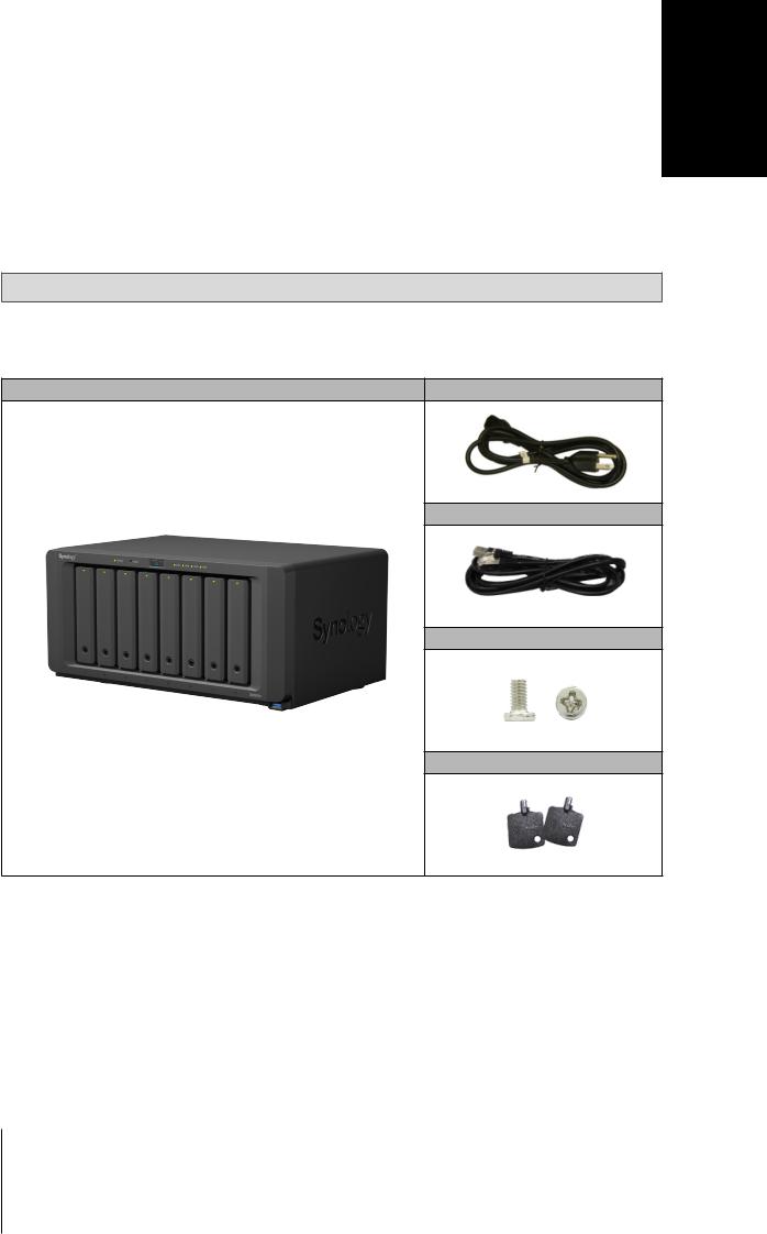
Thank you for purchasing this Synology product! Before setting up your new DiskStation, please check the package contents to verify that you have received the items below. Also, make sure to read the safety instructions carefully to avoid harming yourself or damaging your DiskStation.
Note: All images below are for illustrative purposes only, and may differ from the actual product.
Package Contents
Main unit x 1 |
AC power cord x 1 |
RJ-45 LAN cable x 2
Screws for 2.5” hard drives x 36
Hard drive tray key x 2
3
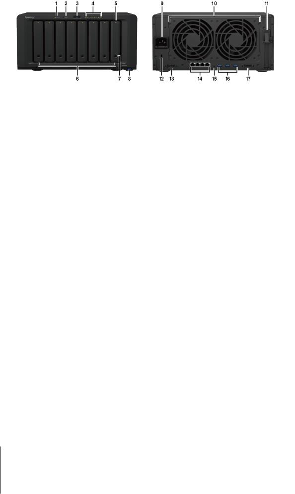
Synology DiskStation at a Glance
1 |
Status Indicator |
|
Displays the status of the system. For more information, see "Appendix B: |
|
|
LED Indicator Table". |
|||
|
|
|
||
|
|
|
|
|
2 |
Alert Indicator |
|
Displays warnings regarding fan or temperature. For more information, see |
|
|
"Appendix B: LED Indicator Table". |
|||
|
|
|
||
|
|
|
|
|
3 |
Power Button |
|
1. Press to power on the DiskStation. |
|
|
2. To power off the DiskStation, press and hold until you hear a beep sound |
|||
|
|
|
and the Power LED starts blinking. |
|
|
|
|
|
|
4 |
LAN Indicator |
Front |
Displays the status of the network connection. For more information, see |
|
"Appendix B: LED Indicator Table". |
||||
|
|
|
||
|
|
|
|
|
5 |
Drive Status Indicator |
|
Displays the status of the installed drive. For more information, see "Appendix |
|
|
B: LED Indicator Table". |
|||
|
|
|
||
|
|
|
|
|
6 |
Drive Tray |
|
Install drives (hard disk drives or solid state drives) here. |
|
|
|
|
|
|
7 |
Drive Tray Lock |
|
Lock or unlock drive trays. |
|
|
|
|
|
|
8 |
USB 3.0 Port |
|
Connect external hard drives, USB printers, or other USB devices to the |
|
|
DiskStation here. |
|||
|
|
|
||
|
|
|
|
|
9 |
Power Port |
|
Connect the AC power cord here. |
|
|
|
|
|
|
10 |
Fan |
|
Disposes of excess heat and cools the system. If the fan malfunctions, the |
|
|
DiskStation will emit a beeping sound. |
|||
|
|
|
||
|
|
|
|
|
11 |
PCI Express |
|
Supports one PCIe x8 slot (x4 link) add-on card. |
|
Expansion Slot |
|
|||
|
|
|
||
|
|
|
|
|
12 |
Kensington |
|
Attach a Kensington security lock here. |
|
Security Slot |
|
|||
|
|
|
||
|
|
|
|
|
13 |
eSATA Port 1 |
|
Connect external SATA drive or Synology Expansion Unit1 to the DiskStation |
|
|
here. |
|||
|
|
Back |
||
|
|
|
||
14 |
LAN Port |
Connect network cables here. |
||
|
||||
|
|
|
|
|
|
|
|
1. Press and hold until you hear a beep sound to restore the default IP |
|
15 |
RESET Button |
|
address, DNS server, and password for the admin account. |
|
|
2. Press and hold until you hear a beep sound, then press and hold again |
|||
|
|
|
until you hear three beep sounds to return the DiskStation to “Not |
|
|
|
|
Installed” status so that DiskStation Manager (DSM) can be reinstalled. |
|
|
|
|
|
|
16 |
USB 3.0 Port |
|
Connect external hard drives or other USB devices to the DiskStation here. |
|
|
|
|
|
|
17 |
eSATA Port 2 |
|
Connect external SATA drive or Synology Expansion Unit1 to the DiskStation |
|
|
here. |
|||
|
|
|
||
|
|
|
|
1 For more information about Synology Expansion Unit supported by your DiskStation, please visit www.synology.com.
4 Chapter 1: Before You Start
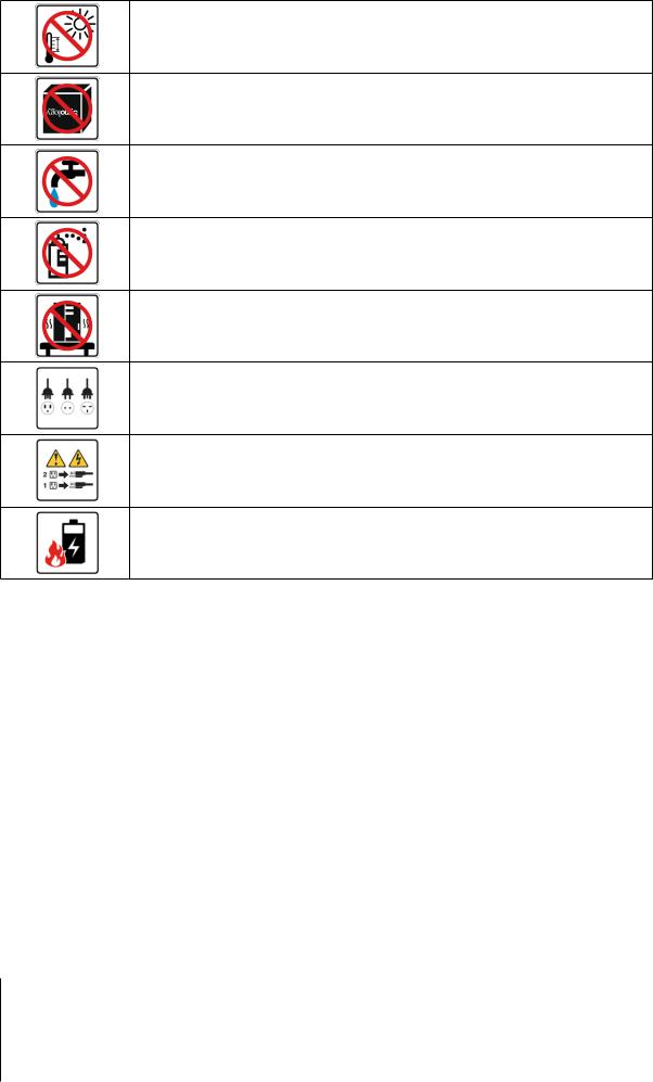
Safety Instructions
Keep away from direct sunlight and away from chemicals. Make sure the environment does not experience abrupt changes in temperature or humidity.
Place the product right side up at all times.
Do not place near any liquids.
Before cleaning, unplug the power cord. Wipe with damp paper towels. Do not use chemical or aerosol cleaners.
To prevent the unit from falling over, do not place on carts or any unstable surfaces.
The power cord must plug in to the correct supply voltage. Make sure that the supplied AC voltage is correct and stable.
To remove all electrical current from the device, ensure that all power cords are disconnected from the power source.
Risk of explosion if battery is replaced with an incorrect type. Dispose of used batteries appropriately.
5 Chapter 1: Before You Start
2Chapter
Hardware Setup
Tools and Parts for Drive Installation
•A screwdriver (only for 2.5" drives)
•At least one 3.5” or 2.5” SATA drive (please visit www.synology.com for compatible drive models.)
Warning: If you install a drive that contains data, the system will format the drive and erase all existing data. Please back up any important data before installation.
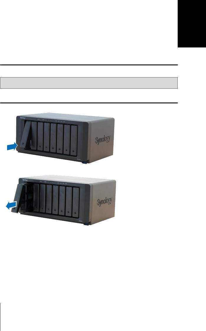
Install Drives
1 Press the lower part of the hard drive tray to pop out the handle.
2 Pull the hard drive tray handle in the direction as indicated below to remove the hard drive tray.
6
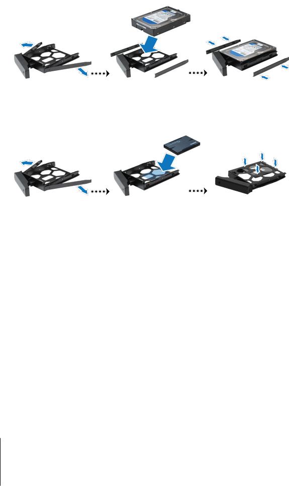
3Load drives in the drive trays.
•For 3.5” drives: Remove the fastening panels from the sides of the drive tray. Place the drive in the drive tray. Then insert the fastening panels to secure the drive in place.
•For 2.5” drives: Remove the fastening panels from the sides of the drive tray and store them in a safe place. Place the drive in the blue area (shown below) of the drive tray. Turn the tray upside down and tighten the screws to secure the drive in place.
7 Chapter 2: Hardware Setup

4 Push the upper part of the loaded hard drive tray and insert it into the empty hard drive bay.
Note: Make sure the tray is pushed in all the way. Otherwise, the drive might not be able to function properly.
5Press the handle in flush with the front panel to hold the hard drive tray in place.
6Insert the hard drive tray key into the hard drive tray lock, turn the key clockwise (to the "I" position) to lock the handle of the hard drive tray, and then remove the key.
7Repeat the steps above to assemble the other drives you have prepared.
8Drives are numbered as shown below.
Note: If you want to create a RAID volume, we recommended that all installed drives are of the same size to make the best use of drive capacity.
8 Chapter 2: Hardware Setup
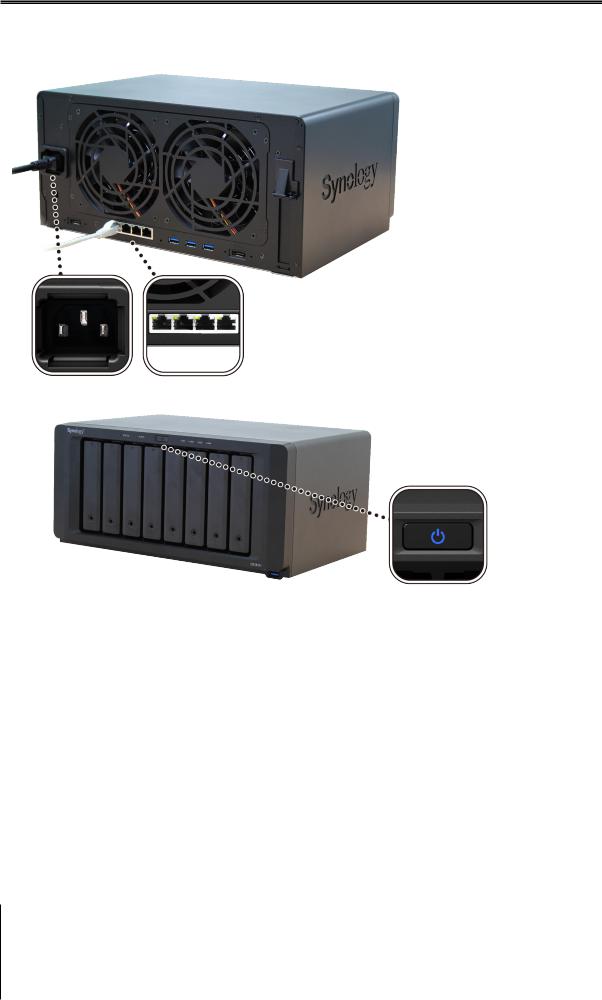
Start Up Your DiskStation
1Use the LAN cable to connect the DiskStation to your switch, router or hub.
2Connect the AC adapter to the power port of the DiskStation. Connect one end of the AC power cord to the AC power adapter, and the other to the power outlet.
3 Press the power button.
Congratulations! Your DiskStation is now online and detectable from a network computer.
9 Chapter 2: Hardware Setup
Loading...