

Page 1
VISION WPB
Utilisateur - User - Benutzer
Sulky Burel
BP 92111 - rue Fabien Burel
35221 Châteaubourg Cedex- FRANCE
Tél: 02.99.00.84.84 - Fax: 02.99.62.39.38
Site Internet : www.sulky-burel.com
e-mail : info@sulky-burel.com
A LIRE ATTENTIVEMENT AVANT D’UTILISER LE BOITIER
PLEASE READ CAREFULLY BEFORE USING THE CONTROL BOX
VOR GEBRAUCH DES ELEKTRONIKGERÄTS SORGFÄLTIG LESEN
Réf: 400 179 - FR-GB-DE/DIS/D-03
Page 2
2
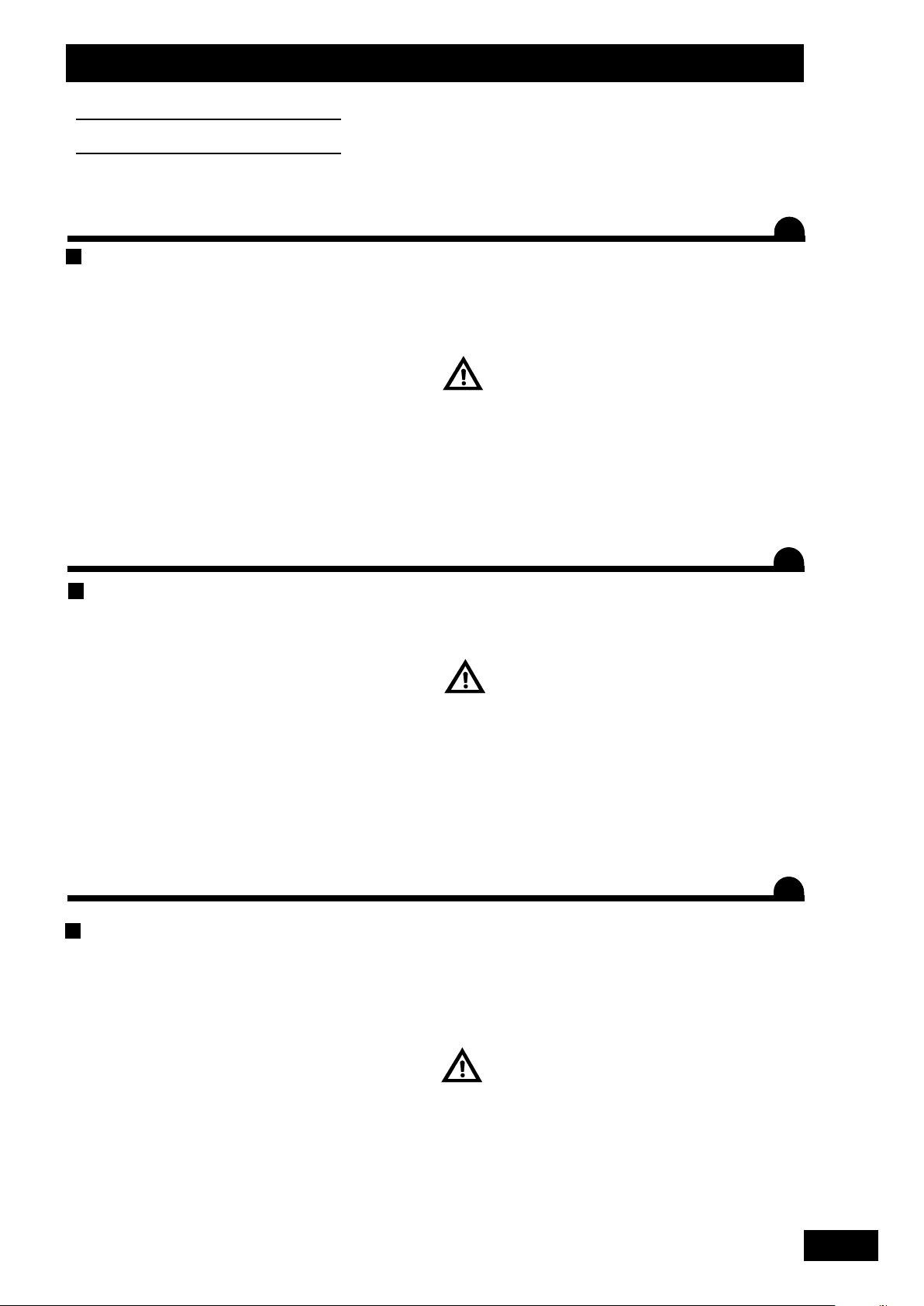
• Respecter les instructions de cette notice.
• Respecter les instructions du manuel d’utilisation du DPX correspondant.
• Ne jamais quitter le poste de conduite lorsque le tracteur est en marche.
• Réaliser les réglages du DPX VISION tracteur à l’arrêt.
• Assurez-vous qu’il n’y ait personne autour de la machine avant d’effectuer l’étalonnage du VISION.
• Ces symboles sont utilisés dans cette notice chaque fois que des recommandations concernent votre sécurité, celle
d’autrui ou le bon fonctionnement de la machine.
• Transmettez impérativement ces recommandations à tout utilisateur de la machine.
Risque d’accident Risque d’endommager
la machine
Faciliter le travail
Consignes de sécurité
Safety instructions
Sicherheitsvorschriften
• Follow the instructions contained in this manual.
• Follow the DPX User Manual recommendations.
• Never leave the driver’s position whilst the tractor is running.
• Carry out Vision DPX adjustments with the tractor stopped.
• Make sure no one is near the machine before calibrating the VISION unit.
• These symbols are used in these instructions every time recommendations are provided concerning your safety, the
safety of others or the correct operation of the machine.
• These recommendations must be given to all users of the machine.
Risk of accident Risk of damage
to the machine
Operating tip
• Die Anweisungen dieser Anleitung einhalten.
• Die Anweisungen des Benutzerhandbuchs des entsprechenden DPX einhalten.
• Den Führerstand niemals bei laufendem Schleppermotor verlassen.
• Einstellungen des DPX VISION bei ausgestelltem Schlepper vornehmen.
• Darauf achten, dass sich beim Kalibrieren des VISION niemand im Maschinenbereich aufhält.
• Diese Symbole werden in dieser Anleitung jedes Mal dann benutzt, wenn Empfehlungen für Ihre und anderer Personen
Sicherheit oder den einwandfreien Betrieb der Maschine gegeben werden.
• Es ist unerlässlich, diese Empfehlungen an alle Benutzer der Maschine weiterzugeben.
Unfallgefahr Gefahr, die Maschine
zu beschädigen
Arbeitserleichterung
FR
GB
DE
Page 3

3
Pages
PRESENTATION
SSOOMMMMAAIIRREE
Français
6-7
8-9
10-11
12-13
14-19
• A Présentation du système Vision
• B Connexion au tracteur
• C Mise en place du capteur vitesse
• D Boîtier de commande Vision
• E Présentation des fonctions
Pages PROGRAMMATION
20-23
24-31
32-33
34-35
36-37
38-39
• A Calibrage de la vitesse d'avancement
• B Réglage du débit
• C Choix de l’engrais
• D Sélection de la largeur de travail
• E Fonctions Tribord
• F Fonctions complémentaires
Pages
40-41
42-43
44-45
• Français
• Anglais
• Allemand
Lire attentivement la notice avant l’utilisation. Comprendre son
boîtier électronique c’est mieux l’utiliser. En français suivre le symbole.
Pages INFORMATIONS
46-47
48-49
50-51
52-53
54-56
• A Enregistrement des données
• B Modulation automatique
• C Diagnostique
• D Maintenance
• E Pannes/Remèdes
MISE EN ROUTE
3
4
1
2
FR
Page 4

• A Drive rate calibration
• B Output flow rate adjustment
• C Selecting the fertilizer
• D Selecting the working width
• E Tribord functions
• F Additional functions
4
CONTENTS
Read the operator's manual carefully before use. Understanding your electronic unit
will help you make better use of it. English instructions: follow this
symbol.
English
Pages
PRESENTATION
6-7
8-9
10-11
12-13
14-19
• A Presentation of the VISION system
• B Tractor interface connections
• C Setting up the rate sensor
• D VISION control unit
• E Functions
Pages PROGRAMMING
20-23
24-31
32-33
34-35
36-37
38-39
Pages
40-41
42-43
44-45
• French
• English
• German
Pages INFORMATIONS
46-47
48-49
50-51
52-53
54-56
• A Saving data
• B Automatic modulation
• C Diagnosis
• D Maintenance
• E Faults/Solutions
START-UP
GB
Page 5

• A Kalibrieren der Fahrgeschwindigkeit
• B Streumengeneinstellung
• C Wahl des Düngers
• D Wahl der Arbeitsbreite
• E Tribord-Funktionen
• F Zusatzfunktionen
55
IINNHHAALLTTSSVVEERRZZEEIICCHHNNIISS
Deutsch
Anleitung vor Benutzung sorgfältig durchlesen. Das Elektronikgerät richtig zu
verstehen, heißt, es besser (aus)nutzen zu können. Die deutsche Fassung ist
mit gekennzeichnet.
Seite
BESCHREIBUNG
6-7
8-9
10-11
12-13
14-19
• A Beschreibung des Systems Vision
• B Schlepperanschluss
• C Anbringen des Geschwindigkeitssensors
• D Bordcomputer VISION
• E Funktionsbeschreibungen
Seite
PROGRAMMIERUNG
20-23
24-31
32-33
34-35
36-37
38-39
Seite
40-41
42-43
44-45
• Französisch
• Englisch
• Deutsch
Seite
INFORMATIONEN
46-47
48-49
50-51
52-53
54-56
• A Speichern der Daten
• B Automatische Modulation/Veränderung
• C Diagnose
• D Wartung
• E Störungen/ Störungsbeseitigung
INBETRIEBSETZUNG
1
2
3
4
DE
Page 6
6
Présentation
Presentation
Beschreibung
A
5
7
8
6
4
1
❍
+
❍
-
2
3
9
Page 7
7
FR
GB
DE
Présentation
Presentation
Beschreibung
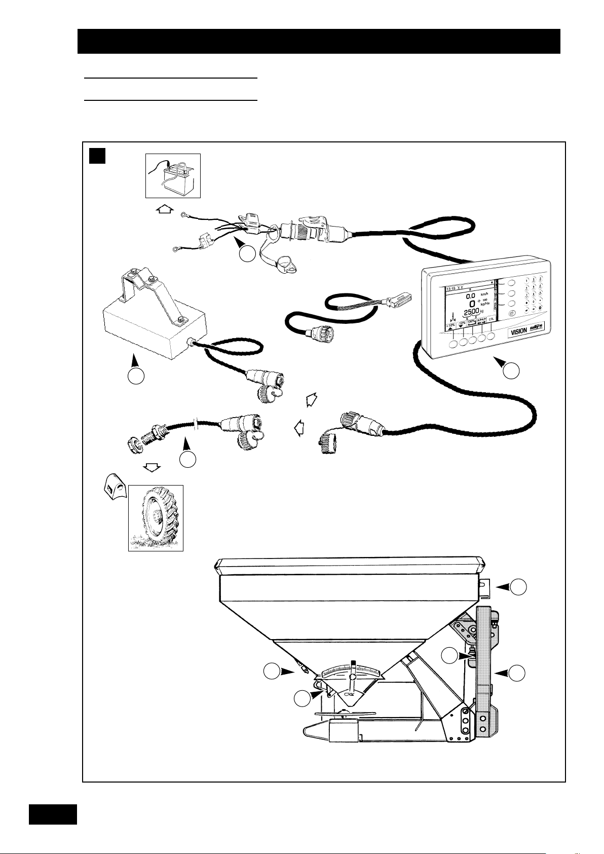
Présentation du système VISION
a)
Introduction
• Le Système VISION est un instrument de mesure et de
contrôle de l'épandage d'engrais granulés avec pesée
continue.
• Les informations de poids données par le VISION ne
peuvent pas être utilisées pour des transactions
commerciales.
• Le distributeur VISION ne doit être utilisé que pour les
travaux pour lesquels il a été conçu.
En cas de dommage lié à l’utilisation hors du cadre des
applications spécifiées par le constructeur, la responsabilité de
celui-ci sera entièrement dégagée.
• Le distributeur VISION ne doit être utilisé, entretenu et
réparé que par des personnes compétentes, familiarisées
avec les caractéristiques et le mode d’utilisation de la
machine.
b)
Présentation
Boîtier VISION WPB
Faisceau d’alimentation 12 V. (option)
Capteur de vitesse d'avancement ou raccordement radar.
Capteur ouverture / fermeture des trappes.
Boîte de connexion.
Vérin électrique de contrôle du débit.
Châssis attelage relié par 4 lames souples au bâti
du distributeur.
Capteur inox de pesée.
Kit radar.
A
1
2
3
4
5
6
7
8
Presentation of the VISION system
a)
Introduction
• The Vision system is a measuring and monitoring instrument
for granular fertiliser spreading with continuous weighing.
• The weight data produced by Vision cannot be used for
commercial transactions.
• The VISION spreader must be used exclusively for those
applications it was designed for.
In the event of damage due to operation outside of the scope
of applications specified by the Manufacturer, the
manufacturer’s liability shall be fully relieved.
• The Vision spreader must be used, maintained and repaired
only by competent personnel familiar with the specifications
and use of the machine.
b)
Presentation
VISION WPB unit.
12-volt supply bundle. (optional)
Drive rate sensor or radar interface.
Shutter Open/Close sensor.
Connection box.
Flow rate control electric ram.
Châssis Hitching frame connected to the spreader frame by 4
flexible blades.
Weighing stainless steel sensor.
A
1
2
3
4
5
6
7
8
Beschreibung des Systems VISION
a)
Einführung
• Das System VISION ist ein Gerät zur Messung und Kontrolle
bei der Streuung von Düngergranulat mit kontinuierlichem
Abwiegen.
• Die vom VISION gelieferten Gewichtsinformationen dürfen
nicht für Handelsgeschäfte benutzt werden.
• Der Düngerstreuer VISION darf nur für die Arbeiten eingesetzt werden, für die er konzipiert ist.
Für den Fall, dass Beschädigungen bei einer Benutzung auftreten, die außerhalb des Rahmens der vom Hersteller spezifizierten Anwendungen liegt, ist letzterer von jeglicher Haftung befreit.
• Der Düngerstreuer VISION darf nur von kompetenten
Personen, die sich mit seinen Eigenschaften und der
Betriebsanleitung vertraut gemacht haben, benutzt, gewartet
und repariert werden.
b)
Beschreibung
Der Bordcomputer VISION WPB.
Stromversorgungskabel. (Sonderausrüstung)
Fahrgeschwindigkeitssensor oder Radarverbindung.
Sensor Öffnen/ Schließen der Schieber.
Verteilerkasten.
Elektro-Zylinder zur Streumengenkontrolle.
Kupplungsrahmen, der mit 4 Blattfedern an den Rahmen des
Streuers verbunden ist.
Wiegesensor aus Edelstahl.
A
1
2
3
4
5
6
7
8
9
1
1
Page 8
8
Présentation
Presentation
Beschreibung
B
237 mm
75 mm
142 mm
❍
+
❍
-
Page 9
9
FR
GB
DE
Présentation
Presentation
Beschreibung
Connexion au tracteur
a)
Attelage
• Le DPX VISION est équipé d’un attelage 3 points catégorie
II. La position du DPX est horizontale au travail.
• Monter la transmission en vérifiant que sa longueur
correspond bien au tracteur. Le régime de la PDF
est de 540 tr/mn. (ou option 1000tr/mn pour le Magnum)
• Brancher l’hydraulique d’ouverture et de fermeture
des trappes.
b)
Installation du VISION
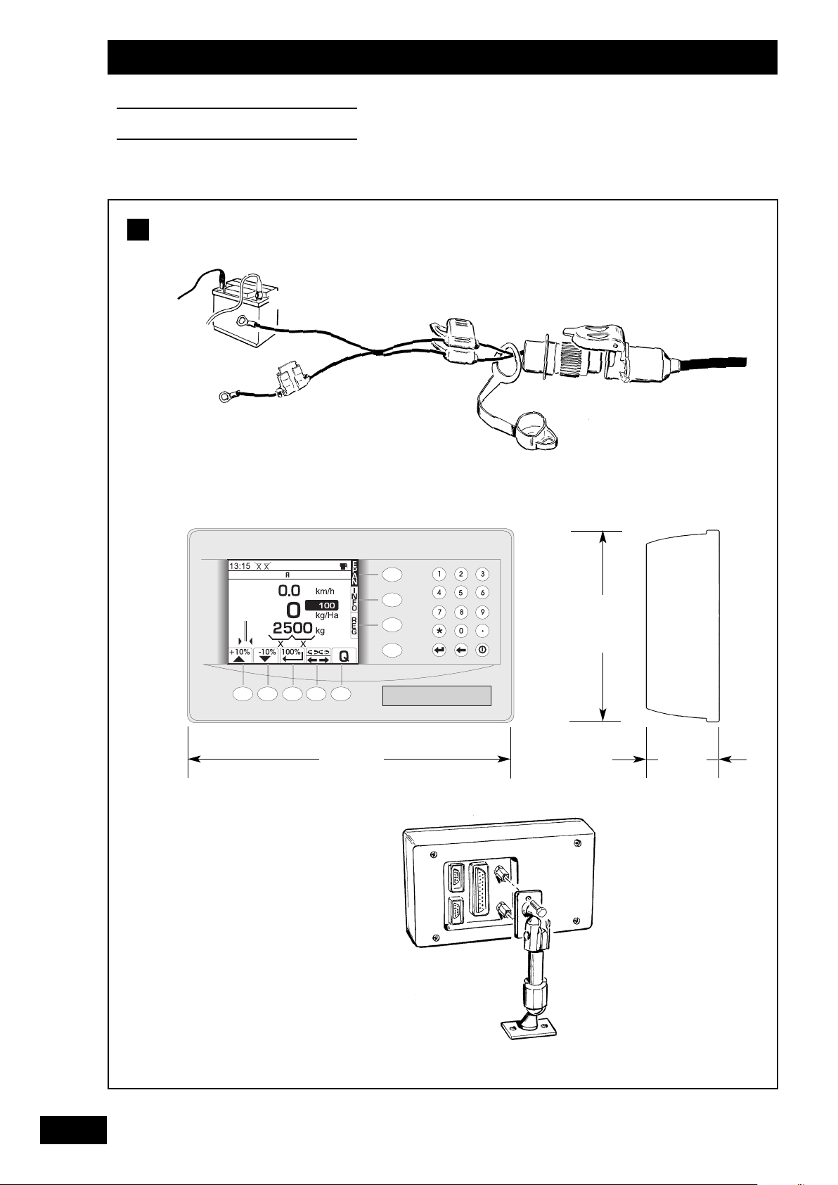
• Il est impératif de brancher l’alimentation électrique
du boîtier directement à la batterie 12 volts du tracteur.
• Lorsque la prise est branchée, le boîtier peut être allumé.
• Le boîtier VISION possède un accumulateur permettant
de garder en mémoire les données programmées.
• Le boîtier VISION doit être est protégé par des fusibles 5 A
sur son alimentation.
Faisceau d’alimentation disponible en option.
• Le boîtier doit être monté de manière à ce qu’il soit
bien visible par le conducteur.
ATTENTION
• Ne pas poser brusquement l’attelage en pleine charge sur le
sol.
• Ne pas dépasser la charge maximale :
- 4 000 kg sur le DPX MAGNUM
- 2 400 kg sur le DPX EXPERT
• Bien remettre les bouchons de protection sur les câbles
de connexion.
• Vérifier que le cardan PDF soit à la bonne longueur
et ne touche pas le châssis.
B
Tractor interface connections
a)
Hitching
• The VISION DPX is fitted with a 3-point, category II hitching
hook. The DPX is in horizontal position.
• Fit the drive shaft while ensuring the its length matches the
tractor. PDF rate is 540 RPM. (1000 rpm option on
Magnum)
• Connect the shutter control hydraulic system.
b)
Installing VISION
• The unit power supply must be connected directly to the
12-volt battery of the tractor.
• Once the plug has been connected, the unit can be turned
on.
• The VISION unit features a buffer battery which enables it
to keep programmed data and settings in memory.
• The VISION unit is protected by 5-Amp fuses.
Optional power bundle available.
• The unit must be sited so as to be clearly visible to the driver.
CAUTION!
• Do not drop the hitch to the ground when loaded.
• Do not exceed the maximum payload:
- 4000 kg on DPX MAGNUM
- 2400 kg on DPX EXPERT
• Make sure to replace all protective plugs and covers on
connecting cables.
• Make sure the PDF universal joint length is correct and that the
shaft is not in contact with the chassis.
B
Schlepperanschluss
a)
Ankupplung
• Der DPX VISION ist mit einer Dreipunktkupplung der Klasse
2 ausgerüstet. Der Streuer muss sich in waagrechter
Stellung befinden.
• Die Antriebswelle einbauen, wobei überprüft werden muss,
dass ihre Länge zum Schlepper passt. Die Zapfwellendrehzahl liegt bei 540 U/min. (oder, als Option für den
Magnum, bei 1000 U/min.)
• Die Hydraulik zum Öffnen und Schließen der Schieber
anschließen.
b)
Installierung des VISION
• Es ist notwendig, die Stromversorgung des Bordcomputers
direkt an die 12V-Batterie des Schleppers anzuschließen.
• Sobald der Stecker angeschlossen ist, kann der Bordcomputer angeschaltet werden.
• Der Bordcomputer VISION verfügt über einen
Akkumulator, der die programmierten Daten speichert.
• Die Stromversorgung des VISION-Elektronikgerät durch 5 ASicherungen schützen.
Versorgungskabelbündel als Option lieferbar.
• Der Computer muss so installiert sein, dass er gut vom Fahrer
gesehen und abgelesen werden kann.
ACHTUNG
• Den voll beladenen Anbau nicht plötzlich auf dem Boden
abstellen.
• Das Höchstladegewicht nicht überschreiten:
- 4 000 kg für den DPX MAGNUM
- 2 400 kg für den DPX EXPERT
• Die Schutzstöpsel müssen wieder richtig auf die Verbindungskabel aufgesteckt werden.
• Überprüfen Sie, dass die Gelenkwelle für den Zapfwellenantrieb
die richtige Länge hat und den Rahmen nicht berührt.
B
Page 10
10
Présentation
Presentation
Beschreibung
20mm
(min)
5 - 10mm
a)
b)
c)
1
2
d)
C
Page 11

11
FR
GB
DE
Présentation
Presentation
Beschreibung
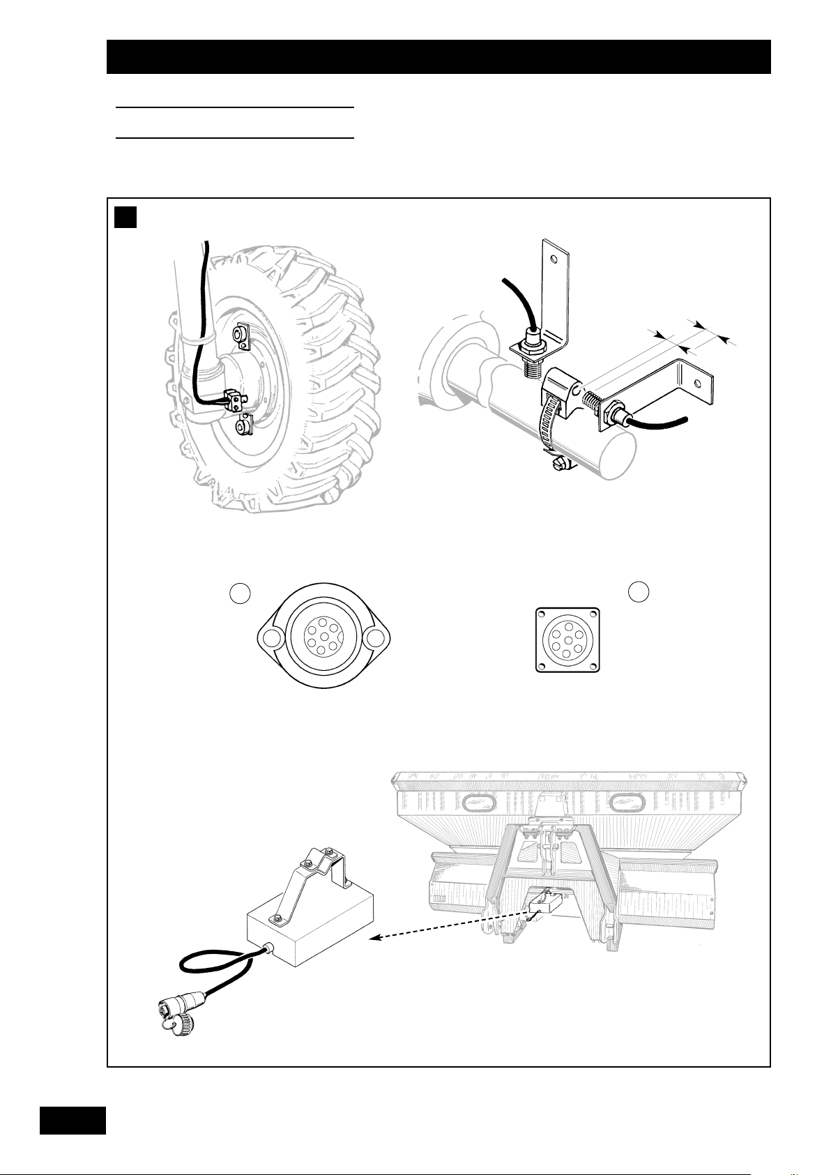
Mise en place du capteur de vitesse
L’information vitesse peut être réalisée soit :
• par la roue du tracteur,
• par l’arbre de transmission du pont avant d’un tracteur 4x4,
• par information radar pour les tracteurs pré-équipés et
compatibles.
a)
Par la roue du tracteur
• Pour un montage sur roue de grand diamètre, favoriser
l’adaptation avec plusieurs aimants par souci de précision.
• Prévoir un minimum de 8 aimants par roue arrière du
tracteur.
b)
Par l’arbre de transmission du pont avant
• Pour le montage du capteur, suivre les instructions.
• Ce montage est probablement un des plus précis car
l’arbre à une forte démultiplication par rapport à la vitesse
d’avancement.
c)
Par information radar
• L’adaptation est possible s’il y a une prise radar en cabine.
Voir information complémentaire avec votre revendeur
tracteur.
Exemple :
Fendt, John deere,
Massey-fergusson (Datatronic 1).
d)
Radar Sulky
• Raccorder le radar à la prise du boîtier
prévue
à cet effet.
C
1
2
Setting up the rate sensor
The drive rate data can come from either:
• a tractor wheel,
• the front axle drive shaft of a 4x4 tractor,
• radar on pre-equipped and compatible tractors.
a)
tractor wheel
• When mounted on large-diameter wheels, it is preferable
to use the several-magnet adaptor system, for greater
accuracy.
• Use at least 8 magnets per tractor wheel (rear).
b)
Front axle drive shaft
• Follow instructions for mounting the sensor.
• This mounting option is probably the most accurate
because of the high reduction ratio of the shaft in relation
to the drive rate.
c)
Radar information
• Adaptation is possible if there is a radar connector in the
cab. See additional data with your tractor dealer.
Example:
Fendt, John deere,
Massey-fergusson (Datatronic 1).
d)
Sulky radar
• Connect the radar to the socket provided for that purpose
on the unit.
C
Anbringen des Geschwindigkeitssensors
Die Information über die Geschwindigkeit kann auf mehrere
Arten ermittelt werden:
• Über das Schlepperrad,
• Über die Antriebswelle des Vorderradantriebs eines AllradSchleppers,
• Über Radarinformation für die schon ausgerüsteten und
kompatiblen Schlepper.
a)
Über das Schlepperrad
• Bei Montage auf ein Rad mit großem Durchmesser sollten
aus Gründen der Präzision mehrer Magnete verwendet
werden.
• Pro Schlepperhinterrad mindestens 8 Magnete vorsehen.
b)
Über die Antriebswelle des Vorderradantriebs
• Für den Einbau des Sensors die Anweisungen befolgen.
• Diese Installierung ist wahrscheinlich die genaueste, da die
Welle eine starke Untersetzung im Verhältnis zur Fahrgeschwindigkeit hat.
c)
Über Radarinformation
• Das System ist anpassbar, wenn in der Schlepperkabine ein
Radaranschluss vorhanden ist. Weitere Informationen kann
Ihnen Ihr Schlepper-Verkäufer geben.
Zum Beispiel:
Fendt, John deere,
Massey-fergusson (Datatronic 1).
d)
Mit dem Sulky-Radar
• Den Radar an der dafür vorgesehenen Anschlussstelle am
Computer anschließen.
C
1
2
1
2
Page 12
12
Présentation
Presentation
Beschreibung
D
Page 13
13
FR
GB
DE
Présentation
Presentation
Beschreibung
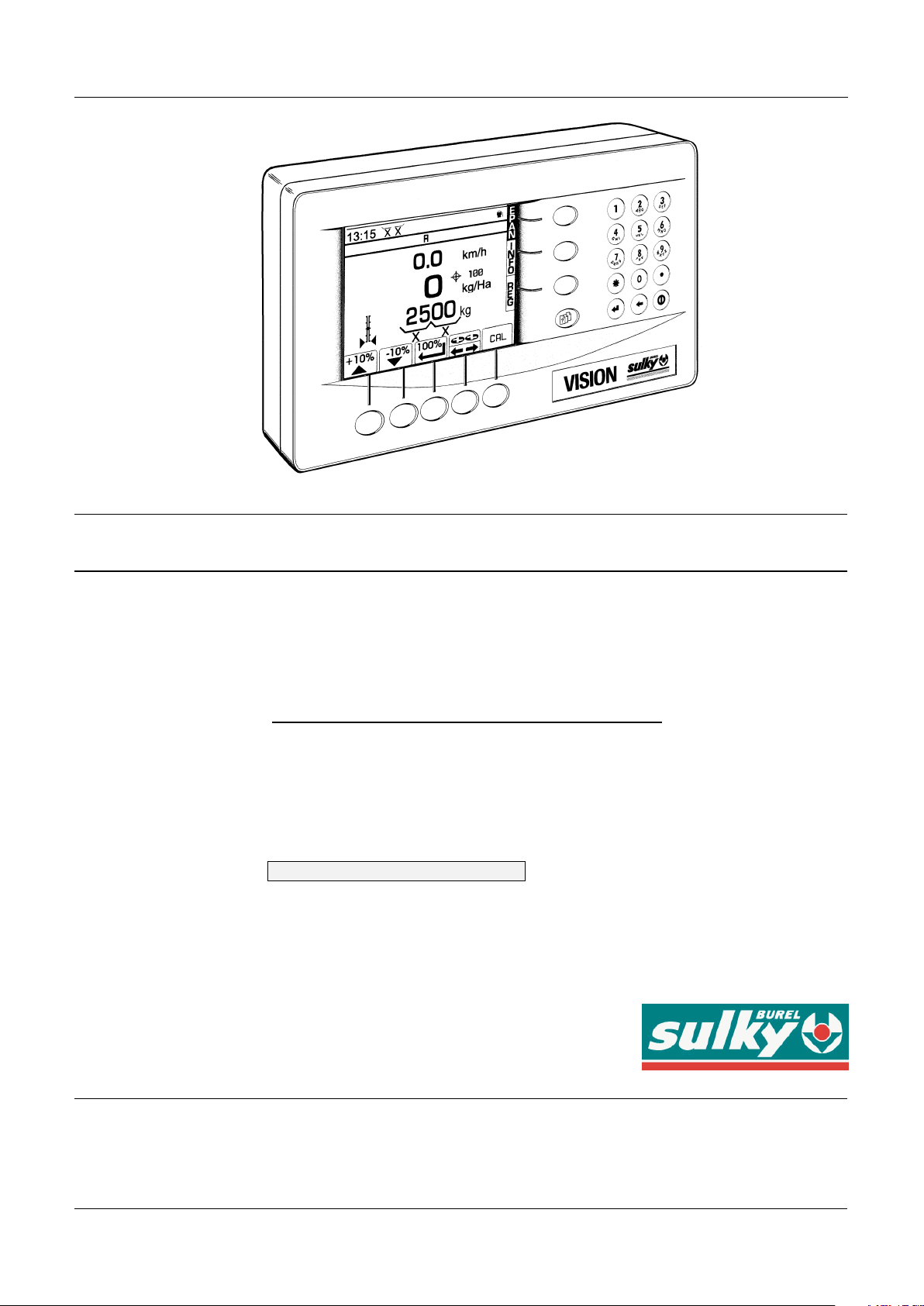
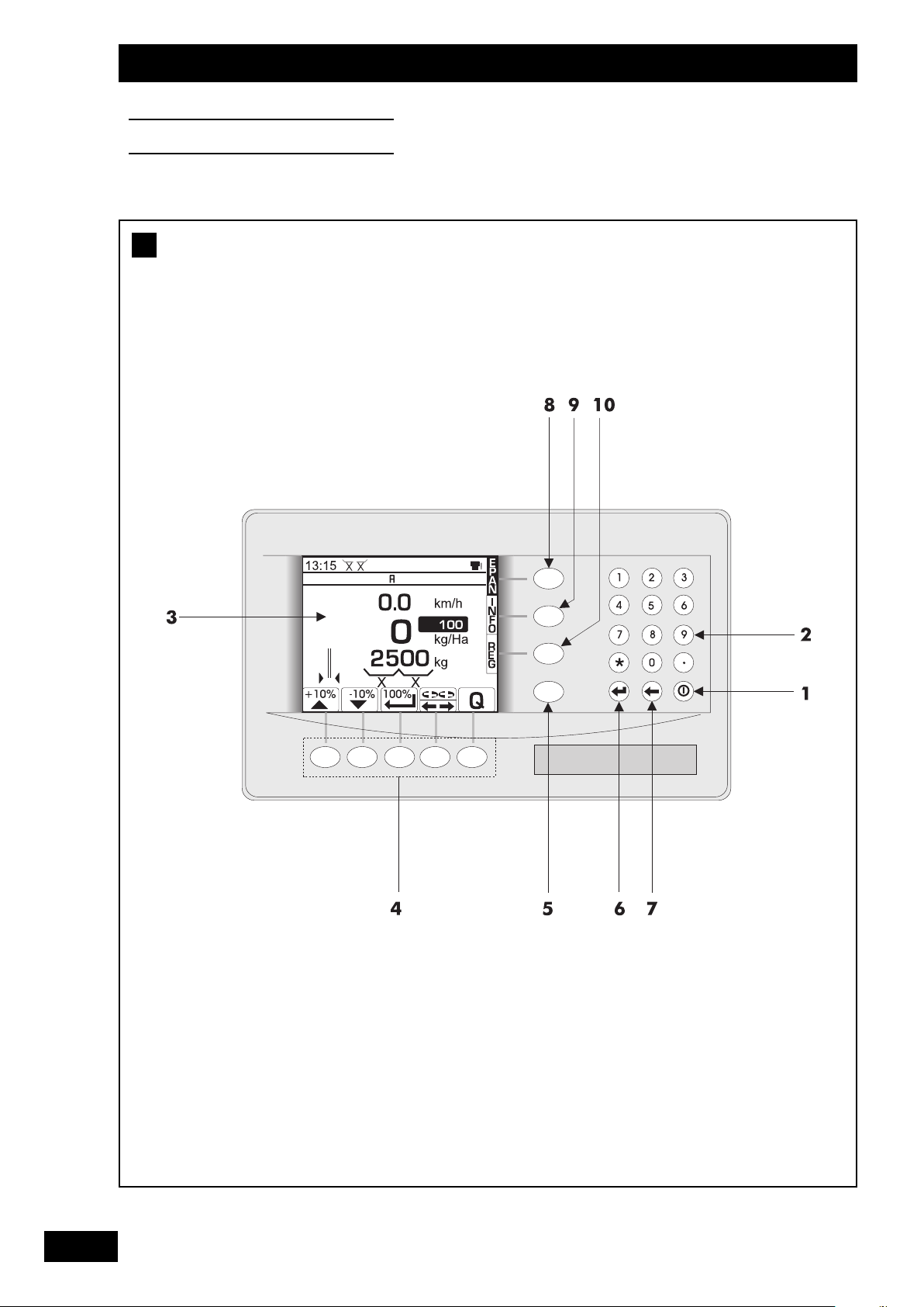
Boîtier de commande VISION
Mise sous tension
Pavé numérique et alphabétique
Ecran multifonction
Touches des fonctions
Touche menu paramétrage usine
et diagnostique revendeur
Touche de “confirmation” ou “entrée” d’un paramétrage
Touche “retour”
Touche “menu épandage” : utilisée en cours d’épandage
Touche “menu information” : utilisée en consultation
Touche “menu réglage” : utilisée en début d’épandage
• Le boîtier fonctionne sous la forme d’un menu défilant.
• Prendre le temps de lire les informations.
D
1
2
3
4
7
8
9
10
5
6
VISION control unit
Power up
Alpha-numeric pad
Multifunction screen
Function keys
Factory settings and diagnostic key
Settings confirmation or ENTER key
“Backspace” key
“Spreading menu” key: to be used during spreading
operations
“Info menu ” key: used for diagnosis or monitoring
“Settings menu” key: for use when beginning to spread
• The unit operates according to a scroll-down menu.
• Take time to read all the data and info.
D
Bordcomputer VISION
Unterspannungsetzen
Zahlentastenfeld
Multifunktioneller Bildschirm
Funktionstasten
Taste des Menüs Werksparametrierung und Diagnose des
Verkäufers
„Bestätigungs“-Taste oder „Eingabe“ einer Parametrierung
„Zurück“-Taste
Taste „Streu-Menü“: wird beim Streuen benutzt
Taste „Informations-Menü“: wird bei Anfragen benutzt
Taste „Einstellungs-Menü“: wird zu Beginn des Streuens
benutzt
• Das Gerät funktioniert mit ablaufenden Menüs.
• Nehmen Sie sich die Zeit, die angezeigten Informationen
zu lesen.
D
1
2
3
4
7
8
9
10
5
6
1
2
3
4
7
8
9
10
5
6
Page 14
14
Présentation
Presentation
Beschreibung
E
a)
Page 15
-10% modulation key
Restoration of the reference dose/hectare following
modulation.
Tribord control key and “right” or “left” modulation select
key
Output flow rate test key
Hydraulic shutter close/open indicator
Weight in the hopper (effective)
Dose per hectare targetted
Alarm
Correction mode info: Static or Dynamic
Name of fertiliser
Modulationstaste - 10%
Zurück zur Referenzstreumenge/ha nach einer Modulation.
Steuertaste für Tribord und für die Auswahl zwischen
"rechts" und "links".
Taste Streumengentest
Anzeige Öffnung/ Schließung der Hydraulikschieber
Gewichtskontrolle des Düngers im Behälter (Reell)
Gewünschte Streumenge/ ha
Alarm
Information über den Korrektur-Modus: dynamisch oder
statisch
Düngerbezeichnung
15
FR
GB
DE
Présentation
Presentation
Beschreibung
Présentation des fonctions
a) Menu épandage
• Le menu épandage est utilisé en cours de travail.
Vous disposez des principales informations de contrôle.
Heure
Vitesse d’avancement. Elle peut être légèrement
différente du compteur tracteur.
Quantité d’épandage.
Indicateur de positionnement des vérins électriques de
contrôle des débits.
Touche modulation + 10%
Touche modulation - 10%
Retour à la dose hectare de référence après une modulation.
Touche commande TRIBORD et de sélection modulation
“droite” ou “gauche”
Touche test de débit
Indicateur d’ouverture/fermeture des trappes hydrauliques
Poids dans la trémie (Réel)
Dose hectare souhaitée
Alarme
Information mode de correction : dynamique ou statique
Nom de l’engrais
E
1
2
3
4
7
8
9
10
11
12
13
14
15
5
6
Functions
a) Spreading menu
• The spreading menu is used during spreading operations. It
gives you the main controlling data:
Time
Working speed. It may be slightly different from that on
the tractor speedometer.
Spreading amount.
Position indicator of the flow-rate control electrical rams.
+10% modulation key
E
Funktionsbeschreibungen
a) Streu-Menü
• Das Streu-Menü wird während der Arbeit benutzt.
Sie verfügen über die wesentlichsten Informationen zur
Kontrolle.
Uhrzeit
Fahrgeschwindigkeit. Diese kann geringfügig von der des
Geschwindigkeitsmessers des Schleppers abweichen.
Streumenge.
Stellungsanzeiger der Elektro-Zylinder zur
Streumengenkontrolle.
Modulationstaste + 10%
E
1
2
3
4
7
8
9
10
11
12
13
14
15
5
6
1
2
3
4
7
8
9
10
11
12
13
14
15
5
6
Page 16
16
Présentation
Presentation
Beschreibung
E
b)
Page 17

17
FR
GB
DE
Présentation
Presentation
Beschreibung
Présentation des fonctions`
b) Menu informations
• Le menu information est utilisé en consultation pour
connaître les performances du chantier d’épandage.
Nombre de tonnes épandues. (Théorique)
Surface en hectare épandue. (Réelle)
Indicateur du nombre d’hectares ou nombre de mètres
restant à épandre.
Touche de sélection en information partielle
pour la parcelle ou totale pour le chantier d’épandage.
Touche de sélection du nombre d’hectares ou du nombre de
mètres restant à épandre avec la quantité restant en trémie.
Touche de sélection de la fonction enregistrement
des données et mode DGPS.
Touche d’information des alarmes actives.
Touche de remise à zéro des compteurs hectare et tonnage.
E
1
2
3
4
7
8
5
6
Functions`
b) Info menu
• The info menu is used to monitor spreading data and
performance.
Number of tonnes spread. (theoretical)
Area spread (in hectares). (effective)
Area remaining to be spread (in hectares or in square
metres).
Selection key for partial (plot) or overall (site) spreading
data.
Selection key for the number of hectares or metres
remaining to be spread and the amount left in the hopper.
Selection key for data saving or GPS functions.
Active alarm info key.
Area and tonnage counter reset key.
E
Funktionsbeschreibungen`
b) Informations-Menü
• Das Informations-Menü wird benutzt, um die geleistete
Streuarbeit in Erfahrung zu bringen.
Anzahl der gestreuten Tonnen. (Theoretisch)
Bestreute Fläche in Hektar. (Reell)
Anzeige der noch zu bestreuenden Fläche in Hektar oder
Meter.
Wahltaste: Teilinformation über die Parzelle oder Gesamt-
information über den Streueinsatz.
Wahltaste: mit der im Düngerbehälter verbleibenden Restmenge noch zu bestreuende Fläche in Hektar oder Meter.
Wahltaste: Datenspeicherung oder DGPS-Modus.
Informationstaste: aktivierte Alarmfunktionen.
Taste zur Nullstellung von Hektar- und Mengenzähler.
E
1
2
3
4
7
8
5
6
1
2
3
4
7
8
5
6
Page 18
18
Présentation
Presentation
Beschreibung
E
c)
Page 19

Functions`
c) Settings menu
• The settings menu is used to start-up the VISION DPX,
either to save final data or to save spreading real-time data.
Unit settings:
1- Time settings
2- Screen brightness settings
3- Measurement units settings
4- Display Language settings
5- Coordinates.
6- Select instrument (spreader or seed drill).
Drive rate calibration keys
Funktionsbeschreibungen`
c) Menü Einstellung
• Das Einstellungs-Menü wird bei Inbetriebnahme des DPX
VISION benutzt, entweder zum Speichern der endgültigen
Daten, oder zum Speichern der zum Streuen gehörenden
Daten.
Daten zur Einstellung des Bordcomputers:
1- Einstellung der Uhrzeit
2- Einstellung der Bildschirmhelligkeit
3- Einstellung der Maßeinheiten
4- Einstellung der auf dem Bildschirm benutzten Sprache
5- Koordinaten
6- Wahl Maschine (Düngerstreuer oder Drillmaschine).
Kalibriertaste für die Fahrgeschwindigkeit
19
FR
GB
DE
Présentation
Presentation
Beschreibung
Présentation des fonctions`
c) Menu réglage
• Le menu réglage est utilisé à la mise en route du DPX
VISION. Soit pour l’enregistrement des données définitives,
soit
pour l’enregistrement des données propres à l’épandage.
Données réglage du boîtier :
1- Réglage de l’heure.
2- Réglage de la luminosité de l’écran.
3- Réglage des unités de mesure.
4- Réglage de la langue utilisée à l’écran.
5- Coordonnées.
6- Choix instrument (épandeur ou semoir).
Touche de calibrage de la vitesse d’avancement
Touche de sélection du mode de correction dynamique
ou statique et utilisation de la tare (mise à zéro).
Touche de sélection de l’engrais, mise en mémoire
(8 niveaux), et inscription du “Facteur T” propre
à chaque engrais.
• Inscription du nom de l’engrais avec .
• Calibrage spécifique avec .
Touche de sélection de simulation de vitesse
pour le remplacement du mode DPA (mode DPM).
Touche de sélection de la largueur de travail
pour le calcul de toutes les informations du boîtier.
E
1
2
3
4
5
6
Selection key for dynamic or static correction mode and
use of the tare (resetting).
Fertiliser selection key, saving (8 levels) and recording of
the T factor specific to each fertiliser.
• Recording fertiliser name with .
• Specific calibration with
.
Rate simulation selector key for DPA mode change
(DPM mode).
Working width selection key for computation of all unit
data.
E
1
2
3
4
5
6
Wahltaste: dynamischer oder statischer Korrigiermodus
und Benutzung der Tara (Nullstellung).
Wahltaste Dünger, Abspeichern (8 Stufen) und Eingabe
des für jeden Dünger spezifischen „Faktors T“.
• Eingabe der Düngerbezeichnung über die Taste .
• Spezifische Kalibrierung über die Taste .
Wahltaste für die Geschwindigkeitssimulation wenn nicht
im DPA-Modus gearbeitet wird (DPM-Modus).
Wahltaste für die Arbeitsbreite zur Berechnung aller
Informationen des Bordcomputers.
E
1
2
3
4
5
6
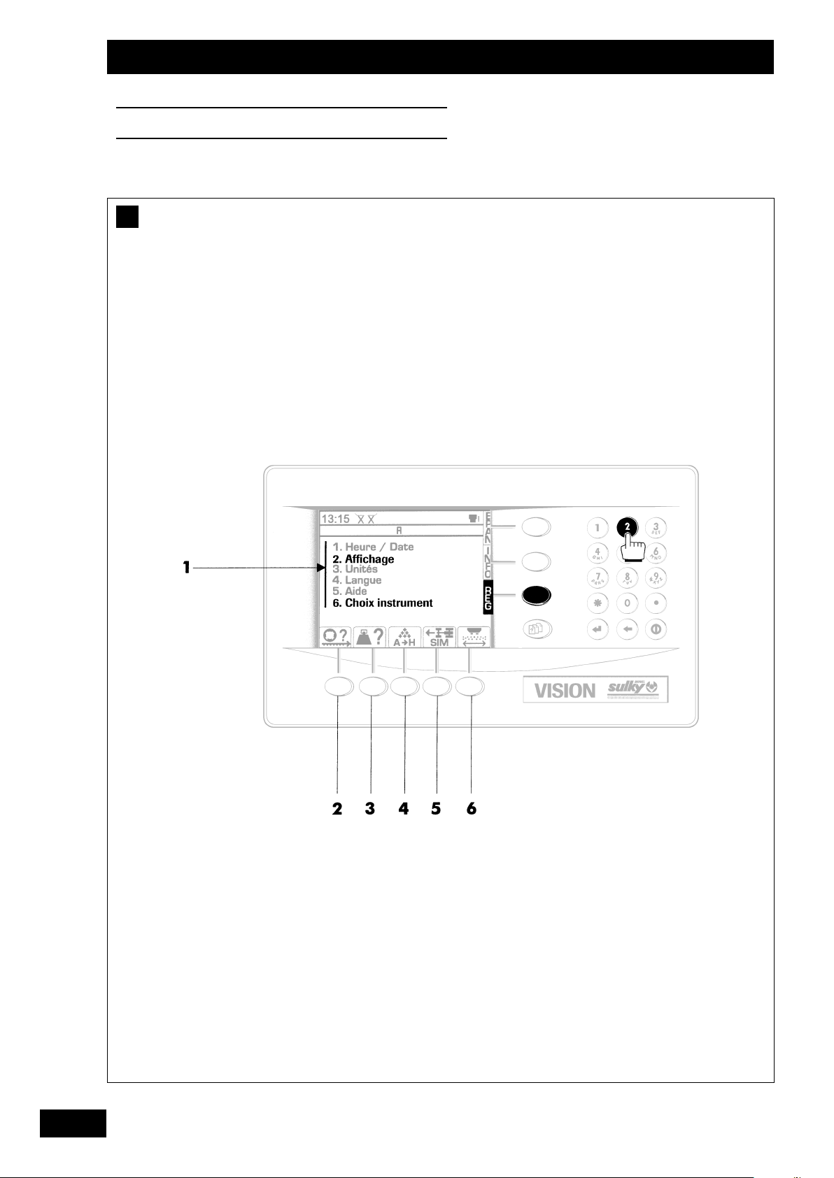
Page 20

20
Programmation
Programming
Programmierung
A
6. Choix instrument
a)
Page 21

21
FR
GB
DE
Programmation
Programming
Programmierung
Calibrage de la vitesse d’avancement
Sélectionner le menu REG.
a) Capteur de vitesse
• Jalonner 100 mètres.
• Placer le tracteur au premier jalon.
• Sélectionner la fonction .
• Choisir le type de capteur avec .
1
er
tracteur - 2etracteur -3etracteur - 4etracteur
• Sélectionner devant le 1
er
jalon.
• Sélectionner “Calibrage sur 100m”.
• Se placer devant le premier jalon.
• Presser pour activer.
• Avancer jusqu'au 2
ème
jalon, espacé d'une distance de 100 m.
• Après arrêt au 2ème jalon. Presser pour valider
• Votre calibrage de vitesse est
effectué.
Le VISION a calculé un cœfficient propre au tracteur et le
garde en mémoire.
b) Capteur de radar
• Procéder de la même manière en effectuant un test sur
100 m.
• La valeur d'impulsion/mètre avec un radar est beaucoup
plus faible qu'avec un capteur de vitesse standard.
Remarques :
• Le cœfficient de vitesse est toujours inférieur à 1.
• Le cœfficient de vitesse peut être modifié manuellement :
- sélectionner
,
- sélectionner 2 et changer à l’aide du pavé numérique,
- sélectionner pour sortir.
• Il est impératif d'effectuer le test sur 100m à la mise en
route du VISION, pour remplacer les valeurs "par défaut"
du boîtier.
A
Drive rate calibration
Select the REG menu.
a) Rate sensor
• Peg mark 100 metres.
• Position the tractor to the 1st peg mark.
• Select function .
• Select the sensor type with .
1st tractor -2nd tractor - 3rd tractor - 4rd tractor
• Select
opposite the 1st peg mark.
• Select “100 m calibration”.
•
Position the tractor opposite the 1st peg mark.
• Press to activate.
• Move to the 2nd peg mark approximately 100 m away.
• After stopping opposite the 2nd peg mark, press to validate
• Rate calibration is complete.
VISION computed a coefficient specific for each tractor and
saved it in memory.
b) Radar sensor
• Carry out the same procedure en perform a test over
100 metres.
• The pulse/metre value is much with a radar than with a
standard rate sensor.
Notes:
• The rate coefficient is still below 1.
• The rate coefficient can be modified manually:
- select
,
- select 2 and modify with
the numeric pad,
- select
to exit.
• It is imperative to carry out the 100 m test when startingup VISION to replace the unit DEFAULT settings.
A
Kalibrieren der Fahrgeschwindigkeit
Das Menü REG anwählen.
a) Geschwindigkeitssensor
• 100 m markieren.
• Den Schlepper zur ersten Markierung bringen.
• Die Funktion wählen
• Den Sensortyp mit
wählen.
1. Schlepper - 2. Schlepper 3. Schlepper - 4. Schlepper
• Vor der ersten Markierung
wälen.
• „Kalibrieren auf 100 m“ anwählen.
• Sich vor die erste Markierung stellen.
• Zur Aktivierung drücken.
• Bis zur 2. Markierung fahren, die sich in einem Abstand
von 100 m befindet.
• An der 2. Markierung anhalten. Zur Bestätigung
drücken.
• Das Kalibrieren der Geschwindigkeit ist damit
abgeschlossen.
Der VISION hat nun einen auf den Schlepper angepassten
Koeffizienten berechnet und gespeichert.
b) Radarsensor
• Auf die gleiche Weise vorgehen, indem ein Test bei 100 m
vorgenommen wird.
• Bei Benutzung eines Radars ist der Wert Impuls/Meter
sehr viel geringer als bei Messung mit einem standardmäßigen Geschwindigkeitssensor.
Anmerkungen:
• Der Geschwindigkeitskoeffizient liegt immer unter 1.
• Er kann manuell verändert werden:
- wählen,
- 2 wählen und mithilfe des Nummernfeldes verändern,
- über die Taste beenden.
• Es ist unbedingt notwendig, bei der Inbetriebnahme des
VISION den Test auf 100 m durchzuführen, damit die
Standardwerte des Computers ersetzt werden.
A
1
2
Page 22

22
Programmation
Programming
Programmierung
A
c)
Page 23

23
FR
GB
DE
Programmation
Programming
Programmierung
Calibrage de la vitesse d’avancement
c) Simulation de vitesse d’avancement
La simulation de vitesse peut être utilisée :
- lorsqu’il y a un problème avec le capteur,
- pour simuler une ouverture de trappe,
- pour vider l’engrais du distributeur à poste fixe,
- pour utiliser le VISION sans DPA.
• Sélection de la fonction .
• Entrer la vitesse d’avancement avec le pavé numérique.
• Valider par pour commencer la simulation.
• Pour stopper la simulation :
- sélectionner et valider de nouveau.
Remarque : vous pouvez actionner la simulation de vitesse
d’avancement par le menu REGLAGE.
A
Kalibrieren der Fahrgeschwindigkeit
c) Simulieren der Fahrgeschwindigkeit
Die Geschwindigkeitssimulation kann eingesetzt werden:
- wenn ein Problem am Sensor auftritt,
- um eine Schieberöffnung zu simulieren,
- um den Dünger des Streuers an einem festen Ort zu
entleeren,
- um den VISION ohne DPA zu benutzen.
• Die Funktion wählen.
• Die Fahrgeschwindigkeit über das Nummernfeld eingeben.
• Mit bestätigen, damit die Simulation beginnen kann.
• Zum Beenden der Simulation:
- wählen und erneut mit bestätigen.
Anmerkung: Die Simulation der Fahrgeschwindigkeit kann
über das Menü Einstellung in Gang gesetzt werden.
A
Drive rate calibration
c) Drive rate simulation
The drive rate simulator can be used:
- when there is a problem with a sensor,
- to simulate a shutter opening,
- to empty the hopper fertiliser at a fixed location,
- To use VISION without DPA.
• Select function .
• Enter the drive rate with the numeric pad.
• Validate by to start simulation.
• To stop simulation:
- select and validate again with .
Note: It is possible to operate drive rate simulation from
the Settings menu.
A
Page 24

24
Programmation
Programming
Programmierung
B
a)
b)
6. Choix instrument
Page 25

25
FR
GB
DE
Programmation
Programming
Programmierung
Réglage du débit
Sélectionner le menu REG
Sélectionner la fonction .
a) Tare
Il est nécessaire d’effectuer une tare (mise à zéro du
peson) régulièrement par exemple après 3 ou 4
chargement.
• Sélectionner Tare
• Valider par pour remettre à zéro.
Remarque
La tare est obligatoirement à faire lorsque l’on ajoute
un équipement sur le distributeur ou lorsque en condition
très humide d’épandage, il y a de la boue sur la machine.
• Assurez-vous qu'il n’y ait plus d'engrais dans la trémie
avant de refaire une tare.
b) Essai de débit avec mode de correction
Pour le réglage du débit, il y a deux modes de correction :
statique et dynamique
• Sélectionner
• Choisir le mode Statique pour :
- une correction après 200 kg épandus,
- un test d’engrais inconnu (T inconnu),
- l’utilisation d’un ravitailleur.
• Choisir le mode Dynamique pour :
- une correction continue en cours d’épandage.
- un test d’engrais connu (test statique déjà réalisé).
- sélectionner
pour sortir.
B
Output flow rate adjustment
Select the REG menu
Select the function.
a) Tare
Tare has to be determined regularly (scales resetting), e.g.,
after 3 or 4 loadings.
• Select Tare
• Validate by to reset.
Note
Tare must be determined when new add-ons are fitted to the
spreader or under very wet spreading conditions if there is
mud on the machine.
• Make sure there is no fertilizer in the hopper before tare
determination.
b) Flow rate test with correction mode
To adjust flow rate, two correction modes are available: static
or dynamic
• Select
• Choose the Static mode for:
- corrections after 200 kg spread,
- testing an unknown fertiliser (T unknown),
- using a replenisher.
• Choose the Dynamic mode for:
- continuous correction during spreading.
- testing a known fertiliser (static test already
performed).
- Select
to exit.
B
Streumengeneinstellung
Das Menü REG wählen.
Die Funktion wählen.
a) Tara
Es ist notwendig, regelmäßig, d.h. z. B. nach jedem dritten
oder vierten Neubeladen, eine Tara vorzunehmen
(Nullstellung der Schnellwaage)..
• Tare (Tara) wählen.
• Zur Nullstellung mit bestätigen.
Anmerkung
Das Tarieren ist ebenfalls unerlässlich, wenn zusätzliche
Ausrüstung auf den Streuer kommt oder wenn, bei sehr
feuchten Streubedingungen, Schlamm an der Maschine
hängen bleibt.
• Vergewissern Sie sich vor der Durchführung einer erneuten
Tara, dass kein Dünger mehr im Düngerbehälter ist.
b) Abdrehprobe mit Korrigiermodus
Bei der Einstellung der Streumenge gibt es zwei Korrigierarten: statisch und dynamisch
• wählen.
• Den Modus Statique (statisch) wählen, um
- eine Korrektur nach dem Streuen von 200 kg
durchzuführen,
- einen Test mit unbekanntem Dünger (T unbekannt)
vorzunehmen,
- einen Überladewagen benutzen zu können.
• Den Modus Dynamique (dynamisch) wählen, um
- eine fortlaufende Korrektur beim Streuen zu haben
oder wenn
- ein Test mit bekanntem Dünger durchgeführt wird (und
ein statischer Test schon stattfand).
- über die Taste
den Vorgang beenden.
B
Page 26

26
Programmation
Programming
Programmierung
B
1)
c
b
d
a
Page 27

• Stop spreading and the tractor on a level surface.
• Close the hydraulic shutters.
• Select function
. The control shows the weight
acquisition for a few seconds.
From that moment, the T factor which characterizes
the fertilizer is updated and saved.
• The VISION operates in DPA mode over the rest of the
plot. You may repeat the test whenever you see fit.
1) Static correction
• Select Static mode
• Determine tare weight if necessary
• Load the replenisher
• Select the EPAND menu
• Select function
while stopped, and with
hydraulic shutters closed. The control shows the
weight acquisition for a few seconds.
• Spread 200 kg at least. At that stage, STOP should
be flashing.
• Das Streuen unterbrechen und den Schlepper an einer
ebenen Stelle anhalten.
• Hydraulikschieber schließen.
• Die Funktion wählen.
Ein paar Sekunden lang
zeigt das Gerät die Gewichtszunahme an.
Von diesem Moment an ist der den Dünger kennzeichnende „Faktor T“ aktualisiert und bis zum
nächsten Test abgespeichert worden.
• Der VISION arbeitet für den Rest der Parzelle im
DPA-Modus. Dieser Test kann beliebig oft wiederholt
werden.
1) Statisches Korrigieren
• Den Modus Statique wählen.
• Tarieren, wenn nötig.
• Den Streuer beladen
• Das Menü EPAND (Streuen) wählen
• Im Stand und bei geschlossenen
Hydraulikschiebern
die Funktion
wählen. Ein paar Sekunden lang
zeigt das Gerät die Gewichtszunahme an.
• Mindestens 200 kg streuen. Von diesem Moment an
muss die Anzeige STOP aufleuchten.
27
FR
GB
DE
Programmation
Programming
Programmierung
1) Correction statique
• Sélectionner le mode Statique
• Faire la tare si nécessaire
• Charger le distributeur
• Sélectionner le menu EPAND
• Sélectionner la fonction
à l'arrêt, trappes
hydrauliques fermées. Le boîtier affiche acquisition du
poids, pendant quelques secondes.
• Epandre au moins 200 kg. A partir de ce moment, le
STOP doit clignoter.
• Arrêter l’épandage et le tracteur sur un emplacement plat.
• Fermer les trapes hydrauliques.
• Sélectionner la fonction
. Le boîtier affiche
acquisition du poids, pendant quelques secondes.
A partir de ce moment le “Facteur T” qui caractérise
l’engrais est mis à jour et conservé en mémoire,
jusqu'au prochain essai.
• Le VISION fonctionne en mode DPA pour le reste de
la parcelle. Vous pouvez renouveller le test dès que
vous le souhaitez.
a
b
c
d
a
b
c
d
a
b
c
d
Page 28

28
Programmation
Programming
Programmierung
B
2)
c
b
d
a
Page 29

29
FR
GB
DE
2) Dynamisches Korrigieren (*)
• Den Modus Dynamique wählen.
• Tarieren, wenn nötig.
• Den Streuer beladen.
• Das Menü EPAND (Streuen) wählen.
• Die Funktion wählen
.
• Den im Düngerbehälter vorhandenen Dünger
ausstreuen.
• Der „Faktor T“ wird automatisch alle 60 Sekunden
korrigiert und das Öffnen der Streumengenschieber,
falls dies nötig sein sollte.
Anmerkung:
(*)
Vergessen Sie nicht, bei jedem Düngerwechsel einen Test
im Modus Statique durchzuführen, bevor Sie zum Modus
Dynamique übergehen.
• Am Ende des Streuvorgangs, wenn der Hydraulikschieber
geschlossen ist,
• die Funktion
wählen, um das Korrigieren zu
beenden.
Wichtig
Im Modus des dynamischen Korrigierens muss die Funktion
„STOP“ in folgenden Fällen aktiviert sein:
• Beim Befüllen,
• Wenn der Düngerbehälter seinen niedrigsten Stand erreicht
hat, (200Kg)
• Beim Transport,
• Bei der Benutzung eines Überladewagens.
a
b
Programmation
Programming
Programmierung
2) Correction dynamique (*)
• Sélectionner le mode Dynamique
• Faire la tare si nécessaire
• Charger le distributeur d’engrais
• Sélectionner le mode EPAND
• Sélectionner la fonction
.
• Epandre l’engrais contenu dans la trémie.
• La correction du “Facteur T” sera automatiquement
réajustée toutes les 60 secondes, et l’ouverture
des trappes de débit, corrigée si nécessaire.
Remarque:
(*)
Ne pas oublier d'effectuer 1 test en statique avant le
passage en dynamique pour chaque changement d'engrais.
• A la fin de l’épandage, trappe hydraulique fermée,
• Sélectionner la fonction
pour stopper
la correction.
Important
En mode correction dynamique, il faut obligatoirement être
sur la fonction “STOP” :
• lors du remplissage,
• lorsque la trémie a atteint le niveau le plus bas, (200Kg)
• pendant le transport,
• lors de l’utilisation d’un ravitailleur.
a
b
c
2) Dynamic correction (*)
• Select Dymanic mode.
• Determine tare weight if necessary
• Load the replenisher
• Select the EPAND menu
• Select function
.
• Spread the fertiliser contained in the hopper.
• The T factor will be automatically updated every 60
seconds, and the discharge shutters opening will be
updated if necessary.
Note:
(*)
Do not forget to carry out static tests before switching to
dynamic mode for each fertilizer change.
• At the end of spreading, with hydraulic shutter closed,
• Select the function to stop correction
.
Important notice:
In dynamic correction mode, the STOP function must be
active:
• during loading/replenishment,
• when the hopper is at the lowest, (≤ 200Kg)
• during transport,
• when using a replenisher.
a
b
c
c
AUTO
AUTO
AUTO
AUTO
AUTO
AUTO
Page 30

30
Programmation
Programming
Programmierung
B
c)
6. Choix instrument
Page 31

c) Flow rate test on fixed location and
flow rate reducer
To use the spreader to spread specific products like anti-slug
or during low dose/ha spreading with the flow rate
reducer/limiter specific to the DPX, it is recommended to
calibrate the product T factor with a fixed position test.
• Install the flow rate testing kit on the right side (see DPX
manual).
• Select the
function and move to the last letter of
the reducer (see Selecting a fertilizer).
• Select to calibrate the product.
• Select calibration test 2.
c) Abdrehprobe im Stand und Streumengen-
begrenzer
Wenn man den Düngerstreuer dazu einsetzen möchte,
spezielle Produkte wie z. B. Schneckenkorn zu streuen oder
nur geringe Streumengen/ha mit dem speziell für den DPX
konzipierten Streumengenbegrenzer zu streuen sind, ist es
empfehlenswert, den „Faktor T“ des Produkts mit einem Test
beim Halt zu kalibrieren.
• Den Kontrollsatz für Abdrehproben auf der rechten Seite
anbringen (siehe Handbuch des DPX).
• Funktion
wählen, sich auf den letzten Buchstaben
„Streumengenregler“ positionieren (Siehe Streugutwahl).
• wählen, um das Produkt zu kalibrieren.
• Dann 2 Kalibriertest wählen.
31
FR
GB
DE
Programmation
Programming
Programmierung
c) Essai de débit à poste fixe
et réducteur de débit
Lorsque l’on veut utiliser le distributeur d’engrais
pour épandre des produits spécifiques tel que l’anti-limace
ou lors d’épandage à faible dose hectare avec le réducteur
de débit spécifique au DPX, il est conseillé de calibrer
le “Facteur T” du produit avec un test à poste fixe.
• Installer le kit essais de débit côté droit (voir Manuel DPX).
• Sélectionner la fonction
se mettre sur la dernière
lettre “réducteur” (voir choix de l’engrais).
• Sélectionner pour calibrage produit.
• Sélectionner 2 test de calibrage.
• Mettre en marche la PDF 540 tr/min et ouvrir la trappe
droite de manière à remplir le sceau au 3/4.
• Entrer le poids obtenu en kg et valider avec .
Le boîtier a calculé le nouveau
“Facteur T”
spécifique
au produit.
• L’épandage s’effectuera sans correction,mais en mode DPA
uniquement (ne pas sélectionner les fonctions
Test ou
Auto).
• Sélectionner pour sortir.
Remarque :
(*)
Lorsque l'indicateur de positionnement des vérins électriques
est placé au plus bas en cours d'épandage, il faut impérativement
mettre le réducteur de débit.
• Start PDF 540 RPM and open the right shutter to fill the
bucket up to 3/4.
• Enter the weight in kg and validate with .
The unit has computed the new T factor specific to the
product.
• Spreading will take place without correction but in PDA
mode only (do not select
Test or Auto functions).
• Select to exit.
Note:
(*)
When the electric ram position indicator is in its lowest
position during spreading, it is imperative to use the flow rate
reducer.
• Die Zapfwelle auf 540 U/min bringen und den rechten
Schieber öffnen, bis der Eimer 3/4 voll ist.
• Das erhaltene Gewicht in kg eingeben und mit
bestätigen.
Der Computer hat nun den neuen produktspezifischen
„Faktor T“ berechnet.
• Das Streuen wird ohne Korrektur vor sich gehen, dies aber
nur im DPA-Modus (wobei die Funktionen
Test oder Auto
nicht angewählt sein dürfen).
• Durch Druck auf den Vorgang beenden.
Anmerkung:
(*)
Wenn der Positionsanzeiger der Elektrozylinder beim Streuvorgang ganz unten steht, muss unbedingt der Streumengenbegrenzer eingesetzt werden.
Page 32

32
Programmation
Programming
Programmierung
C
6. Choix instrument
Page 33

Selecting the fertiliser
For full exploitation of the capabilities of VISION, it is
recommended to save your various fertilisers in the 7
memories available, the 8th one being reserved for small
fallow seeds.
Before each spreading session, select the corresponding
fertiliser or that physically closest (grain size, density,…).
Factory default value of all T Factors is 1.
After each flow rate test, the unit keeps the latest T factor
computed in memory.
• Select
.
•
Choose the product with
.
• Select
if you want to enter the fertiliser name with
the alphabetic pad.
Note
• If the fertiliser T factor is known (flowing coefficient specific to
each fertiliser and spreader), it can be selected manually:
• Select T Factor with .
• Enter the value with the numeric pad and validate
with
• Select
to exit.
• The last letter, H (the reducer), is only to be used with the flowrate reducer.
C
Wahl des Düngers
Um die Kapazitäten des VISION bestmöglich zu nutzen, empfiehlt es sich, die von Ihnen verwendeten verschiedenen
Düngersorten in den 7 vorhandenen Speichern abzuspeichern, der achte Speicherplatz kann für kleine Streumengen benutzt werden.
Vor jedem Streuen auf den entsprechenden Dünger oder
denjenigen, der diesem am stärksten unter physikalischen
Gesichtspunkten ähnelt, zurückgreifen (Körnung, Dichte).
Durch die werksseitige Standardeinstellung liegen die
„T-Faktoren“ bei 1.
Nach jeder Abdrehprobe bleibt der letzte berechnete
„Faktor T“ im Bordcomputer gespeichert.
• wählen.
•
Das Produkt mithilfe der Tasten
auswählen.
• Ein Druck auf die
-Taste, und Sie können die
Düngerbezeichnung über das Tastenfeld eingeben.
Anmerkung
• Ist der „T-Faktor“ des Düngers bekannt (vom Dünger und vom
Streuer abhängender Fließkoeffizient), ist es möglich, ihn
manuell einzugeben:
• Den „T-Faktor“ mit den Tasten auswählen.
• Den Wert über das Nummernfeld eingeben und mit
bestätigen.
• Durch Druck auf die
-Taste den Vorgang beenden.
• Den letzten Buchstaben, H, nur mit der Funktion
Streumengenregler verwenden.
C
33
FR
GB
DE
Programmation
Programming
Programmierung
Choix de l’engrais
Pour une pleine utilisation des capacités du VISION,
il est conseillé de mettre en mémoire vos différents engrais
sur les 7 mémoires possibles, la 8eservant pour les produits
épandus à faible dose.
Avant chaque épandage, reprendre l’engrais correspondant
ou celui qui se rapproche le plus d’un point de vue physique
(granulométrie, densité,…).
Par défaut en usine, les “Facteurs T” sont de 1.
Après chaque essai de débit, le boîtier conserve le dernier
“Facteur T” calculé en mémoire.
• Sélectionner
.
•
Choisir le produit à l’aide de
.
• Sélectionner
si vous voulez inscrire le nom
de l’engrais à l’aide du pavé alphabétique.
Remarque
• Si on connait le “Facteur T” de l’engrais (cœfficient
d’écoulement propre à chaque engrais et au distributeur), il est
possible de la sélectionner manuellement :
• Sélectionner “Facteur T” à l’aide de .
• Entrer la valeur à l’aide du pavé numérique et valider
• Sélectionner
pour sortir.
• La dernière lettre H (réducteur) est à utiliser uniquement avec le
réducteur de débit.
C
Page 34

34
Programmation
Programming
Programmierung
D
6. Choix instrument
Page 35

35
FR
GB
DE
Programmation
Programming
Programmierung
Sélection de la largeur de travail
Faire correspondre la largeur sélectionnée dans le VISION
avec la largeur d’épandage utilisée au travail.
• Sélectionner .
• Entrer la valeur à l’aide du pavé numérique en mètre
et valider avec .
• Sélectionner pour sortir.
D
Selecting the working width
Match the width selected in the VISION with the working
width effectively used on the field.
• Select .
• Enter the value in metres with the numeric pad and
validate with .
• Select to exit.
D
Wahl der Arbeitsbreite
Die im VISION angewählte Breite mit der für die Arbeit
benutzten Streubreite in Übereinstimmung bringen.
• wählen.
• Den Wert im Metern über das Nummernfeld eingeben und
mit der -Taste bestätigen.
• Durch Druck auf die -Taste den Vorgang beenden.
D
Page 36

36
Programmation
Programming
Programmierung
E
1)
2)
X
X
TRIB.
X
X
-10%
X
TRIB.
CAL
X
X
X
X
+10%
X
TRIB.
Page 37

37
FR
GB
DE
Programmation
Programming
Programmierung
Fonction Tribord
1) Sélection de la fonction Tribord
• 1 appui sur la touche permet d’activer la fonction
Tribord, attendre 2 à 3 s.
L’icône affiche
• Si 2 appuis à suivre sur la touche permet de
sélectionner le côté gauche pour la modulation de la
dose/ha.
L’icône affiche
• Si 3 appuis à suivre sur la touche permet de
sélectionner le côté droit pour la modulation de la dose/ha.
L’icône affiche .
2) Fonction Tribord avec la modulation
Il faut choisir la modulation gauche ou droite avant de
sélectionner le Tribord.
Remarque
S’ il y a un disfonctionnement avec le tribord le boîtier affiche :
Problème TRIBORD en clignotant.
E
Tribord-Funktion
1) Tribord-Funkton wählen
• Die Tribord-Funktion wird durch 1x Drücken auf die Taste
aktiviert, 2 bis 3 s warten.
Die Ikone zeigt
• Durch 2-maliges Drücken auf die Taste wird die
Hektardosierung links gewählt.
Die Ikone zeigt .
• Durch 3-maliges Drücken auf die Taste wird die
Hektardosierung rechts gewählt.
Die Ikone zeigt .
2) Tribord-Funktion mit Änderung der Hektardosierung
Bevor Sie Tribord wählen, müssen Sie angeben, auf welcher
Seite (links oder rechts) Sie die Hektardosierung ändern
wollen.
Anmerkung
Besteht eine Störung mit der Tribord-Funktion, zeigt das
Elektronikgerät „Problem Tribord" an und blinkt.
E
Tribord function
1) Selecting the Tribord function
• Press the key once to open the Tribord function;
wait 2 to 3 seconds.
The icon will show
• Press the key twice to modulate the dose-perhectare on the LH side.
The icon will show .
• Press the key three times to modulate the doseper-hectare on the RH side.
The icon will show .
2) Combined Tribord function and modulation
Choose LH or RH modulation before selecting the Tribord.
Please note
The following message will flash on the control unit if an error
occurs: “TRIBORD malfunction”
E
TRIB.
TRIB.
TRIB.
Page 38

38
Programmation
Programming
Programmierung
F
2)
a
b
d
c
Page 39

Zusatzfunktionen
1) Uhrzeit/ Datum
• 1 wählen.
• Die Einstellungen mit den Tasten und dem
Nummernfeld vornehmen.
• Durch Druck auf die -Taste den Vorgang beenden.
2) Anzeige
(siehe Beispiel)
2 wählen.
Die Leuchtintensität und den Bildschirm mithilfe
der Tasten und
einstellen.
Durch Druck auf die -Taste den Vorgang beenden.
3) Einheiten
• 3 wählen.
• Die metrische Einstellung ist die Standardgröße.
• Durch Druck auf die -Taste den Vorgang beenden.
4) Sprache
• 4 wählen.
• Die gewünschte Sprache mithilfe der Tasten
einstellen.
• Durch Druck auf die -Taste den Vorgang beenden.
5) Hilfsfunktion
6) Wahl der Maschine
• 6 wählen.
• Düngerstreuer (WPB) oder Drillmaschine wählen.
• Mit bestätigen.
F
39
FR
GB
DE
Programmation
Programming
Programmierung
Fonctions complémentaires
1) Heure/Date
• Sélectionner 1.
• Régler les valeurs à l’aide de et du pavé
numérique.
• Sélectionner pour sortir.
2) Affichage
(voir exemple)
Sélectionner 2
Régler l’intensité lumineuse et l’écran
à l’aide de et .
Sélectionner pour sortir.
3) Unités
• Sélectionner 3.
• Réglage sur métrique par défaut.
• Sélectionner pour sortir.
4) Langue
• Sélectionner 4.
• Régler la traduction à l’aide de .
• Sélectionner pour sortir.
5) Aide
6) Choix instrument
• Sélectionner 6.
• Sélectionner vision WPB ou semoir.
• Valider .
F
a
cdb
a
cdb
a
cdb
Additional functions
1) Time/date
• Select 1.
• Adjust values with and numeric pad.
• Select to exit.
2) Display
(see example)
Select 2
Adjust brightness and contrast with
and .
Select to exit.
3) Units
• Select 3.
• Default setting = metric.
• Select to exit.
4) Language
• Select 4.
• Adjust the translation mode with .
• Select to exit.
5) Help
6) Instrument select
• Select 6.
• Select Vision WPB or seed drill
• Confirm with .
F
Page 40

40
Mise en route
Start-up
Inbetriebsetzung
2
35
1
m.
4
RAZ
B
C
❍
+
❍
-
A
ON
6. Choix instrument
1
2
23/4 5
Page 41

41
Mise en route
Start-up
Inbetriebsetzung
Sélectionner le menu REG.
Vérifier que tous les paramètres sont correctement enregistrés : cœfficient de vitesse et largeur de travail .
Sélectionner votre mode de pesée .
Sélectionner TARE et la mettre à zéro.
Sélectionner votre engrais
.
A
1
2
3
4
5
Sélectionner le menu INFO.
Sélectionner le mode PAR/TOT.
Mettre à zéro chaque compteur avec la fonction RAZ.
A la moindre alarme sonore et apparition de la cloche sur l’écran, sélectionner pour connaître les raisons.
Sélectionner OK pour revenir à l’écran de base.
Sélectionner
si vous désirez enregistrer votre travail.
B
1
2
3
4
5
Sélectionner le menu EPAN
Vérifier : • que le choix de l’engrais est bon,
• que les trappes hydrauliques sont bien fermées,
• que votre mode de correction est bon (Dynamique ou Statique).
Sélectionner votre dose hectare :
utiliser directement le pavé numérique, valider avec .
Aller épandre et sélectionner la correction (Test ou Auto).
Votre épandage est DPA.
Vous pouvez moduler votre dose/hectare : sélectionner ou puis retour en débit initial en sélectionnant .
Vous pouvez activer le TRIBORD ou moduler soit le côté droit en sélectionnant soit le côté gauche en sélectionnant
.
Retour à la même dose droite/gauche en sélectionnant .
C
1
2
3
4
5
6
FR
1
3
Page 42

42
Mise en route
Start-up
Inbetriebsetzung
2
35
1
m.
4
RAZ
B
C
❍
+
❍
-
A
ON
6. Choix instrument
1
2
23/4 5
Page 43

Select the EPAN menu
Check that: • the fertiliser selection is correct,
• hydraulic shutters are closed,
• the correction mode is correct (Dynamic or Static).
Select the dose/ha:
use the numeric pad directly, validate by .
Start spreading and select the correction (Test or Auto).
You are spreading in DPA mode.
You can modulate the dose/ha: select or and return to baseline flow rate by selecting .
You can start the TRIBORD or select to modulate the RH side or select to modulate the LH side.
Return to the same the same left/right dose by selecting .
C
1
2
3
4
5
43
Mise en route
Start-up
Inbetriebsetzung
Select the REG menu.
Make sure that all parameters are correctly entered and saved : rate coefficient and working width .
Select your weighing method .
Select TARE and reset it to zero.
Select your fertilisers
.
A
1
2
3
4
5
Select the INFO menu.
Select the PAR /TOT mode.
Reset each counter to zero with the RAZ or RESET function.
Upon hearing the first sound alarm and watching a bell appearing on the screen, select to know the cause(s).
Select OK to return to the baseline menu.
Select
if you want to save your work.
B
1
2
3
4
5
6
GB
Page 44

44
Mise en route
Start-up
Inbetriebsetzung
2
35
1
m.
4
RAZ
B
C
❍
+
❍
-
A
ON
6. Choix instrument
1
2
23/4 5
Page 45

Das Menü EPAN (Streuen) wählen.
Bitte überprüfen, ob: • die Düngerwahl zutrifft,
• die hydraulischen Schieber auch richtig geschlossen sind,
• der Korrigiermodus der richtige ist (dynamisch oder statisch).
Wählen Sie die gewünschte Streumenge/ ha:
Dazu direkt das Nummernfeld benutzen und dann mit bestätigen.
Beginnen Sie mit der Streuung und wählen Sie dann den Korrekturmodus (Test oder Auto).
Streueinsatz mit Mengenausbringung proportional zur Fahrgeschwindigkeit.
Sie können die Streumenge/Hektar verändern: wählen Sie oder Zurück zur Ausgangsstreumenge geht es durch
Druck auf die Taste .
Sie können TRIBORD aktivieren oder die Hektardosierung rechts ändern, wenn Sie wählen bzw. links, wenn Sie
wählen.
Zurück zur gleichen Streumenge rechts/links geht es durch Druck auf .
C
1
2
3
4
5
45
Mise en route
Start-up
Inbetriebsetzung
Das Menü REG wählen.
Überprüfen Sie, ob alle Parametrierungen richtig gespeichert sind: der Geschwindigkeitskoeffizient und
die Arbeitsbreite .
Wählen Sie den gewünschten Wiegemodus .
Wählen Sie TAR E (Tara) und nehmen Sie eine Nullstellung vor.
Wählen Sie den gewünschten Dünger
.
A
1
2
3
4
5
Das Menü INFO wählen.
Wählen Sie den Modus PAR/TOT.
Alle Zähler mit der Funktion Nullstellung auf Null bringen.
Beim geringsten Alarmsignal und dem Erscheinen einer Glocke auf dem Bildschirm, die Taste wählen, um die Ursache der
Meldung in Erfahrung zu bringen.
Durch Druck auf OK geht es zurück zum Ausgangsbildschirm.
Zum Abspeichern Ihrer Arbeit die Taste
drücken.
B
1
2
3
4
5
6
DE
Page 46

46
Informations
Informations
Informationen
A
m.
RAZ
b)
Page 47

• Select DEBUT.
• Select “3” to resume the save. Use the “1” in GPS mode to
apply a recommendation map with a PC MCIA card reader.
Select “2” to save the work session to a PC MCIA card.
• Follow instructions and enter each datum with the numeric
pad. Validate with .
• Enter a code for additional info to be written (e.g., client’s
name for UMA or ETA).
• Select Pause/Foncs.
• Start spreading.
• Select FIN at the end of the session.
• Carry out this procedure at the end of each spreading
session; VISION will save it in memory for you.
• You can use 75 locations (Début > — < Fin).
• Wählen Sie « 3 - Zusammenfassung speichern ». Die « 1 »
dient für die Anwendung von GPS-Datenkarten mit einem
PCMCIA Gerät. Die „2“ dient dazu, die mit einem PCMCIAGerät erledigte Arbeit zu speichern.
• Entsprechend der Einträge vorgehen und jede Angabe
mithilfe des Nummernfeldes speichern
Mit bestätigen.
• Zusatzfunktionen, die schriftlich festgehalten werden sollen
(z.B. Name eines Kunden durch Maschinenring/Lohnunternehmen), bekommen einen Kode.
• Pause/ Foncs (Pause/ Funktionen) wählen.
• Streuen.
• Nach Beendigung der Streuarbeit FIN (Ende) wählen.
• Nehmen Sie dieses Abspeichern bei jeder Streuarbeit vor,
der VISION speichert die Streuwerte für Sie.
• Sie verfügen über 75 „Speicherplätze“. (Début (Beginn)>< Fin (Ende)).
47
FR
GB
DE
Informations
Information
Informationen
Enregistrement des données
a) Inscription des noms
Le VISION permet d’inscrire directement à l’écran
des informations alphabétiques : nom de l’engrais ou nom
de la parcelle par exemple.
• Utiliser le pavé numérique et ses symboles :
2 = A • B • C 5 = J • K • L 8 = T • U • V
3 = D • E • F 6 = M • N • O 9 = W • X • Y • Z
4 = G • H • I 7 = P • Q • R • S
b) Enregistrement du travail
• Le VISION permet d’enregistrer des données d’épandage
afin de les utiliser soit sur imprimante embarquée, soit sur
ordinateur portable.
• Veuillez contacter votre revendeur.
• Sélectionner le mode INFO
• Sélectionner la fonction
.
• Sélectionner le mode DEBUT.
• Sélectionner “3” enregistrement résumé le “1” est à utiliser en
GPS pour appliquer une carte de préconisation, avec lecteur
de carte PC MCIA. le “2” permet d’enregistrer le travail réalisé
sur un lecteur de carte PC MCIA.
• Suivre les inscriptions et enregistrer à l’aide du pavé
numérique chaque indication. Valider avec .
• Donner un code pour les fonctions supplémentaires à saisir
en écriture (ex. : nom du client pour une CUMA ou ETA).
• Sélectionner Pause/Foncs.
• Epandre.
• Sélectionner FIN à la fin du chantier.
• Procéder à cet enregistrement à chaque chantier d’épandage,
le VISION vous le conservera en mémoire.
• Vous disposer de 75 “emplacements” (Début > — < Fin).
A
Saving data
a) Entering names
The VISION unit permits direct entry of alphabetical data:
fertiliser or plot names, for example.
• Use the numeric pad and its symbols:
2 = A • B • C 5 = J • K • L 8 = T • U • V
3 = D • E • F 6 = M • N • O 9 = W • X • Y • Z
4 = G • H • I 7 = P • Q • R • S
b) Saving your work session
• The VISION unit permits saving spreading data for use either
on the on-board printer or with a laptop computer.
• Please contact your distributor.
• Select the INFO mode
• Select function
.
A
Speichern der Daten
a) Eingabe von Namen und Bezeichnungen
Der VISION macht es möglich, direkt auf dem Bildschirm
Informationen in Schriftform zu erstellen: Düngerbezeichnungen
oder Parzellennamen zum Beispiel.
• Dazu das Nummernfeld und seine Symbole benutzen:
2 = A • B • C 5 = J • K • L 8 = T • U • V
3 = D • E • F 6 = M • N • O 9 = W • X • Y • Z
4 = G • H • I 7 = P • Q • R • S
b) Abspeichern der Arbeit
• Mit dem VISION können die Streu-Daten gespeichert
werden, um entweder über einen mitgebrachten Drucker
ausgedruckt oder auf einem Laptop genutzt zu werden.
• Bitte wenden Sie sich an Ihren SULKY-Händler.
• Den Modus INFO wählen.
• Die Funktion
wählen.
• Den Modus DEBUT (Beginn) wählen.
A
1
4
Page 48

48
Informations
Informations
Informationen
B
Page 49

49
FR
GB
DE
Informations
Information
Informationen
Modulation automatique
• Le VISION est compatible pour être piloté directement avec
une interface DGPS.
Veuillez consulter votre revendeur de la marque RDS.
• Le VISION peut être connecté à d’autres systèmes DGPS :
- AGRO-COM ACT CLAAS
- Field Star MF-Fendt
- Info View New Holland
- Hydro N Sensor Hydro Agri
- Greenstar John Deere
Veuillez contacter votre revendeur.
B
Automatic modulation
• VISION is compatible with DGPS direct interface.
Please contact the DGPS distributor.
• VISION can be interfaced with other DGPS brands:
- AGRO-COM ACT CLAAS
- Field Star MF-Fendt
- Info View New Holland
- Hydro Sensor Hydro Agri
- Greenstar John Deere
Please contact your distributor.
B
Automatische Modulation/ Veränderung
• Der VISION ist kompatibel mit einer Direktsteuerung von
einer DGPS-Schnittstelle.
Bitte wenden Sie sich an Ihren Händler der Marke RDS.
• Der VISION kann auch an andere DGPS-Systeme angeschlossen werden:
- AGRO-COM ACT CLAAS
- Field Star MF-Fendt
- Info View New Holland
- Hydro Sensor Hydro Agri
- Hydro Sensor Hydro Agri
- Greenstar John Deere
Bitte wenden Sie sich an Ihren Händler.
B
Page 50

50
Informations
Informations
Informationen
C
Page 51

51
FR
GB
DE
Informations
Information
Informationen
Diagnostique
• Sélectionner le mode
.
- Sélectionner .
- Vous avez une visualisation des valeurs par défaut
du VISION.
• Toute intervention sur le boîtier ou la boîte de connexion
doit être réalisée par une personne compétente, familiarisée
et formée par le personnel Sulky-Burel.
Contacter votre revendeur.
C
Diagnosis
• Select mode
.
- Select .
- VISION default settings are displayed.
• Any intervention on the unit or connection box must be
carried out by competent personnel familiar with the
equipment and trained by Sulky-Burel personnel.
Please contact your distributor.
C
Diagnose
• Den Modus
wählen.
- drücken.
- Die Standardwerte des VISION erscheinen auf der
Anzeige.
• Eingriffe in den Bordcomputer oder in den Verteilerkasten
dürfen nur von einer kompetenten, mit der Technik vertrauten
und von Sulky-Burel geschulten Person vorgenommen
werden.
Bitte wenden Sie sich an Ihren Sulky-Händler.
C
Page 52

52
Informations
Informations
Informationen
D
Page 53

53
FR
GB
DE
Informations
Information
Informationen
Maintenance
• Suivre les instructions du manuel d’utilisation du DPX.
• Ne pas utiliser un nettoyeur haute pression, surtout sur les
parties électriques de la machine.
• Stocker le boîtier dans un endroit sec, dans la malette prévue
à cet effet.
• Il est interdit de procéder à des travaux de soudure sur le
distributeur.
• Dans les premières heures d’utilisation du DPX VISION,
vérifier le serrage de toutes les vis. Particulièrement les vis
de fixation des lames de liaison du cadre de pesée.
D
Maintenance
• Follow the DPX User Manual recommendations.
• Do not use high-pressure cleansers, specially on the electrical
parts of the machine.
• Store the unit in dry place, in its special case.
• It is forbidden to do any soldering work on the unit.
• During the first hours of operation of the DPX VISION, check
tightening of all securing screws. In particular the securing
screws of the weighing frame connecting blades.
D
Wartung
• Befolgen Sie die Anweisungen des Benutzer-Handbuchs
des DPX.
• Keine Hochdruck-Waschgeräte benutzen, vor allem, was
die elektrischen Teile der Maschine angeht.
• Der Bordcomputer muss an einem trockenen Ort in dem
dafür vorgesehenen Koffer gelagert werden.
• Schweißarbeiten am Streuer sind verboten.
• Während der ersten Betriebsstunden des DPX VISION die
Klemmung aller Schrauben überprüfen. Dies gilt insbesondere für die Befestigungsschrauben der
Verbindungsfedern des Wiegerahmens.
D
Page 54

54
Informations
Informations
Informationen
Pannes - Remèdes
Pannes Remèdes
Le boîtier ne s’allume pas Vérifier - connexions boîtier / cordon d’alimentation
- fusibles cordon d’alimentation
Essai de débit Vérifier - le facteur de calibrage
Renouveler l’essai en mode Statique
Les trappes s’ouvrent au maxi puis au mini Vérifier - le coefficient de vitesse d’avancement
du tracteur.
- la largeur d’épandage
(24.00 attention à la virgule)
Le boîtier s’allume correctement,
mais les vérins ne bougent pas
Vérifier - les fusibles
Compteur surface n’est pas correct Vérifier - connexion / machine
- la largeur de travail
- la vitesse d’avancement
Le débit Vérifier - le débit programmé
- le cœfficient d’engrais
- régime PDF 540 tr/min
- la largeur d’épandage
- la vitesse d’avancement du tracteur
- ouverture/fermeture des trappes
- la course des vérins
- le jalonnage
La vitesse d’avancement n’est pas correcte Vérifier - connexion sur boîtier
- distance aimant/capteur
- la bonne rotation de l’aimant
- continuité du fil capteur
(résistance 100Ω ± 10)
- cœfficient / 100m
Compteur tonnage n’est pas correct Vérifier - connexion / machine
- la largeur de travail
- la vitesse d’avancement
- le coefficient de l’engrais
- ouverture et fermeture des trappes
FR
Page 55

55
Informations
Information
Informationen
Faults - Solutions
Faults Solutions
The unit does not lit up Check - unit/power supply connections
- fuses supply line
Flow rate test Check - calibration factor
Repeat the test in Static mode
Shutters open to maximum then to minimum Check - Tractor drive rate coefficient.
- spreading width
(24.00, beware of the decimal sign)
The unit lits up but the rams do not move Check - Fuses
Area counter reading incorrect Check - connection / machine
- working width
- drive rate
Flow rate Check - programmed flow rate
- fertiliser coefficient
- PDF rate = 540 RPM
- spreading width
- tractor drive rate
- shutter opening/closing performance
- ram travel
- peg marking
The drive rate is incorrect Check - connection on unit
- sensor magnet clearance
- magnet rotation
- sensor wire continuity
(100Ω ± 10)
- 100-m coefficient
Tonnage counter reading incorrect Check - connection / machine
- working width
- drive rate
- fertiliser coefficient
- shutter opening/closing
GB
Page 56

56
Informations
Informations
Informationen
Störungen - Störungsbeseitigung
Störungen Störungsbeseitigung
Der Bordcomputer lässt sich nicht anschalten Zu überprüfen - Anschlüsse Bordcomputer/ Netzschnur
- Sicherungen Netzschnur
Abdrehprobe Zu überprüfen - der Kalibrierfaktor
Die Probe im statischen Modus wiederholen
Die Schieber öffnen erst maximal,
um dann zur Mindestöffnung überzugehen
Zu überprüfen - der Fahrgeschwindigkeits-Koeffizient
des Schleppers.
- Die Streubreite
(24.00 das Komma beachten!)
Der Bordcomputer schaltet sich normal an,
aber die Elektro-Zylinder bewegen sich nicht
Zu überprüfen - die Sicherungen
Der Flächenzähler stimmt nicht Zu überprüfen - Anschluss/ Maschine
- die Arbeitsbreite
- die Fahrgeschwindigkeit
Die Streumenge Zu überprüfen - die programmierte Streumenge
- Der Dünger-Koeffizient
- die Zapfwellendrehzahl 540 U/ min
- die Streubreite
- die Fahrgeschwindigkeit des Schleppers
- die Öffnung/ Schließung der Schieber
- die Laufbahn der Zylinder
- die Fahrgassenanlage
Die Fahrgeschwindigkeit stimmt nicht Zu überprüfen - Anschluss am Bordcomputer
- Luftspalt Magnet/ Sensor
- Einwandfreies Rotieren des Magneten
- Kontinuierlichkeit des Sensorkabels
(Widerstand 100Ω ± 10)
- Koeffizient / 100m
Der Mengenzähler stimmt nicht Zu überprüfen - Anschluss/ Maschine
- die Arbeitsbreite
- die Fahrgeschwindigkeit
- den Dünger-Koeffizienten
- Öffnung und Schließung der Schieber
DE
Page 57

57
Notes
Notes
Notizen
 Loading...