

Page 1
605 - 805 - 1155 Bigbag - 1205 - 1505 - 1805 - 2005 Bigbag
DPX-05
A LIRE ATTENTIVEMENT AVANT D’UTILISER LA MACHINE
PLEASE READ CAREFULLY BEFORE USING THE MACHINE
VOR INBETRIEBNAHME SORGFÄLTIG LESEN!
F-GB-D/DP/A-04
Sulky Burel S.A.
BP 4 - rue Fabien Burel - 35221 Châteaubourg - FRANCE
Téléphone : 02 99 00 84 84 - Fax 02 99 62 39 38
Page 2

Page 3

Cher Utilisateur
Dear Customer
Geehrter Kunde
Cher Client,
Vous avez choisi l’Epandeur
DPX
, et nous vous
remercions de votre confiance pour notre matériel.
Pour une bonne utilisation, et pour tirer profit de toutes
les capacités de votre épandeur, nous vous recommandons
de lire attentivement cette notice.
De par votre expérience, n’hésitez pas à nous faire part
de vos observations et suggestions, toujours utiles pour
l’amélioration de nos produits.
Nous vous saurions gré de nous retourner
Garantie dûment rempli
.
le bon de
En vous souhaitant bon usage de votre épandeur d’engrais,
Veuillez agréer, Cher Client, l’assurance de nos meilleurs
sentiments.
J. BUREL
Président Directeur Général
Dear Customer,
Thank you for choosing the DPX fertilizer
spreader.
To ensure correct operation, and to get the
most out of your spreader, we recommend
that you read these instructions carefully.
Please do not hesitate to give us your
suggestions and comments based on your
experience. They are always useful for
improving our products.
We would be grateful if you could return
the duly completed guarantee coupon.
We hope your fertilizer spreader will
provide long and trouble-free service.
Yours sincerely.
J. BUREL
Chairman and Managing Director
DGB
Geehrter Kunde,
Sie haben einen DPX Düngerstreuer
gewählt, und wir danken Ihnen für das in
unsere Geräte gesetzte Vertrauen.
Bitte lesen Sie die Anleitung sorgfältig
durch, damit Sie ihren Düngerstreuer
richtig benutzen und alle seine
Möglichkeiten voll nutzen können.
Zögern Sie nicht, uns Ihre eigenen
Beobachtungen und Erfahrungen
mitzuteilen, die für die Verbesserung
unserer Produkte immer nützlich sein
können.
Garantieschein bitte ausgefüllt an uns
zurückschicken.
Wir wünschen Ihnen viel Erfolg mit Ihrem
Düngerstreuer und verbleiben
mit freundlichen Grüßen
J. BUREL
1
Page 4

Déclaration de Conformité
Declaration of Conformity
Konformitätserklärung
Selon Article 5 annexe 2 point A de la directive européene 89/392/CE et additif
Following article 5 annex 2 poInt A of the Directive 89/392/ EEC and additions
Gemäss Artikel 5 und Anhang 2, Punkt A der EG-Richtlinie 89/392/EWG und Zusatz
Nom du Fabricant:
Manufacturer’s name:
Name des Herstellers:
Nom de son Mandataire:
Representative’s name:
Name seines Bevollmächtigten:
Description de la Machine:
Machine Description:
Beschreibung der Maschine:
Type:
Type:
Typ:
Numéro de Série:
Serial number:
Serien-Nummer:
SULKY BUREL S.A
BP4 - 35221 Chateaubourg Cedex - France
Distributeur d’engrais
Spreader
Düngerstreuer
-
DPX 05
Accessoires:
Accessories:
Zusatzausrüstungen:
F
La machine répond aux
dispositions suivantes:
DIRECTIVE MACHINE
EUROPÉENNE 89/392
Les normes européennes suivantes ont
été utilisées:
EN 292-1 EN 292-2 EN 294
Fait à Chateaubourg le 2 Septembre 1996
Established in Chateaubourg, on 2nd September 1996
Ausgestellt in Chateaubourg am 2. September 1996
The Machine complies with the revelant
essential health and safety
requirements of the
Directive 89/392/EEC
The following transposed harmonised
standards and/or technical
specifications have been used:
EN 292 part 1 EN 292 part 2 EN 294
-
-
-
GB
Die Maschine entspricht den
folgenden Vorschriften:
EG- Maschinen-Richtlinie 89/392
Folgende europäische
Normen wurden herangezogen:
EN 292-1 EN 292-2 EN 294
Signed:
Befugter Verantwortlicher:
D
J. BUREL
Président Directeur Général
Managing Director
2
Geschäftsleiter
Page 5

Prescriptions de sécurité
F
Risque d’accident
Ces symboles sont utilisés dans cette notice chaque fois que des recommandations concernent votre sécurité, celle d’autrui ou le bon
fonctionnement de la machine.
Transmettez impérativement ces recommandations à tout utilisateur de la machine.
PRESCRIPTIONS GÉNÉRALES DE SÉCURITÉ
Avant chaque utilisation et mise en service de
l’ensemble tracteur-machine, s’assurer de sa
conformité avec la réglementation en matière de
sécurité du travail et avec les dispositions du Code
de la Route.
GÉNÉRALITÉS
1 - Respecter, en plus des instructions contenues
dans cette notice, la législation relative aux
prescriptions de sécurité et de prévention des
accidents.
2 - Les avertissements apposés sur la machine
fournissent des indications sur les mesures de
sécurité à observer et contribuent à éviter les
accidents.
3 - Lors de la circulation sur la voie publique,
respecter les prescriptions du Code de la Route.
4 - Avant de commencer le travail, l’utilisateur
devra se familiariser obligatoirement avec les
organes de commande et de manœuvre de la
machine et leurs fonctions respectives. En cours
de travail, il sera trop tard pour le faire.
5 - L’utilisateur doit éviter de porter des vêtements
flottants qui risqueraient d’être happés par des
éléments en mouvement.
6 - Il est recommandé d’utiliser un tracteur équipé
d’une cabine ou d’un arceau de sécurité, aux
normes en vigueur.
7 - Avant la mise en route de la machine et le
démarrage des travaux, contrôler les abords
immédiats (enfant !).
Veiller à avoir une visibilité suffisante ! Eloigner
toute personne ou animal de la zone de danger de
la machine (projections !).
8 - Le transport de personnes ou d’animaux sur la
machine lors du travail ou lors des déplacements
est strictement interdit.
9 - L’accouplement de la machine au tracteur ne
doit se faire que sur les points d’attelage prévus à
cet effet conformément aux normes de sécurité
en vigueur.
10 - La prudence est de rigueur lors de l’attelage
de la machine au tracteur et lors de son
désaccouplement !
11 - Avant d’atteler la machine, il conviendra de
s’assurer que le lestage de l’essieu avant du
tracteur est suffisant. La mise en place des masses
de lestage doit se faire sur les supports prévus à
cet effet conformément aux prescriptions du
constructeur du tracteur.
12 - Respecter la charge à l’essieu maximum et le
poids total roulant autorisé en charge.
13 - Respecter le gabarit maximum sur la voie
publique.
Risque d’endommager la machine
14 - Avant de s’engager sur la voie publique,
veiller à la mise en place et au bon
fonctionnement des protecteurs et dispositifs de
signalisation (lumineux, réfléchissants…) exigés
par la loi.
15 - Toutes les commandes à distance (corde,
câble, tringle, flexible…) doivent être positionnées
de telle sorte qu’elles ne puissent déclencher
accidentellement une manœuvre génératrice de
risque d’accident ou de dégâts.
16 - Avant de s’engager sur la voie publique,
placer la machine en position de transport,
conformément aux indications du constructeur.
17 - Ne jamais quitter le poste de conduite
lorsque le tracteur est en marche.
18 - La vitesse et le mode de conduite doivent
toujours être adaptés aux terrains, routes et
chemins. En toute circonstance, éviter les
brusques changements de direction.
19 - La précision de la direction, l’adhérence du
tracteur, la tenue de route et l’efficacité des
dispositifs de freinage sont influencées par des
facteurs tels que : poids et nature de la machine
attelée, lestage de l’essieu avant, état du terrain ou
de la chaussée. Il est donc impératif de veiller au
respect des règles de prudence dictées par
chaque situation.
20 - Redoubler de prudence dans les virages en
tenant compte du porte-à-faux, de la longueur, de
la hauteur et du poids de la machine ou de la
remorque attelée.
21 - Avant toute utilisation de la machine,
s’assurer que tous les dispositifs de protection
sont en place et en bon état. Les protecteurs
endommagés doivent être immédiatement
remplacés.
22 - Avant chaque utilisation de la machine,
contrôler le serrage des vis et des écrous, en
particulier de ceux qui fixent les outils (disques,
palettes, déflecteurs…). Resserrer si nécessaire.
23 - Ne pas stationner dans la zone de manœuvre
de la machine.
24 - Attention ! Des zones d’écrasement et de
cisaillement peuvent exister sur les organes
commandés à distance, notamment ceux asservis
hydrauliquement.
25 - Avant de descendre du tracteur, ou
préalablement à toute intervention sur la machine,
couper le moteur, retirer la clé de contact et
attendre l’arrêt complet de toutes les pièces en
mouvement.
26 - Ne pas stationner entre le tracteur et la
machine sans avoir préalablement serré le frein de
parcage et/ou avoir placé des cales sous les
roues.
27 - Avant toute intervention sur la machine,
s’assurer que celle-ci ne puisse être mise en route
accidentellement.
28 - Ne pas utiliser l’anneau de levage pour lever
la machine lorsqu’elle est remplie.
UTILISATION CONFORME DE LA MACHINE
Le Distributeur ne doit être utilisé que pour les
travaux pour lesquels il a été conçu.
En cas de dommage lié à l’utilisation de la
machine hors du cadre des applications spécifiées
par le constructeur, la responsabilité de celui-ci
sera entièrement dégagée.
Toute extrapolation de la destination d’origine de la
machine se fera aux risques et périls de
l’utilisateur.
L’utilisation conforme de la machine implique
également :
- le respect des prescriptions d’utilisation,
d’entretien et de maintenance édictées par le
constructeur,
- l’utilisation exclusive de pièces de rechange,
d’équipements et d’accessoires d’origine ou
préconisés par le constructeur.
Le Distributeur ne doit être utilisé, entretenu et
réparé que par des personnes compétentes,
familiarisées avec les caractéristiques et modes
d’utilisation de la machine. Ces personnes doivent
aussi être informées des dangers auxquels elles
pourraient être exposées.
L’utilisateur est tenu au respect scrupuleux de la
réglementation en vigueur en matière de :
- prévention contre les accidents,
- sécurité du travail (Code du Travail),
- circulation sur la voie publique (Code de la
Route).
- Il lui est fait obligation d’observer strictement les
avertissements apposés sur la machine.
- Toute modification de la machine effectuée par
l’utilisateur lui-même ou toute autre personne,
sans l’accord écrit préalable du constructeur
engagera la responsabilité du propriétaire du
matériel modifié.
- Le bruit créé par la machine n’excède pas 70
décibels.
ATTELAGE
1 - Lors de l’attelage de la machine au tracteur ou
de sa dépose, placer le levier de commande du
relevage hydraulique dans une position telle que
toute entrée en action du relevage ne puisse
intervenir de façon inopinée.
2 - Lors de l’attelage de la machine au relevage 3
points du tracteur, veiller à ce que les diamètres
des broches ou tourillons correspondent bien aux
diamètres des rotules du tracteur.
Faciliter le travail
3
Page 6
F
3 - Attention ! Dans la zone de relevage 3 points,
il existe des risques d’écrasement et de
cisaillement!
4 - Ne pas se tenir entre le tracteur et la machine
lors de la manœuvre du levier de commande
extérieur du relevage.
5 - Au transport la machine doit être stabilisée par
les tirants de rigidification du relevage pour éviter
tout flottement et débattement latéral.
6 - Lors du transport de la machine en position
relevée, verrouiller le levier de commande du
relevage.
ORGANES D’ANIMATION
(Prises de force et arbres de transmission à
cardans)
1 - N’utiliser que les arbres de transmission à
cardans fournis avec la machine ou préconisés par
le constructeur.
2 - Les protecteurs des prises de force et des
arbres de transmission à cardans doivent toujours
être en place et en bon état.
3 - Veiller au recouvrement correct des tubes des
arbres de transmission à cardans, aussi bien en
position de travail qu’en position de transport.
4 - Avant de connecter ou de déconnecter un
arbre de transmission à cardans, débrayer la prise
de force, couper le moteur et retirer la clé de
contact.
5 - Si l’arbre de transmission à cardans primaire
est équipé d’un limiteur de couple ou d’une roue
libre, ceux-ci doivent impérativement être montés
sur la prise de force de la machine.
6 - Veiller toujours au montage et au verrouillage
corrects des arbres de transmission à cardans.
7 - Veiller toujours à ce que les protecteurs des
arbres de transmission à cardans soient
immobilisés en rotation à l’aide des chaînettes
prévues à cet effet.
8 - Avant d’embrayer la prise de force, s’assurer
que le régime choisi et le sens de rotation de la
prise de force sont conformes aux prescriptions du
constructeur.
9 - Avant d’embrayer la prise de force, s’assurer
qu’aucune personne ou animal ne se trouve à
proximité de la machine.
10 - Débrayer la prise de force lorsque les limites
de l’angle de l’arbre de transmission à cardans
prescrites par le constructeur risquent d’être
dépassées.
11 - Attention ! Après le débrayage de la prise de
force, les éléments en mouvement peuvent
continuer à tourner quelques instants encore. Ne
pas s’en approcher avant immobilisation totale.
12 - Lors de la dépose de la machine, faire
reposer les arbres de transmission à cardans sur
les supports prévus à cet effet.
13 - Après avoir déconnecté l’arbre de
transmission à cardans de la prise de force du
tracteur, celle-ci doit être recouverte de son
capuchon protecteur.
14 - Les protecteurs de prise de force et d’arbres
de transmission à cardans endommagés doivent
être remplacés immédiatement.
CIRCUIT HYDRAULIQUE
1 - Attention ! Le circuit hydraulique est sous
pression.
2 - Lors du montage de vérins ou de moteurs
hydrauliques, veiller attentivement au branchement
correct des circuits, conformément aux directives
du constructeur.
3 - Avant de brancher un flexible au circuit
hydraulique du tracteur, s’assurer que les circuits
côté tracteur et côté machine ne sont pas sous
pression.
4 - Il est vivement recommandé à l’utilisateur de la
machine de suivre les repères d’identification sur
les raccords hydrauliques entre le tracteur et la
machine afin d’éviter des erreurs de branchement.
Attention ! Il y a risque d’interversion des fonctions
(par exemple : relever/abaisser).
5 - Contrôler une fois par an les flexibles
hydrauliques :
. Blessure de la couche extérieure
. Porosité de la couche extérieure
. Déformation sans pression et sous pression
. Etat des raccords et des joints
La durée d’utilisation maximum des flexibles est de
6 ans. Lors de leur remplacement, veiller à n’utiliser
que des flexibles de caractéristiques et de qualité
prescrits par le constructeur de la machine.
6 - Lors de la localisation d’une fuite, il conviendra
de prendre toute précaution visant à éviter les
accidents.
7 - Tout liquide sous pression, notamment l’huile
du circuit hydraulique, peut perforer la peau et
occasionner de graves blessures ! En cas de
blessure, consulter de suite un médecin ! Il y a
danger d’infection !
8 - Avant toute intervention sur le circuit
hydraulique, abaisser la machine, mettre le circuit
hors pression, couper le moteur et retirer la clé de
contact.
ENTRETIEN
1 - Avant tous travaux de maintenance, d’entretien
ou de réparation, ainsi que lors de la recherche de
l’origine d’une panne ou d’un incident de
fonctionnement, il faut impérativement que la prise
de force soit débrayée, que le moteur soit coupé
et la clé de contact retirée.
2 - Contrôler régulièrement le serrage des vis et
des écrous. Resserrer si nécessaire !
3 - Avant de procéder à des travaux d’entretien
sur une machine en position relevée, étayer celleci à l’aide d’un moyen approprié.
4 - Lors du remplacement d’une pièce travaillante,
(pale pour les distributeurs ou socs pour les
semoirs), mettre des gants de protection et
n’utiliser qu’un outillage approprié.
5 - Pour la protection de l’environnement, il est
interdit de jeter ou de déverser les huiles, graisses
et filtres en tout genre. Les confier à des
entreprises spécialisées dans leur récupération.
6 - Avant toute intervention sur le circuit
électrique, déconnecter la source d’énergie.
7 - Les dispositifs de protection susceptibles
d’être exposés à une usure doivent être contrôlés
régulièrement. Les remplacer immédiatement s’ils
sont endommagés.
8 - Les pièces de rechange doivent répondre aux
normes et caractéristiques définies par le
constructeur. N’utiliser que des pièces de
rechange Sulky !
9 - Avant d’entreprendre des travaux de soudure
électrique sur le tracteur ou la machine attelée,
débrancher les câbles de l’alternateur et de la
batterie.
10 - Les réparations affectant les organes sous
tension ou pression (ressorts, accumulateurs de
pression, etc) impliquent une qualification
suffisante et font appel à un outillage spécifique ;
aussi ne doivent-elles être effectuées que par un
personnel qualifié.
DANGER
Agitateur en rotation
Pression hydraulique
Disque en rotation
Projection d’engrais
Risque d’écrasement attelage
4
Page 7

Safety regulations
GB
Risk of accident
These symbols are used in these instructions every time recommendations are provided concerning your safety, the safety of others or the
correct operation of the machine.
These recommendations must be given to all users of the machine.
GENERAL SAFETY REGULATIONS
Every time the tractor/machine assembly is to be
started up and used, you should ensure
beforehand that it complies with current legislation
on safety at work and Road Traffic regulations.
GENERAL
1 - In addition to the instructions contained in this
manual, legislation relating to safety instructions
and accident prevention should be complied with.
2 - Warnings affixed to the machine give
indications regarding safety measures to be
observed and help to avoid accidents.
3 - When travelling on public roads, abide by the
provisions of the Highway Code.
4 - Before starting work, it is essential that the
user familiarizes himself with the control and
operating elements of the machine and their
respective functions. When the machine is
running, it may be too late.
5 - The user should avoid wearing loose clothing
which may be caught up in the moving parts.
6 - We recommend using a tractor with a safety
cab or roll bar conforming to standards in force.
7 - Before starting up the machine and beginning
work, check the immediate surroundings,
particularly for children. Make sure that visibility is
adequate. Clear any persons or animals out of the
danger zone.
8 - It is strictly forbidden to transport any persons
or animals on board the machine whether it is in
operation or not.
9 - The machine should only be coupled up to the
tractor at the specially provided towing points and
in accordance with applicable safety standards.
10 - Extreme care must be taken when coupling
or uncoupling the machine from the tractor.
11 - Before hitching up the machine, ensure that
the front axle of the tractor is sufficiently
weighted. Ballast weights should be fitted to the
special supports in accordance with the
instructions of the tractor manufacturer.
12 - Do not exceed the maximum axle weight or
the gross vehicle weight rating.
13 - Do not exceed the maximum authorized
dimensions for using public roads.
14 - Before entering a public road, ensure that
the protective and signalling devices (lights,
reflectors, etc.) required by law are fitted and
working properly.
15 - All remote controls (cords, cables, rods,
hoses, etc.) must be positioned so that they
cannot accidentally set off any manoeuvre which
may cause an accident or damage.
Risk of damage to the machine
16 - Before entering a public road, place the
machine in the transport position, in accordance
with the manufacturer’s instructions.
17 -. Never leave the driver’s position whilst the
tractor is running.
18 - The speed and the method of operation must
always be adapted to the land, roads and paths.
Avoid sudden changes of direction under all
circumstances.
19 - Precision of the steering, tractor adhesion,
road holding and effectiveness of the braking
mechanism are influenced by factors such as the
weight and nature of the machine being towed,
the front axle stage and the state of the land or
path. It is essential, therefore, that the appropriate
care is taken for each situation.
20 - Take extra care when cornering, taking
account of the overhang, length, height and
weight of the machine or trailer being towed.
21 - Before using the machine, ensure that all
protective devices are fitted and in good condition.
Damaged protectors should be replaced
immediately.
22 - Before using the machine, check that nuts
and screws are tight, particularly those for
attaching tools (discs, flickers, deflectors, etc.).
Tighten if necessary.
23 - Do not stand in the operating area of the
machine.
24 - Caution! Be aware of any crushing and
shearing zones on remote-controlled and
particularly hydraulically-controlled parts.
25 - Before climbing down from the tractor, or
before any operation on the machine, turn off the
engine, remove the key from the ignition and wait
until all moving parts have come to a standstill.
26 - Do not stand between the tractor and the
machine until the handbrake has been applied
and/or the wheels have been wedged.
27 -. Before any operation on the machine, ensure
that it
cannot be started up accidentally.
28 - Do not use the lifting ring to lift the machine
when it is loaded.
PROPER USE OF THE MACHINE
The Spreader must only be used for tasks for
which it has been designed.
The manufacturer will not be liable for any damage
caused by using the machine for applications
other than those specified by the manufacturer.
Using the machine for purposes other than those
originally intended will be done so entirely at the
user’s risk.
Proper use of the machine also implies:
- complying with instructions on use, care and
maintenance provided by the manufacturer;
- using only original or manufacturer
recommended spare parts, equipment and
accessories.
The Spreader must only be operated, maintained
and repaired by competent persons, familiar with
the specifications and methods of operation of the
machine. These persons must also be informed of
the dangers to which they may be exposed.
The user must strictly abide by current legislation
regarding:
- accident prevention;
- safety at work (Health and Safety Regulations);
- transport on public roads (Road Traffic
Regulations).
Strict compliance with warnings affixed to the
machine is obligatory.
The owner of the equipment shall become liable
for any damage resulting from alterations made to
the machine by the user or any other person,
without the prior written consent of the
manufacturer.
The noise created by the machine does not
exceed 70 decibels.
HITCHING
1 - When hitching or unhitching the machine from
the tractor, place the control lever of the hydraulic
lift in such a position that the lifting mechanism
cannot be activated accidentally.
2 - When hitching the machine to the three-point
lifting mechanism of the tractor, ensure that the
diameters of the pins or gudgeons correspond to
the diameter of the tractor ball joints.
3 - Caution! In the three-point lifting zone, there
may be a danger of crushing and shearing.
4 - Do not stand between the tractor and the
machine whilst operating the external lift control
lever.
5 - When in transport, lifting mechanism stabilizer
bars must be fitted to the machine to avoid
floating and side movement.
6 - When transporting the machine in the raised
position, lock the lift control lever.
DRIVE EQUIPMENT
(Power take-off and universal drive shafts)
1 - Only use universal drive shafts supplied with
the machine or recommended by the
manufacturer.
2 - Power take-off and universal drive shaft
guards must always be fitted and in good
condition.
Operating tip
5
Page 8
GB
3 - Ensure that the tubes of the universal drive
shafts are properly guarded, both in the working
position and in the transport position.
4 - Before connecting or disconnecting a universal
drive shaft, disengage the power take-off, turn off
the engine and re-move the key from the ignition.
5 - If the primary universal drive shaft is fitted with
a torque limiter or a free wheel, these must be
mounted on the machine power take-off.
6 - Always ensure that universal drive shafts are
fitted and locked correctly.
7 - Always ensure that universal drive shaft guards
are immobilized in rotation using the specially
provided chains.
8 - Before engaging power take-off, ensure that
the speed selected and the direction of rotation of
the power take-off comply with the
manufacturer’s instructions.
9 - Before engaging power take-off, ensure that
no persons or animals are close to the machine.
10 - Disengage power take-off when the universal
drive shaft angle limits laid down by the
manufacturer are in danger of being exceeded.
11 - Caution! When power take-off has been
disengaged, moving parts may continue to rotate
for a few moments. Do not approach until they
have reached a complete standstill.
12 - On removal from the machine, rest the
universal drive shafts on the specially provided
supports.
13 - After disconnecting the universal drive shafts
from the power take-off, the protective cap should
be fitted to the power take-off.
14 - Damaged power take-off and universal drive
shaft guards must be replaced immediately.
HYDRAULIC CIRCUIT
1 - Caution! The hydraulic circuit is pressurized.
2 - When fitting hydraulic motors or cylinders,
ensure that the circuits are connected correctly in
accordance with the manufacturer’s guidelines.
3 - Before fitting a hose to the tractor’s hydraulic
circuit, ensure that the tractor-side and machineside circuits are not pressurized.
4 - The user of the machine is strongly
recommended to identify the hydraulic couplings
between the tractor and the machine in order to
avoid wrong connection. Caution! There is a
danger of reversing the functions (for example:
raise/lower).
5 - Check hydraulic hoses once a year:
. Damage to the outer surface
. Porosity of the outer surface
. Deformation with and without pressure
. State of the fittings and seals
The maximum working life for hoses is 6 years.
When replacing them, ensure that only hoses with
the specifications and grade recommended by the
machine manufacturer are used.
6 - When a leak is found, all necessary
precautions should be taken to avoid accidents.
7 - Pressurized liquid, particularly hydraulic circuit
oil, may cause serious injury if it comes into
contact with the skin. If the case of injury, consult
a doctor immediately. There is a risk of infection.
8 - Before any operation on the hydraulic circuit,
lower the machine, release the pressure from the
circuit, turn off the engine and remove the key
from the ignition.
MAINTENANCE
1 - Before commencing any maintenance,
servicing or repair work, or before attempting to
locate the source of a breakdown or fault, it is
essential that the power take-off is disengaged,
the engine turned off and the key removed from
the ignition.
2 - Check regularly that nuts and screws are not
loose. Tighten if necessary.
3 - Before carrying out maintenance work on a
raised machine, prop it up using appropriate
means of support.
4 - When replacing a working part (fertilizer
spreader blade or seed drill coulter), wear
protective gloves and only use appropriate tools.
5 - To protect the environment, it is forbidden to
throw away oil, grease or filters of any kind. Give
them to specialist recycling firms.
6 - Before operating on the electric circuit,
disconnect the power source.
7 - Protective devices likely to be exposed to wear
and tear should be checked regularly. Replace
them immediately if they are damaged.
8 - Spare parts should comply with the standards
and specifications laid down by the manufacturer.
Only use Sulky spare parts.
9 - Before commencing any electric welding work
on the tractor or the towed machine, disconnect
the alternator and battery cables.
10 - Repairs affecting parts under stress or
pressure (springs, pressure accumulators, etc.)
should be carried out by suitably qualified
engineers with special tools.
DANGER
Rotating agitator
Hydraulic pressure
Rotating disc
Projection of fertilizer
Risk of pinching or crushing
6
Page 9

Sicherheitsvorschriften
D
Verletzungsgefahr
In der Anweisung werden diese Zeichen in Verbindung mit Empfehlungen für Ihre Sicherheit und die gute Funktion der Maschine verwendet.
Jeder Benutzer dieser Maschine muß diese Vorschriften genau kennen.
ALLGEMEINE SICHERHEITSVORSCHRIFTEN
Vor jeder Benutzung und Inbetriebsetzung der
Schlepper-Maschine-Einheit kontrollieren, ob sie
den Sicherheitsvorschriften und den Vorschriften
der Straßenverkehrsordnung entsprechen.
ALLGEMEINES
1 - Zusätzlich zu den in diesem Handbuch
enthaltenen Anweisungen die Gesetzgebung
bezüglich der Sicherheits- und
Unfallverhütungvorschriften einhalten.
2 - Die auf der Maschine angebrachten
Warnungen informieren über die einzuhaltenden
Sicherheitsmaßnahmen und tragen zur
Unfallverhütung bei.
3 - Im Straßenverkehr die
Straßenverkehrsordnung einhalten.
4 - Vor Arbeitsbeginn muß sich der Benutzer
unbedingt mit den Antriebs- und
Bedienungsorganen der Maschine und ihren
jeweiligen Funktionen vertraut machen. Während
der Arbeit ist es dafür zu spät.
5 - Weite Kleidungsstücke, die in sich bewegende
Teile geraten könnten, vermeiden.
6 - Es empfiehlt sich, gemäß den gültigen Normen
einen Schlepper mit Kabine oder
Sicherheitsverstärkung zu verwenden.
7 - Vor Inbetriebsetzung und Arbeitsbeginn die
direkte Umgebung kontrollieren (Kind !). Für
ausreichende Sicht sorgen! Personen oder Tiere
aus dem Maschinengefahrenbereich entfernen
(Schutzvorrichtungen !).
8 - Der Transport von Personen oder Tieren auf
der Maschine ist während der Arbeit oder beim
Fahren streng verboten.
9 - Die Maschine darf gemäß den geltenden
Sicherheitsnormen nur an den dafür vorgesehenen
Kupplungspunkten angehängt werden.
10 - Besondere Vorsicht ist beim An- und Abbau
der Maschine am Schlepper geboten.
11 - Vor Anhängen der Maschine kontrollieren, ob
der Ballast des Schleppers genügt. Die
Ballastelemente müssen gemäß den Vorschriften
des Schlepperherstellers auf den dafür
vorgesehenen Haltern angebracht werden.
12 - Die maximale Achslast und das zulässige
Gesamtgewicht einhalten.
13 - Das für den Straßenverkehr maximal
zulässige Außenmaß einhalten.
14 - Vor Straßenbenutzung die
Schutzvorrichtungen und
Signalisierungsvorrichtungen (Licht- und
Rückstrahlelemente) anbringen und ihre Funktion
prüfen.
Gefahr der Beschädigung der Maschine
15 - Alle Fernsteuerungen (Seil, Kabel, Stange,
Schlauch) müssen so positioniert sein, daß sie
nicht ungewollt betätigt werden und dadurch
Unfälle oder Schäden hervorrufen können.
16 - Vor Benutzung der Straße die Maschine
gemäß Herstelleranweisungen in Transportstellung
bringen.
17 -. Fahrersitz nie bei laufender Maschine
verlassen.
18 - Fahrgeschwindigkeit und -weise müssen
immer dem Gelände, den Straßen und Wegen
angepaßt sein. Auf alle Fälle plötzliche
Richtungsänderungen vermeiden.
19 - Die Präzision der Lenkung, die Bodenhaftung
des Schleppers, die Straßenlage und die
Wirksamkeit der Bremsvorrichtungen werden
beeinflußt von Faktoren wie: Gewicht und Art der
angebauten Maschine, Belastung der Vorderachse,
Zustand des Geländes oder der Fahrbahn. Die den
Bedingungen entsprechenden
Vorsichtsmaßnahmen einhalten.
20 - Besondere Vorsicht ist in Kurven geboten.
Schwerpunktlage, Länge, Höhe und Gewicht der
Maschine oder des Anhängers berücksichtigen.
21 - Vor jeder Benutzung der Maschine
kontrollieren, ob alle Schutzvorrichtungen
angebracht und in gutem Zustand sind. Bei
Beschädigung sofort austauschen.
22 - Vor jeder Benutzung kontrollieren, ob alle
Schrauben und Muttern fest angezogen sind,
insbesondere die, mit denen die Geräte befestigt
sind (Scheiben, Paletten, Schirme...). Notfalls
anziehen.
23 - Sich nicht im Manövrierbereich der Maschine
aufhalten.
24 - Vorsicht! Auf den Fernsteuerungsorganen,
insbesondere auf denen mit hydraulischem
Regelkreis, kann es Stauch- und Abscherzonen
geben.
25 - Vor Verlassen des Schleppers oder vor jedem
Eingriff auf der Maschine Motor abschalten,
Zündschlüssel abziehen und völligen Stillstand
aller bewegten Teile abwarten.
26 - Sich nicht zwischen Schlepper und Maschine
aufhalten, ohne zuvor die Parkbremse angezogen
und/oder Keile unter die Räder gelegt zu haben.
27 - Vor jedem Eingriff an der Maschine
kontrollieren, ob diese nicht ungewollt in Betrieb
gesetzt werden kann.
28 - Die Aufhängöse nicht zum Heben der
gefüllten Maschine benutzen.
BESTIMMUNGSGEMÄßE VERWENDUNG DER
MASCHINE
Der Rotorstreuer darf nur für die Arbeiten
eingesetzt werden, für die er geplant ist.
Hinweis zur Erleichterung der Arbeit
Bei Beschädigung der Maschine infolge einer
nicht vom Hersteller spezifizierten Benutzung ist
dieser nicht haftbar.
Jede nicht der ursprünglichen Bestimmung der
Maschine entsprechende Benutzung erfolgt auf
Rechnung und Gefahr des Benutzers.
Die bestimmungsgemäße Verwendung der
Maschine setzt ebenfalls voraus:
- die Einhaltung der vom Hersteller verordneten
Benutzungs-, Wartungs- und
Instandsetzungsvorschriften,
- die ausschließliche Verwendung von
Originalersatzteilen, Originalausrüstungen und
Originalzubehör oder von Teilen, die vom Hersteller
empfohlen sind.
Der Rotorstreuer darf nur von kompetenten, mit
den technischen Daten und
Benutzungsanweisungen der Maschine vertrauten
Personen benutzt, gewartet und repariert werden,
die über die Risiken informiert sind, denen sie
ausgesetzt sein könnten.
Streng die gültige Reglementierung einhalten
bezüglich:
- der Unfallverhütung,
- der Arbeitssicherheit (Arbeitsgesetzbuch)
- des Straßenverkehrs (Straßenverkehrsordnung).
Die auf der Maschine angebrachten Warnungen
berücksichtigen.
Der Hersteller haftet nicht für Schäden, die durch
Abänderungen entstehen, die vom Benutzer selbst
oder von Dritten ohne schriftliche Genehmigung
an der Maschine vorgenommen wurden.
Das von der Maschine hervorgerufene Geräusch
liegt unter 70 Dezibel.
ANHÄNGUNG
1 - Beim An- und Abkuppeln der Maschine am
Schlepper, den Steuerhebel des
Hydraulikkrafthebers so stellen, daß der Hubvorgang nicht unerwartet ausgelöst werden kann.
2 - Beim Anhängen der Maschine am
Dreipunktkraftheber des Schleppers darauf
achten, daß die Spindel- oder Zapfendurchmesser
dem Durchmesser der Schlepperkugelgelenke
entsprechen.
3 - Vorsicht! Im Dreipunkt-Hubbereich bestehen
Stauch- und Abscherrisiken!
4 - Sich bei Betätigung des äußeren KraftheberSteuerhebels nicht zwischen Schlepper und
Maschine aufhalten.
5 - Beim Transport muß die Maschine durch die
Versteifungsstreben des Krafthebers zur
Vermeidung von Unwucht und seitlicher
Pendelung stabilisiert werden.
6 - Beim Transport der Maschine in angehobener
Stellung den Kraftheber-Steuerhebel blockieren.
7
Page 10
D
ANTRIEBSORGANE
(Zapfwelle und Gelenkwellen-Antrieb)
1 - Nur die mit der Maschine gelieferte oder vom
Konstrukteur empfohlene Gelenkwelle verwenden.
2 - Die Schutzvorrichtungen der Zapfwellen und
Gelenkwellen müssen immer angebracht und in
gutem Zustand sein.
3 - Auf die richtige Überlappung der
Gelenkwellenrohre sowohl in Arbeits- als auch in
Transportstellung achten.
4 - Vor Anschließen oder Abziehen einer
Gelenkwelle die Zapfwelle auskuppeln, den Motor
abschalten und den Zündschlüssel abziehen.
5 - Ist die Primärkardanwelle mit einem
Drehmomentbegrenzer oder einer
Freilaufkupplung ausgestattet, müssen diese
unbedingt auf der Zapfwelle der Maschine
montiert sein.
6 - Immer auf die korrekte Montage und
Verriegelung der Kardanantriebe achten.
7 - Immer darauf achten, daß die
Schutzvorrichtungen der Gelenkwellen mit den
dafür vorgesehenen Ketten gegen Verdrehen
gesichert sind.
8 - Vor Kuppeln der Zapfwelle prüfen, ob die
gewählte Drehzahl und die Drehrichtung der
Zapfwelle den Vorschriften des Herstellers
entsprechen.
9 - Vor Kuppeln der Zapfwelle kontrollieren, ob
sich keine Personen oder Tiere in Nähe der
Maschine befinden.
10 - Die Zapfwelle auskuppeln, wenn Gefahr
besteht, daß die vom Hersteller vorgeschriebenen
Grenzen des Gelenkwellenwinkels überschritten
werden.
11 - Vorsicht! Nach Auskuppeln der Zapfwelle
können Teile der Maschine noch einige Zeit
nachlaufen. Sich ihnen nie vor völligem Stillstand
nähern.
12 - Bei Abbau der Maschine die Gelenkwellen
auf den dafür vorgesehenen Haltern ablegen.
13 - Nach Abziehen der Gelenkwelle von der
Schlepperzapfwelle muß diese mit ihrer
Schutzkappe bedeckt werden.
14 - Schadhafte Schutzvorrichtungen der
Zapfwelle und der Gelenkwellemüssen sofort
ausgewechselt werden.
HYDRAULIKLEITUNG
1 - Vorsicht! Die Hydraulikleitung steht unter
Druck.
2 - Bei Montage von Zylindern oder
Hydraulikmotoren auf den korrekten Anschluß
gemäß Anweisungen des Herstellers achten.
3 - Vor Anschluß eines Schlauches an der
Hydraulikleitung des Schleppers dafür sorgen, daß
die schlepper- und maschinenseitigen Leitungen
nicht unter Druck stehen.
4 - Dem Benutzer der Maschine wird zur
Vermeidung falscher Anschlüsse dringend geraten,
die Kennzeichnungen auf den
Hydraulikanschlüssen zwischen Schlepper und
Maschine zu beachten, da sonst die Gefahr einer
Funktionsumkehrung besteht. (z.B.:
Heben/Senken).
5 - Einmal im Jahr die Hydraulikschläuche
kontrollieren auf:
. Beschädigung der Außenschicht
. Porosität der Außenschicht
. Verformung ohne Druck und unter Druck
. Zustand der Verbindungen und Dichtungen.
Die maximale Benutzungsdauer der Schläuche ist
6 Jahre. Beim Auswechseln darauf achten, daß
nur Schläuche verwendet werden, deren
Eigenschaften und Qualität den Vorschriften des
Maschinenkonstrukteurs entsprechen.
6 - Bei Feststellung einer undichten Stelle alle
Vorsichtsmaßnahmen zur Unfallverhütung treffen.
7 - Eine unter Druck stehende Flüssigkeit,
insbesondere das Öl der Hydraulikleitung, kann die
Haut durchdringen und schwere Verletzungen
verursachen! Bei Verletzungen sofort Arzt
Konsultieren; Infektionsgefahr!
8 - Vor jedem Eingriff in die Hydraulikanlage
Maschine ablassen, Anlage drucklos schalten,
Motor abstellen und Zündschlüssel abziehen.
WARTUNG
1 - Vor Instandsetzungs-, Wartungs- oder
Reparaturarbeiten sowie bei Ermitteln einer
Pannen- oder Betriebsstörungsquelle muß die
Zapfwelle ausgekuppelt, der Motor abgeschaltet
und der Zündschlüssel abgezogen sein.
2 - Regelmäßig kontrollieren, ob Schrauben und
Muttern fest angezogen sind. Notfalls anziehen.
3 - Vor Wartung einer Maschine in angehobener
Stellung diese mit einem geeigneten Mittel
abstützen.
4 - Beim Austausch eines Funktionsteiles
(Schaufel bei Streuern oder Schare bei
Drillmaschinen) Schutzhandschuhe tragen und nur geeignete Werkzeuge
benutzen.
5 - Zum Schutz der Umwelt ist es verboten, Öl,
Fett und Filter jeder Art wegzuwerfen oder
auszugießen. Sie sind von darauf spezialisierten
Unternehmen zu entsorgen.
6 - Vor Eingriff an der elektrischen Leitung die
Stromzufuhr unterbrechen.
7 - Verschleiß ausgesetzte Schutzvorrichtungen
müssen regelmäßig kontrolliert werden. Sie sofort
austauschen, wenn schadhaft.
8 - Ersatzteile müssen den vom Konstrukteur
festgelegten Normen und Kennwerten
entsprechen. Nur Sulky-Ersatzteile verwenden!
9 - Vor Elektroschweißarbeiten am Schlepper oder
der angehängten Maschine die Kabel des
Wechselstromgenerators und der Batterie
abziehen.
10 - Reparaturen an Organen, die unter Spannung
oder Druck stehen (Federn, Druckspeicher, usw...)
setzen eine ausreichende Qualifikation voraus und
erfordern Werkzeuge; sie dürfen daher nur von
qualifiziertem Personal durchgeführt werden.
GEFAHR
Rührwerk in Bewegung
Hydraulikdruck
Scheibe in Bewegung
Düngerauswurf
Stauchgefahr Kupplung
8
Page 11

Français
SOMMAIRE
Pages
13
12-13
12-13
12-13
13
14-15
Pages
20-21
22-25
26-33
34-35
36-39
Pages
40-43
44-47
48-49
MISE EN ROUTE
• A Utilisation
• B Montage des béquilles
• C Montage déflecteur
• D Montage arceau
• E Manutention
• F Attelage
14-15
16-17
18-19
19
REGLAGES
• A Réglage de débit
• B Essais de débit
• C Réglage largeur
• D Epandage
• E Epandage de bordure
ENTRETIEN
• A Entretien
• B Contrôle étalonnages
• C Remplacement des pales d’éjection
• G Transmission
• H Branchement des
commandes
• I Chargement
• J Vidange
1
2
3
Pages
50-51
50-51
52-53
53
52-53
Pages
55
55
MONTAGE EQUIPEMENTS
• A Dôme anti-tassement
• B Dispositif réducteur de débit
• C Bâche de recouvrement
• D JUSTAX
• E Rampe d’éclairage
CARACTERISTIQUES
• A Identification
• B Caractéristiques techniques
Lire attentivement la notice avant l’utilisation. Comprendre son épandeur
c’est mieux l’utiliser. En français suivre le symbole.
F
4
5
9
Page 12

English
CONTENTS
Pages
13
12-13
12-13
12-13
13
14-15
Pages
20-21
22-25
26-33
34-35
36-39
Pages
40-43
44-47
48-49
START-UP
• A Use
• B Fitting the supports
• C Fitting the deflector
• D Fitting the protective bar
• E Handling
• F Hitching gear
SETTINGS
• A Setting the flow
• B Flow rate tests
• C Setting the width
• D Spreading
• E Edge spreading
MAINTENANCE
• A Maintenance
• B Calibration check
• C Replacing the ejector blades
14-15
16-17
18-19
19
• G Drive assembly
• H Control connections
• I Loading
• J Emptying
Pages
50-51
50-51
52-53
53
52-53
Pages
55
55
FITTING THE ACCESSORIES
• A Anti-compaction plate
• B Flow reducer
• C Hopper cover
• D JUSTAX
• E Lighting rig
SPECIFICATIONS
• A Identification
• B Technical specifications
Read the manual carefully before use. Better understanding
means better and safer spreading. For English follow the symbol.
GB
10
Page 13

Deutsch
VERZEICHNIS
Seite
13
12-13
12-13
12-13
13
14-15
Seite
20-21
22-25
26-33
34-35
36-39
Seite
40-43
44-47
48-49
INBETRIEBSETZUNG
• A Benutzung
• B Montage der Stützen
• C Montage des vorderen Begrenzers
• D Montage der Sicherheitsbögen
• E Handhabung
• F Anbau
EINSTELLUNGEN
• A Streumengeneinstellung
• B Abdrehprobe
• C Breiteneinstellung
• D Streuung
• E Feldrandstreuung
WARTUNG
• A Wartung
• B Eichungskontrolle
• C Auswechseln der Wurfschaufeln
14-15
16-17
18-19
19
• G Antrieb
• H Anschluß der
Betätigungsgehäuse
• I Laden
• J Entleeren
1
2
3
Seite
50-51
50-51
52-53
53
52-53
Seite
55
55
MONTAGE DER AUSRÜSTUNGEN
• A Verdichtungsschutzdeckel
• B Streumengenreduzierer
• C Abdeckplane
• D JUSTAX
• E Beleuchtungsgestänge
TECHNISCHE DATEN
• A Identifizierung
• B Technische Daten
Anweisung vor Benutzung sorgfältig durchlesen. Die Düngerstreuer
verstehen, heißt sie besser benutzen. Die deutsche Fassung ist mit
gekennzeichnet.
4
5
D
11
Page 14
Mise en route
Start-up
Inbetriebsetzung
C
D
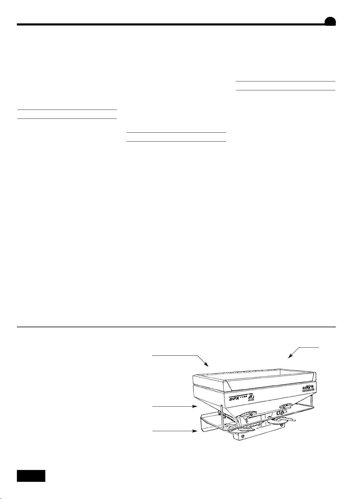
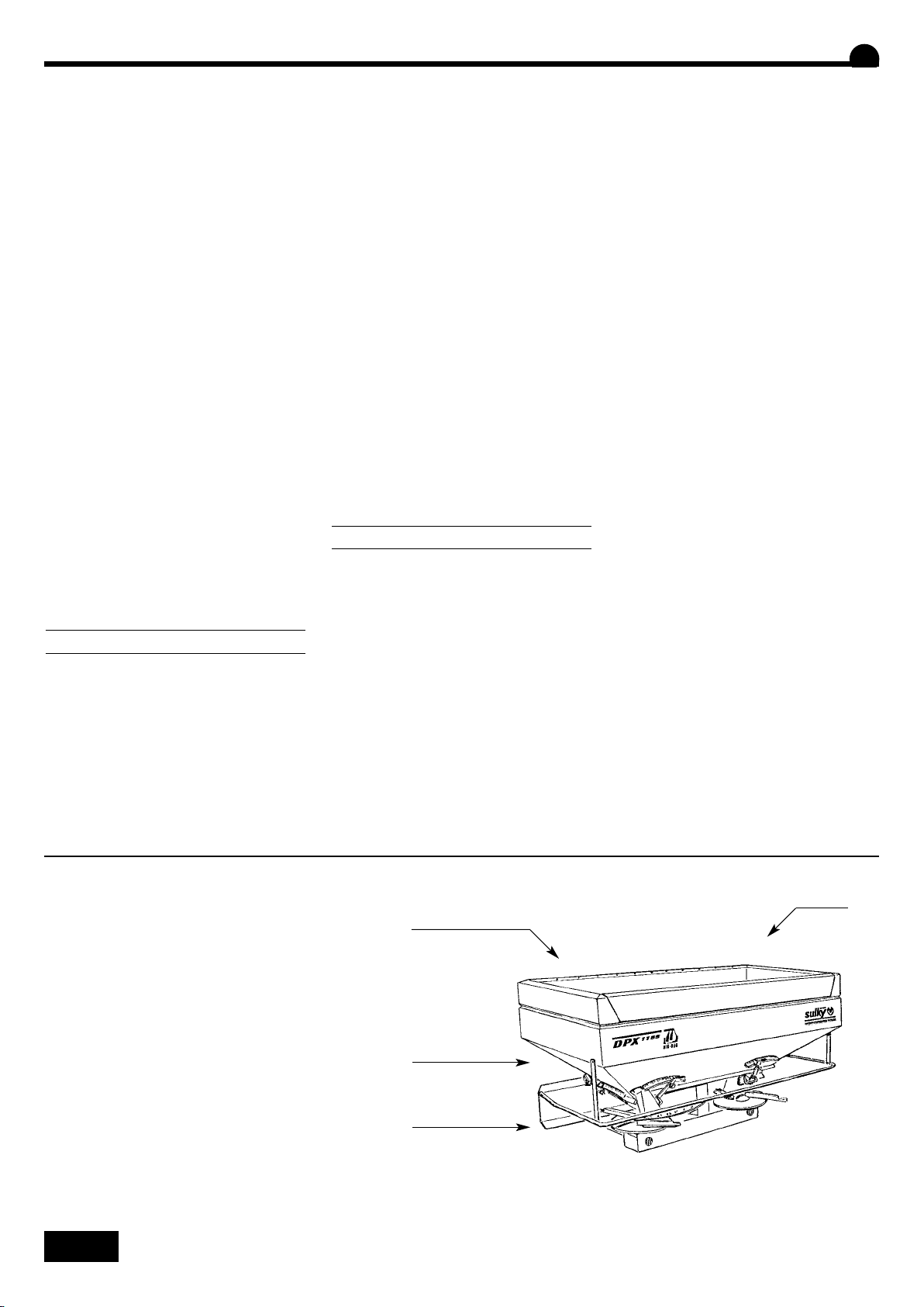
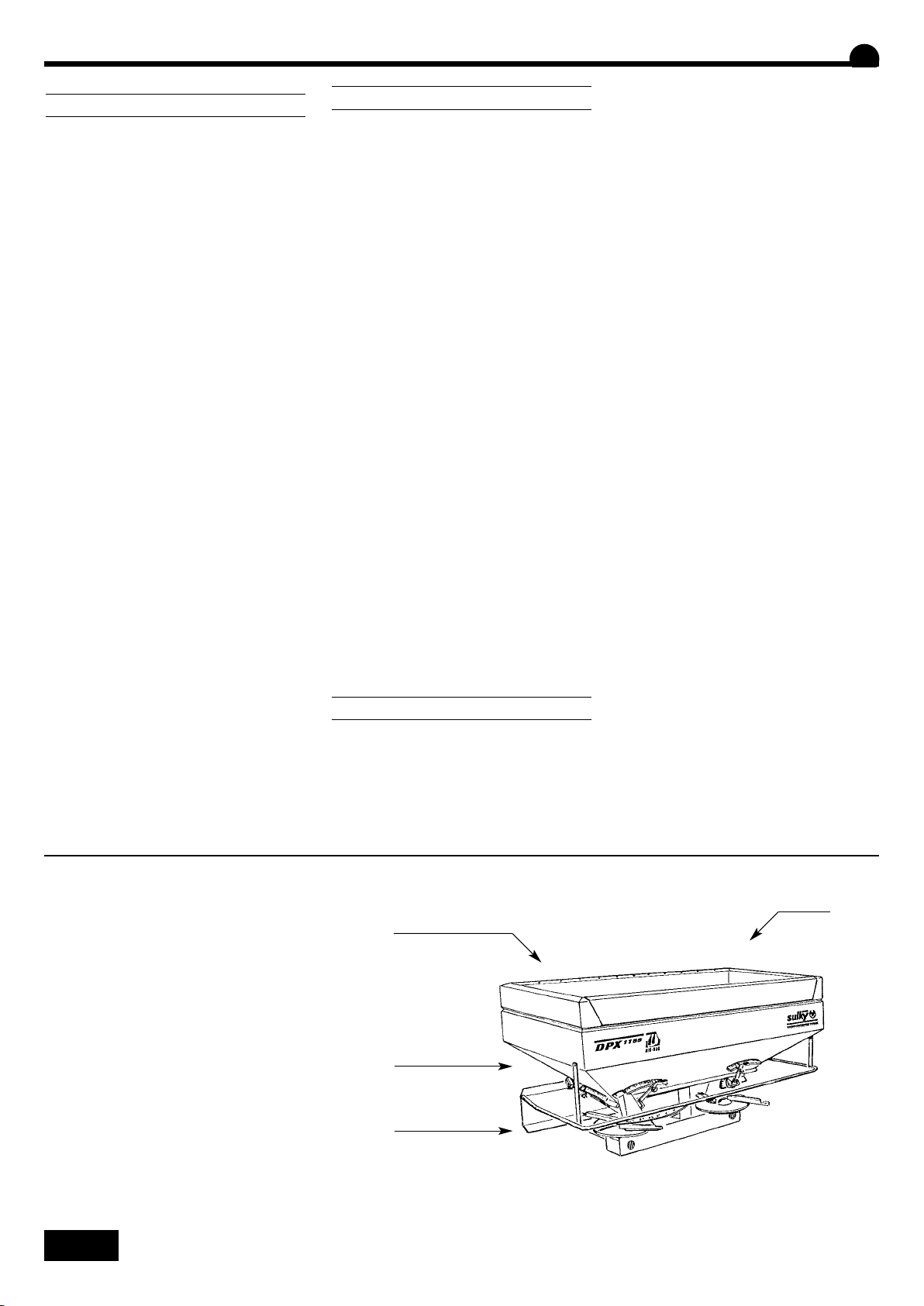
DPX 605 - 1155
DPX 1205 - 2005
Lever la machine avec
précaution, vérifier qu'il n'y
ait personne autour.
Retirer toutes fixations ou
protections mises sur le DPX,
nécessaires au transport.
Charge maximum :
DPX 1155 = 1200 kg
DPX 2005 = 2200 kg
Take care when lifting the
machine; check that there is
no-one around.
Remove all guards and
fixtures installed on the DPX
for transport purposes.
Maximum capacity:
DPX 1155 = 1200 kg
DPX 2005 = 2200 kg
B
Maschine vorsichtig heben
und sich vergewissern, daß
sich niemand im
Maschinenbereich aufhält.
Alle für den Transport des
DPX notwendigen
Befestigungen oder
Schutzvorrichtungen entfernen.
Höchstlast:
DPX 1155 = 1200 kg
DPX 2005 = 2200 kg
12
Page 15

Mise en route
Start-up
Inbetriebsetzung
A
Utilisation
• Au moment de la livraison, vérifier que l’appareil vous est
livré complet.
Assurez-vous qu'il n'y ait pas de corps étrangers dans la
trémie.
• Le DPX ne doit être utilisé que pour les travaux pour
lesquels il a été conçu.
Vérifier que la machine n’a subi aucun dommage en cours
de transport et qu’il ne manque aucune pièce.
Seules les réclamations formulées à réception de la machine
pourront être prises en considération.
Faire constater d’éventuels dégâts par le transporteur.
En cas de doute ou de litige, adressez-vous à votre revendeur.
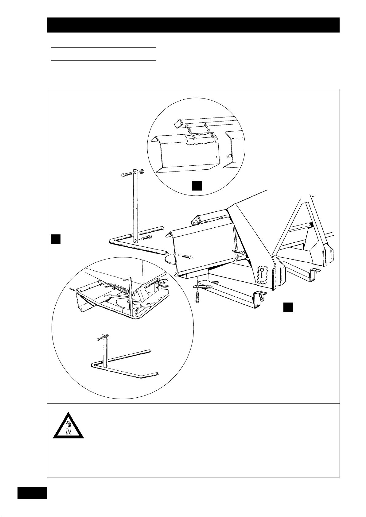
Montage des béquilles
B
• A la réception de votre DPX, veuillez monter les béquilles de
parking qui vous aideront à atteler plus facilement la
machine au tracteur.
Montage du déflecteur avant (605 - 805 - 1155)
C
• Monter les déflecteurs sur le châssis du DPX.
Montage de l’arceau de sécurité
D
• Monter l’arceau à la trémie et au déflecteur avant. Il doit
être absolument monté avant l’utilisation du DPX.
Manutention
E
• Utiliser l’anneau prévu à cet effet dans la trémie.
• Utiliser cet anneau que trémie vide.
F
1
Use
A
• Check that your equipment is complete on delivery.
Make sure that there are no foreign bodies in the hopper.
• The DPX should only be used for tasks for which it has been
designed.
Check that the machine has not suffered any damage
during transport and that no parts are missing.
Only claims made on taking delivery of the machine will be
considered.
Any damage should be reported to the carrier.
If in doubt or in the event of any complaint, please contact
your dealer.
A
Benutzung
• Bei Lieferung prüfen, ob das Gerät komplett ist.
Prüfen, ob sich kein Fremdkörper im Behälter befindet.
• Der DPX darf nur für die Arbeiten benutzt werden, für die
er bestimmt ist.
Prüfen, ob die Maschine nicht während des Transports beschädigt worden ist und kein Teil fehlt.
Nur bei Abnahme formulierte Reklamationen können
berücksichtigt werden.
Eventuelle Schäden vom Spediteur feststellen lassen.
Im Zweifel- oder Streitfall Ihren Verkäufer informieren.
Fitting the supports
B
• When you receive your DPX, please fit the parking supports
which will help you to hitch the machine to your tractor
more easily.
Fitting the front deflector (605, 805 and 1155)
C
• Fit the deflectors to the DPX frame.
Fitting the protective bar
D
• Fit the bar to the hopper and the front deflector. It is vital
that the protective bar is mounted before using the DPX.
E
Handling
• Use the specially provided ring in the hopper.
• Only use this ring with the hopper empty.
Montage der Stützen
B
• Bei Empfang Ihres DPX die Abstellstützen montieren, die
den Anbau der Maschine am Schlepper erleichtern.
Montage des vorderen Begrenzers (605 - 805 - 1155)
C
• Die Begrenzer auf dem Rahmen des DPX montieren
Montage der Sicherheitsbögen
D
• Den Bogen am Behälter und am vorderen Begrenzer
montieren. Er muß unbedingt vor Benutzung des DPX
montiert sein.
GB
D
E
Handhabung / Anheben
• Die dafür in der Behältermitte vorgesehene Aufhängöse
verwenden.
13
Page 16
Mise en route
Start-up
Inbetriebsetzung
F G
A
B
C
1
35°
35°
A
A
Travailler avec une
transmission protégée en
bon état, conforme aux
normes en vigueur.
Respecter le régime de prise
de force de 540 tr/min.
Aucune garantie ne sera
accordée pour des dégâts
causés sur le bloc 3 renvois,
par une transmission dont la
longueur n’aura pas été
ajustée au tracteur.
B
C
B
C
Ensure that your PTO drive
assembly is guarded, in good
condition and complies with
current standards.
Comply with the PTO speed
of 540 rpm.
The guarantee will not cover
damage caused to the
central gearbox assembly by
the PTO shaft if its length
has not been adjusted to the
tractor.
Mit einem geschützten
Antrieb in gutem Zustand
arbeiten, der den gültigen
Normen entspricht.
Die Zapfwellendrehzahl von
540 U/Min einhalten.
Keine Garantie für Schäden,
die auf dem 3Vorgelegeblock durch einen
Antrieb verursacht werden,
dessen Länge nicht dem
Schlepper angepaßt worden
ist.
2
14
Page 17

Mise en route
Start-up
Inbetriebsetzung
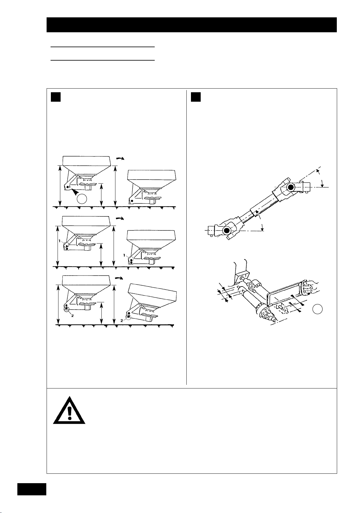
F
Attelage
F
• Le DPX est équipé d’un attelage 3 points catégorie II avec
chape inférieure.
• La position du DPX au travail est horizontale (A=B) et (C)
à 70 cm, utiliser la flèche de niveau pour régler l’aplomb.
Transmission
G
• Lire attentivement la notice jointe avec la prise de force.
• Angle de la transmission :
Pour garder votre cardan en bon état de fonctionnement,
respecter les positions de travail dans la limite de l’angle
maximum de 35°.
Hitching gear
F
• The DPX is fitted with a class II three-point hitch with a
bottom fork.
• The working position of the DPX is horizontal (A=B) and
(C) 70 cm above the ground; use the level indicator
adjust the spreader perpendicular.
G
Drive assembly
• Read the instructions provided with the PTO carefully.
to
• Montage :
Graisser l’arbre d’entrée du renvoi de l’appareil avant
d’emboîter la transmission.
• Longueur du cardan :
- Vérifier que la longueur du cardan est bien adaptée à
votre tracteur.
- Laisser un jeu de 3 cm à chaque extrémité .
• La prise de force est équipée d’un limiteur de couple qui
stoppe la transmission lorsque le couple dépasse la valeur
de tarage. Il se réengage automatiquement en réduisant la
vitesse ou en arrêtant la PTO.
GB
• Assembly :
Grease the equipment's transmission input shaft before
fitting the drive assembly.
• Universal shaft length :
- Check that the length is adapted to your tractor.
- Leave a clearance of 3 cm at each end .
• The PTO is equipped with an automatic torque limiter which
stops the PTO shaft whenever the torque exceeds the
calibration setting. It is automatically re-engaged by
reducing speed or stopping the PTO.
• Drive angle:
To keep your universal shaft in good working order, make
sure that the working positions do not exceed the maximum
angle of 35°.
F
Anbau
• Der DPX ist mit einer Dreipunktkupplung Klasse II mit
unterer Befestigungsklammer ausgerüstet.
• Die Arbeitsstellung des DPX ist waagerecht (A=B) und (C)
70 cm vom Boden entfernt. Den Kontrollpfeil
um die Senkrechtstellung zu regeln.
Antrieb
G
• Die der Zapfwelle beiliegende Anweisung sorgfältig lesen.
• Antrieb:
Damit die Gelenkwelle in gutem Funktionszustand bleibt,
die Arbeitsstellungen innerhalb des maximalen Winkels von
35° einhalten.
benutzen,
D
• Montage :
Die Antriebswelle des Gerätevorgeleges vor Einhängen des
Getriebes schmieren.
• Länge der Gelenkwelle :
- Prüfen, ob die Gelenkwelle Ihrem Schlepper angepaßt ist.
- An jedem Ende ein Spiel von 3 cm lassen .
• Die Zapfwelle ist mit einem Drehmomentbegrenzer
ausgerüstet, die den Antrieb stoppt, sobald das
Drehmoment den Tarierwert überschreitet. Er schaltet sich
automatisch wieder ein, wenn die Geschwindigkeit
reduziert oder die Zapfwelle ausgeschaltet wird.
15
Page 18
Mise en route
Start-up
Inbetriebsetzung
H
1
3
2
16
Montage des commandes :
voir notice jointe.
Attention huile sous
pression.
Stocker les commandes ou
les flexibles hydrauliques
aux endroits prévus à cet
effet sur la machine.
Fitting the controls: see
enclosed instructions
Caution: oil under pressure.
Store the controls or the
hydraulic hoses in the
specially-provided areas on
the machine.
Montage der Betätigungen:
vgl. beiliegende Anweisung
Vorsicht, Öl steht unter
Druck.
Betätigungsvorrichtungen
oder Hydraulikschläuche an
den dafür auf der Maschine
vorgesehenen Stellen
aufbewahren.
Page 19

Mise en route
Start-up
Inbetriebsetzung
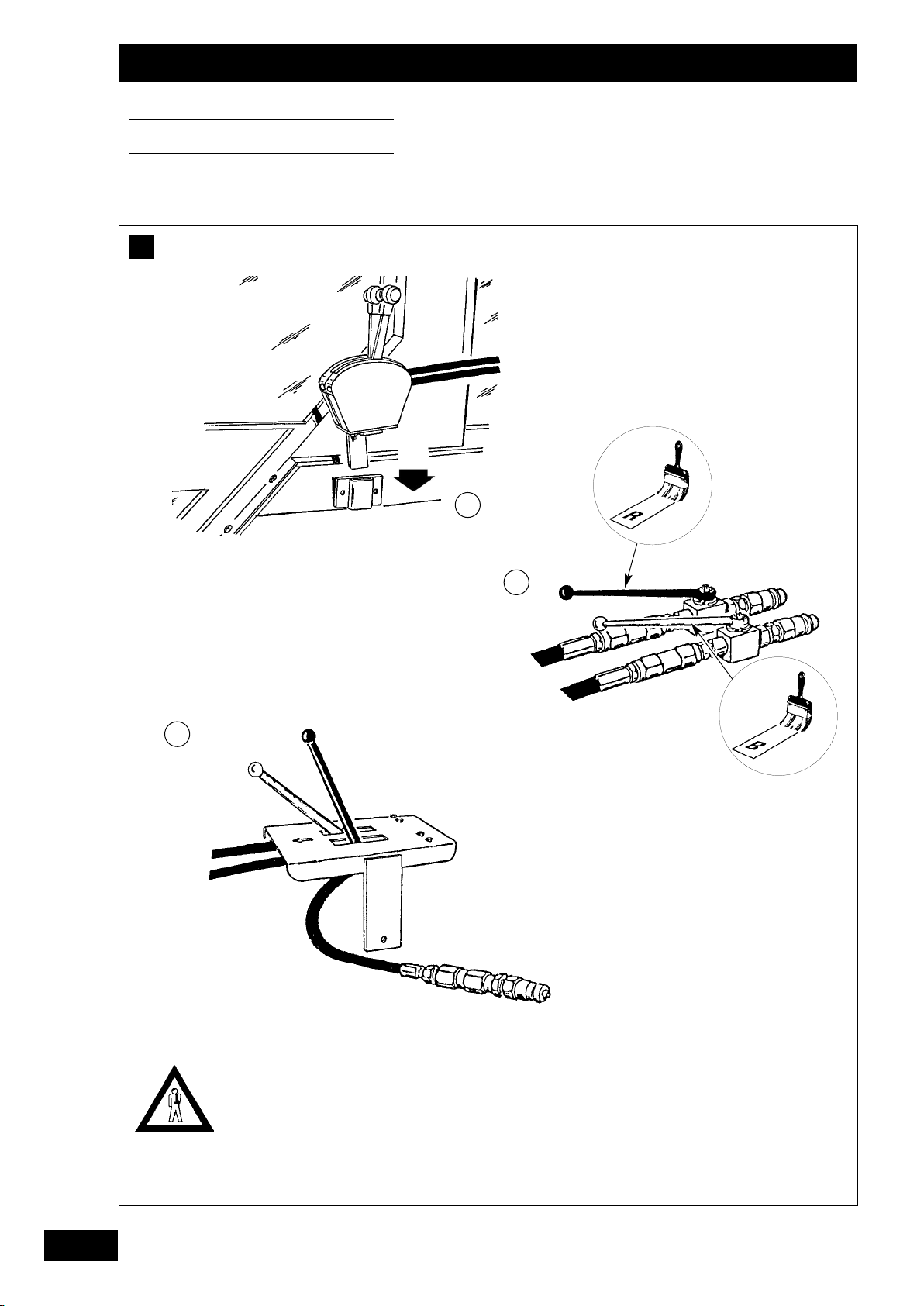
Branchement des commandes
H
a) Commande téléflexible
• Monter le support de commande sur le tracteur
• Pour cela, baisser l’appareil, présenter le boîtier de
commande et son support sur le côté droit de la cabine et
après avoir déterminé un emplacement, percer et fixer ce
dernier.
b) Commande hydraulique
• Montage avec 2 distributeurs simple effet .`
- L’ouverture des trappes se fait indépendamment par les
deux simple effet. Pour ouvrir ou fermer les trappes, on
agit sur le levier du distributeur du tracteur. Un robinet
permet d’isoler le circuit pour éviter l’ouverture
intempestive des trappes au transport (non étanchéité
des distributeurs par exemple).
- Robinet rouge pour la trappe gauche,
- Robinet bleu pour la trappe droite.
.
• Montage avec 1 distributeur simple effet.
- L’ouverture des trappes se fait par un simple effet. Les 2
robinets montés à l’extérieur de la cabine permettent de
commander indépendamment une trappe par rapport à
l’autre. Cela permet aussi d’isoler le circuit pour éviter
l’ouverture intempestive des trappes au transport. Les
deux montages disposent d’un limiteur de débit fixe évitant
les manœuvres brutales.
- Utilisation
Si vous voulez épandre côté droit :
- fermer les trappes,
- tirer sur le levier rouge,
- actionner le distributeur hydraulique du tracteur.
Si vous voulez épandre côté gauche :
- Utiliser le levier bleu.
Pour épandre avec les deux côtés :
- actionner le distributeur (pression),
- pousser le levier rouge ou bleu et réouvrir les trappes.
.
F
GB
Control connections
H
a) Remote control cables
• Mount the control support on the tractor
• In order to do this, lower the equipment, locate a suitable
position on the right-hand side of the cab, drill and fit the
control unit.
b) Hydraulic control
• Assembly with two single-action control valves
- The flaps are opened independently by the two single-
action control valves. The tractor control lever is used to
open and close the flaps. A cock is fitted to cut off the
circuit to prevent the flaps from opening whilst in transit
(control valve leakage).
- The red one for the LH flap
- The blue one for the RH flap
H
Anschluß der Betätigungsgehäuse
a) Fernbetätigung durch Bodenzug
• Schaltgehäuse auf Schlepper montieren.
• Dafür das Gerät senken, Betätigungsgehäuse und seinen
Träger an die rechte Kabinenseite halten und nach
Ermittlung der gewünschten Ansatzstelle bohren und
befestigen.
b) Hydraulikfernbetätigung
• Montage mit 2 einfachwirkenden Steuerventilen
- Die Öffnung der Schieber erfolgt unabhängig durch die
beiden einfachwirkenden Steuerventile. Zum Öffnen und
Schließen der Schieber das Steuerventil des Schleppers
betätigen. Ein Hahn erlaubt das Isolieren der Leitung, um
das unerwünschte Öffnen der Schieber beim Transport zu
verhindern (undichte Schieber).
- Roter Hahn für linke Klappe
- Blauer Hahn für rechte Klappe
.
.
• Assembly with one single-action control valve .
- The flaps are opened by a single action. The flaps can be
controlled independently of each other by using the two
cocks fitted on the outside of the cab. These cocks also
cut off the circuit to prevent the flaps from opening whilst
in transit. Both assemblies have a fixed flow limiter to
avoid sudden operation.
- Use
For right-hand side spreading:
- close the shutters,
- pull the red lever,
- activate the tractor hydraulic distributor.
For left-hand side spreading:
- use the blue lever.
For full spreading:
- activate the distributor (pressure),
- push the red lever and open the shutters.
• Montage mit 1 einfachwirkenden Steuerventil
- Die Schieber werden durch 1 einfachwirkendes
Steuerventil geöffnet. Die beiden auf der Außenseite der
Kabine montierten Hähne erlauben die Betätigung eines
Schiebers unabhängig vom anderen sowie das Isolieren
der Leitung zum Verhindern eines unerwünschten Öffnens
der Schieber beim Transport. Beide Montagemöglichkeiten
umfassen einen festen Durchflußregler zur Vermeidung
heftiger Betätigungen.
- Benutzung
Streuung rechts:
- Schieber schließen,
- am roten Hebel ziehen,
- Hydrauliksteuerventil des Schleppers betätigen.
Streuung links:
- blauen Hebel benutzen.
Beidseitige Streuung:
- Steuerventil betätigen (Druck),
- roten Hebel drücken und Schieber öffnen.
.
D
17
Page 20
Mise en route
Start-up
Inbetriebsetzung
I
b)
1
2
900
800
700
600
500
400
300
d)
Mini
c)
200
100
50
18
Ne pas stationner dans la
trémie au travail !
Do not stand in the hopper
while in operation!
Aufenthalt im Behälter
während der Arbeit verboten.
Page 21

Mise en route
Start-up
Inbetriebsetzung
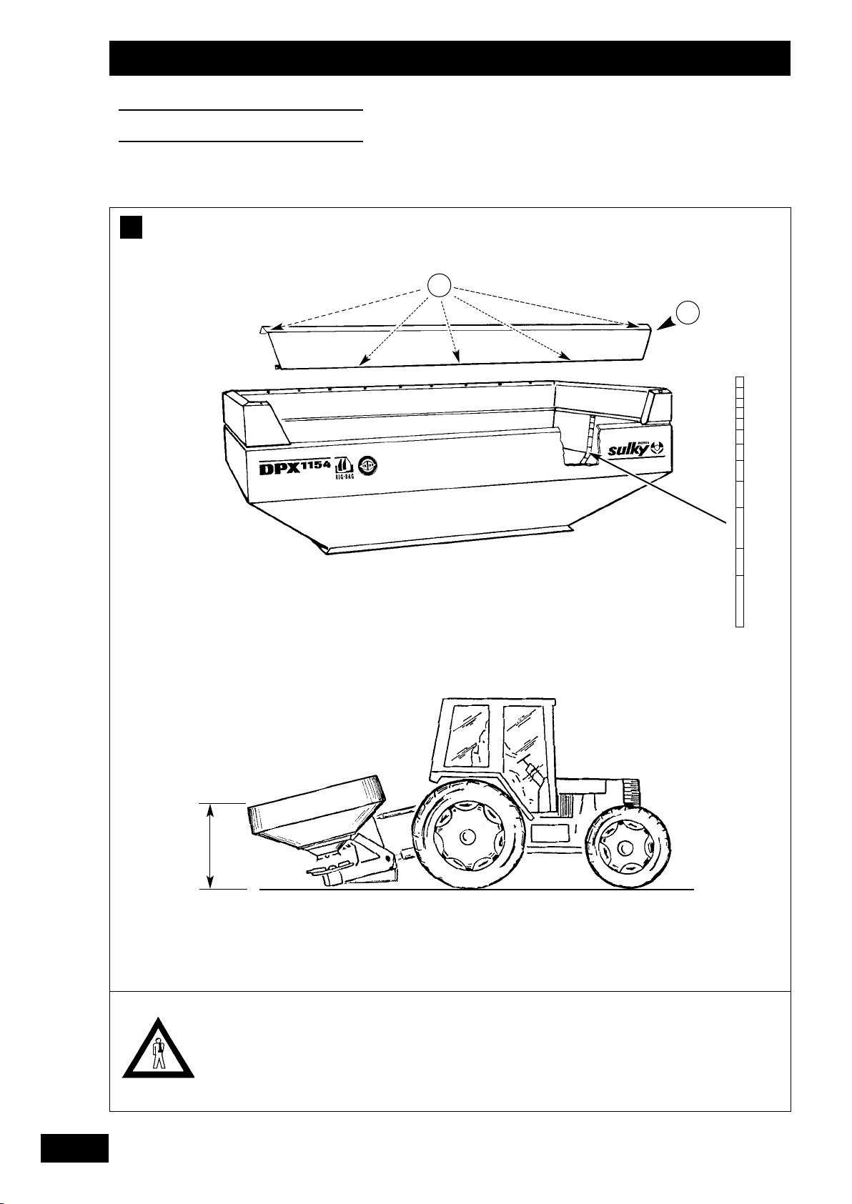
Chargement
I
a) Tamis
- Vérifier qu'il n'y ait pas de corps étranger dans la trémie
avant le chargement.
- Bloquer les tamis en position basse.
Ne jamais travailler sans les tamis.
b) Le panneau arrière est démontable de manière à baisser
la hauteur de chargement. (1155 - 2005)
d) Chargement
• Pour baisser la hauteur de chargement, régler l’attelage du
tracteur de manière à ce que le DPX soit incliné et repose
sur ses béquilles.
J
Vidange
• Démonter les disques d'épandage
F
- Retirer les vis de fixation.
- Soulever le panneau de manière à sortir ses extrémités
des demi réhausses droite et gauche.
c) L'indicateur de capacité donne la valeur en litre de
produit pour les deux côtés.
Loading
I
a) Sifting screen
- Check that there are no foreign bodies in the hopper before
loading.
- Secure the sifting screen in the bottom position.
Never use the spreader without the sifting screens.
b) The rear panel may be removed to reduce the loading
height. (1155 - 2005)
- Remove the securing screws.
- Lift the panel so that both ends come out of the RH and
LH extensions.
c) The capacity indicator gives the value in litres of product
for the two sides.
• Récupérer l'engrais dans un bac côté droit puis gauche en
agissant manuellement sur le levier de réglage ou sur les
téléflexibles correspondants.
• La machine doit être à l'arrêt.
• Respecter le sens de montage des disques.
• Bien resserrer les disques.
d) Loading
• To lower the loading height, adjust the tractor hitch to tip
the DPX on to its parking supports..
J
Emptying
• Remove the spreading discs.
• Recover the fertilizer in a bucket on the RH side, followed
by the LH side, by manually activating the setting lever or
the corresponding remote control cables.
• The machine must be stopped.
• Make sure the discs are refitted the right way round.
• Tighten the discs fully.
GB
D
Laden
I
a) Siebe
- Vor dem Laden prüfen, ob sich kein Fremdkörper im
Behälter befindet.
- Siebe in unterer Stellung blockieren
Niemals ohne die Siebe arbeiten.
b) Die hintere Platte kann zum Reduzieren der Ladehöhe
abgenommen werden. (1155 - 2005)
- Befestigungsschrauben abnehmen.
- Platte anheben, bis ihre Enden aus den rechten und
linken Halbaufsätzen treten.
c) Inhaltsanzeiger gibt den Wert in Litern/Produkt für beide
Seiten an.
d) Laden
• Zum Reduzieren der Ladehöhe die Schlepperkupplung so
einstellen, daß der DPX geneigt ist und auf seinen Stützen
aufliegt.
J
Entleeren
• Streuscheiben demontieren.
• Dünger rechts und dann links in einer Wanne durch
Handbetätigung des Einstellhebels oder Betätigung der
oder auf die entsprechenden Bodenzüge auffangen.
• Die Maschine muß abgeschaltet sein.
• Montagerichtung der Scheiben respektieren.
• Scheiben wieder gut festziehen.
19
Page 22
Réglages
Settings
Einstellungen
A
2
1
La réalisation de l’essai de
débit est vivement
conseillée pour avoir une
bonne précision de
réglage. Les tableaux de
réglage ne sont donnés
qu’à titre indicatif.
Utiliser la réglette pour
déterminer votre réglage.
Cette méthode pratique
tient compte des
différentes conditions
influant le débit.
A test run is strongly
recommended to obtain an
accurate setting. The
setting charts are provided
as an indication only.
Use the slide calculator to
determine your setting.
This practical method takes
account of the various
conditions affecting the
flow.
Wir empfehlen eine
Abdrehprobe zwecks
genauer Einstellung.
Die Streumengentabellen
dienen nur als Hinweis.
Einstellskala zum
Bestimmen Ihrer
Einstellung benutzen. Diese
praktische Methode
berücksichtigt die
verschiedenen
Bedingungen, die die
Streumenge beeinflussen.
20
Page 23

Réglages
Settings
Einstellungen
F
Réglage débit
A
Le réglage de débit s’effectue en modifiant l’ouverture de la
trappe par l’intermédiaire d’une butée sur un repère gradué.
a) Utilisation :
- Desserrer la poignée de la butée
- Positionner le repère choisi face à l’index.
- La lecture se fait sur la partie large de la butée
- Bien resserrer la poignée.
Setting the flow
A
The flow is set by adjusting the flap opening with the stop on
the graduated marker.
a) Use:
- Unscrew the stop handle
- Position the mark selected opposite the index.
- The wide part of the stop
setting.
- Tighten the handle.
should be used to read the
.
b) Choix du repère :
Le choix du repère selon votre débit/ha se fait de deux
façons :
• Utilisation des tableaux de débit fournis avec le manuel :
choisir l’engrais correspondant au mieux à votre produit, lire
directement le réglage théorique et faire un essai de
contrôle.
• Utilisation de la réglette de débit fournie avec la
machine.
2
GB
b) Choosing the mark:
The mark depends on your quantity per hectare and is
selected in two ways:
• Using the flow charts supplied with the manual: choose the
fertilizer which corresponds most closely to your product,
read off the theoretical setting and carry out a test run.
• Using the slide calculator supplied with the machine.
Streumengeneinstellung
A
Die Streumengeneinstellung erfolgt durch Ändern der
Schieberöffnung mittels eines Anschlags auf einer Skala.
a) Benutzung:
- Griff des Anschlags lockern
- Gewählte Markierung dem Index gegenüberstellen.
- Der Wert wird auf dem breiten Teil des Anschlags
abgelesen
- Griff wieder gut anziehen.
.
.
D
b) Wahl der Markierung:
Die Wahl der Markierung gemäß Streumenge/ha ist auf
zwei Arten möglich:
• Benutzung der mit dem Handbuch gelieferten
Streumengentabellen: den am besten Ihrem Produkt
entsprechenden Dünger wählen, theoretische Einstellung
direkt ablesen und eine Kontrollprobe durchführen.
• Benutzung der mit der Maschine gelieferten Einstellskala.
21
Page 24
Réglages
Settings
Einstellungen
B
DPX 1205 - 1505 - 1805 - 2005
4
3
1
2
DPX 605 - 805 - 1155
22
Attention à la précision de
votre balance.
Ne pas oublier de retirer le
poids du bac dans la dose
récupérée de l’essai.
2
Make sure your scales are
accurate.
Do not forget to subtract
the weight of the bucket
from the amount collected
during the test.
3
1
3
Waage muß genau wiegen.
Nicht vergessen,
Wannengewicht von
erhaltener Düngermenge
abzuziehen.
Page 25

Réglages
Settings
Einstellungen
F
B
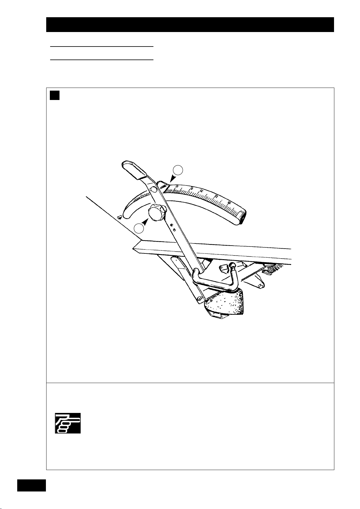
Essais de débit
L’essai est à réaliser avant chaque épandage afin de mettre la
bonne dose par hectare. La nature des engrais est tellement
variée qu’il est obligatoirement nécessaire de l’effectuer.
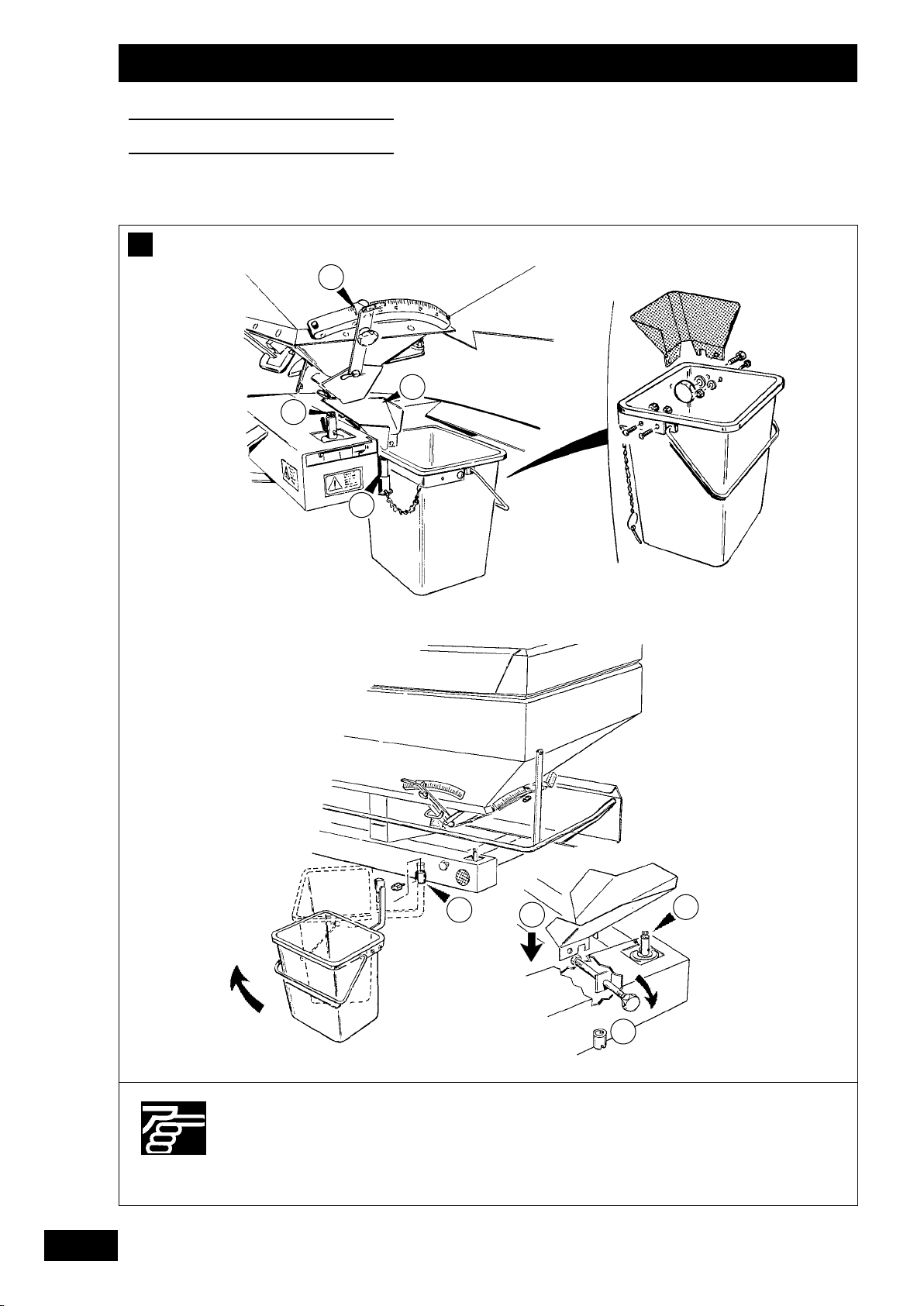
a) Mise en place de l’essai :
La machine doit être à l'arrêt.
L’essai de débit s’effectue coté droit.
Retirer le disque en dévissant la vis M10 inox et la remettre
sur son axe.
Mettre le bac en place en mettant l'axe du seau à la
charnière arrière du châssis, et le faire pivoter. (à réaliser
après l’étape
Bigbag)
pour les 1205 - 1505 - 1805 - 2005
Mettre l’entonnoir sur le seau et le fixer à l’aide de la
molette.
Mettre la goulotte au repère 110.
Flow rate tests
B
The test is to be carried out before each spreading operation so
that the correct quantity per hectare is applied. The variable
nature of fertilizer is such that this process is absolutely necessary.
a) Setting up the test:
The machine must be off.
The test is carried out on the RH side.
Remove the disc by extracting the stainless steel M10
screw and refitting it into the shaft.
Put the bin into place by inserting the bucket pin into the
rear frame hinge and swinging it round (to be carried out
after step
on 1205, 1505, 1805 and 2005 Bigbag).
Put the funnel on to the bucket and secure with the knob.
Set the chute to the 110 mark.
b) Réglages avec tableaux
- Mettre le repère au réglage correspondant à votre engrais
lu dans les tableaux joints.
- Contrôler ce repère par un essai de débit. en parcourant la
distance correspondant à votre largeur de travail :
12 m . . . . . . . . . . . . . . . . . . . . . . .41,7 m
15 m . . . . . . . . . . . . . . . . . . . . . . .33,4 m
18 m . . . . . . . . . . . . . . . . . . . . . . .27,8 m
21 m . . . . . . . . . . . . . . . . . . . . . . .23,8 m
24 m . . . . . . . . . . . . . . . . . . . . . . .20,8 m
28 m . . . . . . . . . . . . . . . . . . . . . . .17,9 m
- Peser la quantité obtenue et multiplier par 40.
GB
b) Setting with the charts
- Position the marker at the setting corresponding to your
fertilizer as indicated in the enclosed tables.
- Check this setting by a test run over a distance
corresponding to your working width :
12 m . . . . . . . . . . . . . . . . . . . . . . .41.7 m
15 m . . . . . . . . . . . . . . . . . . . . . . .33.4 m
18 m . . . . . . . . . . . . . . . . . . . . . . .27.8 m
21 m . . . . . . . . . . . . . . . . . . . . . . .23.8 m
24 m . . . . . . . . . . . . . . . . . . . . . . .20.8 m
28 m . . . . . . . . . . . . . . . . . . . . . . .17.9 m
- Weigh the quantity obtained and multiply by 40.
B
Abdrehprobe
Die Probe ist vor jedem Streuen durchzuführen, damit die
richtige Menge pro Hektar gestreut wird. Die Eigenschaften
der Dünger sind so unterschiedlich, daß eine Abdrehprobe
unerläßlich ist.
a) Vorbereitung der Abdrehprobe:
Die Maschine muß abgeschaltet sein.
Die Abdrehprobe erfolgt auf der rechten Seite.
Scheibe durch Lösen der rostfreien Schraube M10
herausnehmen, Schraube wieder auf dem Bolzen
anbringen.
Durch Anbringen des Eimerbolzens am hinteren Scharnier
des Rahmens die Mulde positionieren und drehen. (nach
durchzuführen für die 1205 - 1505 - 1805 - 2005
Etappe
Bigbag)
Trichter auf dem Eimer anbringen und mit Hilfe des
Rädchens befestigen.
Das Zuführorgan auf die Markierung 110 stellen.
D
b) Einstellungen mit Tabellen
- Markierung auf die in den beiliegenden Tabellen
abgelesene und Ihrem Dünger entsprechende Einstellung
stellen.
- Diese Markierung durch eine Abdrehprobe unter
Zurücklegung einer Ihrer Arbeitsbreite entsprechenden
Strecke kontrollieren :
12 m . . . . . . . . . . . . . . . . . . . . . . .41,7 m
15 m . . . . . . . . . . . . . . . . . . . . . . .33,4 m
18 m . . . . . . . . . . . . . . . . . . . . . . .27,8 m
21 m . . . . . . . . . . . . . . . . . . . . . . .23,8 m
24 m . . . . . . . . . . . . . . . . . . . . . . .20,8 m
28 m . . . . . . . . . . . . . . . . . . . . . . .17,9 m
- Erhaltene Menge wiegen und mit 40 multiplizieren.
23
Page 26
Réglages
Settings
Einstellungen
2
1
3
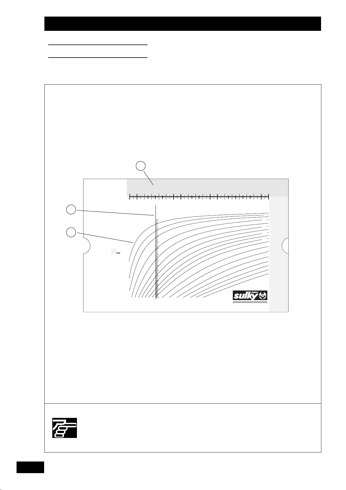
Mode d'emploi
Placez la barre
rouge sur le
poids d'engrais
obtenu (zone
jaune). Ensuite,
choississez dans
la zone bleue la
courbe qui
correspond au
débit recherché.
Suivez cette
courbe. Dès que
vous coupez la
barre rouge, vous
pouvez lire un
repère compris
entre 1 et 5.
Avec
ce repère,
revenez en au
recto de cette
réglette.
Pour encore plus
de précision,
faite une pesée
de contrôle avec
le repère trouvé
(essai sur même
distance). Poids
d'engrais obtenu
x 40 = débit en
Kg/Ha
F / GL /H.00
6
Poids obtenu lors de l'essai (en Kg)
1 2 3 4 5 6 7 8 9 10111213141516171819 20
Réglette DPX
75
10
20
30
40
50
60
70
80
150
250
350
450
50
100
200
300
400
500
600
700
800
900
1000
1100
Débit recherché (en Kg/Ha)
1200
24
Bien suivre les instructions.
Follow the instructions
carefully.
Anweisungen einhalten.
Page 27

Réglages
Settings
Einstellungen
F
c) Réglage avec la réglette
Elle vous permet quel que soit l’engrais, de déterminer le
réglage de l’ouverture des trappes pour le débit désiré, avec
un seul essai sans utiliser les tableaux.
- Principe : (voir sur réglette)
- Mettre deux jalons espacés de la distance correspondant à
votre largeur d’épandage, exemple 20.80 m pour 24 m
d'épandage.
- Monter le kit d’essai de débit (voir page 23).
- Régler la butée de débit de la trappe droite au repère 35
(quel que soit votre débit).
- Laisser la trappe gauche fermée.
- Mettre la prise de force à 540 tr/min et parcourir la distance
d’essai à votre vitesse de travail.
- Peser la quantité obtenue (en retirant le poids du bac).
c) Setting with the calculator
Whatever the type of fertilizer used, the calculator will enable
you to determine the setting for the flap openings for the
required flow rate, with a single test without using the charts.
- Principle (see calculator)
- Place two markers at a distance corresponding to your
working width; e.g. 20.80 m for 24 m of spreading.
- Fit the calibration test kit (see page 23).
- Set the flow rate indicator for the RH flap to 35 (whatever
your flow rate).
- Leave the LH flap closed.
- Set the PTO to 540 rpm and cover the test distance at your
working speed.
- Weigh the quantity obtained (subtracting the weight of the
bucket).
- Au dos de la réglette placer la barre rouge
sur la partie haute
au poids que vous avez obtenu.
- Choisir la courbe
- Lire le repère de réglage à l’endroit où cette courbe coupe la
ligne rouge .
- Reporter sur les deux trappes du DPX le repère de réglage obtenu.
- Pour encore plus de précision, il est possible de faire un deuxième
test avec le repère déterminé au premier essai.
La quantité obtenue sera à multiplier par 40 (prendre la même
distance d'essai).
- On the back of the calculator, set the red bar
top section to the weight obtained.
- Choose the curve
- Read the setting mark at the point where the curve intersects
the red line .
- Apply the setting mark obtained to the two DPX flaps.
- For increased accuracy, it is possible to carry out a second
test at the mark determined during the first.
The quantity obtained is to multiplied by 40 (taking the same
test distance).
correspondant à votre dose hectare.
along the
relating to your quantity per hectare.
GB
c) Einstellung mit Einstellskala
Sie erlaubt die Einstellung der Schieberöffnung für die
gewünschte Streumenge unabhängig von der Düngerart und
mit einer einzigen Abdreh ohne Benutzung der Tabellen
festzulegen.
- Prinzip (vgl. Meßskale).
- Zwei Feldmarkierungen anbringen, deren Abstand Ihrer
Streubreite entspricht (B.: 20,80 m für 24 m Streubreite).
- Abdrehprobe-Kit anbringen (vgl. S. 23).
- Streumengenanschlag des rechten Schiebers auf die
Markierung 35 stellen (unabhängig von Ihrer Streumenge).
- Linken Schieber geschlossen lassen.
- Zapfwelle auf 540 U/Min bringen und die Probestrecke mit
Ihrer Arbeitsgeschwindigkeit zurücklegen.
- Erhaltene Düngermenge wiegen (Wannengewicht abziehen).
- Den roten Streifen
oberen Teil auf das erzielte Gewicht stellen. Die Ihrer
Streumenge/ha entsprechende Kurve wählen.
- Den Einstellwert an der Stelle ablesen, an der diese Kurve die
rote Linie kreuzt.
- Die erhaltene Einstellmarkierung auf die beiden Schieber
des DPX übertragen.
- Zwecks noch genauerer Einstellung kann ein zweiter Test mit
der bei der ersten Probe festgelegten Markierung
durchgeführt werden.
Die erhaltene Menge mit 40 multiplizieren (diesselbe
Probestrecke fahren).
auf der Rückseite der Meßskale im
D
25
Page 28
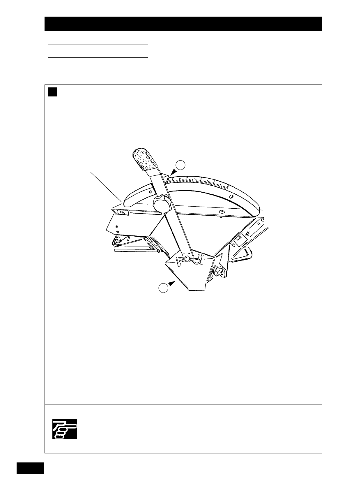
Réglages
Settings
Einstellungen
C
2
Pour un bon épandage, il
est indispensable de
maintenir les plateaux et
les pales d’éjection en bon
état.
1
For correct spreading, the
discs and the ejector
blades need to be kept in
good condition.
Streuscheiben und
Wurfschaufeln müssen für
ein gutes Streuergebnis in
gutem Zustand sein.
26
Page 29

Réglages
Settings
Einstellungen
F
Réglage largeur
C
La goulotte de réglage permet de changer le point de chute
de l’engrais sur le disque et donc de modifier la largeur de travail.
Ce réglage est continu et vous permet quel que soit l’engrais
granulé de trouver le réglage en ayant un recouvrement
optimum. La lecture se fait sur la partie la plus large du repère
a) Réglage avec tableaux
En consultant les tableaux, rechercher l’engrais qui se
rapproche le plus du produit que vous avez à épandre suivant
ses principales caractéristiques, à savoir : sa grosseur, sa
densité, sa forme et sa rugosité.
Mettre la goulotte au repère lu et serrer la molette.
Pour obtenir une grande largeur de travail, la structure et la
forme de l’engrais sont importantes, et il est préférable de
choisir le produit le mieux adapté. Les règles de la balistique
limitent les projections de granulés sur une grande largeur
dans les conditions suivantes :
Setting the width
C
The point where the fertilizer drops on to the disc, and
therefore the working width, can be adjusted by means of the
setting chute
fertilizer granules used, will enable you to find the setting
giving optimum coverage. The setting should be read at the
widest part of the marker .
a) Setting with the charts
By consulting the charts, search for the fertilizer which
corresponds most closely to the product to be spread by
referring to its main characteristics, i.e. size, density, shape and
roughness.
Set the chute to the mark indicated and tighten the knob.
To obtain a large working width, the structure and the shape
of the fertilizer are important and it is preferable to choose the
most suitable product. Laws of ballistics limit the projection of
granules over a wide area under the following conditions :
. This setting is continuous and, whatever the
.
- masse trop faible = grain très petit ou densité faible
- résistance dans l’air = très gros grain à faible densité, forme
irrégulière des grains (exemple : chlorure de potassium)
En général, les fabricants d’engrais précisent que, pour obtenir
une largeur effective de travail de 24 m, avec un granulé de
densité de 0,9 et plus, il est nécessaire que 50 % des grains
d’engrais soient d’un diamètre égal ou supérieur à 2,5 mm.
En pratique :
- un engrais coulant, fluide, s’échappe plus vite des pales
d’éjection, donc a moins de force de projection, et nécessite
parfois de régler les goulottes plus larges que les tableaux de
préconisation.
- à l’inverse, un engrais rugueux s’accroche plus longtemps
dans les pales d’éjection, acquiert alors plus de force de
projection pour aller loin et nécessite de régler les goulottes
moins larges que les tableaux de préconisation.
GB
- mass too low = very small grain or low density
- air resistance = very large grain with low density, irregular
grain shape (e.g. potassium chloride).
In general, fertilizer manufacturers specify that, to obtain an
effective working width of 24 m, using a granule with a density
of 0.9 or more, 50% of the fertilizer grains need to have a
diameter of at least 2.5 mm.
In practice :
- a loose, fluid fertilizer slides more quickly through the
ejector blades, has therefore less propulsive force, and
sometimes needs the chutes to be set wider than the chart
recommendations.
- on the other hand, a rough fertilizer sticks to the ejector
blades longer, thereby acquiring greater propulsive force to
travel further and needs the chutes to be set less wide than
the chart recommendations.
D
Breiteneinstellung
C
Das Einstellzuführorgan erlaubt, den Punkt, an dem der
Dünger auf die Scheibe prallt und damit die Arbeitsbreite zu
ändern. Dieser Vorgang erfolgt stufenlos und erlaubt Ihnen,
unabhängig von der Art des Granulats die Einstellung und
gleichzeitig eine optimale Überlappung zu erhalten. Die
Ablesung erfolgt auf dem breitesten Teil der Markierung .
a) Einstellung mit Tabellen
Auf den Tabellen den Dünger suchen, der dem von Ihnen zu
streuenden Produkt in seinen Haupteigenschaften am
ähnlichsten ist, bzw. Dicke, Dichte, Form und Rauheit.
Zuführorgan auf die abgelesene Markierung stellen und
Rädchen anziehen.
Der Aufbau und die Form des Düngers sind zur Erzielung einer
großen Arbeitsbreite wichtig, deshalb sollte das am besten
geeignete Produkt gewählt werden. Die Ballistikregeln
schränken das Auswerfen von Granulat unter folgenden
Bedingungen ein :
- zu geringe Masse = Korn sehr klein oder von geringer
Dichte
- Widerstand in der Luft = Korn sehr dick, unregelmäßige
Form der Körner (B.: Kaliumchlorid)
Im allgemeinen präzisieren Düngerhersteller, daß zur
Erzielung einer effektiven Arbeitsbreite von 24 m mit einem
Granulat von 0,9 Dichte und mehr 50 % der Düngerkörner
einen Durchmesser haben müssen, der gleich oder größer als
2,5 mm ist.
In der Praxis :
- ein glatter und dünnflüssiger Dünger fällt schneller von den
Wurfschaufeln, hat also weniger Spritzkraft. Deshalb
müssen die Zuführorgane manchmal breiter eingestellt
werden, als in den Tabellen empfohlen.
- dagegen bleibt ein rauher Dünger länger an den
Wurfschaufeln hängen, erwirbt also mehr Spritzkraft für
größere Reichweite. Deshalb müssen die Zuführorgane
schmaler eingestellt werden, als in den Tabellen empfohlen.
27
Page 30
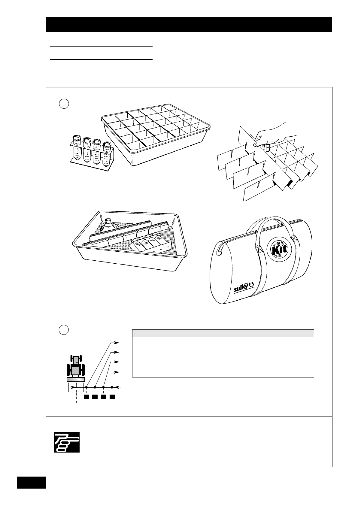
Réglages
Settings
Einstellungen
1
28
2
12m 15m 16m 18m 20m 21m 24m 28m 32m 36m
1,50m 1,80m 2,00m 2,25m 2,50m 2,60m 3,00m 3,50m 4,00m 4,50m
1
3,00m 3,70m 4,00m 4,50m 5,00m 5,20m 6,00m 7,00m 8,00m 9,00m
2
4,50m 5,60m 6,00m 6,75m 7,50m 7,80m 9,00m 10,50m 12,00m 13,50m
3
6,00m 7,50m 8,00m 9,00m 10,00m 10,50m 12,00m 14,00m 16,00m 18,00m
4
Pour un bon épandage, il
est indispensable de
maintenir les plateaux et
les pales d’éjection en bon
état.
For correct spreading, the
discs and the ejector
blades need to be kept in
good condition.
Streuscheiben und
Wurfschaufeln müssen für
ein gutes Streuergebnis in
gutem Zustand sein.
Page 31

Réglages
Settings
Einstellungen
F
b) Réglage avec essais de recroisement
La zone critique d’épandage correspond au recouvrement
entre un aller-retour du distributeur. Le kit permet de
contrôler cette zone vous permettant ainsi d’ajuster le
réglage.
b) Setting with overlapping tests
The critical spreading zone corresponds to the coverage
between an outward and return pass. The kit enables this
zone to be checked to enable you to adjust the setting.
• Mise en place de l’essai :
Préparer les bacs, monter les cloisons et les poser dans
chaque bac.
Placement des bacs :
- Bien respecter leurs positions (suivant le tableau 2)
- Les placer sur un sol plat.
• Setting up the test
:
Prepare the bins, mount the partitions and fit them into
each bin.
Positioning the bins :
- Ensure that they are in the correct position (see table 2)
- Place them on level ground.
GB
b) Einstellung mit Überlappungsprobe
Die kritische Streuzone entspricht der Überlappung
zwischen einer Hin- und Rückfahrt des Streuers. Die
Ausrüstung erlaubt die Kontrolle dieser Zone und damit die
Feineinstellung.
D
• Anbringen des Probe-Sets :
Die Mulden vorbereiten, die Trennwände montieren und sie
in jeder Mulde anbringen.
Anbringen der Mulden :
- Ihre empfohlene Stellung einhalten (gemäß Tabelle 2)
- Sie auf flachem Boden aufstellten.
29
Page 32

Réglages
Settings
Einstellungen
3
2
120m
50m
15m
15m
1
50m
1/2
L
30
Vérifier qu’il n’y a personne
autour de la machine avant
d’effectuer l’essai.
Check that there is no-one
around the machine before
testing.
Sich vor Ausführung der
Probe vergewissern, daß
sich niemand im
Maschinenbereich aufhält.
Page 33

Réglages
Settings
Einstellungen
F
• Réalisation de l’essai
La distance d’essai nécessaire est d’environ 120 m.
:
Mettre en route l’épandeur une dizaine de mètres avant
les bacs.
• The test itself:
The distance required for the test is around 120 m.
Start up the spreader about ten metres before the bins.
Ne stopper la distribution que 50 m au minimum après
avoir passé les bacs.
Reprendre le passage correspondant à votre largeur de
travail.
GB
Only stop spreading after passing the bins by at least 50 m.
Make another pass corresponding to your working width.
• Durchführung der Probe:
Die notwendige Probeentfernung beträgt ca. 120 m.
Streuer etwa zehn Meter vor den Mulden anstellten.
D
Die Verteilung erst 50 m hinter den Mulden stoppen.
Die Ihrer Arbeitsbreite entsprechende Fahrt
wiederaufnehmen.
31
Page 34

Réglages
Settings
Einstellungen
1
2
3
32
Effectuer les réglages prise
de force à l’arrêt.
Stop the PTO before
adjusting.
Einstellungen bei
abgeschalteter Zapfwelle
vornehmen.
Page 35

Réglages
Settings
Einstellungen
F
• Analyse de l’essai
:
Trop d’engrais au recroisement
Réglage de la goulotte trop important :
- diminuer le réglage de la goulotte d’au moins 5 graduations,
(exemple : repère 120, passer à 115)
- faire un essai de contrôle.
Pas assez d’engrais au recroisement
- augmenter le réglage de la goulotte d’au moins 5 graduations,
(exemple, repère 120, passer à 125)
- faire un essai de contrôle.
Pas d’engrais au recroisement
Limite de l’engrais sur la largeur de travail :
- diminuer la distance entre les passages,
- faire un essai de contrôle.
• Analysing the test results:
Too much fertilizer on overlap
Chute set too wide :
- reduce the chute setting by at least five marks (e.g. from
120 to 115)
- carry out a test run.
c) Réglage avec justax (option)
Lire attentivement la notice jointe avec le kit.
c) Setting with the Justax
Carefully read the fitting instructions supplied with the kit.
(optional)
GB
Insufficient fertilizer on overlap
- increase the chute setting by at least five marks (e.g. from
120 to 125)
- carry out a test run.
No fertilizer on overlap
Working width beyond fertilizer limit :
- reduce the distance between passes,
- carry out a test run.
• Analyse der Probe:
Zuviel Dünger auf Überlappung
Einstellwert des Zuführorgans zu groß :
- Einstellung des Zuführorgans um mindestens 5
Skalenteilungen reduzieren (Beispiel: von Markierung 120
auf 115 übergehen).
- eine Kontrollprobe durchführen.
Nicht genug Dünger auf Überlappung
- Einstellwert des Zuführorganes um mindestens 5
Skalenteilungen erhöhen (Beispiel: von Markierung 120
auf 125 übergehen).
- eine Kontrollprobe durchführen.
Kein Dünger auf Überlappung
Düngergrenze auf der Arbeitsbreite
- Abstand zwischen den Fahrten reduzieren,
- eine Kontrollprobe durchführen.
D
c) Einstellung mit Justax (Sonderausrüstung)
Die dem Bausatz beiliegende Anweisung aufmerksam
lesen.
33
Page 36

Réglages
Settings
Einstellungen
a)
1
L
b)
1/2 L
2
1
A
L = 24m
B
1
34
c)
1
2
Effectuer les réglages prise
de force à l’arrêt.
3
Stop the PTO before
adjusting.
Einstellungen bei
abgeschalteter Zapfwelle
vornehmen.
Page 37

Réglages
Settings
Einstellungen
Epandage
D
F
a) Epandage pleine largeur
Par principe, un distributeur double disque épand suivant une
forme demi-sphérique. L’engrais est projeté à l’arrière de la
machine. Il convient de décaler la mise en route et l’arrêt de
l’épandage entre chaque aller et retour suivant le schéma:
Exemple: 24m
Mise en route = correspond à une largeur de travail.
Arrêt = correspond à une 1/2 largeur de travail.
b) Epandage tardif
Pour réaliser un bon épandage sur culture haute, incliner le
distributeur vers l’avant en agissant sur le troisième point du
tracteur. Régler avant de charger le distributeur.
Mettre le repère en position B.
A étant la position horizontale.
Spreading
D
a) Full width spreading
In principle, a double-disc machine spreads in a half circle.
The fertilizer is projected from the rear of the machine. The
end of spreading on the outward pass should be offset in
relation to the start of spreading on the return pass as
illustrated.
Example: 24 m
Start = corresponds to full working width.
End = corresponds to half working width.
c) Epandage en forte pente
Si vous voulez utiliser votre distributeur d'engrais dans des
parcelles à forte pente, placer le déflecteur dans le centre de
la goulotte.
Récupérer le déflecteur sous la poignée plastique de la
goulotte.
Mettre le déflecteur.
Bloquer le déflecteur en vrillant les petites équerres.
Set the indicator
A is the horizontal position.
c) Spreading on steep slopes
When using your spreader in steeply sloping fields, place the
deflector in the centre of the chute.
to position B.
Remove the deflector from the plastic handle of the
chute.
Fit the deflector.
Secure the deflector by bending back the tabs.
GB
b) Late spreading
For good top dressing, tilt the spreader forwards at the third
point of the tractor linkage. Adjust before loading the
spreader.
Streuung
D
a) Streuung mit voller Breite
Im Prinzip streut ein Zweischeiben-Düngerstreuer
halkugelförmig. Der Dünger wird auf der Maschinenrückseite
ausgebracht. Die Ein- und Ausschaltung der Streuung muß
deshalb zwischen jeder Hin- und Rückfahrt nach folgendem
Schema verschoben werden :
Beispiel : 24 m
Einschaltung = entspricht einer Arbeitsbreite
Ausschaltung = entspricht einer halben Arbeitsbreite
b) Spätstreuung
Für eine gute Streuung auf hohem Pflanzenstand den
Streuer durch Betätigung des Schlepper-Dreipunkts nach
vorn neigen. Vor Beladen des Streuers einstellen.
Die Markierung auf B stellen.
A entspricht der waagerechten Stellung.
D
c) Streuung bei starker Hanglage
Wenn Sie Ihren Düngerstreuer auf Hangparzellen benutzen
wollen, die Streubleche in der Mitte des Zuführorgans
positionieren.
Streublech unter dem Plastikgriff des Zuführorgans
herausziehen.
Streublech anbringen
Streublech durch Verwinden der kleinen Winkel
blockieren.
35
Page 38

Réglages
Settings
Einstellungen
a)
1/2 L
2
3m
b)
1
L = 24m
1/2 L = 12m
JUSTOBORD
1
36
Effectuer les réglages prise
de force à l’arrêt.
Stop the PTO before
adjusting.
Einstellungen bei
abgeschalteter Zapfwelle
vornehmen.
Page 39

Réglages
Settings
Einstellungen
F
Epandage de bordure
E
Pour réaliser un bon épandage de bordure, il est important
de bien choisir le jeu de pales en fonction de la largeur de
travail.
Exemple: Pour une largeur de travail de 18 m, préférer le
Bien régler votre largeur de travail avec les bacs de
recroisement SULKY.
a) Epandage en 1/2 largeur
Il est possible de fermer une distribution ou l’autre soit pour
l'épandage dans les angles de parcelle, soit pour réaliser la
bordure.
Pour éviter les projections en dehors de la demi largeur de
travail en bordure, retourner le déflecteur central de 180°
- dévisser la mollette de fixation.
- retirer le carter central.
Edge spreading
E
To achieve accurate edge spreading, it is important to
choose the right set of blades for your working width.
e.g. For a working width of 18 m, use the 12-18 m set of
Adjust your working width with the SULKY overlap trays.
a) Half-width spreading
jeu de pales 12-18m.
blades.
- retourner le carter et le fixer au pied de la trémie avec la
molette.
Epandre en passant à 3m du bord, au centre du distributeur
d'engrais
b) Epandage en bordure avec JUSTOBORD
Système standard droit et gauche d'épandage de bordure en
suivant le passage du tramlines.
Pour effectuer l'épandage de bordure:
- baisser à fond le déflecteur "JUSTOBORD" du côté de
Après l'épandage en bordure, ne pas oublier de remettre les
réglages de base et de relever le justobord.
Keep a distance of 3 m between the centre of the machine
quelque soit votre largeur de travail.
optimisation du rendement
la bordure.
and the edge of the field during spreading, irrespective of
your working width.
b) Using the JUSTOBORD for cost-effective edge
spreading
Standard right and left edge spreading system which follows
your tramlines.
GB
It is possible to close off either side of the machine for
spreading in the corners or along the edge of the field.
To avoid spreading outside the half working width along the
edge of the field, turn the centre deflector around 180°
- unscrew the retaining knob,
- remove the centre plate .
- turn the plate around and fit it to the bottom of the hopper
with the knob.
Feldrandstreuung
E
Für eine gute Feldrand-Streuung ist die richtige Wahl des
Schaufelsatzes gemäß der Arbeitsbreite wichtig.
Beispiel : Für eine Arbeitsbreite von 18 m den
Ihre Arbeitsbreite mit den SULKY-Überlappungswannen
richtig einstellen.
a) Streuung auf halber Breite
Die eine oder andere Verteilung kann für die Streuung in
Parzellenwinkeln oder am Feldrand geschlossen werden.
Damit der Dünger nicht über die halbe Arbeitsbreite am
Rand spritzt, das mittlere Streublech um 180° drehen
- Befestigungsrädchen lösen.
- mittleres Gehäuse herausnehmen.
- Gehäuse umdrehen und mit dem Rädchen unten am
Schaufelsatz 12 - 18 m wählen.
Behälter befestigen.
For edge spreading, lower the “JUSTOBORD” deflector
on the side nearest the edge of the field.
After edge spreading, remember to reset to your usual
settings and raise the Justobord.
3 m vom Rand entfernt entlangfahren und unabhängig
von der Arbeitsbreite in der Mitte des Düngerstreuers
.
streuen.
b) Feldrandstreuung mit JUSTOBORD
Optimaler Ertrag
Standardsystem für Feldrandstreuung rechts oder links
gemäß Fahrgassenverlauf.
Zur Feldrandstreuung :
- Das Streublech “JUSTOBORD” auf Randseite völlig
senken.
Nach Feldrandstreuung nicht vergessen, wieder zur
ursprünglichen Einstellung zurückzukehren und das
JUSTOBORD anzuheben.
D
37
Page 40

Réglages
Settings
Einstellungen
c)
ECOBORD
1
L = 24m
2
-20%
3
38
Effectuer les réglages prise
de force à l’arrêt.
Stop the PTO before
adjusting.
Einstellungen bei
abgeschalteter Zapfwelle
vornehmen.
Page 41

Réglages
Settings
Einstellungen
c) Epandage de bordure avec ECOBORD
optimisation de l'environnement
Système d'épandage de bordure en suivant le passage du
tramlines côté droit.
. Monter la pale spéciale courte sur la pale longue
d'épandage.
. Reculer la pale courte d'épandage .
. Diminuer le débit de 20% .
. Epandre la bordure côté droit.
. Ne pas oublier de retirer l'écobord après utilisation
et de remettre les réglages de base.
F
c) Using the ECOBORD for environmentally-friendly
edge spreading
Edge spreading system which follows your right-hand
tramlines.
. Fit the special short blade to the long ejector blade.
. Move back the short ejector blade .
. Reduce the flow rate by 20% .
. Spread to the edge on the right-hand side.
. Remember to remove the Ecobord after use and
reset to your usual settings.
c) Feldrandstreuung mit ECOBORD
Optimaler Umweltschutz
Feldrandstreuung gemäß Fahrgassenverlauf rechts.
. Kurze Spezialschaufel auf langer Streuschaufel
montieren.
. Kurze Streuschaufel nach hinten verschieben.
. Streumenge um 20 % reduzieren.
. Feldrand rechts bestreuen.
. Nicht vergessen, das ECOBORD nach Benutzung
abzunehmen und zur ursprünglichen Einstellungen
zurückzugehen.
GB
D
39
Page 42

Entretien
Maintenance
Wartung
A
2 3
1 1
4
40
La durée de vie et le bon
fonctionnement de votre
machine dépendent
essentiellement des soins
que vous lui apporterez.
Réaliser l'opération de
pulvérisation dans un local
bien aéré, voire même à
l'extérieur.
5
The lifetime and the good
working order of your
machine depend essentially
on the attention paid to it.
Carry out the spraying
operation in a wellventilated room, or
preferably outdoors.
Die Lebensdauer und die
gute Funktion Ihres Gerätes
hängen im wesentlichen
von seiner Pflege ab.
Gerät in einem gut
belüfteten Raum oder
besser im Freien
durchführen.
Page 43

Entretien
Maintenance
Wartung
F
Entretien
A
a)Recommandations :
L'épandeur d'engrais est le matériel agricole dont l'entretien
est le plus difficile à réaliser.
En effet, il est soumis aux pires conditions :
- Agressions chimiques : Potasse, acide phosphorique,
azote.
- Agressions mécaniques : Abrasion par les granulés, chocs
et rayures en manutention.
- Agressions des intempéries : Pluie, bord de mer, stockage
dehors.
- Lavage haute-pression : éviter les pressions fortes, trop
près de l'appareil.
Aussi, voici quelques conseils empruntés à des Agriculteurs
méticuleux et soigneux de leurs intérêts.
Maintenance
A
a)Recommendations:
The fertilizer spreader is the most difficult piece of
agricultural machinery to maintain.
Indeed, it is subjected to the worst conditions:
- Chemical attack : Potash, phosphoric acid, nitrogen
- Mechanical attack : Abrasion by granules, impacts and
scratching during handling operations
- Weather attack : Rain, coastal conditions, outdoor storage
- Jet washing : Avoid high pressure, too close to the
equipment.
The following advice has been given to us by Farmers who
take great care of their equipment.
1) Avant la mise en service :
• Pulvériser un mélange fuel et huile végétale sur votre
appareil, en insistant sur :
les parties cachées et les recoins, sans oublier le
dessous.
• Avec pinceau et pompe, graisser avec une graisse
consistante les parties mobiles :
Arbres, Ecrous, Cardans, Bielle.
2) Après chaque épandage
• Laver votre appareil après chaque utilisation :
Sans pression excessive et sans approcher le jet trop
près des pièces mobiles
:
Intérieur de la trémie
Goulottes
Plateaux dessus et dessous
Sous la trémie et dans le triangle d’attelage
Dessous la poutre, support renvois
1) Before commissioning
• Spray a mixture of paraffin and vegetable oil on to your
equipment, including corners and hidden parts. Do not
forget to spray the underside.
• With a grease gun and paintbrush, lubricate the moving
parts with thick grease:
Shafts, Nuts, Universal Joints, Connecting Rod
2) After each spreading
• Wash your equipment after use:
Do not use excessive pressure and ensure that the jet
is kept away from moving parts
:
:
Inside the bin
Chutes
On both sides of the discs
The underside of the bin and in the triangular hitch
Beneath the beam, transmission support
GB
3
Wartung
A
a)Empfehlungen :
Der Düngerstreuer ist die am schwierigsten zu wartende
Landwirtschaftsmaschine.
Er ist nämlich den schwierigsten Bedingungen ausgesetzt:
- Chemische Einflüsse : Kali, Phosporsäure, Stickstoff
- Mechanische Einflüsse : Abrieb durch Granulate, Stöße
und Kratzer während der Arbeit
- Witterungseinflüsse : Regen, Meeresnähe, Lagern im
Freien
- Hochdruckreinigung : Starker Druck wenn zu nahe am
Gerät, ist zu vermeiden.
Deshalb hier nun einige Empfehlungen besonders
sorgfältiger und kostenbewußter Landwirte
1) Vor dem Einsatz:
• Ein Pflanzenöl-Diesel-Gemisch aufspritzen, dabei
besonders schwer zugängliche Teile und Winkel
behandeln. Unterseite nicht vergessen.
• Mit Pinsel und Fettpumpe ein dickflüssiges Fett auf
bewegte Teile: Wellen, Muttern, Gelenkwellen und
Pleuel auftragen.
2) Nach jedem Einsatz
• Gerät nach jeder Benutzung reinigen:
Ohne übermäßigen Druck und Strahl nicht zu dicht
an bewegte Teile führen
:
Behälterinnenseite
Zuführorgane
Ober- und Unterseite der Scheiben
Unter dem Behälter und im Kupplungsdreieck
Unter dem Vorgelege-Trägerbalken..
D
41
Page 44

Entretien
Maintenance
Wartung
6 7
La durée de vie et le bon
fonctionnement de votre
machine dépendent
essentiellement des soins
que vous lui apporterez.
Blocs renvois d’angle avec
graisse sans entretien.
8
16 h
8 h
Long, trouble-free service
depends essentially on the
care you take with your
machine
Greased right-angled
gearbox (maintenancefree).
Die Lebensdauer und die
gute Funktion Ihrer
Maschine hängen im
wesentlichen von Ihrer
Pflege ab.
Winkeltrieb-Blöcke mit Fett
wartungsfrei.
42
Page 45

Entretien
Maintenance
Wartung
F
• Laisser sécher votre appareil
eau + engrais = engrais liquide = corrosif
• Pulvériser un mélange fuel - huile sur votre appareil (huile
végétale)
• Graisser les parties mobiles au pinceau et à la pompe.
• Graisser les points
3) A la fin de chaque campagne
• Après lavage, séchage, pulvérisation et graissage : remiser
votre appareil à l'abri des intempéries, l'oxydation fait des
ravages durant la période d'inutilisation du matériel.
• Si vous constatez des rayures ou éraflures : brosser à la
brosse métallique ou ponceuse, et appliquer un antirouille
du type Zinc-Alu.
• Let your equipment dry
water + fertilizer = liquid fertilizer = corrosive
• Spray a mixture of paraffin and oil (vegetable oil) on to
your equipment
• Lubricate the moving parts with a grease gun and
paintbrush
• Grease points
3) At the end of each season
• After washing, drying, spraying and lubricating your equipment :
Store your equipment in a dry shed, rusting occurs most
frequently when the equipment is not in use.
, , .
:
, , .
:
• Pour l'antirouille et la peinture de finition : n'hésitez pas à
commander chez votre revendeur habituel, service pièces
de rechange, de la peinture aux couleurs SULKY.
• Stocker l'appareil avec les béquilles prévues à cet effet sur
sol bétonné.
b) Vérification :
• Le serrage des boulons après 10 heures d’utilisation,
resserrer si nécessaire.
• L’état des pièces d’usure (pales), les changer si nécessaire.
• Le serrage des 2 disques d'épandage.
GB
• When purchasing rustproofing products and finish paint:
Do not hesitate to ask your usual stockist or our spares
department for Sulky colours.
• Store the equipment on concrete floor using the special
parking supports.
b)Check :
• Bolt tightness after 10 working hours, tighten if necessary.
• Condition of expendable parts (blades) and replace if
necessary.
• The tightness of the two spreading discs.
• If you notice any scratches or chips:
Scour with a metal brush or sander, and apply a
rustproofing agent such as Zinc-Alu.
• Gerät trocknen lassen
Wasser + Dünger = Flüssigdünger = Rost
• Ein Diesel-Öl-Gemisch aufspritzen (Pflanzenöl)
• Bewegungsteile mit Pinsel und Fettpumpe schmieren
• Punkte
3)Am Ende jeder Kampagne
• Nach Reinigen, Trocknen, Einspritzen und Schmieren :
• Kratzer und Schrammen mit Metallbürste oder
, , . schmieren.
:
Gerät vor Witterungseinflüssen geschützt unterstellen,
Rost bildet sich vor allem bei Nichtbenutzung.
Schleifgerät behandeln und Rostschutzmittel vom Typ
Zink-Alu auftragen.
D
• Zögern Sie nicht, Rostschutzmittel und Decklack in den
SULKY-Farben bei Ihrem Vertragshändler oder bei
unserem Ersatzteilservice zu bestellen.
• Gerät mit den dafür vorgesehen Stützen auf betoniertem
Untergrund lagern.
b)Zu kontrollieren :
• Festsitzen der Bolzen nach 10 Betriebsstunden, notfalls
nachziehen.
• Zustand der Verschleißteile (Wurfschaufeln), notfalls
auswechseln.
• Das Anziehen der 2 Streuscheiben.
43
Page 46

Entretien
Maintenance
Wartung
B
2
1
Les DPX sont étalonnés et
contrôlés usine.
N’intervenir que dans un
cas d’irrégularité de débit
importante.
4
10 mm
The DPX is factorycalibrated and inspected.
Only intervene if the flow
rate irregularity is
significant.
3
Die DPX werden im Werk
geeicht und kontrolliert.
Nur eingreifen, wenn die
Streumenge sehr
unregelmäßig ist.
44
Page 47

Entretien
Maintenance
Wartung
Contrôle étalonnage
B
a) Contrôle étalonnage débit
Si vous observez une différence de débit entre les côtés
gauche et droit au cours de l’épandage, veuillez contrôler
les deux étalonnages suivants :
1) Etalonnage des agitateurs
• Le balayage doit être symétrique sur l’ouverture de débit,
régler pour cela la vis du balancier
placée sous la trémie.
dans la lumière
F
• L’espace entre le doigt de l’agitateur
être de 10 mm, pour cela, régler la position du support
(cette distance peut ne pas être exactement de 10 mm, le
plus important, c’est que les deux agitateurs aient la
même cote, exemple : 12 mm).
Calibration check
B
a) Flow calibration check
If you notice a difference in flow rate between the righthand and left-hand side whilst spreading, check the
following two calibrations:
1) Agitator calibration
• The sweep should be symmetrical over the outlet. If
required, adjust the swing arm screw
below the bin.
• The space between the pawl of the agitator
shutter should be 10 mm. If required, adjust the position
of the support
exactly 10 mm - it is more important that the dimension is
the same for the two agitators, e.g. 12 mm).
(it may be that this distance is not
et la trappe doit
in the aperture
GB
and the
D
Eichungskontrolle
B
a) Kontrolle der Streumengeneichung
Wenn während der Streuung ein Unterschied zwischen der
linken und rechten Seite festgestellt wird, die beiden
folgenden Eichungen kontrollieren:
1) Eichung der Rührwerke
• Die Ablenkung auf der Streumengenöffnung muß
symmetrisch sein, deshalb die Schraube des Kipphebels
im Langloch unter dem Behälter einstellen.
• Der Abstand zwischen dem Rührwerkfinger
Schieber muß 10 mm betragen, dafür die Position des
einstellen (es kann sein, daß dieser Abstand
Halters
nicht genau 10 mm beträgt, wichtig ist, daß die beiden
Rührwerke das gleiche Maß haben, Beispiel: 12 mm).
und dem
45
Page 48

Entretien
Maintenance
Wartung
1
3
2
132
4
46
N’intervenir sur le
distributeur que moteur du
tracteur à l’arrêt.
Do not adjust the
distributor unless the
tractor is switched off with
the ignition key removed.
Eingriffe am Streuer nur bei
abgestelltem Motor des
Schleppers.
Page 49

Entretien
Maintenance
Wartung
F
2) Etalonnage trappe
Si après avoir étalonné les agitateurs, vous observez toujours
une différence de débit d’un côté par rapport à l’autre ;
procéder de la manière suivante :
- Mettre le repère de débit à 35.
- Ouvrir la trappe.
- Vous devez avoir la même cote aux trappes droite et
gauche (34 mm).
- Si ce n’est pas le cas, ajuster la position du repère de
lecture sur le levier.
La cote peut être de 36 mm par exemple, le plus
important, est que les deux côtés soient identiques.
2) Flap calibration
Having calibrated the agitators, if a difference in the flow rate
between one side and the other is still noticed, proceed as
follows :
- Set the flow rate marker to 35.
- Open the flap.
- The size of the opening should be the same on the
right-hand and left-hand flap (34 mm).
- If this is not the case, adjust the position of the marker
on the lever.
The size may be 36 mm, for instance; it is more
important that the two sides are identical.
b) Contrôle étalonnage largeur
• Goulottes de largeur :
- Si vous observez une dissymétrie importante de
l’épandage par rapport au centre de la machine, veuillez
contrôler les étalonnages suivants. Le problème doit être
observé avec des pales en bon état et contrôlé à l’aide des
bacs de recouvrement.
- Positionner la pointe de la goulotte
centre du disque d’épandage.
- Le réglage doit être 132, si ce n'est pas le cas, régler le
repère de lecture du levier
- Bloquer le secteur gradué. Etalonner les goulottes droite
et gauche.
b) Width calibration check
• Spreading chutes :
- If you observe a significant lack of symmetry in spreading
in relation to the centre of the machine, please check the
following calibrations. The problem should be checked
with blades in good condition and using covering bins.
- Position the tip of the chute
spreading disc.
- The setting should be 132; if this is not the case, adjust
the setting on the lever.
- Secure the graduated quadrant. Calibrate the right-hand
and left-hand chutes.
above the centre of the
au-dessus du
GB
2) Schiebereichung
Sollte nach Eichung der Rührwerke weiterhin ein
Mengenunterschied zwischen beiden Seiten festgestellt
werden, folgendermaßen verfahren :
- Menge auf 35 einstellen.
- Schieber öffnen.
- Das Öffnungsmaß muß am linken und rechten Schieber
das gleiche sein (34 mm).
- Wenn nicht, die Stellung der Ablesmarkierung auf dem
Hebel nachstellen.
Das Maß kann z. B. 36 mm betragen, wichtig ist, daß
die beiden Maße übereinstimmen.
b) Kontrolle der Breiteneichung
• Breitenzuführorgan :
- Sollte trotz Schaufeln in gutem Zustand und Kontrolle
mittels der Uberlappungswannen eine große
Streuasymmetrie in Bezug auf die Maschinenmitte
festgestellt werden, folgende Eichungen kontrollieren:
- Die Spitze des Zuführorganes
Streuscheibenmitte ausrichten.
- Die Einstellung muß 132 anzeigen, wenn nicht, die
Ablesmarkierung des Hebels einstellen.
- Skale blockieren. Die linken und rechten Zuführorgane
eichen.
oberhalb der
D
47
Page 50

Entretien
Maintenance
Wartung
C
1
2
48
Une usure excessive de
pale influe sur la qualité
d’épandage.
Lorsque des vagues
apparaissent dans le fond
des pales, il faut les
remplacer.
Excessive blade wear
affects the spreading
quality.
When ripples appear in the
bottom of the blades, they
need to be replaced.
Ein zu starker Verschleiß
der Schaufeln
beeinträchtigt die
Streuqualität.
Bei Wellenbildung im
Boden der Schaufeln diese
auswechseln.
Page 51

Entretien
Maintenance
Wartung
C
Remplacement des pales d’éjection
F
• Lorsque des vagues apparaissent dans le fond des pales, il
faut les remplacer.
• Lors du remplacement des pales :
- Vérifier que vous avez les bonnes pales (voir marquage
sur le dessus de la pales).
- Il existe 2 jeux de pales par gamme de DPX.
Ref 209 820 (12 - 18 m)
Ref 209 830 (18 - 28 m)
Ref 209 820 (12 - 18 m)
Ref 209 830 (18 - 24 m)
Replacing the ejector blades
C
• When ripples appear in the bottom of the blades, they need
to be replaced.
• When replacing the blades:
- Make sure that you have the right ones (see inscription on
top of blades).
DPX 1205 / 1505 / 1805 / 2005
DPX 605 / 805 / 1155
- Vérifier le sens de montage des pales par rapport au sens
de rotation des disques.
- S’assurer que le collet carré de 8 de la tête de vis
correctement engagé.
- Monter les masselottes
référence 209 830.
- Check that you have fitted the blades the right way round in
relation to disc rotation.
- Make sure that the 8 mm square screw neck is correctly
inserted.
- Fit the counterweights
pour les pales
with blades ref. 209 830.
est
GB
- There are two sets of blades per DPX model.
Ref 209 820 (12 - 18 m)
Ref 209 830 (18 - 28 m)
Ref 209 820 (12 - 18 m)
Ref 209 830 (18 - 24 m)
Auswechseln der Wurfschaufeln
C
• Die Wurfschaufeln müssen bei Wellenbildung auf ihrem
Boden ausgewechselt werden.
• Beim Auswechseln der Wurfschaufeln:
- Kontrollieren, ob Sie die richtigen Wurfschaufeln haben
(vgl. Kennzeichnung auf der Oberseite der Schaufel).
- Jede DPX-Reihe besitzt 2 Wurfschaufel-Sätze.
Ref 209 820 (12 - 18 m)
Ref 209 830 (18 - 28 m)
Ref 209 820 (12 - 18 m)
Ref 209 830 (18 - 24 m)
DPX 1205 / 1505 / 1805 / 2005
DPX 605 / 805 / 1155
DPX 1205 / 1505 / 1805 / 2005
DPX 605 / 805 / 1155
- Montagerichtung der Wurfschaufeln in Bezug auf die
Drehrichtung der Scheiben kontrollieren.
- Kontrollieren, ob der Vierkantbund 8 des Schrau-
benkopfes richtig eingefügt ist.
- Die Aufsätze
Ref. 209 830
für die Schaufeln montieren
D
49
Page 52

Montage équipements
Fitting the accessories
Montage der Ausrüstungen
A
B
1
2
3
4
50
Suivre les instructions de
montage.
N’intervenir sur le
distributeur que moteur du
tracteur à l’arrêt.
Follow the fitting
instructions.
Do not adjust the
distributor unless the
tractor is switched off with
the ignition key removed.
Montageanweisungen
befolgen.
Eingriffe am Streuer nur bei
abgestelltem Motor des
Schleppers.
Page 53

Montage équipements
Fitting the accessories
Montage der Ausrüstungen
F
Dôme anti-tassement
A
Option pour :
- Sulfate d’ammoniaque,
- Engrais poussiéreux humides
- Ray Grass etc…
Montage :
- Ouvrir les tamis.
- Placer le dôme contre la partie inférieure du tamis, et le
centrer par rapport au fond de trémie.
- Faire traverser les plats de fixation à travers la grille.
- Goupiller en mettant les rondelles.
- Fermer les tamis.
Anti-compaction plate
A
Optional for :
- Ammonium sulphate
- Damp powdery fertilizers
- Ray Grass, etc.
Fitting :
- Open the screens.
- Position the plate against the bottom side of the screen
andcentre it in relation to the bottom of the hopper.
- Pass the mounting plates through the mesh.
- Add washers and fasten.
- Close the screens.
Dispositif réducteur de débit
B
- Option pour réaliser des petits débits.
ex : anti-limace
Retirer la goupille
Glisser la plaque dans l'ouverture
Enclencher l'encoche dans l'axe de la goulotte
Remettre la goupille
Flow reducer
B
- Optional for low flow rates, e.g. slug pellets.
Remove the pin
Insert the plate into the opening
The chute spindle should fit into the groove
Refit the pin
GB
Verdichtungsschutzdeckel
A
Sonderausrüstung für :
- Ammoniumsulfat,
- Feuchte Pulverdünger
- Raygras, usw.
Montage :
- Siebe öffnen
- Deckel am unteren Siebteil ansetzen und in Bezug auf den
Behälter zentrieren.
- Die Befestigungsplatten müssen den Rost durchqueren.
- Mit Stiften und Scheiben befestigen.
- Siebe schließen.
Streumengenreduzierer
B
- Sonderausrüstung für kleine Streumengen, z.B.:
Schneckenkorn
Stift herausziehen
Platte in die Öffnung schieben
Kerbe in den Bolzen des Zuführorgans einklingen
Stift wieder anbringen
4
D
51
Page 54

Montage équipements
Fitting the accessories
Montage der Ausrüstungen
C
E
Suivre les instructions de
montage.
N’intervenir sur le
distributeur que moteur du
tracteur à l’arrêt.
Follow the fitting
instructions.
Do not adjust the
distributor unless the
tractor is switched off with
the ignition key removed.
Montageanweisungen
befolgen.
Eingriffe am Streuer nur bei
abgestelltem Motor des
Schleppers.
52
Page 55

Montage équipements
Fitting the accessories
Montage der Ausrüstungen
Bâche de recouvrement
C
Voir la notice de montage jointe avec le kit.
JUSTAX
D
Voir notice jointe.
Rampe d’éclairage
E
F
Hopper cover
C
See the fitting instructions supplied with the kit.
JUSTAX
D
See enclosed instructions.
Lighting rig
E
Abdeckplane
C
Vgl. dem Set beiliegende Montageanweisung.
JUSTAX
D
GB
D
Vgl. beiliegende Anweisung.
Beleuchtungsgestänge
E
53
Page 56

Caractéristiques
Specifications
Technische Daten
EFFECTUER LA MISE EN ROUTE, REGLAGE, ENTRETI EN ET
NETTOYAGE, SEULEMENT LORSQUE LA MACHINE ET LA
PRISE DE FORCE SONT A L'ARRET.
INSTANDSETZUNGS - EINRICHTUNGS -WARTUNGS - UND
REINIGUNGSARBEITEN NUR BEI ABGESCHALTETEM
ANTRIEB UND STILLSTEHENDEM WERKZEUG VORNEHMEN.
DO NOT CARRY OUT ANY ADJUSTMENT,
MAINTENANCE OR CLEANING UNLESS
MACHINE AND P.T.O ARE OUT OF WORK.
t/mn
r/mn
540 u/mn
ATTENTION !
Avant la mise en route : vérifier la longueur des tubes de
transmission à cardans dans toutes les positions du relevage. En
position horizontale, laisser un jeu de 3 cm en bout (scier s’il y a
lieu).
CAUTION !
Before starting up: check length of the cardan drive tubes in all
lifting positions. In horizontal position, leave clearance of 3 cm at
end (saw if necessary).
VORSICHT !
Vor Inbetriebsetzung : Länge der Gelenkwellenrohre in allen
Hubstellungen kontrollieren. In horizontaler Stellung am Ende ein
Spiel von 3 cm lassen (notfalls absägen).
Des étiquettes adhésives relatives
à la sécurité ont été placées sur
votre machine.
Leur but est de contribuer à votre
sécurité et à celle d'autrui.
Lisez leur contenu et contrôlez
leur emplacement.
Revoyez les étiquettes ainsi que
les instructions contenues dans la
notice d'instructions avec
l'opérateur de la machine.
Gardez les étiquettes propres et
lisibles. Remplacez-les
lorsqu'elles sont détériorées.
Warning notices relating to safety
are affixed to your machine.
Their aim is to contribute to your
safety and to the safety of others.
Know their contents and check
their location.
Review the safety notices as well
as the instructions contained in
this operating manual.
If any safety notices become
illegible or lost they should be
immediately replaced.
Sicherheitsetiketten sind auf Ihrer
Maschine angebracht.
Sie sollen zu Ihrer Sicherheit und
der anderer Personen beitragen.
Sie gut lesen und ihre Anbringung
kontrollieren.
Mit dem Bediener der Maschine
Etiketten und Anweisungen des
Bedienungshandbuchs nochmals
durchgehen.
Klebeschilder sauber und lesbar
halten. Bei Beschädigung
austauschen.
54
Page 57

Caractéristiques
Specifications
Technische Daten
A
Identification
Lors de la prise en charge de votre machine, notez les
informations suivantes :
Numéro de la machine :
Type de machine :
Accessoires :
B
Caractéristiques
605 805 1155 1205 1505 1805 2005
Largeur de travail (m) 12-18 12-18 12-18 12-18 12-18 12-18 12-18
18-24 18-24 18-24 18-28 18-28 18-28 18-28
Capacité arasée (l) 600 800 1150 1200 1500 1800 2000
Largeur hors tout (m) 2 2 2 2,5 2,5 2,5 2,5
Largeur utile de chargement (m) 1,9 1,9 1,9 2,3 2,3 2,3 2,3
Hauteur de chargement (m) 0,85 0,95 1,2 1 1,10 1,12 1,29
Poids à vide (kg) 158 180 210 295 315 325 350
PTO (tr/min) 540 540 540 540 540 540 540
F
Identification
A
Please note the following information when you take delivery
of your machine:
Machine number:
Machine type:
Accessories:
Specifications
B
605 805 1155 1205 1505 1805 2005
Working width (m) 12-18 12-18 12-18 12-18 12-18 12-18 12-18
18-24 18-24 18-24 18-28 18-28 18-28 18-28
Level capacity (l) 600 800 1150 1200 1500 1800 2000
Overall width (m) 2 2 2 2,5 2,5 2,5 2,5
Effective loading width (m) 1,9 1,9 1,9 2,3 2,3 2,3 2,3
Loading height (m) 0,85 0,95 1,2 1 1,10 1,12 1,29
Empty weight(kg) 158 180 210 295 315 325 350
PTO (tr/min) 540 540 540 540 540 540 540
Identifizierung
A
Bei der Übernahme Ihrer Maschine folgende Informationen
vermerken:
Maschinennummer:
Maschinentyp:
Zubehör:
B
Technische Daten
GB
D
5
605 805 1155 1205 1505 1805 2005
Arbeitsbreite(m) 12-18 12-18 12-18 12-18 12-18 12-18 12-18
18-24 18-24 18-24 18-28 18-28 18-28 18-28
Abgeglichener Inhalt (l) 600 800 1150 1200 1500 1800 2000
Gesamtbreite (m) 2 2 2 2,5 2,5 2,5 2,5
Nutzladebreite(m) 1,9 1,9 1,9 2,3 2,3 2,3 2,3
Ladehöhe (m) 0,85 0,95 1,2 1 1,10 1,12 1,29
Gewicht (kg) 158 180 210 295 315 325 350
PTO (tr/min) 540 540 540 540 540 540 540
55
Page 58

Conditions Générales de Garantie
General Conditions of Guarantee
Allgemeine Garantiebedingungen
Sous condition formelle que le certificat ci-joint soit retourné par l'utilisateur le jour même de la livraison, la garantie contre toute défectuosité matérielle est accordée pour un
an à dater de ce jour.
La garantie est limitée à la réparation ou au remplacement (gratuit) de la pièce reconnue défectueuse suivant les instructions du constructeur. Elle ne peut couvrir les avaries
provenant d'une utilisation anormale, d'un entretien défectueux ou d'une faute de l'utilisateur.
Elle est retirée à toute machine s'il a été effectué des modifications sans autorisation écrite ou bien s'il a été procédé au remplacement des pièces d'origine par des pièces
d'une autre provenance. Les pneumatiques et les pièces dont nous ne sommes pas producteurs sont exclus de la garantie.
La garantie ne comporte pas les frais de main d'œuvre et d'expédition, le matériel voyageant aux risques et périls du destinataire. Elle est expressément limitée aux cas cidessus ; notamment, elle ne pourrait en aucun cas être engagée à raison d'accidents causés aux personnes et aux choses.
Dans le but d'améliorer constamment ses matériels, SULKY se réserve le droit d'en modifier les caractéristiques à tout moment et sans préavis.
N'oubliez pas de noter le numéro de votre matériel SULKY qui est gravé sur la plaque d'identification. Il devra être mentionné dans toute correspondance ou relation
téléphonique éventuellement avec l'usine.
Les caractéristiques données ne sont pas contractuelles.
Utilisez des pièces d'origine SULKY pour garder la conformité de votre machine.
F
GB
Provided that the enclosed certificate is returned by the user on the exact delivery date, the equipment is guaranteed against all material defects for one year from this date.
The guarantee is limited to the repair or free replacement of the part recognised defective according to the manufacturer’s instructions. It does not cover damage resulting from
abnormal use, defective maintenance or operator error.
The guarantee does not apply to any machine having undergone modifications without written authorization, or if original parts have been replaced by parts of other origin. The
tyres, and parts not produced by us, are excluded from the guarantee
The guarantee does not cover labour and shipment costs, and the equipment is carried at the recipient’s risk. The guarantee is expressly limited to the above conditions; in
particular it does not in any circumstances apply as a result of accidents to persons or property.
As part of its policy of constant improvement to its equipment, SULKY reserves the right to modify characteristics at any time and without notice.
Remember to make a note of the serial number of your SULKY equipment, which is engraved on the identification plate. It must be quoted in any correspondence with the
factory (by telephone or in writing).
The characteristics given are not contractual.
Use original SULKY parts to ensure that your machine maintains conformity with its original specifications.
D
Unter der formellen Bedingung, daß der beiliegende Garantieschein vom Besitzer am Liefertag zurückgeschickt wird, beginnt die Garantie für alle Materialfehler ab diesem Tag
für ein Jahr.
Die Garantie beschränkt sich auf die Reparatur oder den kostenlosen Ersatz des gemäß den Anweisungen des Konstrukteurs als fehlerhaft anerkannten Teiles. Von der Garantie
ausgeschlossen sind Schäden, die auf anormale Benutzung, fehlerhafte Wartung oder einen Fehler des Besitzers zurückzuführen sind.
Garantie wird nicht geleistet, wenn ein Gerät ohne schriftliche Zustimmung abgeändert ist oder wenn keine Originalersatzteile verwendet wurden. Sie gilt nicht für Reifen und
Teile, die nicht von uns hergestellt sind.
Die Garantie erstreckt sich nicht auf die Arbeits- und Versandkosten,. Der Versand erfolgt auf Rechnung und Gefahr des Empfängers. Sie beschränkt sich ausdrücklich auf die
o.a. Fälle und erstreckt sich nicht auf Unfälle mit Personen- oder Sachschäden.
Sulky behält sich Konstruktionsänderungen vor.
Nicht vergessen, die Maschinennummer Ihres Sulky-Gerätes zu notieren. Sie muß in allen Schreiben oder eventuellen Telefongesprächen mit der Fabrik angegeben werden.
Technische Daten unverbindlich.
Sulky-Originalteile verwenden, um die Konformität Ihrer Maschine zu bewahren.
56
Page 59

Page 60

Page 61

Page 62

Page 63

Page 64

Page 65

Page 66

Page 67

Page 68

Page 69

Page 70

Page 71

Page 72

Page 73

Page 74

Page 75

Page 76

Page 77

Page 78

Page 79

Page 80

Page 81

Page 82

Page 83

Page 84

Page 85

Page 86

Page 87

Page 88

Page 89

Page 90

Page 91

Page 92

Page 93

Page 94

Page 95

Page 96

Page 97

Page 98

Page 99

Page 100

 Loading...