


 Loading...
IMPORTANT INFORMATION: File this in your TPS records
Total Performance System Consoles
REF 5100-1 & 5100-1A Console
REF 5100-50 & 5100-50A Irrigation Console
User's Guide
••••••••••••••••••••••
Includes setup, safety, repair, and warranty information for the Stryker Total Performance System.
For answers to questions about other equipment, see the information supplied with that equipment.
V e r s i o n
4.x
10/05
US Patents D398,598; D415,134; 5,543,695; 5,689,159; 6,017,354; 6,025,683; 6,045,564; 6,329,778 and other patents pending
5100-001-709 Rev-F
4100 E. Milham
Kalamazoo, Michigan
(USA) 49001 |
|
European Authorized Rep: |
|
||
1-800-253-3210 |
|
RA/QA Manager |
1-269-323-7700 |
|
Stryker France |
|
|
ZAC Satolas Green Pusignan |
|
|
Av. de Satolas Green |
|
|
69881 MEYZIEU Cedex |
www.stryker.com |
|
France |
Contents |
|
Software License Notice.................................................................................... |
3 |
Where to Find Answers...................................................................................... |
4 |
Warning, Caution, Note Defined.......................................................................... |
4 |
Important Safety Instructions............................................................................. |
5 |
System Overview |
|
Symbol Definition............................................................................................. |
6 |
Operating Instructions |
|
Connecting the Equipment................................................................................. |
7 |
The Control Screen |
|
TPS Start-Up Screen |
|
No Handpiece Detected Screen........................................................................... |
8 |
Functions of the Control Screen |
|
Elements of the Control Screen........................................................................... |
9 |
Select Your System Settings |
|
Standard Features .......................................................................................... |
10 |
Quick Reference Guide (Icon Definition).............................................................. |
11 |
Handpiece Screens |
|
Saw Handpiece Screen (TPS Oscillating and Sagittal Saws)........................................... |
12 |
Rotary Handpiece Screen |
|
(TPS Universal and MicroDrills & TPS MicroDriver)........................................................... |
13 |
Stryker Endoscopy and Leibinger Handpiece Screen |
|
(SE5 hand-controlled Endo Shaver, QuadraCut Shaver, QuadraCut Bone Plug, |
|
and QuadraCut Small Joint, Hummer 4, Formula, 6K Micro, 12K Micro).......................... |
14 |
Other Screens |
|
Main Option Screen........................................................................................ |
15 |
System Information Screen.............................................................................. |
16 |
Handpiece Adjustment Screen.......................................................................... |
17 |
Console Adjustment Screen............................................................................. |
18 |
Footswitch Adjustment Screen......................................................................... |
19 |
Footswitch Button Mapping Screen................................................................... |
20 |
Handpiece Button Mapping Screen................................................................... |
21 |
Surgeon Preference Screen.............................................................................. |
22 |
Messages and Error Messages......................................................................... |
23 |
Specifications................................................................................................ |
24 |
Compliance Statements................................................................................... |
24 |
Declaration of Conformity................................................................................ |
25 |
Guidance and Manufacturer's Declarations.................................................... |
26-28 |
Repair/Loaner Program |
|
Limited Warranty............................................................................................ |
29 |
Software License Notice
Stryker® TPS™ Surgical Tool System products contain software that is installed in the products by Stryker Corporation. Stryker Corporation owns this software; this software is never sold. Each sale of a software containing product is not a sale of such software; it includes only a license to use the software in the product in which the software was initially installed.
Any license granted by Stryker Corporation to use the software contained in its; products does not give the licensee the right to copy, alter, disassemble, reverse engineer, create derivative works of such software or to use such software in either original or modified form in any product other than the Stryker Corporation product in which the software was initially installed by Stryker Corporation.
© 2003, Stryker Corporation

Where to Find Answers
When you have questions about your Stryker TPS products, there are several places to find the answers.
In this book
Use this book to set up your system and select console options. This book also contains information on system safety, repair, and component warranty.
............................................................................................................................................
In TPS component instructions
For answers to questions about any TPS handpiece, attachment, or component , see the information supplied with that component. A copy of TPS Cleaning, Maintenance and Sterilization Recommendations is also supplied with each component.
............................................................................................................................................
From your Stryker Sales Representative
If you can't find an answer in any of the materials provided or you have questions about other Stryker Instruments products, call your Stryker Sales Representative.
............................................................................................................................................
From Stryker Customer Service
Please contact our Customer Service Department to order product information literature, a cutting accessories guide, additional TPS maintenance manuals, and component instructions by dialing 1-800-253-3210. Outside the U.S.A., contact your nearest Stryker subsidiary.
............................................................................................................................................
See the TPS Cleaning, Maintenance, and Sterilization Recommendations booklet for care information.
Warning • Caution • Note
This symbol is used to alert the reader to important safety and precautionary information. When displayed on the actual device, it refers the user to accompanying documents.
Please read this manual and follow all instructions carefully. The words WARNING, CAUTION and NOTE carry special meanings and should be carefully reviewed.
WARNING: |
The personal safety of the patient and/or user may be involved. Disregarding this information |
|
could result in injury to the patient and/or operating room staff. |
CAUTION: |
These instructions point out special service procedures or precautions that must be followed |
|
to avoid damaging the instrument. |
NOTE: |
This provides special information to make maintenance easier or important instructions more |
|
clear. |

 IMPORTANT SAFETY INSTRUCTIONS
WARNING: The personal safety of the patient and/or user may be involved. Disregarding this information could result in injury to the patient and/or operating room staff. Read and understand the following warnings.
SYSTEM SAFETY
▪Prior to each use, operate system components and inspect for damage. DO NOT use if damage is apparent. Take special precautions regarding electromagnetic compatibility (EMC) when using medical electrical equipment like the TPS Console. Install and place the console into service according to the EMC information in this manual. Portable and mobile RF communications equipment, such as wireless phones, can affect the function of the console.
▪Use only Stryker approved accessories. Other accessories may result in increased emissions or decreased immunity of the system. Contact your Stryker sales representative for a complete list of accessories. DO NOT modify any accessory. Failure to comply may result in patient and/or operating room staff injury.
▪DO NOT modify ground of power cord.
▪Equipment not suitable for use in the presence of flammable anesthetic mixture with air or with oxygen or nitrous oxide.
▪The Stryker Total Performance System is designed to be used by persons familiar with surgical procedures. Misuse may cause injury to both patient and system components. Prior to each use, system components should be inspected for damage. DO NOT use if damage is apparent.
▪Use only Stryker TPS components and accessories unless otherwise specified.
▪Clean and sterilize handpieces and accessories before first and every use.
▪Use of safety glasses by user and operating room staff is recommended to prevent eye injuries.
HANDPIECE SAFETY
▪Read this booklet and the information supplied with your TPS components. Component instructions provide specific safety information. Refer to the instructions supplied with Stryker Endoscopy handpieces when using those handpieces in conjunction with the TPS console.
▪DO NOT attempt to change a saw, bur, or drill while handpiece is running.
▪Stryker handpieces which fail due to long life and/or nose bearing failure may allow foreign matter to migrate or emit from the distal tip of the handpiece.
Fluid may leak into the surgical site, such that measures may be required, per the physician's discretion, to protect the patient from infection.
▪Never rest handpiece on the patient. Improper handling of a handpiece could result in damage or burns to tissue.
▪Do not place a TPS handpiece near or on a magnetic pad or tray. The magnetic field can simulate a Universal Handswitch and may cause the handpieces to run inadvertently.
▪DO NOT modify any bur to fit the handpieces. Use only Stryker approved burs. Other burs may not fit properly in the handpiece. During use they may come out of the handpiece or bend which would result in damage to tissue in the surgical site due to loss of control of the bur.
▪Burs and blades are intended for single use only.
▪Excessive pressure, such as bending or prying, may cause accessory to bend or break and cause tissue damage to patient and/or operating room staff.
▪Heavy sideloads and/or long operating periods occasionally will cause overheating of the distal tip and the body of handpieces to the point where the handpiece is uncomfortable to hold or causes injury to the patient.
▪If the recommended duty cycle is not followed, the handpiece may overheat and cause injury to patient and/or operating room staff. See the Duty Cycle information supplied with each handpiece.
▪Excessive pressure, such as bending and/or prying with a bur, may cause the bur to bend or fracture. If operated at a high speed, it is possible that the bur will bend yet further. This could result in damage to tissue in the surgical site, handpiece vibration that causes lost tactile control, or breakage of the bur such that the broken piece would be ejected at a high velocity endangering the patient and/or operating room staff. It is therefore recommended that safety glasses be used.
▪Excessive pressure, such as bending and prying with blade, may cause the blade to bend or fracture and could result in damage to tissue in the surgical site and/or loss of tactile control.
▪If using a device with a safety lock, such as a MicroDriver or Universal Handswitch, always place that device in the SAFE position when not in use. IMPORTANT: Be aware that the TPS footswitch will override the Universal Handswitch SAFE setting.
▪Always use the appropriate accessory combination with a handpiece. Contact your Stryker sales representative for a complete list of accessories. Failure to comply may result in patient and/or operating room staff injury.
▪Please note the handpiece starts with rapid acceleration when the footswitch or handswitch is activated.
▪During initial use of your TPS handpieces, monitor the heat response in relation to the type of surgical procedure being performed. Frequently check the distal tip and body until you are familiar with its temperature rise characteristics. Failure to pay close attention to handpiece temperature may cause burn injury to patient.
▪Operating a handpiece in the Window Jog mode may cause the handpiece to overheat. If a handpiece overheats, the console automatically turns off the handpiece. (The alarm does not sound in this event.) Carefully monitor the operating time to prevent the handpiece from overheating. Failure to comply may cause injury to the patient and/or the operating room staff.

System Overview
The Stryker Total Performance System is intended for use in the cutting, drilling, decorticating, and smoothing of bone and other bone related tissue in a variety of surgical procedures. It is also used for the placement or cutting of screws, wires, pins, and other fixation devices as it can be used to cut metal.
TPS console powers multiple handpieces while allowing the user to program a number of customized settings.
Symbol |
Definition |
Power ON |
Power OFF |
Footswitch |
Connector |
ENDO |
Endoscopy |
Handpiece Port |
TPS1 |
TPS Handpiece |
Port 1 |
TPS2 |
TPS Handpiece |
Port 2 |
Type B |
Applied |
Part |
Type BF |
Applied |
Part |
TPS Handpiece
TPS Irrigation Console
Stryker Endoscopy
Handpiece
TPS Handpiece
with Universal
Handswitch
Handpiece
Cords
TPS Footswitch
Connection Detail

Operating Instructions
 WARNINGS:
▪Before using this system read and understand the information in this manual and the instructions supplied with each TPS component and Stryker Endoscopy handpieces. Pay close attention to the User/Patient Safety Information.
▪Familiarization with the Total Performance System prior to use is important. If you have any questions, contact your Stryker Instruments representative or Stryker Customer Service at 1-800-253-3210.
▪Prior to use, system components should be operated and inspected for any damage. DO NOT use if damage is apparent.
Connecting the Equipment
This is a system overview. For specific instructions on each TPS component, refer to the information supplied with the component.
1.Place your console on a sturdy, flat surface near a hospital grade outlet.
2.Plug the console's power cord into the recessed power socket on the back of the console.
3.Plug the other end of the power cord into a hospital-grade wall outlet.
4.Turn on the console. The on/off switch is located on the front of the console.
NOTE: As you set up the system, the console's screen will change to indicate the various components as they are plugged in.
5.If using a Footswitch, plug the footswitch cable into the console port marked FOOTSWITCH. Align orientation marks and gently push connectors together.
CAUTION: All TPS Cords have push/pull connectors. Do not thread or twist for insertion or removal.
6.Plug the handpiece cord(s) into the console port(s) identified for the handpiece. Align connector orientation marks and gently push connectors together.
NOTE: Ports marked TPS1 and TPS2 are for Stryker TPS handpieces only.
The port marked ENDO is intended for the following list of Stryker Endoscopy handpieces: SE5 Handpiece REF 272-704-100, SE5 Hand-controlled REF 272-704; QuadraCut Shaver REF 275-701; QuadraCut Bone Plug REF 275-705; and QuadraCut small Joint REF 275601.
NOTE: If using a TPS Universal Handswitch, attach it to the handpiece before you plug the cord into the handpiece.
7.Plug the other end of the handpiece cord(s) into the handpiece(s).
8.Attach cutting accessories to handpieces. Instructions supplied with each handpiece or attachment provide details for cutting accessory assembly.
WARNING: Use only Stryker approved cutting accessories.
9.If using an Irrigation Console REF 5100-50, assemble Irrigation Pole REF 5100-50-28 to the console as shown. Hang irrigation bag from pole. Install irrigation cassette into the pump. Attach irrigation clips to handpieces and connect tubing.
10.Power the system and test the devices to ensure they are performing properly prior to surgery.
 WARNINGS:
▪Portable and mobile RF communications equipment can affect the TPS Console.
▪The TPS Console should not be placed adjacent to or stacked with other equipment. If adjacent to or stacked, the equipment must be observed to verify normal operation.
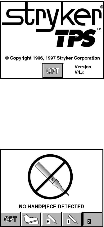
The Control Screen
This example shows that no handpiece is attached to the cord plugged into the TPS2 port.
TPS Start-Up Screen
This display appears on the screen every time the console is turned on.
This display remains on the screen until a cord is plugged into one of the TPS handpiece ports or the OPT button is depressed.
If a handpiece cord is plugged into a handpiece port when the console is turned on, this display shows momentarily before changing to either a no handpiece detected screen or to the screen of the selected handpiece.
No Handpiece Detected
Screen
This image indicates that no handpiece is attached to the cord plugged into the selected port. The screen will change to the handpiece screen when the missing handpiece is connected to the cord.
NOTE: This screen will also appear if the console is unable to recognize the handpiece. This could be
caused by a handpiece that is not compatible with the TPS console, or a faulty or damaged handpiece or cord.

Functions of the Control Screen
The TPS console allows the user to select functions and settings such as handpiece selection, speed, and direction. Designed to be easy to use and understand, the touch sensitive control screen allows you to set the system controls with the touch of a finger. Interactive icons on the control panel represent system components and functions. The control screen also provides important monitoring information for the selected handpiece.
Surgeon |
|
preference |
Handpiece power |
indicator |
Indicator ramp |
|
Attachment/ |
|
|
Handpiece |
Blade |
Handpiece |
|
identification |
identification |
||
speed |
|||
|
|
||
|
|
TPS handpiece |
|
|
|
select buttons |
|
|
Endo handpiece |
Select system |
Footswitch |
select button |
indicator and |
|
|
options screen |
|
|
options |
|
|
|
|
Elements of the Control Screen
Control screen visually presents options which can be set for the selected handpiece.
Icons represent elements of your TPS system. Icons are functional buttons. Each function may be selected by pressing the screen where the button is displayed. When you touch an icon, the icon appears to be pressed down and the graphic symbol highlights to indicate that it is activated. (See Icon Definition).
NOTE: An audible signal indicates interface with icons.
NOTE: Buttons such as the adjust arrows or OPT button which are temporary toggles or adjustment buttons only highlight while depressed.
NOTE: Buttons with a white background are toggle buttons.
NOTE: Options vary among different handpieces. The console will only display the options available for a given handpiece.
Handpiece identification displays the name of the active handpiece. NOTE: Handpieces can be plugged into each of the console's handpiece ports, but only one can be selected at a time.
NOTE: When *CUSTOM* is displayed at the top of the screen, the console's default settings are selected from Surgeon Preferences. The console is able to capture the preferred settings for several different users. When this feature is activated, the preferred settings act as default settings. See Surgeon Preference for further details.
Handpiece speed information displays the default speed for each handpiece until you reset speed settings.
While the handpiece is running, the display shows the actual handpiece speed. If the handpiece is not running the default or selected speed is displayed.
NOTE: Incremental information displayed on the control screen is accurate within +/-1%.
Select Your System Settings
NOTE: When the console is turned on, its default setting is factory default unless a Surgeon Preference setting is
selected as the start up default. See Surgeon Preference for further details.
1.Handpiece select buttons enable you to activate the handpiece plugged into one of the three ports on the front of the console. To display the control screen for the handpiece plugged into the TPS1 port, touch the
corresponding handpiece select icon. The icon highlights and appears pressed down.
NOTE: Selecting a handpiece icon activates the corresponding handpiece and displays its specific control screen.
2.Change the maximum handpiece speed. Press the adjustment arrows to change the handpiece speed setting incrementally until the desired speed is reached.
•Saws - The set point is displayed as a percentage of maximum power and vertical line on the speed ramp. During handpiece operation, the percentage reading and speed ramp displays the power level.
•Rotary handpieces - The speed set point is displayed. During handpiece operation, the current speed is displayed.
3.Select various settings as desired. Refer to the control screens on the following pages for details for each handpiece.
4.Select the OPT icon to access the MAIN OPTION screen.
This screen allows access to general console and user settings as well as direct access to each handpiece option screen.
NOTE: The screen returns to the active handpiece adjustments screen when the handpiece name is touched.
5.Touch the EXIT icon to return to the active handpiece control screen.
Standard Features
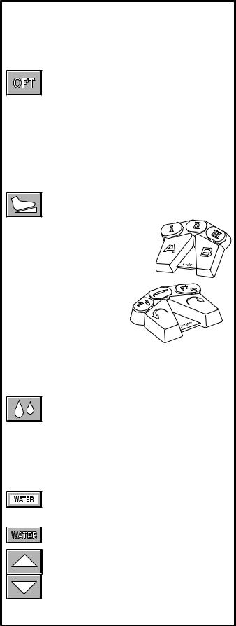
Main Option Icon
The option icon appears on all handpiece screens and allows access to the MAIN OPTION screen. See MAIN OPTION SCREEN for further details.
Footswitch Icon
The footswitch icon only appears when a footswitch is plugged into the console.
If using a footswitch with these graphics, pedal functions can be reprogrammed. See Footswitch Adjustments and Footswitch Button Mapping.
A footswitch with these graphics cannot be reprogrammed.
Handpiece Irrigation
Irrigation functions pertain only to Irrigation Console REF 5100-50.
Press the icon to start irrigation flow while the handpiece is running.
If irrigation is desired while the handpiece is stopped, press and hold the icon until the pump is activated. The pump can be turned off by touching the icon again.
Irrigation flow rate can be adjusted from the HANDPIECE screen or the HANDPIECE ADJUSTMENTS screen.
From the HANDPIECE screen, toggle the SPEED icon to WATER before using the arrows to adjust
flow rate.
-OR-
From the HANDPIECE ADJUSTMENTS screen, select the WATER icon and use the arrows to adjust flow rate. Flow rate diminishes as the setting approaches zero.
NOTE: Flow rate may vary among handpiece models.
The pump can also be turned on and off with the footswitch.
10
Loading...