


Booms and Lights
Installation and Service Manual
July 2011 |
1004-400-061 REV YB |
www.stryker.com |
Stryker Booms and Lights
Installation and Service Manual
This manual contains confidential information that shall not be disclosed or duplicated for any reason other than to use and maintain a Stryker Booms and Lights. This restriction does not limit the right to use information contained in this manual, if it is obtained from another source without restriction. The information subject to this restriction is contained in all pages of this manual.
© June 2011 Stryker Communications. All rights reserved. Information in this document is subject to change without notice. Stryker, Stryker logo, Visum®, and StrykeCam® 2 are registered trademarks of Stryker
All rights reserved.
Stryker Booms and Lights Installation and Service Manual 1004-400-061 REV YB


|
|
|
S |
|
|
Contents |
|
1. Warnings and Cautions........................................................................................................................................ |
10 |
||
1.1 |
Safeguards and Precautions............................................................................................... |
10 |
|
1.2 |
Warnings........................................................................................................................... |
10 |
|
2. Product Symbol Definition................................................................................................................................... |
11 |
||
3. Tool List................................................................................................................................................................ |
|
|
13 |
3.1 |
Required Tools................................................................................................................... |
13 |
|
3.2 |
Optional Tools.................................................................................................................... |
13 |
|
4. Unpacking............................................................................................................................................................ |
|
|
14 |
4.1 |
Halogen Light.................................................................................................................... |
14 |
|
4.1.1 |
Suspension Box......................................................................................................... |
14 |
|
4.1.2 |
Accessory Box............................................................................................................ |
14 |
|
4.1.3 |
Light Head Boxes....................................................................................................... |
14 |
|
4.2 |
LED Light........................................................................................................................... |
15 |
|
4.2.1 |
Suspension Box......................................................................................................... |
16 |
|
4.2.2 |
Accessory Box ........................................................................................................... |
16 |
|
4.2.3 |
Light Head Boxes 1 and 2............................................................................................ |
16 |
|
4.3 |
Flat Panel Arms ................................................................................................................. |
17 |
|
4.4 |
Booms............................................................................................................................... |
17 |
|
5. Preparing the Mounting (Interface) Plate............................................................................................................ |
18 |
||
6. Preparing the Suspensions................................................................................................................................... |
19 |
||
6.1 |
Installing the Cable Kit for Lights........................................................................................ |
19 |
|
6.2 |
Surgical Lights................................................................................................................... |
20 |
|
6.2.1 |
Standard Horizontal Arm............................................................................................ |
20 |
|
6.2.2 |
Extended Horizontal Arm........................................................................................... |
20 |
|
6.2.3 |
Alternate Light Installation Instructions..................................................................... |
21 |
|
6.3 |
Flat Panel.......................................................................................................................... |
22 |
|
6.4 |
Booms............................................................................................................................... |
22 |
|
6.5 |
Routing Cables................................................................................................................... |
24 |
|
7. Installing the Suspension and Boom Arms........................................................................................................... |
25 |
||
7.1 |
Alternate Light Installation Instructions (Continued)........................................................... |
26 |
|
5

S
8. Installing Light Heads.......................................................................................................................................... |
27 |
||
8.1 |
LED and Halogen................................................................................................................ |
27 |
|
8.1.1 |
Standard Light.......................................................................................................... |
27 |
|
8.1.2 |
Low Ceiling Light....................................................................................................... |
28 |
|
9. Powering the System........................................................................................................................................... |
31 |
||
9.1 |
Halogen Lights.................................................................................................................. |
31 |
|
9.1.1 |
Electrical and Data Connections.................................................................................. |
31 |
|
9.2 |
LED Lights......................................................................................................................... |
32 |
|
9.2.1 |
Power Supply Box Wall Mount (Optional)..................................................................... |
32 |
|
9.3 |
Power Supply Box Connections........................................................................................... |
33 |
|
9.3.1 |
Power....................................................................................................................... |
34 |
|
9.3.2 |
Control...................................................................................................................... |
34 |
|
9.3.3 |
Wall Control Unit Port ................................................................................................ |
35 |
|
9.3.4 |
SORN......................................................................................................................... |
35 |
|
9.3.5 |
SIDNE........................................................................................................................ |
35 |
|
9.3.6 |
Expansion Port (Optional)........................................................................................... |
35 |
|
9.4 |
Visum LED New Installation Setup....................................................................................... |
36 |
|
9.4.1 |
Required Tools........................................................................................................... |
36 |
|
9.4.2 |
Installing USB to RS-232 Adapter (for laptops without Serial Ports)............................... |
36 |
|
9.4.3 |
Connecting a Laptop to the SIDNE Port on Visum LED System........................................ |
37 |
|
9.4.4 |
Visum LED Main Menu................................................................................................ |
39 |
|
9.4.5 |
New Installation........................................................................................................ |
39 |
|
10. Monitor Assembly.............................................................................................................................................. |
40 |
||
10.1 Light Flat Panel or Single Panel installation ........................................................................ |
40 |
||
10.2 |
Adjusting the Yoke............................................................................................................. |
41 |
|
10.2.1 |
Adjusting the Width................................................................................................... |
41 |
|
10.2.2 |
Adjusting the Height.................................................................................................. |
45 |
|
10.3 |
Attaching the Monitor........................................................................................................ |
46 |
|
10.4 |
Balancing the Monitor........................................................................................................ |
48 |
|
10.5 |
Adjusting the Brakes.......................................................................................................... |
50 |
|
11. Boom Shelf Attachment and Adjusting Brakes/Stops........................................................................................ |
51 |
||
11.1 Boom Shelf and Accessories Attachment.............................................................................. |
51 |
||
11.1.1 |
FLEXiS Shelf Installation............................................................................................. |
51 |
|
6

|
|
S |
11.1.2 |
FLEXiS Handle to MFR Bracket Installation ................................................................... |
54 |
11.1.3 |
FLEXiS Handle to Service Head Installation .................................................................. |
56 |
11.1.4 |
Installing Auxiliary Plates .......................................................................................... |
58 |
11.1.5 |
Installing Other Accessories ........................................................................................ |
59 |
11.1.6 |
Installing GCX Accessory Track on OSC600 Down Tube ................................................... |
59 |
11.1.7 |
Drawer Installation .................................................................................................... |
59 |
11.2 |
Lights and Flat Panel Arms ................................................................................................. |
60 |
11.2.1 |
Height Adjustment .................................................................................................... |
60 |
11.2.2 |
Tension Adjustment ................................................................................................... |
62 |
11.2.3 |
Adjusting the Friction Brakes ...................................................................................... |
62 |
11.2.4 |
Adjusting the Brake Force of the Extension and Spring Arms ......................................... |
64 |
11.2.5 |
Adjusting Down Tube Screws ...................................................................................... |
64 |
11.3 |
Adjusting the Cardanic Suspension ..................................................................................... |
66 |
11.4 |
Boom Arms ........................................................................................................................ |
67 |
11.4.1 |
OSC400 ...................................................................................................................... |
67 |
11.4.2 |
OSC600 ...................................................................................................................... |
70 |
12. Installing Covers |
................................................................................................................................................. |
72 |
12.1 |
Lights and Flat Panel Suspension ........................................................................................ |
72 |
12.2 |
Booms ............................................................................................................................... |
72 |
12.3 |
Tandem ............................................................................................................................. |
73 |
12.4 |
Cable ...................................................................................................................... Covers |
75 |
12.4.1 .............................................................................. |
Flat Panel/Light/Light Suspension |
75 |
12.4.2 ........................................................ |
Light/Flat Panel Suspension - Teacup Installation |
75 |
12.4.3 .................................................................................... |
MMP200, OSC400, and OSC600 |
76 |
12.4.4 ...................................................................................... |
Mounting Motor Ring Covers |
77 |
12.4.5 ........................................................................ |
Replacing Rear End Spring Arm Covers |
77 |
12.5 |
Installing .............................................................. a Flexstrip Kit (Dual Flat Panel Arm Only) |
78 |
13. Accessories |
|
79 |
13.1 |
Lights ................................................................................................................................ |
79 |
13.1.1 ................................. |
Halogen In - Light Camera and Weighted Light Handle Assemblies |
79 |
13.1.2 ........................................ |
LED In - Light Camera and Weighted Light Handle Assemblies |
79 |
13.1.3 ............................................................. |
Field Upgrade for StrykeCam In - Light Camera |
79 |
13.1.4 .................................................................................. |
Power Supply Box Components |
81 |
13.1.5 ................................................................................................... |
Camera Installation |
82 |
7

S
14. Legacy................................................................................................................................................................ |
|
|
84 |
14.1 |
Suspension Installation...................................................................................................... |
84 |
|
14.2 |
Installing Spring Arms (if necessary for lights only suspension)............................................. |
84 |
|
14.3 |
Standard Width Yoke.......................................................................................................... |
87 |
|
14.4 |
Halogen Light Flat Panel Stop Replacement........................................................................ |
87 |
|
14.5 |
Variant.............................................................................................................................. |
89 |
|
14.6 |
Installing GCX Accessory Track on OSC400 Service Head......................................................... |
89 |
|
15. Cleaning and Completion................................................................................................................................... |
93 |
||
16. Servicing the Visum 600/450............................................................................................................................. |
94 |
||
16.1 |
Electronic Control System................................................................................................... |
94 |
|
16.2 |
Power Supply Box.............................................................................................................. |
96 |
|
16.2.1 |
Halogen Power Supply Box Troubleshooting Guide ...................................................... |
96 |
|
16.3 |
Wall Control...................................................................................................................... |
99 |
|
16.4 |
Plug Layout of the Electronic Control System..................................................................... |
101 |
|
16.5 |
Plug Allocation................................................................................................................ |
101 |
|
16.5.1 |
Location of the Plug and Diagnostic LEDs on the Terminal .......................................... |
102 |
|
16.5.2 |
Plug Allocation Operating Console and Diagnostic LEDs .............................................. |
103 |
|
16.5.3 |
Plug Locations of the Power Box ............................................................................... |
103 |
|
16.5.4 |
Connections at the front: ......................................................................................... |
104 |
|
16.5.5 |
Connections at the back: .......................................................................................... |
105 |
|
16.5.6 |
Connection Structure of Systems .............................................................................. |
107 |
|
16.6 |
Can Bus Troubleshooting.................................................................................................. |
110 |
|
16.6.1 |
Light Block Diagram ................................................................................................. |
110 |
|
17. Servicing Booms |
.............................................................................................................................................. |
114 |
|
17.1 |
System ............................................................................................................operation |
114 |
|
17.2 |
Troubleshooting.............................................................................................................. |
114 |
|
17.2.1 ................................................................................................................. |
Air Leaks |
115 |
|
17.3 |
Miscellaneous ...................................................................................Hardware Parts List |
117 |
|
17.4 |
Replacing ..................................................................................................the Trim Strip |
119 |
|
17.5 |
Replacing ...........................................................................................................Med Gas |
120 |
|
17.5.1 ................................................................................ |
Replacing a Nitrogen Regulator |
120 |
|
17.5.2 .......................................................................................... |
Replacing Med Gas Plate |
120 |
|
8

|
|
|
S |
17.6 |
Replacing the Brake Bladder............................................................................................. |
121 |
|
17.7 |
Reassembling the Service Head........................................................................................ |
127 |
|
17.7.1 |
Removing and Attaching the Front and Back Plates ................................................... |
127 |
|
17.7.2 |
Removing and Attaching the MFR ............................................................................. |
128 |
|
17.7.3 |
Removing Extrusions ............................................................................................... |
129 |
|
17.7.4 |
Installing Extrusions ................................................................................................ |
129 |
|
17.7.5 |
Removing Modules .................................................................................................. |
130 |
|
17.7.6 |
Installing Modules ................................................................................................... |
132 |
|
17.8 |
Replacing the Motor......................................................................................................... |
133 |
|
17.9 |
Electro-Pneumatic (EP) Module......................................................................................... |
135 |
|
17.9.1 |
Removing the Electro - Pneumatic (EP) Module ........................................................... |
135 |
|
17.9.2 |
Installing an Electro - Pneumatic (EP) Module ............................................................. |
135 |
|
17.10 Generation 1 Service Head................................................................................................ |
136 |
||
17.10.1 |
Replacing a Shelf with Brake .................................................................................... |
136 |
|
17.10.2 |
Replacing the Brake Button ...................................................................................... |
138 |
|
18. Servicing the LED |
............................................................................................................................................. |
140 |
|
19. Replacement Part .............................................................................................................................Numbers |
141 |
||
20. Contact Information......................................................................................................................................... |
144 |
||
9
S
1. Warnings and Cautions
Please read this manual and follow its instructions carefully. The words WARNING, CAUTION, and Note carry special meanings and should be carefully reviewed:
Warning |
The personal safety of service personnel may be involved. Disregarding |
|
this information could result in injury to the patient. |
Caution |
Special service procedures or precautions must be followed to avoid dam- |
|
aging the equipment. |
Warning |
A warning with a lightening bolt warns of hazardous voltage. All service |
|
must be performed by authorized personnel. |
Note |
Special information to make maintenance easier or important information more |
|
clear. |
1.1Safeguards and Precautions
Stryker trained personnel are the only personnel authorized to install the equipment described in this manual.
Incorrect operation or negligence of safety measures may cause damage to the equipment, bodily injury or death. Thoroughly read this manual before use.
•Do not add additional weight to the surgical lights.
•Do not place anything over the surgical lights.
•Do not look directly into the surgical light while powered on.
1.2Warnings
1.Be a qualified/trained installer for this equipment.
2.Test this equipment prior to release for use by hospital personnel.
3.Disconnect the unit from the electric outlet before inspecting or servicing system components. Note that more than one electrical supply may be used. Disconnect all power sources before inspecting.
4.The electrical installation of the operating room must comply with any applicable IEC, CEC, NEC requirements as well as the local codes and pre-installation manual.
Caution |
Carefully unpack the unit and check to ensure that no damage occurred |
|
during shipment. If damage has occurred, please contact Stryker Commu- |
|
nications. |
10
S
2. Product Symbol Definition
The following symbols may be found on the Stryker Booms and Lights equipment:
|
An exclamation mark within a triangle is intended to alert the user to the presence |
|
|
of important operating and maintenance (service) instructions in the literature ac- |
|
|
companying the product. |
|
|
A lightning bolt within a triangle indicates the presence of hazardous voltage. Refer |
|
|
all service to authorized personnel. |
|
|
|
|
|
Denotes usage tips and useful information. |
|
|
|
|
|
Denotes compliance to European Community Directive 93-42-EEC. |
|
|
|
|
|
Indicates the product is compliant “Medical Electrical Equipment with Respect to |
|
EDS |
Electrical Shock, Fire, and Mechanical Hazard only in accordance with UL60601-1. |
|
|
||
(29AZ) |
|
|
|
Indicates the product is compliant “Medical Electrical Equipment with Respect to |
|
EDS |
Electrical Shock, Fire, and Mechanical Hazard only in accordance with CAN/CSA |
|
C22.2 No601.1. |
||
(29AZ) |
||
|
Indicates the product is compliant “Medical Electrical Equipment with Respect to |
|
|
Electrical Shock, Fire, and Mechanical Hazard only in accordance with UL60601-1, |
|
(13PZ) |
CAN/CSA C22.2 No601.1. |
|
|
||
|
Indicates hot surfaces. |
|
|
|
|
|
Denotes compliance to CSA Standard C22.2, 60601.1 - M90, AS 3200, IEC 60601, |
|
|
IEC 60601-2-41, UL 60601, EN 60601 |
|
|
|
|
|
Denotes the date the equipment was manufactured. |
|
|
|
|
|
Denotes the manufacturer of the device. |
|
|
|
|
|
A yellow box with a hand within a triangle is intended to warn the user of the pres- |
|
|
ence of an electrostatic sensitive device. Follow ESD prevention procedures. |
|
|
|
|
|
Denotes product/part number. |
|
|
|
|
|
Denotes product/serial number. |
|
|
|
|
|
Denotes lot or batch number. |
|
|
|
|
|
The acceptable wattage input range for this product. |
|
|
|
11
S
In accordance with European Community Directive 2002/96/EC on Waste Electrical and Electronic Equipment, this symbol indicates that the product must not be disposed of as unsorted municipal waste but should be collected separately.
Note: The device does not contain any hazardous materials.
Legal regulations may include specifications regarding the disposal of this product. We request that you contact Stryker when you plan to withdraw this device from service for discard.
12

S
3. Tool List
3.1Required Tools
•Genie lift or equipment lift, SLC-12 or equivalent
•Torpedo level
•Metric allen set (Shortened 3mm)
•Small and large phillips head
•Small and Large flat head screwdriver
•24mm (15/16 inch) wrench
•Snap ring plier (adjustable to 15mm)
•Torque Wrench (in. lbs.)
•Torque Wrench (ft. lbs.)
3.2Optional Tools
•Porta band saw
•Large hand file
•1/2 inch Drill/Driver
•Tape measure
•Drill bit set
•Hand tool pouch
•Adjustable wrench
•Roofer’s square
13
S
4. Unpacking
4.1Halogen Light
Warning |
Use caution when lifting heavy objects to avoid serious bodily injury or |
|
damage to the equipment. |
The equipment will arrive in shipping boxes on two separate pallets and may be arranged as depicted in the images below. The shipping boxes should contain all the necessary components required to install the halogen light system. Use the image and list below to determine where each component of the light suspension is packaged.
|
Down Tubes |
|
Ceiling |
|
|
|
|
|
Covers |
|
|
|
|
|
|
|
|
|
|
|
|
|
|
|
|
|
|
|
Suspension |
|
|
|
Accessory Box |
|
|
|
|
|
Light Head |
||
|
|
|
|
|
|
|
|
|
|
|
|
|
|
|
|
|
|
|
|
Light Head |
|
|
|
|
|
||
|
|
|
|
|
|
|
|
Suspension |
|
|
|
Light Head |
|
|
|
|
|
|
||
|
|
|
|
|
|
Light Head |
|
|
|
|
|
|
|
|
Pallet |
|
|
|
Pallet |
|
4.1.1Suspension Box
•Light Suspension
• Suspension (Single, Dual, or Triple)
• Spring Arms
• Installation Hardware
• Flat Panel Cable Kit
4.1.2Accessory Box
•Wall Control Unit and Cable Kits
•Power Supply Box
4.1.3Light Head Boxes
•Halogen light heads
•Light Handle Assemblies
•StrykeCam® In-Light Camera (if purchased)
•Sterilizable Light Handle
•Sterilizable Camera Handle (if StrykeCam was ordered)
If any parts are missing, contact the Shipping and Receiving Department to verify whether a shipping box(es) was left behind. If all boxes were delivered and parts are unaccounted for, call and inform your Project Manager of the missing items.
14
S
Use box cutters to open the shipping box along the seams.
 Note Notice that the boxes have “break away” panels to allow easy access to the parts.
Verify that all parts are present and visibly undamaged.
4.2LED Light
Warning |
Use caution when lifting heavy objects to avoid serious bodily injury or |
|
damage to the equipment. |
The equipment will arrive in shipping boxes and may be arranged as depicted in the image below. The shipping boxes should contain all the necessary components required to install the Visum® LED light system. Use the image and list below to determine where each component of the light suspension is packaged.
Light Head |
Light Head |
|
|
Light Head |
Light Head |
|
|
Suspension |
Accessory Box |
Suspension |
Accessory Box |
Pallet
*The outlined boxes represent a double shipment of supplies. Orientation of packaging may arrive differently.
15
S
Accessory Box |
|
Accessory Box |
|
|
|
Light Head |
|
Light Head |
|
|
|
Light Head |
|
Light Head |
|
|
|
|
Suspension |
|
|
|
|
|
Suspension |
|
|
|
|
|
Pallet |
|
4.2.1Suspension Box
•Light Suspension
• Suspension (Single, Dual, or Triple)
• Spring Arms
• Installation Hardware
• Flat Panel Cable Kit
• Tea Cup (EHA only)
4.2.2Accessory Box
(There are three boxes within the Accessory Box)
•Ceiling Cover (Box 1)
•Wall Control Unit and Light Cable Kits (Box 2)
•Power Supply Box and Bezel (Box 3)
•Down Tube
Extended Horizontal Arm Packaging
4.2.3Light Head Boxes 1 and 2
•LED light heads
•Light Handle Assemblies
•StrykeCam® 2 In-Light Camera (if purchased)
•Sterilizable Light Handle
•Sterilizable Camera Handle (if StrykeCam 2 was ordered)
16

S
If any parts are missing, contact the Shipping and Receiving Department to verify whether a shipping box(es) was left behind. If all boxes were delivered and parts are unaccounted for, call and inform your Project Manager of the missing items.
Use box cutters to open the shipping box along the seams.
 Note Notice that the boxes have “break away” panels to allow easy access to the parts.
Verify that all parts are present and visibly undamaged.
4.3Flat Panel Arms
The equipment will arrive in a shipping box on one pallet. The shipping box should contain the Flat Panel Arm System and Ceiling Covers.
The Flat Panel Arm will be fully assembled and completely wired out of the crate. Uncrate pallet and open the shipping box.
Use box cutters to open the shipping box along the seams. Verify that all parts are present and visibly undamaged.
4.4Booms
Each Boom will arrive in a shipping box on one pallet. The shipping box should contain a Boom Arm, Service Head, shelves (if applicable), and Ceiling Covers.
Use box cutters to open the shipping box along the seams. Verify that all parts are present and visibly undamaged.
17
S
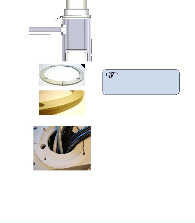
5. Preparing the Mounting (Interface) Plate
Remove the hardware bag from the suspension box.
Note Ensure all-thread rods do not interfere with the application of ceiling cover by performing a dry fit. The all-thread rods should not extend below the base of the cover. If they do, cut the rods back.
1. Install six hex nuts below Mounting (Interface) Plate to align flange top approximately even with the bottom of finished ceiling.
2. Use a Torpedo Level to verify that the nuts are level. Measure two sets at a time.
3.Place flat washers and Plastic Isolation Discs (required in Europe) below each hex nut to hold in place.
 Note Plastic Isolation Discs are only required in Europe.
Caution No more than 8 inches of exposed all-thread rod is allowed between the Preinstallation Plate and the down tube flange for Seismic considerations. No more than 2 inches of exposed all-thread rod is allowed for Zone 4 installations.
Cover Size
180 mm (7 inches) |
153 mm (6 inches) |
80 mm (3 inches) |
64 mm (2.5 inches) |
18
S
6.Preparing the Suspensions
6.1Installing the Cable Kit for Lights
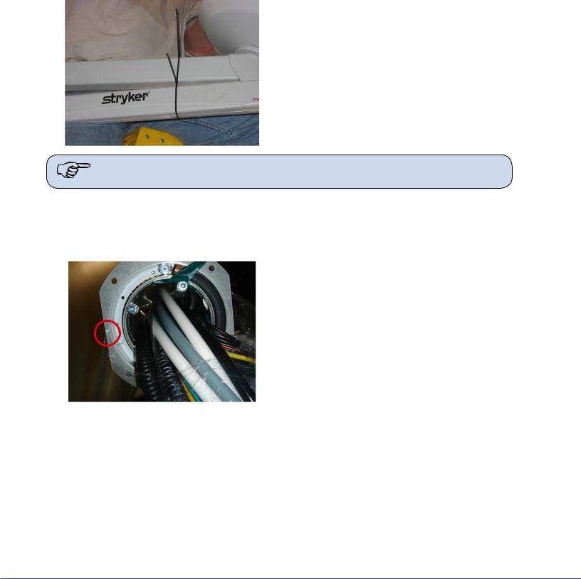
1.Route the power and control cables between the power supply box and the suspension structure. Verify that the light connectors remain near the ceiling plate, as shown in the figure below.
2.(For LED only) Route the S-Video cable through the pre-installed conduit between the super structure and video output location.
Note Consult your Project Engineer and/or room drawings to determine the video output location.
3.Pull the cable between the wall control unit and the power supply box. One end of the wall control unit cable is unterminated.
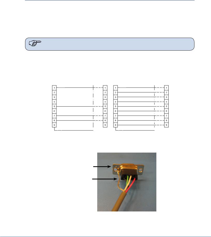
4.Cut the wall control unit cable to length and terminate it. Connect the wires into the female connector according to the schematic chart shown below.
P1 |
Schematic |
P2 |
P1 |
Schematic |
P2 |
|
|
RED
BLK
WHT
GRN
SHLD |
SHLD |
Wall Control Unit Cable Pin Configuration - LED (left) Halogen (right)
5. Solder the Shield Conductor to the DB9 female connector chassis as shown below.
DB9 Female
Connector
Shield Conductor
Soldered Shield Conductor
19
S
6.2Surgical Lights
6.2.1Standard Horizontal Arm
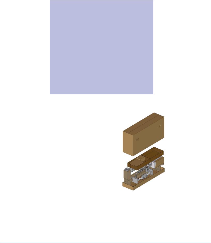
1.Load the suspension shipping box onto a heavy machinery lift device.
2.Cut cardboard 9 inches from the top of the box to facilitate hanging suspension. Be careful not to cut cables or scratch the suspension.
3.Mount down tube onto suspension. Use the six flat head socket cap screws (taped to down tube) to attach the down tube to the central axis spindle. Tighten all screws with a torque wrench set to 100 lb-in (8.33 lb-ft, 11.3 Nm). Once all screws have been tightened, retighten each screw to ensure correct torque is set.
If you are installing a flat panel along with a dual light suspension, verify that the flat panel cable kit is routed through the opening in the down tube.
4.Position the suspension assembly directly below the mount site.
5.Go to Section 7, “Installing the Suspension” to complete installation.
6.2.2Extended Horizontal Arm
1.Remove all accessories and the cardboard box.
2.Position Genie Life so that forks are underneath the highlighted areas shown in the following figure.
Brown packaging is wood
3.Mount down tube onto suspension. Use the six socket cap screws to attach the down tube to the central axis spindle. Tighten all screws with a torque wrench set to 354 lb-in (29.5 lb-ft, 40 N-m). Once all screws have been tightened, retighten each screw to ensure correct torque is set.
If you are installing a flat panel along with a dual light suspension, verify that the flat panel cable kit is routed through the opening in the down tube.
4.Position the suspension assembly directly below the mount site.
White packaging is styrofoam
20
S
6.2.3Alternate Light Installation Instructions
1.Load the suspension shipping box onto a heavy machinery lift device.
2.Cut cardboard 9 inches from the top of the box to facilitate hanging suspension. Be careful not to cut cables or scratch the suspension.
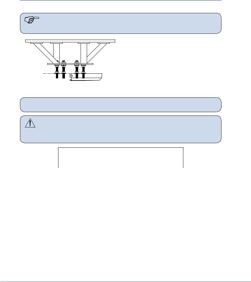
Hex Nut
Flat Washer

Lock Washer
Hex Nut
Note When necessary, Plastic Isolation Discs surround the mounting plate, but are only required in Europe.
3.Raise the down tube toward the mount site.
4.Guide the all-thread rods through the holes located on the down tube flange. The down tube flange must press lightly against the hardware assembly.
5.Place a flat washer on alternating all-thread rods followed by a hex nut; tighten the hex nut.
6.Use a Torpedo Level to verify the down tube flange is level across three horizontal planes. If the flange is not level, adjust the hex nuts until the Torpedo Level indicates the down tube flange is level across three horizontal planes. Confirm that the down tube is also level by placing the Torpedo Level on the down tube at three, evenly-spaced locations.
7. Install a flat washer, lock washer, and hex nut on the remaining all-thread rods.  Note Plastic Isolation Discs are only required in Europe.
8.Tighten the hex nuts to 75 ft-lbs. Ensure the lock washers are fully compressed.
9.Remove the hex nuts from the all-thread rods applied in step 5 and install a lock washer and hex nut.
21
S
10.Use a Torpedo Level to verify that the down tube flange is level across three horizontal planes.
11.Connect the ground wire (found on the down tube flange) to the ground lug located in the ceiling.
12.Refer to Section 7 to complete installation.
6.3Flat Panel
1.Place the suspension onto a heavy machinery lift device.
2.Use zip ties to tie the horizontal arm and Spring Arm together to prevent swinging during installation.
3.Raise the Flat Panel Arm for installation; position the arm so the stop is in the specified location (the Project Manager should have this information).
Note The normal stop position is above the bed, allowing 330° of rotation of the upper arm, with the 30° “dead” spot.
6.4Booms
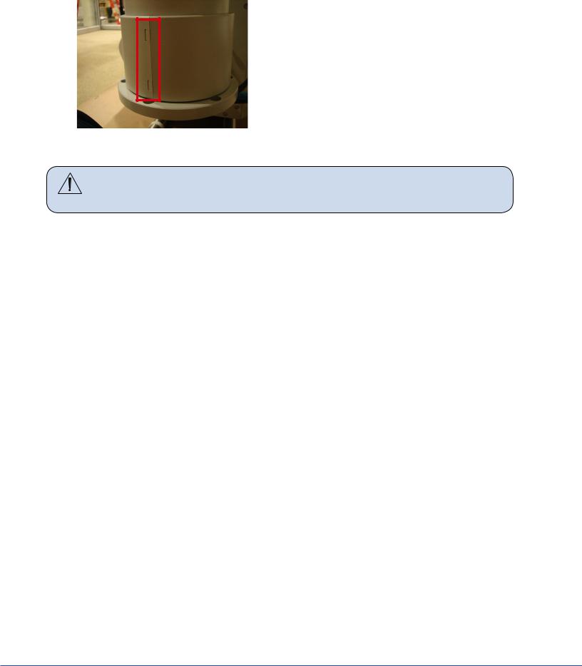
Due to door entry height, the flange and drop tube may be removed for entry into the room. The flange and drop tube must be reinstalled before installation of the equipment boom.
If the MMP200/OSC600 Service Head is not assembled:
1. Place pallet securely on material lift (e.g., Genie Lift).
2. Determine the orientation of the service head before attaching to the down tube, feel for the notch. The notch will be mounted to the front of the service Head.
22
S
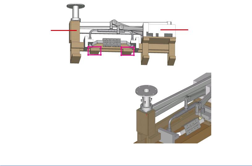
3. Remove the four Allen screws from the Service Head using a 5mm Allen wrench.
4. Locate the cable kit end and pass through
the service head opening.
Shelf End
MMP200 only
Note The Shelf Wedge kit has a thick and a thin component. Orientation of the thin side towards the front of the service head is important.
5. Verify which Wedge is the thinner wedge of the 2 halves of the Wedge Kit
6. Place the thinner Wedge towards the front of the Service Head
0682-001-345 Wedge Kit
7. Place the thicker Wedge towards the rear of the Service Head.
8. Connect Service Head to articulating arm.
9. Tighten the four Allen screws to 14.75 lb-ft (20 Nm) using a 5mm Allen wrench.
10. s
If the OSC400 Service Head is not assembled:
23
S
1. Remove the six (6) Allen screws from the Service Head using a 5mm Allen wrench.
2. Remove the cylinder cover located on the Down Tube. The two (2) halves can be detached by depressing on the two (2) clips with a flat edge tool.
3. Rotate the Down Tube and determine the stop location. This point will be installed to the front of the service head.
4.Locate the cable kit end and pass through the service head opening. In some cases, half of the pass-thru plate will need to be removed to feed the cable kit completely through.
Caution |
Be sure to leave enough slack for the EP Module control cable within the |
|
arm set. Failure to do so may result in damage to the cable upon removal |
|
of the EP module. |
5.Attach the service head by inserting and tightening the six (6) Allen screws to 7.4 lb-ft (10 Nm) using a 5mm Allen wrench.
6.5Routing Cables
This section is only applicable to suspensions with lengthy cable kits.
1.Uncoil the cable kit.
2.Pull the cables from the suspension through the top of the mounting interface plate.
3.Continue to route the cable through the ceiling conduits. Consult your Project Engineer and/or room drawings to determine cable routing through the conduits.
24
S
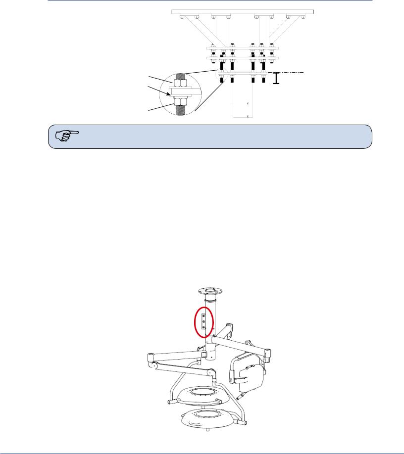
7. Installing the Suspension and Boom Arms
Hex Nut
Flat Washer

Lock Washer
Hex Nut
Note When necessary, Plastic Isolation Discs surround the mounting plate, but are only required in Europe.
1.Raise the Suspension assembly toward the mount site.
2.Take care when raising the suspension to prevent pinching cables between the all-thread rods and down tube.
3.Guide the all-thread rods through the holes located on the down tube flange. The down tube flange must press lightly against the hardware assembly.
4.Pull all cables and electrical connections through the Mounting (Interface) Plate. If ORIS connectivity is going to occur at a later date, tie-wrap cable kit to down tube flange.
5.Place a flat washer on alternating all-thread rods followed by a hex nut; tighten the hex nut.
6.Use a Torpedo Level to verify the down tube flange is level across three horizontal planes. If the flange is not level, adjust the hex nuts until the Torpedo Level indicates the down tube flange is level across three horizontal planes. Confirm that the down tube is also level by placing the Torpedo Level on the down tube at three, evenly-spaced locations.
25
S
7. Install a flat washer, lock washer, and hex nut on the remaining all-thread rods.  Note Plastic Isolation Discs are only required in Europe.
8.Tighten the hex nuts to 75 ft-lbs. Ensure the lock washers are fully compressed.
9.Remove the hex nuts from the all-thread rods applied in step 10 and install a lock washer and hex nut.
10.Use a Torpedo Level to verify that the down tube flange is level across three horizontal planes.
11.Connect the ground wire (found on the down tube flange) to the ground lug located in the ceiling.
12.Lower the lift device and check the suspension for stability.
13.Pull excess cable through conduit.
7.1Alternate Light Installation Instructions (Continued)
1.Using a lift device, raise the suspension into the down tube.
2.Pull all cables and electrical connections through the Mounting (Interface) Plate. If ORIS connectivity is going to occur at a later date, tie-wrap cable kit to down tube flange.
3.Pull excess cable through conduit.
4.Mount down tube onto suspension. Use the six flat head socket cap screws (taped to down tube) to attach the down tube to the central axis spindle. Tighten all screws with a torque wrench set to 100 lb-in (8.33 lb-ft, 11.3 Nm). Once all screws have been tightened, retighten each screw to ensure correct torque is set.
Note |
For EHA - Tighten all screws with a torque wrench set to 354 lb-in (29.5 lb-ft, 40 |
|
N-m). |
If you are installing a flat panel along with a dual light suspension, verify that the flat panel cable kit is routed through the opening in the down tube.
5.Take care when raising the suspension to prevent pinching cables between the down tube and suspension.
26
S
8. Installing Light Heads
8.1LED and Halogen
Always install the light heads before installing the light handle assembly and In-Light Camera. The camera light head must be installed on the uppermost Light Spring Arm.
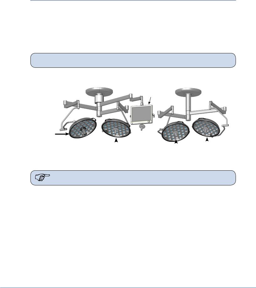
In the case of LED only, the physical difference between a 5-pole Spring Arm and a 9-pole Spring Arm is that the 5-pole slip ring is keyed and the 9-pole slip ring is not. The keys resemble rectangles when viewed from the end of the slip ring.
 Note Two people should lift the light head to attach it to the Spring Arm.
Triple Arm Visum |
Dual Arm Visum LED Light Suspension |
LED Light Suspension |
|
|
Monitor |
Light 1 w/
StrykeCam
Light |
|
2 |
|
4 |
Light |
|
3 |
|
|
|
|||||
|
|
|
|||||
|
Light |
Visum LED Light Suspension
Note StrykeCam 2 is always associated with Light 1 and is always installed above Light Head 2.
8.1.1Standard Light
8.1.1.15-Pole Light Head
1.Locate the 5-pole Spring Arm and remove the M3 screw.
2.Slide the Safety Segment Cover up to reveal the Safety Segment and re-insert the M3 screw to hold the cover up.
3.Remove the Safety Segment.
4.Install the 5-pole Light Head.
a.Align the top of the Cardanic Suspension with the bottom of the Spring Arm.
b.Align the rectangle-like keys along the outer wall of the 5-pole slip ring, (located in the light head) with the notches of the Spring Arm Slip Ring.
c.Raise the light head into the Spring Arm.
5.Reinstall the Safety Segment.
27
S
a.Remove the M3 screw and slide the Safety Segment Cover down.
b.Re-insert and tighten the M3 screw to keep the cover in place.
Warning |
Failure to tighten this screw can cause the Safety Segment Cover to slide |
|
and the light head to fall from the Spring Arm. |
8.1.1.29-Pole Light Head (LED Only)
1.Locate the 9-pole Spring Arm and remove the M3 screw.
2.Slide the Safety Segment Cover up to reveal the Safety Segment.
3.Remove the Safety Segment.
4.Align the top of the Cardanic Suspension with the bottom of the Spring Arm.
5.Install the 9-pole Light-Head.
 Note The 9-pole slip ring is not keyed.
6.Raise the light head into the Spring Arm.
7.Reinstall the Safety Segment.
a.Slide the Safety Segment Cover down.
b.Tighten the M3 screw to keep the cover in place.
Warning |
Failure to tighten this screw can cause the Safety Segment Cover to slide |
|
and the light head to fall from the Spring Arm. |
8.1.2Low Ceiling Light
8.1.2.1Low Ceiling 5-Pole Light Head
1.Locate the 5-pole Spring Arm and remove the brake screw.
Brake Screw
2.Rotate the cuff 90° to reveal the first retaining screw. Remove the retaining screw from the Spring Arm.
3.Rotate the cuff 180° to reveal the second retaining screw. Remove the retaining screw from the Spring Arm.
4.Install the 5-pole Light Head.
•Align the rectangle-like keys along the outer wall of the 5-pole slip ring (located in the light head) with the notches of the Spring Arm slip ring.
28
S
•Insert the light head into the Spring Arm. Make sure to support the Spring Arm when assembling.
5.Reinsert the retaining screws removed in steps 2 and 3.
 WARNING The cuff must be in place before installing the retaining screws.
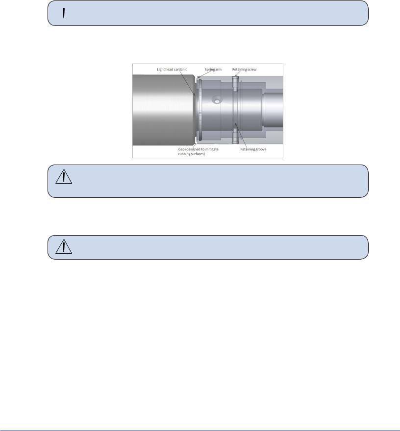
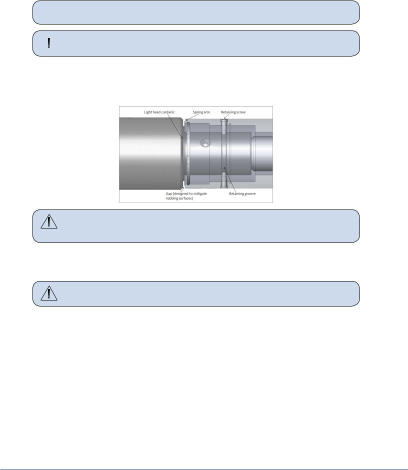
•Align the retaining ring groove feature on the Cardanic of the light head with the retaining screw holes in the spring arm. A gap will be present between the face of the Cardanic and face of the spring arm when properly aligned. If needed, back the light head out slightly.
Caution |
Tightening the retaining screws into the wall of the Cardanic without |
|
aligning them into the retaining ring groove may damage the surface of the |
|
Cardanic. |
•Place the first retaining screw through the opening of the cuff and reinstall it. Tighten the screw completely to ensure that the cuff will still rotate freely.
•Rotate the cuff 180° to reinstall the second retaining screw. Tighten completely.
Caution |
Over tightening the Low Ceiling light head to Spring Arm brake screw can |
|
cause permanent damage to the light |
•Rotate the cuff 90° to insert the brake screw back into place. Tighten the screw until the light head constantly holds the position in which it is placed.
•When adjusting the brake screw after installing the light for the first time or any time after performing preventative maintenance, adjust the brake screw and rotate the joint through a minimum of five rotations. If after five rotations the joint becomes difficult to rotate, the brake screw is over tightened and needs to be readjusted.
8.1.2.2Low Ceiling 9-Pole Light Head
1.Locate the 9-pole Spring Arm and remove the brake screw.
2.Rotate the cuff 90° to reveal the first retaining screw. Remove the retaining screw from the Spring Arm.
3.Rotate the cuff 180° to reveal the second retaining screw. Remove the retaining screw from the Spring Arm.
4.Install the 9-pole light head. Make sure to support the Spring Arm when assembling.
29
S
 Note The 9-pole slip ring is not keyed.
 WARNING The cuff must be in place before installing the retaining screws.
5.Reinsert the retaining screws removed in steps 2 and 3.
•Align the retaining ring groove feature on the Cardanic of the light head with the retaining screw holes in the spring arm. A gap will be present between the face of the Cardanic and face of the spring arm when properly aligned. If needed, back the light head out slightly.
Caution |
Tightening the retaining screws into the wall of the Cardanic without |
|
aligning them into the retaining ring groove may damage the surface of the |
|
Cardanic. |
•Place the first retaining screw through the opening of the cuff and reinstall it. Tighten the screw completely to ensure that the cuff will still rotate freely.
•Rotate the cuff 180° to reinstall the second retaining screw. Tighten completely.
Caution |
Over tightening the Low Ceiling light head to Spring Arm brake screw can |
|
cause permanent damage to the light |
•Rotate the cuff 90° to insert the brake screw back into place. Tighten the screw until the light head constantly holds the position in which it is placed.
•When adjusting the brake screw after installing the light for the first time or any time after performing preventative maintenance, adjust the brake screw and rotate the joint through a minimum of five rotations. If after five rotations the joint becomes difficult to rotate, the brake screw is over tightened and needs to be readjusted.
30
 Loading...