


SmartPump® Tourniquet System
Dual Channel Tourniquet Pump
REF 5920-011-000
Instructions For Use
US Patents 6,051,016; 6,475,228; 6,605,103 |
Software Version |
Additional US and foreign patents pending |
1.3x |
2007/04 5920-011-700 Rev - www.stryker.com

Table of Contents
PAGE
User/Patient Safety |
5 |
Indications |
5 |
Contraindications |
6 |
Possible Adverse Effects |
6 |
Precautions for Use |
7 |
Environment and Placement |
7 |
1 Introduction |
8 |
System Overview |
8 |
Features |
9 |
Convenient Preparation |
9 |
Ease of Operation |
9 |
Continuous, Real-time Monitoring |
9 |
Accessory Information* |
9 |
Power Options |
10 |
AC Power |
10 |
Internal Battery |
10 |
Low Battery Power Alarms |
11 |
Maintaining Internal Battery Charge |
11 |
2 Control Panel and Display |
12 |
Control Buttons |
13 |
Display Screen |
15 |
Display Indicators |
16 |
Status Indicators |
16 |
Alarm Indicators |
16 |
ii

3 Preparing for Use |
17 |
Mounting the SmartPump |
17 |
Power Requirements |
18 |
Initial Set-up |
18 |
Default Parameters |
19 |
Procedure Timer |
19 |
Target Pressure |
19 |
Changing Default Time and Pressure Settings |
20 |
4 General Use Procedure |
21 |
Connect the Cuff To Fill Line Connector |
21 |
Turn On the SmartPump |
22 |
Setting Timer and Target Pressure |
23 |
Time Display Format |
24 |
Alarm Volume Adjustment |
24 |
Default Display Viewing Preferences |
24 |
Setting Time and Date |
26 |
Cuff Inflation |
28 |
Intravenous Regional Anesthesia (IVRA) Lock |
28 |
To Inflate a Cuff |
28 |
Cuff Pressure Gauge |
29 |
Monitor Time and Pressure |
29 |
Cuff Deflation |
33 |
Tourniquet Report Printer |
34 |
Bier Block Procedure |
35 |
Responding to Alarms and Service Codes |
36 |
Service Codes |
36 |
Using the SmartPump’s Backup Capability |
37 |
iii

5 |
Cleaning and Maintenance |
39 |
|
Cleaning Recommendations |
39 |
|
Periodic Maintenance |
40 |
|
Annual Maintenance Checklist |
43 |
6 |
Service Code Summary |
46 |
7 |
Specifications |
47 |
iv

User/Patient Safety
WARNINGS:
This manual explains how to use the Stryker SmartPump® tourniquet system. Failure to follow the conditions of use set forth below shall absolve Stryker from any responsibility for the safety, reliability, and performance of this equipment:
♦Federal law restricts the sale of this device. It may be sold only by or on the order of a physician.
♦Only qualified medical personnel may use the SmartPump.
♦SmartPump users should read the Instructions For Use prior to operation.
♦To reduce the risk of electrical shock, DO NOT open the enclosure. Refer service to qualified service personnel.
♦Only personnel trained and/or authorized by Stryker may perform adjustments, modifications, or repairs to this equipment.
♦The SmartPump must be used, maintained and cleaned in accordance with these Instructions For Use.
Indications
A tourniquet is indicated when it is necessary to reduce blood flow and/or when greater visualization of the operating field is imperative or desired. It is designed to temporarily occlude or decrease blood flow in a patient’s extremities during surgical procedures of those extremities and is not a substitute for proper hemostasis. Typical procedures include:
♦Arthroscopy
♦Tendon repair
♦Total wrist joint repair
♦Knee joint replacement
♦Finger joint replacement
♦Nerve repair
♦Bone grafts
And other surgeries of the extremities identified by your institution requiring temporary occlusion of blood flow.
User/Patient Safety |
5 |

Contraindications
A tourniquet is not suitable for ligatures or cauterization to stop hemorrhages and should never be applied without consideration of the local anatomy. The Stryker SmartPump and associated tourniquet cuff is contraindicated for use on the torso.
Tourniquets are contraindicated for use on patients exhibiting unusual or complicated neurological or vascular problems of the extremities such as arteriovascular impairment, phlebitis, infection, uncontrolled diabetes, and/or other associated problems.
Current medical literature lists the following as possible contraindications:
♦Compromised vascular circulation
♦Severe scar tissue in cuff zone
♦Mellitus
♦Open leg fractures
♦Post traumatic lengthy reconstruction
♦Severe crushing injuries
♦Elbow surgery (associated with excessive swelling)
♦Severe hypertension
♦Skin grafts in which bleeding must be readily distinguished
♦Presence of sickle cell disease or clotting disorder
All final decisions regarding use of a tourniquet are the responsibility of the attending physician.
Possible Adverse Effects
WARNING: Excessive pressure or prolonged application could potentially cause:
♦Vascular complications
♦Neuromuscular or neurological injuries
♦Tourniquet pain
♦Ischemia
♦Venous emboli or thromboembolism
♦Blood vessel trauma
♦Reperfusion problems and arterial occlusion
♦Mild, aching pain may develop in the limb
♦Stiffness, weakness, reactive hyperemia, and skin discoloration
♦Death, specific to the Bier Block procedure
User/Patient Safety |
6 |

Precautions for Use
Extreme care must be taken when using tourniquets. Minimum cuff pressure and application time should be used. Monitor time and pressure throughout the procedure as injury may occur.
WARNINGS:
•Disconnect the deflated cuff from the fill line connector when a procedure is completed. Disconnecting a deflated cuff manages potential risks by:
(1)eliminating the risk of injury should a user unintentionally re-inflate a deflated, unmonitored cuff and (2) providing confirmation that the cuff deflation sequence has been implemented and completed. Failure to comply may result in patient injury.
•At the end of a procedure, as soon as the tourniquet pressure is released, remove the cuff, sleeve and other underlying materials, as the slightest impedance of venous return may lead to congestion and pooling of blood in the operative field. Failure to comply may result in patient injury.
Follow guidelines developed by your institution regarding standards of practice for tourniquet use. Failure to follow instructions could result in possible medical complications.
Published tourniquet guidelines and training programs developed by the Association of periOperative Registered Nurses (AORN) provide valuable references and resources to establish and update guidelines.
The AORN Recommended Practices for Use of The Pneumatic Tourniquet is available online. Originally published in the AORN Journal and revised in December 1998, it is included in the AORN 2000 Standards, Recommended Practices, and Guidelines.
AORN’s web address is www.aorn.org. The AORN mailing address is 2170 South Parker Rd, Suite 300, Denver, CO 80231.
Environment and Placement
WARNINGS:
♦The SmartPump is designed for use in a non-sterile zone of a surgical operating room. The SmartPump must be placed outside the patient zone, 6 feet [1.83 m] horizontally 8 feet [2.5 m] vertically.
♦For optimal use, the SmartPump, including the roll stand with pole, must be positioned and installed according to the instructions herein.
♦Use only hospital grade line cord connected to a hospital grade grounded receptacle.
♦Ensure power cord is away from personnel traffic and areas of water or liquids.
♦DO NOT place the SmartPump on an unstable cart, stand, or table. Recommend using the Stryker Roll Stand with pole REF 5920-013-000.
♦DO NOT use this equipment in the presence of a mixture consisting of flammable anesthetic and air or oxygen or nitrous oxide.
User/Patient Safety |
7 |
1 Introduction
System Overview
The SmartPump is a dual channel tourniquet pump. It is designed for use by qualified medical personnel to temporarily impede blood flow in a patient’s extremity in order to create a blood-free surgical zone.
Its dual channel design supports single cuff, bilateral and Bier Block procedures, and allows for simultaneous surgery of both an upper and lower limb. Each cuff’s unique pressure and time settings are displayed, controlled, and monitored independently. The SmartPump uses single port cuffs.
The built-in serial interface port supports its optional Stryker Tourniquet Report Printer and enables Clinical Information System (CIS) connectivity.
The two channels are identified on the SmartPump’s display as ‘Cuff 1’ and ’Cuff 2.’ The cuff connection ports are identified similarly.
Cuff 1 may be referred to as the ‘Main Cuff’ and Cuff 2 as the ‘Second Cuff.’
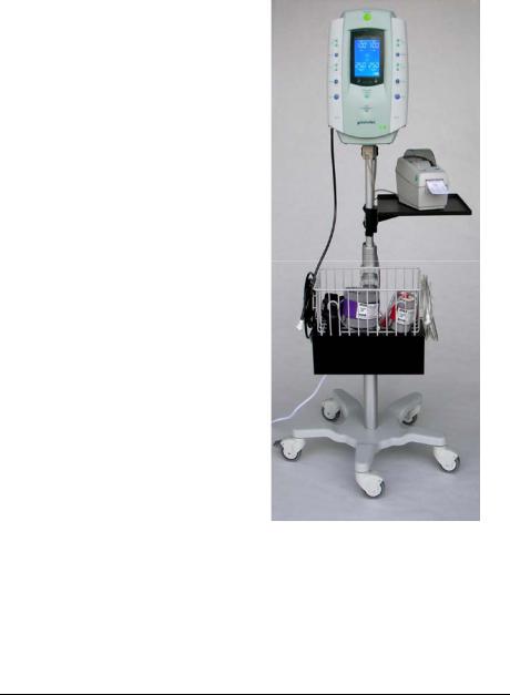
The SmartPump is shown with the recommended Stryker roll stand and cuff basket. The optional printer, printer tray and power cord organizer mounted below the basket are also shown.
Control Panel and Display |
8 |

Features
Convenient Preparation
♦The internal battery is charged automatically whenever the SmartPump is plugged into an AC power source. The internal battery is recharged to approximately 80% level within one hour.
♦The fully charged internal battery provides five hours of uninterrupted power. However, internal battery power is a safety feature and is to be used as a back up only. Always connect the SmartPump to an AC power source for normal operation.
♦Battery ‘saver’ technology keeps the internal battery charged. If the SmartPump is fully charged, then left ‘OFF(standby)’ and unplugged, the internal battery is kept charged for up to 30 days.
♦The SmartPump is center mounted to its recommended Stryker roll stand with pole.
♦Fill lines are attached to the positive locking connectors located at the bottom corners of the SmartPump.
♦At start-up, the SmartPump performs a self-test automatically and tests the pneumatic, pressure, display, battery, and processor systems. The SmartPump will alert the user via alarms, indicators and the display of error codes to assist in troubleshooting.
Ease of Operation
♦The procedure timer and cuff target pressure may be set using simple, intuitive steps. Control buttons are clearly identified.
♦Inflation is initiated by pressing the Inflate button.
♦Deflation is initiated by pressing and holding the Deflate button for 1.5 seconds.
Continuous, Real-time Monitoring
♦The large, bright, backlit LCD display shows total elapsed cuff inflation time and cuff pressure (mmHg). The displayed time format is user selectable: minutes or hours and minutes.
♦Audible control alarms and flashing graphical symbols identify conditions requiring attention.
Accessory Information*
Description |
REF |
Roll Stand with Pole …..…….………………………….…………..5920-013-000 Tubing, Stockinettes, Fill Lines, and Adapters .………………..5920-xxx-xxx Series Disposable Tourniquet Cuffs ………………………..….…………5921-xxx-xxx Series Non-sterile Reusable Tourniquet Cuffs…..…………….………..5922-xxx-xxx Series
*Contact your Stryker sales representative for a complete list of accessories.
Control Panel and Display |
9 |

Power Options
AC Power
The Smart Pump’s primary power source is AC power. As a safety feature, the SmartPump’s internal battery provides an alterative (back up) power source if AC power is lost.
Always connect the SmartPump to an AC power source for normal operation.
Internal Battery
The SmartPump’s internal battery automatically provides back-up power if AC power is interrupted. The internal battery when fully charged supports up to five hours of operation.
If, at initial start-up, the SmartPump is not plugged into AC power, the following occurs:
♦n o A C is displayed on the lower left of the LCD.
♦The Alarm Indicator Mute button flashes red.
Pressing the Alarm Indicator Mute button within 30 seconds of initial start-up will cancel the alarm. In this mode, the Alarm Indicator Mute button will return to green, the n o A C indicator will remain illuminated and the battery symbol will indicate the amount of battery charge.
NOTE: If, at initial start-up, there is no AC present and the Alarm Indicator Mute button is not pressed within 30 seconds, the SmartPump will return to its ‘OFF(standby)’ mode automatically. This feature prevents the SmartPump from unintentionally being used in a (back up) battery mode and prevents accidental battery discharge during transport and storage.
If AC power is interrupted during normal use, the SmartPump will use its internal battery automatically. Press the Alarm Indicator Mute button to acknowledge the change in power source. The Alarm Indicator Mute button returns to green.
When AC power is restored, the SmartPump will return to its normal AC operation automatically.
When the SmartPump is unplugged and turned ‘OFF(standby),’ it conserves its internal battery automatically using a power conservation mode. If fully charged, the internal battery is kept charged for up to 750 hours.
Control Panel and Display |
10 |
Low Battery Power Alarms
If a ‘low battery’ alarm condition occurs, connect the SmartPump to AC power as soon as possible. If AC power is unavailable and the internal battery becomes fully discharged, the SmartPump will maintain cuff pressure. Manual cuff deflation is required.
•If 30 minutes of internal battery operating time remain, the following will occur: an audible alarm, the Alarm Indicator Mute button will flash red and the battery charge icon will blink. The alarm may be muted for 15 minutes.
•If 15 minutes of internal battery operating time remain, an audible alarm will occur. The alarm may be muted for one minute, indicating the battery is ‘minutes’ from full discharge.
Maintaining Internal Battery Charge
When the SmartPump is plugged into AC power, its internal battery is charging automatically.
The SmartPump control panel indicates battery-charging status as follows:
Battery Charging Symbol: The segments of this symbol illuminates sequentially and repetitively while the internal battery is being charged. This occurs when the SmartPump is connected to an AC power source. Once the internal battery is fully charged, all of the segments are lit.
Battery Power Symbol: The segments of the battery power symbol are lit to indicate the level of battery charge during internal battery operation. For example, three segments lit indicate a charge level of approximately 80%.
AC Power LED Indicator: Illuminated green whenever AC power is applied to the unit.
Battery Charge LED Indicator: Indicates battery charge status. The indicator operates when connected to AC power and the SmartPump is on or off.
♦Green (steady): internal battery is fully charged, in trickle or slow charge mode.
♦Yellow (blink): internal battery is in fast charge mode and may require one hour to reach an 80% charge level.
♦No Light: internal battery is not charging; AC power may not be present. if AC power is present, there may be battery charge circuit failure or internal battery failure.
Control Panel and Display |
11 |

2 Control Panel and Display
This section reviews the SmartPump’s interfaces, control panel layout, display screen functions, and icons.
The control panel is the user’s interface to control, adjust, and set the following: Procedure Timer and Cuff Pressure, Inflation, Deflation, and Default Display. Cuff pressure and elapsed cuff time are displayed in real-time.
Alarm Indicator
Mute button
|
|
LCD |
|
|
Display Screen |
Cuff Control |
|
Time display: |
Buttons |
|
User Selectable: |
|
|
Minutes or |
Time and |
|
Hours and Minutes |
Pressure |
|
|
Adjustments |
|
|
Print Button |
|
Pressure display: |
|
|
mmHg |
Inflate Button |
|
IVRA Lock |
|
|
|
Deflate Button |
|
Default Display |
|
|
button |
|
|
On/Off (standby) |
|
Cuff I |
Cuff 2 |
|
AC and Battery |
|
|
|
|
|
|
Indicators |
Cuff 1 |
|
Cuff 2 |
Fill line |
|
Fill line |
Connector |
|
Connector |
|
|
Serial Interface |
|
|
Port (not shown) |
Control Panel and Display |
12 |

Control Buttons
Button Explanation
♦Turn ON by pressing, then releasing the ON/OFF (standby) button.
♦Turn OFF by pressing and holding the ON/OFF (standby) button for 1.5 seconds (safety pause).
WARNING: Turning OFF the SmartPump while cuffs are inflated will deflate the cuffs and total elapsed time information will be lost.
SET/SAVE
1. Press the Set/Save button to initiate a change of the TIME and/or target PRESSURE for the corresponding cuff. The display will
SET/SAVE blink after the Set/Save button is pressed.
2. Press the Set/Save button again to save new time or pressure values.
+TIME Increase/Decrease (located above the Set/Save button) After pressing the Set/Save button, press these buttons to
TIME |
increase (+) or decrease (-) the inflation time for the selected |
|
cuff. Each button press changes the time value in 5-minute |
||
|
-increments (1-minute increments within the 1 to 15 minute time range). The numeric display changes accordingly.
+PRESSURE Increase/Decrease (located below the Set/Save button)
After pressing Set/Save button, press these buttons to increase
PRESSURE (+) or decrease (-) the inflation pressure for the selected cuff. Each button press changes the pressure value in 5 mmHg
-increments. The numeric display changes accordingly.
INFLATE
Press the INFLATE button of the corresponding cuff to inflate the INFLATE cuff to its target pressure. If a cuff is deflated during a procedure,
press the Inflate button to return to the set pressure. The Timer stops during the period of a deflation and resumes accumulating total ‘cuff time’ upon reinflation.
Control Panel and Display |
13 |

DEFLATE |
Press and hold the Deflate button for 1.5 seconds (safety pause) |
|
to initiate deflation. When deflation begins and after it is |
|
completed, the Deflation icon appears next to the cuff pressure |
|
gauge. |
|
The tourniquet time monitor will stop accumulating time and |
|
display the total inflated ‘cuff time.’ |
INFLATE |
NOTE: To interrupt a deflation instantly, press the Inflate button. |
|
Re-inflation will commence immediately. The timer is restarted to |
|
accumulate additional elapsed ‘cuff time.’ |
DEFAULT DISPLAY
At the end of a procedure and after deflation has occurred, press the Default Display button to clear and reset the SmartPump to its default time and pressure settings.
The Default Display button is also used to set new default time and pressure settings for preferred practice settings. See
Changing Default Time and Pressure Settings.
ALARM INDICATOR MUTE BUTTON
Indicator button illuminates green when the SmartPump is operating normally.
Indicator button flashes red when the SmartPump is in an alarm condition. Press the Alarm Indicator Mute button to mute the audible alarm. Correct the alarm condition to restore the indicator button to green.
Control Panel and Display |
14 |

Display Screen
Areas of the SmartPump display screen are illustrated below.
Active Cuff |
Ready Cuff |
Cuff 1 |
Cuff 2 |
Inflation Timer: Indicating elapsed time: 50 minutes
(Time displayed in hours and minutes format)
Pressure Gauge: Indicating cuff at target pressure
Actual Cuff Pressure
220 mmHg
Default Settings:
Time: 1 hour
Pressure: 250 mmHg
System Ready
Indicator
IVRA Lock
Status: Unlocked
Battery Charge
Indicator
See Display Indicators.
Control Panel and Display |
15 |

Display Indicators
Status Indicators
Default Display: Illuminated when the time and pressure are set for the default target values.
Ready: All components are functioning normally and the unit is ready to use.
Battery Charge Status: Indicates if battery is charging (bars light sequentially) or battery charge level (when running from battery).
IVRA Lock: Indicates whether IVRA is locked or unlocked. This control provides accidental cuff/bladder deflation protection.
H: MM or MINUTES: Indicates time format in use.
Deflation: Indicates corresponding cuff is deflating or deflated.
Alarm Indicators
Service Required: When the SmartPump detects a condition that requires service, a service code with a wrench is displayed on the LCD and an audible alarm will occur. Note the code and call Stryker for assistance: 1-800-253-3210.
Caution: When an alarm is detected, the ‘Alert’ triangle is displayed, and either the time or pressure value will blink. DO NOT proceed until the alarm condition is resolved. Failure to comply may result in patient injury.
Audible Alarm: Indicates when the SmartPump is in an alarm condition and the audible alarm has been triggered.
Alarm Muted: Indicates when the SmartPump is in an alarm condition and the audible alarm has been muted.
Control Panel and Display |
16 |
3 Preparing for Use
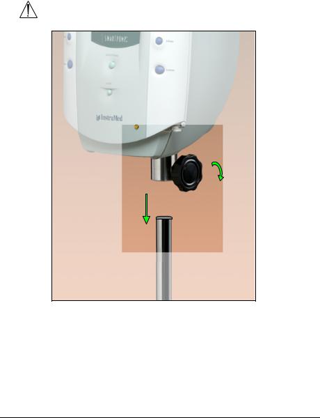
Mounting the SmartPump
WARNING: Ensure the SmartPump is mounted on the roll stand pole securely. Failure to comply may result in user/patient injury.
Cuff 2
Roll Stand Pole
1.Assemble roll stand. See instructions for use supplied with roll stand.
2.Gently lower the SmartPump onto the roll stand pole. Adjust the height of the SmartPump using the adjustment knob to facilitate access to the display and controls.
3.Tighten the knob to secure the SmartPump to the roll stand pole.
Preparing for Use |
17 |
 Loading...