


2020 Critical Care Bed

Renaissance Series
2020 Critical Care Bed
OPERATIONS MANUAL
For Parts or Technical Assistance
1–800–327–0770

Table of Contents
Introduction 2. . . . . . . . . . . . . . . . . . . . . . . . . . . . . . . . . . . . . . . . . . . . . . . . . . . . . . . . . . . . . . . . . . . . . . . . . . . . . . .
Specifications 2. . . . . . . . . . . . . . . . . . . . . . . . . . . . . . . . . . . . . . . . . . . . . . . . . . . . . . . . . . . . . . . . . . . . . . . . . . . . .
Warning / Caution / Note Definition 2. . . . . . . . . . . . . . . . . . . . . . . . . . . . . . . . . . . . . . . . . . . . . . . . . . . . . . . . . .
Set–up Procedures 3. . . . . . . . . . . . . . . . . . . . . . . . . . . . . . . . . . . . . . . . . . . . . . . . . . . . . . . . . . . . . . . . . . . . . . . .
Operation Guide
Operating Symbols 4. . . . . . . . . . . . . . . . . . . . . . . . . . . . . . . . . . . . . . . . . . . . . . . . . . . . . . . . . . . . . . . . . . . . . . .
Led Display 5. . . . . . . . . . . . . . . . . . . . . . . . . . . . . . . . . . . . . . . . . . . . . . . . . . . . . . . . . . . . . . . . . . . . . . . . . . . . . .
Function Lockout/Scale System On/Off/Reset 5. . . . . . . . . . . . . . . . . . . . . . . . . . . . . . . . . . . . . . . . . . . . . . . .
Cardiac Chair 5. . . . . . . . . . . . . . . . . . . . . . . . . . . . . . . . . . . . . . . . . . . . . . . . . . . . . . . . . . . . . . . . . . . . . . . . . . . .
Emergency Drop 5. . . . . . . . . . . . . . . . . . . . . . . . . . . . . . . . . . . . . . . . . . . . . . . . . . . . . . . . . . . . . . . . . . . . . . . . .
Emergency Stop 5. . . . . . . . . . . . . . . . . . . . . . . . . . . . . . . . . . . . . . . . . . . . . . . . . . . . . . . . . . . . . . . . . . . . . . . . .
Operating Directional Steering Caster 6. . . . . . . . . . . . . . . . . . . . . . . . . . . . . . . . . . . . . . . . . . . . . . . . . . . . . . .
Operating Optional Oxygen Bottle Holder 6. . . . . . . . . . . . . . . . . . . . . . . . . . . . . . . . . . . . . . . . . . . . . . . . . . . .
Using the 110 Volt Outlet Option 6. . . . . . . . . . . . . . . . . . . . . . . . . . . . . . . . . . . . . . . . . . . . . . . . . . . . . . . . . . . .
Operating Optional Permanently Attached I.V. Pole 7. . . . . . . . . . . . . . . . . . . . . . . . . . . . . . . . . . . . . . . . . . .
Using the Equipment Tray Options 7. . . . . . . . . . . . . . . . . . . . . . . . . . . . . . . . . . . . . . . . . . . . . . . . . . . . . . . . . .
Using the Optional X–Ray Cassette Holder 8. . . . . . . . . . . . . . . . . . . . . . . . . . . . . . . . . . . . . . . . . . . . . . . . . .
Control Panel Guide 9. . . . . . . . . . . . . . . . . . . . . . . . . . . . . . . . . . . . . . . . . . . . . . . . . . . . . . . . . . . . . . . . . . . . . . .
Weigh System Usage 10,11. . . . . . . . . . . . . . . . . . . . . . . . . . . . . . . . . . . . . . . . . . . . . . . . . . . . . . . . . . . . . . . . . . .
Weigh System Control Panel Guide 12,13. . . . . . . . . . . . . . . . . . . . . . . . . . . . . . . . . . . . . . . . . . . . . . . . . . . . . . .
Patient Control/Nurse Control Guide 14. . . . . . . . . . . . . . . . . . . . . . . . . . . . . . . . . . . . . . . . . . . . . . . . . . . . . . . .
Integrated Dynamic Mattress System Operation 15. . . . . . . . . . . . . . . . . . . . . . . . . . . . . . . . . . . . . . . . . . . . . .
Limited Warranty
Obtaining Parts and Service 16. . . . . . . . . . . . . . . . . . . . . . . . . . . . . . . . . . . . . . . . . . . . . . . . . . . . . . . . . . . . . .
Supplemental Warranty Coverage 16. . . . . . . . . . . . . . . . . . . . . . . . . . . . . . . . . . . . . . . . . . . . . . . . . . . . . . . . .
Return Authorization 17. . . . . . . . . . . . . . . . . . . . . . . . . . . . . . . . . . . . . . . . . . . . . . . . . . . . . . . . . . . . . . . . . . . . .
Freight Damage Claims 17. . . . . . . . . . . . . . . . . . . . . . . . . . . . . . . . . . . . . . . . . . . . . . . . . . . . . . . . . . . . . . . . . .

Introduction
INTRODUCTION
This manual is designed to assist you with the operation of the 2020 Renaissance Series Critical Care Bed.
Read it thoroughly before using the equipment.
SPECIFICATIONS
Maximum Weight Capacity 500 pounds
Overall Bed Length/Width 90”/38”
Minimum/Maximum Bed Height 22.5”/35”
Knee Gatch Angle 0 degrees to 35 degrees
Fowler Angle 0 to 90 Degrees
Trendelenberg/Reverse Trendelenberg –12 degrees to +12 degrees
Weigh System Accuracy (optional equipment) + / – 1% of total patient weight
Electrical Requirements 110 VAC, 60 Hz, 5.0 Amp
WARNING / CAUTION / NOTE DEFINITION
The words WARNING, CAUTION and NOTE carry special meanings and should be carefully reviewed.
WARNING
The personal safety of the patient or user may be involved. Disregarding this information could result in injury
to the patient or user.
CAUTION
These instructions point out special procedures or precautions that must be followed to avoid damaging the
equipment.
NOTE
This provides special information to make maintenance easier or important instructions clearer.
2

Set–Up Procedures
SET–UP PROCEDURES
It is important that the 2020 Renaissance Series Critical Care Bed is working properly before it is put into
service. The following list will help assure that each part of the bed is tested.
S Depress the curved pedal at either end of the bed fully to set the four wheel brakes and assure all
four casters lock. Lift the pedal to the neutral position to release the brakes.
S Lift the pedal and assure the steering caster locks at the foot end of the bed (on the patient’s right
side only). Depress the pedal fully to set the brakes.
S Assure the bed will lower to the full down position by depressing both pedals at the foot end of the
bed.
S Raise the bed to the full up position by pumping the pedal identified by the ”bed up” label on the base
hood. Assure the head end lowers to the full down position by depressing the pedal identified by the
Trendelenberg (head down) label.
S Depress the pedal identified by the Reverse Trendelenberg (foot down) label and assure the foot end
lowers to the full down position.
S Raise the bed to the full up position. Pivot the manual override Fowler crank up into position. Push
in the crank and hold it in while turning it clockwise to raise the Fowler. Assure it will raise to at least
90 degrees. Hold the crank in and turn it counterclockwise to lower the Fowler. Assure it will lower to
flat.
S Pivot the manual override Knee Gatch crank up into position. Push in the crank and hold it in while
turning it clockwise to raise the Knee Gatch. Assure it will raise to 35 degrees. Hold the crank in and
turn it counterclockwise to lower the Knee Gatch. Assure it will lower to flat.
S Assure the siderails raise and lower smoothly and lock in the up and intermediate positions.
S Plug the bed into a properly grounded, hospital grade wall receptacle. Assure the ”BED ON” light on
the foot end keypad comes on.
WARNING
The 2020 is equipped with a hospital grade plug for protection against shock hazard. It must be plugged directly into a properly grounded three–prong receptacle. Grounding reliability can be achieved only when a
hospital grade receptacle is used.
S Push the scale system On/Off/Reset switch (under the foot end frame end, next to the function lock-
out switches) away from you to turn on the weigh system (see page 5 for diagram).
S Run through each function on the head end and foot end control panels and assure that each is work-
ing properly (see control panel guide page 9 and weigh system control panel guide page 12 & 13).
S Assure all functions are working properly on the patient controls or the in–rail nurse controls, if the
bed is equipped with them.
3

Operation Guide
OPERATING SYMBOLS
Fowler Crank
T o raise the Fowler, push in the crank and hold it in while turning it clockwise.
To lower the Fowler, push in the crank and hold it in while turning it counter–
clockwise.
Knee Gatch Crank
To raise the Knee Gatch, push in the crank and hold it in while turning it
clockwise.
To lower the Knee Gatch, push in the crank and hold it in while turning it
counterclockwise.
Lift Pedal
Pump pedal to raise bed.
Trendelenberg Pedal
Depress pedal to lower head end.
Note: Depress both Trendelenberg pedals at the same time to lower litter.
Reverse Trendelenberg Pedal
Depress pedal to lower foot end.
Note: Depress both Trendelenberg pedals at the same time to lower litter.
Brake/Steer Pedal
Depress pedal fully to set four wheel brakes.
Lift pedal fully to engage steer caster.
4
Operation Guide
LED DISPLAY
There is an optional LED display to show the angle of the Fowler and the angle of Trendelenberg/Reverse
Trendelenberg. The Fowler display lights will change as the Fowler is moved electrically by pressing the control panel button or manually by cranking. The bed must be plugged into a wall socket for the display lights
to work. The Fowler display is for 15 degree increments only . The Trendelenberg display lights will change
whenever the angle of T rendelenberg/Reverse Trendelenberg is changed electrically by pressing the control
panel button or manually by depressing the pedals. Again, the bed must be plugged in for the lights to work.
The Trendelenberg display is for 4 degree increments only.
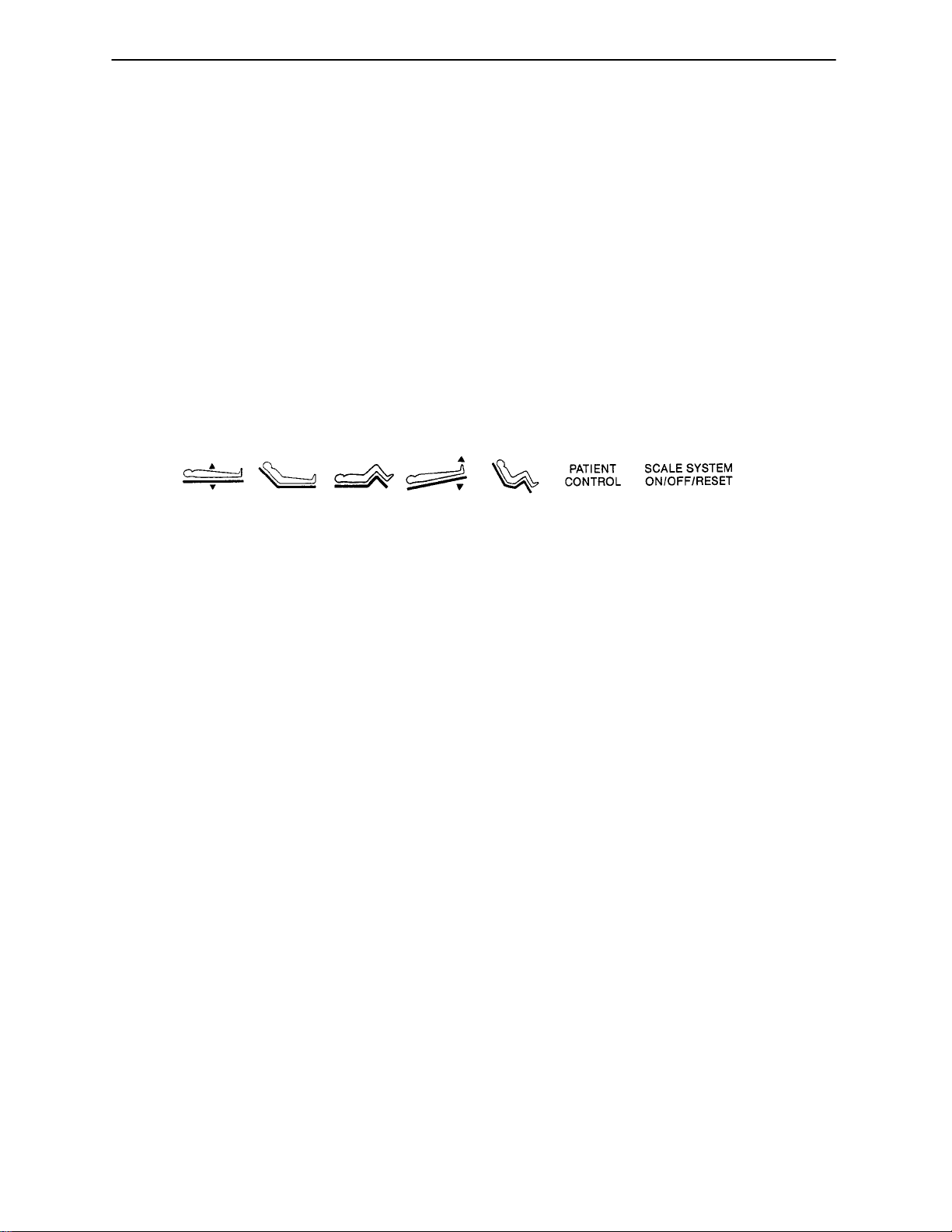
FUNCTION LOCKOUT/SCALE SYSTEM ON/OFF/RESET
Under the foot end keypad, there are seven lockout switches. These switches are identified with symbols
(see below). Pull the switch toward you to individually lock out bed up/down, Fowler, Knee Gatch, Trendelenberg/Reverse Trendelenberg, cardiac chair (optional) and the patient controls (optional). If the keypad button
is pressed for a function that is locked out, a horn will sound and the bed will not respond. The seventh switch
at the far right of the group is the scale system on/off/reset switch. It is used to reset the scale system if an
unusual symbol or character is displayed on the scale monitor or if the scale system operates in any other
erratic manner. It will not clear the bed zero information stored in the scale system memory.
CARDIAC CHAIR
To activate the optional Cardiac Chair function, press and hold the button on the foot end control panel. The
Knee Gatch will raise, the Fowler will raise or lower to 51 degrees and the bed will tilt to –12 degrees Reverse
Trendelenberg. Release the button to stop bed movement: hold the button until movement stops to complete
the function.
EMERGENCY DROP
To activate the optional Emergency Drop function, press and hold the ”ON” button on the foot end control
panel for two seconds. The bed will level from Trendelenberg/Reverse Trendelenberg, the Fowler will lower
to flat, the Knee Gatch will lower to flat and the litter will lower to full down. Press the ”OFF” button when the
function is complete.
NOTE
Both the Cardiac Chair and the Emergency Drop functions are stopped by safety switches if there is an obstruction under the Fowler or Knee Gatch. To start Cardiac Chair after clearing the obstruction, press the
function button again. To start Emergency Drop after clearing the obstruction, press the start button again.
EMERGENCY STOP
Pressing the Emergency Stop button on the head end control panel will interrupt any downward motion.
Emergency Stop overrides both control panels and the patient or in–rail nurse controls.
5
 Loading...