


Secure 2 3002
Med/Surg Bed
Model 3002
Maintenance Manual
For Parts or Technical Assistance
800–327–0770

Table of Contents
Introduction
Specifications 5. . . . . . . . . . . . . . . . . . . . . . . . . . . . . . . . . . . . . . . . . . . . . . . . . . . . . . . . . . . . . . . . . . . . . . . . . .
Warning / Caution / Note Definition 5. . . . . . . . . . . . . . . . . . . . . . . . . . . . . . . . . . . . . . . . . . . . . . . . . . . . . . . .
Safety Tips And Guidelines 6, 7. . . . . . . . . . . . . . . . . . . . . . . . . . . . . . . . . . . . . . . . . . . . . . . . . . . . . . . . . . . . . . . .
Limited Warranty
Obtaining Parts and Service 8. . . . . . . . . . . . . . . . . . . . . . . . . . . . . . . . . . . . . . . . . . . . . . . . . . . . . . . . . . . . . .
Extended Warranty Coverage 8. . . . . . . . . . . . . . . . . . . . . . . . . . . . . . . . . . . . . . . . . . . . . . . . . . . . . . . . . . . .
Return Authorization 9. . . . . . . . . . . . . . . . . . . . . . . . . . . . . . . . . . . . . . . . . . . . . . . . . . . . . . . . . . . . . . . . . . . .
Freight Damage Claims 9. . . . . . . . . . . . . . . . . . . . . . . . . . . . . . . . . . . . . . . . . . . . . . . . . . . . . . . . . . . . . . . . . .
Set–Up Procedures 10, 11. . . . . . . . . . . . . . . . . . . . . . . . . . . . . . . . . . . . . . . . . . . . . . . . . . . . . . . . . . . . . . . . . . . . .
Bed Symbols 12. . . . . . . . . . . . . . . . . . . . . . . . . . . . . . . . . . . . . . . . . . . . . . . . . . . . . . . . . . . . . . . . . . . . . . . . . . . . .
Bed Illustration 13. . . . . . . . . . . . . . . . . . . . . . . . . . . . . . . . . . . . . . . . . . . . . . . . . . . . . . . . . . . . . . . . . . . . . . . . . . . .
Bed Operation
Brake Pedal Operation 14. . . . . . . . . . . . . . . . . . . . . . . . . . . . . . . . . . . . . . . . . . . . . . . . . . . . . . . . . . . . . . . . .
Steer Pedal Operation 14. . . . . . . . . . . . . . . . . . . . . . . . . . . . . . . . . . . . . . . . . . . . . . . . . . . . . . . . . . . . . . . . . .
CPR Emergency Release Usage 15. . . . . . . . . . . . . . . . . . . . . . . . . . . . . . . . . . . . . . . . . . . . . . . . . . . . . . . . .
Foley Bag Hooks 15. . . . . . . . . . . . . . . . . . . . . . . . . . . . . . . . . . . . . . . . . . . . . . . . . . . . . . . . . . . . . . . . . . . . . .
Foot Prop Usage 15. . . . . . . . . . . . . . . . . . . . . . . . . . . . . . . . . . . . . . . . . . . . . . . . . . . . . . . . . . . . . . . . . . . . . .
Fracture Frame Usage 15. . . . . . . . . . . . . . . . . . . . . . . . . . . . . . . . . . . . . . . . . . . . . . . . . . . . . . . . . . . . . . . . .
Patient Restraint Strap Locations 15. . . . . . . . . . . . . . . . . . . . . . . . . . . . . . . . . . . . . . . . . . . . . . . . . . . . . . . .
Night Light Usage 16. . . . . . . . . . . . . . . . . . . . . . . . . . . . . . . . . . . . . . . . . . . . . . . . . . . . . . . . . . . . . . . . . . . . . .
Nurse Call Back–Up Battery 16. . . . . . . . . . . . . . . . . . . . . . . . . . . . . . . . . . . . . . . . . . . . . . . . . . . . . . . . . . . . .
CPR Board Usage 16. . . . . . . . . . . . . . . . . . . . . . . . . . . . . . . . . . . . . . . . . . . . . . . . . . . . . . . . . . . . . . . . . . . . .
I.V. Poles 17. . . . . . . . . . . . . . . . . . . . . . . . . . . . . . . . . . . . . . . . . . . . . . . . . . . . . . . . . . . . . . . . . . . . . . . . . . . . .
Positioning Siderails 18. . . . . . . . . . . . . . . . . . . . . . . . . . . . . . . . . . . . . . . . . . . . . . . . . . . . . . . . . . . . . . . . . . . .
Control Panel Lights 18. . . . . . . . . . . . . . . . . . . . . . . . . . . . . . . . . . . . . . . . . . . . . . . . . . . . . . . . . . . . . . . . . . . .
Siderail Function Guide 19, 20. . . . . . . . . . . . . . . . . . . . . . . . . . . . . . . . . . . . . . . . . . . . . . . . . . . . . . . . . . . . . .
Foot Board Control Panel Guide 21–24. . . . . . . . . . . . . . . . . . . . . . . . . . . . . . . . . . . . . . . . . . . . . . . . . . . . . .
Weigh System Control Panel Guide 25, 26. . . . . . . . . . . . . . . . . . . . . . . . . . . . . . . . . . . . . . . . . . . . . . . . . . .
Weigh System Usage 27, 28. . . . . . . . . . . . . . . . . . . . . . . . . . . . . . . . . . . . . . . . . . . . . . . . . . . . . . . . . . . . . . .
Pendant Controller 29. . . . . . . . . . . . . . . . . . . . . . . . . . . . . . . . . . . . . . . . . . . . . . . . . . . . . . . . . . . . . . . . . . . . .
Zoom Option Drive Wheel Operation 30, 31. . . . . . . . . . . . . . . . . . . . . . . . . . . . . . . . . . . . . . . . . . . . . . . . . .
Zoom Option Head End Control Panel Operation 32. . . . . . . . . . . . . . . . . . . . . . . . . . . . . . . . . . . . . . . . . . .
Zoom Option Battery Charging and Operation 33. . . . . . . . . . . . . . . . . . . . . . . . . . . . . . . . . . . . . . . . . . . . .
Cleaning and Preventative Maintenance 34, 35. . . . . . . . . . . . . . . . . . . . . . . . . . . . . . . . . . . . . . . . . . . . . . . . . . .
Static Discharge Precautions 36. . . . . . . . . . . . . . . . . . . . . . . . . . . . . . . . . . . . . . . . . . . . . . . . . . . . . . . . . . . . . . .
Troubleshooting 37, 38. . . . . . . . . . . . . . . . . . . . . . . . . . . . . . . . . . . . . . . . . . . . . . . . . . . . . . . . . . . . . . . . . . . . . . . .
Bed Circuit Boards 39–47. . . . . . . . . . . . . . . . . . . . . . . . . . . . . . . . . . . . . . . . . . . . . . . . . . . . . . . . . . . . . . . . . . . . .
Bed Communications Tester 48. . . . . . . . . . . . . . . . . . . . . . . . . . . . . . . . . . . . . . . . . . . . . . . . . . . . . . . . . . . . . . . .
Headwall Output Configuration 49. . . . . . . . . . . . . . . . . . . . . . . . . . . . . . . . . . . . . . . . . . . . . . . . . . . . . . . . . . . . . .

Table of Contents
Replacement Parts Quick Reference 50, 51. . . . . . . . . . . . . . . . . . . . . . . . . . . . . . . . . . . . . . . . . . . . . . . . . . . . . .
Base Maintenance Procedures
Brake Pedal Replacement 52. . . . . . . . . . . . . . . . . . . . . . . . . . . . . . . . . . . . . . . . . . . . . . . . . . . . . . . . . . . . . .
Lift Motor and Capacitor Removal and Replacement 53. . . . . . . . . . . . . . . . . . . . . . . . . . . . . . . . . . . . . . . .
Lift Motor Isolation Plate Replacement 54. . . . . . . . . . . . . . . . . . . . . . . . . . . . . . . . . . . . . . . . . . . . . . . . . . . .
Lift Housing Removal and Replacement 55, 56. . . . . . . . . . . . . . . . . . . . . . . . . . . . . . . . . . . . . . . . . . . . . . .
Lift Potentiometer Replacement and Adjustment 57, 58. . . . . . . . . . . . . . . . . . . . . . . . . . . . . . . . . . . . . . . .
Lift Potentiometer “Burn–In” Procedure 58. . . . . . . . . . . . . . . . . . . . . . . . . . . . . . . . . . . . . . . . . . . . . . . . . . .
Lift Motor Coupler Replacement 59. . . . . . . . . . . . . . . . . . . . . . . . . . . . . . . . . . . . . . . . . . . . . . . . . . . . . . . . .
Power and Sensor Coil Cord Replacement 60, 61. . . . . . . . . . . . . . . . . . . . . . . . . . . . . . . . . . . . . . . . . . . . .
Zoom Option Battery Removal and Replacement 62. . . . . . . . . . . . . . . . . . . . . . . . . . . . . . . . . . . . . . . . . . .
Zoom Option Power Board Removal and Replacement 63. . . . . . . . . . . . . . . . . . . . . . . . . . . . . . . . . . . . .
Litter Maintenance Procedures
Knee Motor Removal and Replacement 64. . . . . . . . . . . . . . . . . . . . . . . . . . . . . . . . . . . . . . . . . . . . . . . . . . .
Head Motor Cam and Cam Guide Replacement 65. . . . . . . . . . . . . . . . . . . . . . . . . . . . . . . . . . . . . . . . . . . .
Head Motor Limit Setting 66. . . . . . . . . . . . . . . . . . . . . . . . . . . . . . . . . . . . . . . . . . . . . . . . . . . . . . . . . . . . . . . .
Head Motor Removal and Replacement 67. . . . . . . . . . . . . . . . . . . . . . . . . . . . . . . . . . . . . . . . . . . . . . . . . . .
Head Motor Drive Isolator and CPR Decoupler Removal and Replacement 68. . . . . . . . . . . . . . . . . . . .
Head Motor Drive Screw and Ball Nut Replacement 69, 70. . . . . . . . . . . . . . . . . . . . . . . . . . . . . . . . . . . . .
Head Motor Brake/Clutch Replacement 70. . . . . . . . . . . . . . . . . . . . . . . . . . . . . . . . . . . . . . . . . . . . . . . . . . .
Scale System Diagnostics 71. . . . . . . . . . . . . . . . . . . . . . . . . . . . . . . . . . . . . . . . . . . . . . . . . . . . . . . . . . . . . .
Scale System Calibration 72. . . . . . . . . . . . . . . . . . . . . . . . . . . . . . . . . . . . . . . . . . . . . . . . . . . . . . . . . . . . . . .
Load Cell Replacement 73, 74. . . . . . . . . . . . . . . . . . . . . . . . . . . . . . . . . . . . . . . . . . . . . . . . . . . . . . . . . . . . . .
Power Supply Replacement 74. . . . . . . . . . . . . . . . . . . . . . . . . . . . . . . . . . . . . . . . . . . . . . . . . . . . . . . . . . . . .
CPU Board Replacement 75. . . . . . . . . . . . . . . . . . . . . . . . . . . . . . . . . . . . . . . . . . . . . . . . . . . . . . . . . . . . . . .
Potentiometer “Burn–In” Procedure 75. . . . . . . . . . . . . . . . . . . . . . . . . . . . . . . . . . . . . . . . . . . . . . . . . . . . . .
Smart TV Interface “Burn–In” Procedure 76. . . . . . . . . . . . . . . . . . . . . . . . . . . . . . . . . . . . . . . . . . . . . . . . . .
Zoom Option Control Bar Potentiometer Replacement 77. . . . . . . . . . . . . . . . . . . . . . . . . . . . . . . . . . . . . .
Zoom Option Control Bar Potentiometer “Burn–In” Procedure 78. . . . . . . . . . . . . . . . . . . . . . . . . . . . . . . .
Zoom Option AC Crossover Board Replacement 79. . . . . . . . . . . . . . . . . . . . . . . . . . . . . . . . . . . . . . . . . . .
Zoom Option Display/CPU Board Replacement 79. . . . . . . . . . . . . . . . . . . . . . . . . . . . . . . . . . . . . . . . . . . .
Siderail Cover Removal 80. . . . . . . . . . . . . . . . . . . . . . . . . . . . . . . . . . . . . . . . . . . . . . . . . . . . . . . . . . . . . . . . .
Molded Siderail Replacement 81. . . . . . . . . . . . . . . . . . . . . . . . . . . . . . . . . . . . . . . . . . . . . . . . . . . . . . . . . . . .
Head End Siderail Cable Replacement 82, 83. . . . . . . . . . . . . . . . . . . . . . . . . . . . . . . . . . . . . . . . . . . . . . . . .
Siderail Assembly Removal 84. . . . . . . . . . . . . . . . . . . . . . . . . . . . . . . . . . . . . . . . . . . . . . . . . . . . . . . . . . . . .
Foot Board Hinge Removal 85. . . . . . . . . . . . . . . . . . . . . . . . . . . . . . . . . . . . . . . . . . . . . . . . . . . . . . . . . . . . .
Foot Board Module Replacement 85. . . . . . . . . . . . . . . . . . . . . . . . . . . . . . . . . . . . . . . . . . . . . . . . . . . . . . . .
Foot Board Interface Plug Replacement 86. . . . . . . . . . . . . . . . . . . . . . . . . . . . . . . . . . . . . . . . . . . . . . . . . .

Table of Contents
Assembly Drawings and Parts Lists
Bed Assembly 88, 89. . . . . . . . . . . . . . . . . . . . . . . . . . . . . . . . . . . . . . . . . . . . . . . . . . . . . . . . . . . . . . . . . . . . . .
Base Assembly and Options 90–98. . . . . . . . . . . . . . . . . . . . . . . . . . . . . . . . . . . . . . . . . . . . . . . . . . . . . . . . .
Lift Assembly 99–102. . . . . . . . . . . . . . . . . . . . . . . . . . . . . . . . . . . . . . . . . . . . . . . . . . . . . . . . . . . . . . . . . . . . . .
Motor Isolation Plate Assembly 103. . . . . . . . . . . . . . . . . . . . . . . . . . . . . . . . . . . . . . . . . . . . . . . . . . . . . . . . .
Brake Shaft Assembly 104. . . . . . . . . . . . . . . . . . . . . . . . . . . . . . . . . . . . . . . . . . . . . . . . . . . . . . . . . . . . . . . . .
Brake Crank Assembly 105. . . . . . . . . . . . . . . . . . . . . . . . . . . . . . . . . . . . . . . . . . . . . . . . . . . . . . . . . . . . . . . .
Brake Bar Assembly 106. . . . . . . . . . . . . . . . . . . . . . . . . . . . . . . . . . . . . . . . . . . . . . . . . . . . . . . . . . . . . . . . . .
Caster Assembly 107–112. . . . . . . . . . . . . . . . . . . . . . . . . . . . . . . . . . . . . . . . . . . . . . . . . . . . . . . . . . . . . . . . .
Zoom Option Base Assembly 113–120. . . . . . . . . . . . . . . . . . . . . . . . . . . . . . . . . . . . . . . . . . . . . . . . . . . . . . .
Zoom Option Drive Wheel Lift Lever Assembly 121. . . . . . . . . . . . . . . . . . . . . . . . . . . . . . . . . . . . . . . . . . . .
Zoom Option Bottom Covers 122. . . . . . . . . . . . . . . . . . . . . . . . . . . . . . . . . . . . . . . . . . . . . . . . . . . . . . . . . . .
Zoom Option Drive Train Assembly 123. . . . . . . . . . . . . . . . . . . . . . . . . . . . . . . . . . . . . . . . . . . . . . . . . . . . . .
Zoom Option Battery Tray Assembly 124. . . . . . . . . . . . . . . . . . . . . . . . . . . . . . . . . . . . . . . . . . . . . . . . . . . .
Zoom Option Base Power Assembly 125. . . . . . . . . . . . . . . . . . . . . . . . . . . . . . . . . . . . . . . . . . . . . . . . . . . .
Litter Assembly and Options 126–132. . . . . . . . . . . . . . . . . . . . . . . . . . . . . . . . . . . . . . . . . . . . . . . . . . . . . . . .
Litter Covers 133, 134. . . . . . . . . . . . . . . . . . . . . . . . . . . . . . . . . . . . . . . . . . . . . . . . . . . . . . . . . . . . . . . . . . . . .
Electrical Litter Assembly 135–140. . . . . . . . . . . . . . . . . . . . . . . . . . . . . . . . . . . . . . . . . . . . . . . . . . . . . . . . . .
Mechanical Litter Assembly 141–145. . . . . . . . . . . . . . . . . . . . . . . . . . . . . . . . . . . . . . . . . . . . . . . . . . . . . . . .
Lift Header Assembly 146, 147. . . . . . . . . . . . . . . . . . . . . . . . . . . . . . . . . . . . . . . . . . . . . . . . . . . . . . . . . . . . . .
230V Surge Suppressor Assembly 148. . . . . . . . . . . . . . . . . . . . . . . . . . . . . . . . . . . . . . . . . . . . . . . . . . . . . .
Gatch Motor Assembly 149. . . . . . . . . . . . . . . . . . . . . . . . . . . . . . . . . . . . . . . . . . . . . . . . . . . . . . . . . . . . . . . .
Fowler Drive Assembly 150–152. . . . . . . . . . . . . . . . . . . . . . . . . . . . . . . . . . . . . . . . . . . . . . . . . . . . . . . . . . . .
Fowler Limit Switch Assembly 154, 155. . . . . . . . . . . . . . . . . . . . . . . . . . . . . . . . . . . . . . . . . . . . . . . . . . . . . .
Night Light Assembly 156, 157. . . . . . . . . . . . . . . . . . . . . . . . . . . . . . . . . . . . . . . . . . . . . . . . . . . . . . . . . . . . . .
Scale/Bed Exit Option Assembly 158, 159. . . . . . . . . . . . . . . . . . . . . . . . . . . . . . . . . . . . . . . . . . . . . . . . . . . .
Zoom Option Litter Assembly 160–166. . . . . . . . . . . . . . . . . . . . . . . . . . . . . . . . . . . . . . . . . . . . . . . . . . . . . . .
Head End Siderail Assembly 167–186. . . . . . . . . . . . . . . . . . . . . . . . . . . . . . . . . . . . . . . . . . . . . . . . . . . . . . .
Siderail Panels 187, 188. . . . . . . . . . . . . . . . . . . . . . . . . . . . . . . . . . . . . . . . . . . . . . . . . . . . . . . . . . . . . . . . . . .
Head End Siderail Latch Assembly 189, 190. . . . . . . . . . . . . . . . . . . . . . . . . . . . . . . . . . . . . . . . . . . . . . . . . .
Optional Smart TV Siderail Modules 191, 192. . . . . . . . . . . . . . . . . . . . . . . . . . . . . . . . . . . . . . . . . . . . . . . . .
Foot End Siderail Assembly 193–195. . . . . . . . . . . . . . . . . . . . . . . . . . . . . . . . . . . . . . . . . . . . . . . . . . . . . . . .
Foot End Siderail Latch Assembly 196. . . . . . . . . . . . . . . . . . . . . . . . . . . . . . . . . . . . . . . . . . . . . . . . . . . . . . .
Siderail Release Lever Assembly 197, 198. . . . . . . . . . . . . . . . . . . . . . . . . . . . . . . . . . . . . . . . . . . . . . . . . . .
Siderail Bypass Detent Clip Assembly 199. . . . . . . . . . . . . . . . . . . . . . . . . . . . . . . . . . . . . . . . . . . . . . . . . . .
Pendants 200. . . . . . . . . . . . . . . . . . . . . . . . . . . . . . . . . . . . . . . . . . . . . . . . . . . . . . . . . . . . . . . . . . . . . . . . . . . .

Table of Contents
Assembly Drawings and Parts Lists (Continued)
Foot Board Assembly 201–209. . . . . . . . . . . . . . . . . . . . . . . . . . . . . . . . . . . . . . . . . . . . . . . . . . . . . . . . . . . . .
Foot Board Standard Module 210. . . . . . . . . . . . . . . . . . . . . . . . . . . . . . . . . . . . . . . . . . . . . . . . . . . . . . . . . . .
Foot Board Bed Exit Module 211, 212. . . . . . . . . . . . . . . . . . . . . . . . . . . . . . . . . . . . . . . . . . . . . . . . . . . . . . . .
Foot Board Scale Module 213. . . . . . . . . . . . . . . . . . . . . . . . . . . . . . . . . . . . . . . . . . . . . . . . . . . . . . . . . . . . . .
Head Board Assembly 214. . . . . . . . . . . . . . . . . . . . . . . . . . . . . . . . . . . . . . . . . . . . . . . . . . . . . . . . . . . . . . . . .
CPR Board Assembly 215. . . . . . . . . . . . . . . . . . . . . . . . . . . . . . . . . . . . . . . . . . . . . . . . . . . . . . . . . . . . . . . . .
Removable I.V. Assembly 216, 217. . . . . . . . . . . . . . . . . . . . . . . . . . . . . . . . . . . . . . . . . . . . . . . . . . . . . . . . . .
Permanent I.V. Assembly 218–220. . . . . . . . . . . . . . . . . . . . . . . . . . . . . . . . . . . . . . . . . . . . . . . . . . . . . . . . . .
Defibrillator Tray Assembly 221. . . . . . . . . . . . . . . . . . . . . . . . . . . . . . . . . . . . . . . . . . . . . . . . . . . . . . . . . . . . .
Pleur–Evac Rack with Defibrillator Tray 222, 223. . . . . . . . . . . . . . . . . . . . . . . . . . . . . . . . . . . . . . . . . . . . . .
Pleur–Evac Rack Assembly 224. . . . . . . . . . . . . . . . . . . . . . . . . . . . . . . . . . . . . . . . . . . . . . . . . . . . . . . . . . . .
Siderail Pleur–Evac Rack Assembly 225. . . . . . . . . . . . . . . . . . . . . . . . . . . . . . . . . . . . . . . . . . . . . . . . . . . . .
Pump Rack Assembly 226. . . . . . . . . . . . . . . . . . . . . . . . . . . . . . . . . . . . . . . . . . . . . . . . . . . . . . . . . . . . . . . . .
90 Power Cord Assembly 227. . . . . . . . . . . . . . . . . . . . . . . . . . . . . . . . . . . . . . . . . . . . . . . . . . . . . . . . . . . . .
Accessory Adapter Frame Assembly 228, 229. . . . . . . . . . . . . . . . . . . . . . . . . . . . . . . . . . . . . . . . . . . . . . . .
Litter Roller Assembly 230, 231. . . . . . . . . . . . . . . . . . . . . . . . . . . . . . . . . . . . . . . . . . . . . . . . . . . . . . . . . . . . .
Bed Extender Assembly 232, 233. . . . . . . . . . . . . . . . . . . . . . . . . . . . . . . . . . . . . . . . . . . . . . . . . . . . . . . . . . .
Bed Extender Mattress 234. . . . . . . . . . . . . . . . . . . . . . . . . . . . . . . . . . . . . . . . . . . . . . . . . . . . . . . . . . . . . . . .
Oxygen Bottle Holder Assembly 235. . . . . . . . . . . . . . . . . . . . . . . . . . . . . . . . . . . . . . . . . . . . . . . . . . . . . . . .
Traction Socket Extensions 236. . . . . . . . . . . . . . . . . . . . . . . . . . . . . . . . . . . . . . . . . . . . . . . . . . . . . . . . . . . .
Urine Bottle Hanger 237. . . . . . . . . . . . . . . . . . . . . . . . . . . . . . . . . . . . . . . . . . . . . . . . . . . . . . . . . . . . . . . . . . .
Telephone Mounting Bracket 238. . . . . . . . . . . . . . . . . . . . . . . . . . . . . . . . . . . . . . . . . . . . . . . . . . . . . . . . . . .
Padded Siderail Covers 239. . . . . . . . . . . . . . . . . . . . . . . . . . . . . . . . . . . . . . . . . . . . . . . . . . . . . . . . . . . . . . . .

Introduction
INTRODUCTION
This manual is designed to assist you with the maintenance of the Model 3002 Secure II Bed. Read it thoroughly before beginning any maintenance on the equipment.
SPECIFICATIONS
Maximum Weight Capacity 500 pounds (227 kilograms)
Overall Bed Length/Width 93” x 42–1/2” (siderails up) – 36” (siderails down)
238 cm. x 109 cm. (siderails up) – 92 cm. (siderails down)
Patient Sleep Surface 84” x 35” – 215 cm. x 90 cm.
Bed Height (to top of seat litter) 16” (Low) x 29–1/2” (High) – 41 cm. (Low) x 76 cm. (High)
Beds with Zoom Option –19.5” x 29–1/2” – 49.5 cm. x 76 cm.
Knee Gatch Angle 0 to 40
Fowler Angle 0 to 60
Trendelenburg/Reverse Trendelenburg –12 to +12, –10 to +10 (Beds with Zoom Option)
Weigh System Accuracy
(optional equipment)
Electrical Requirements – all electrical re-
quirements meet UL 2601 specifications.
1% of total patient weight while the litter is level
2% of total patient weight with the litter at any angle
115 VAC, 60 Hz, 7.0 Amp.
230 VAC, 50/60 Hz, 4.0 Amp.
Stryker reserves the right to change specifications without notice.
WARNING / CAUTION / NOTE DEFINITION
The words WARNING, CAUTION and NOTE carry special meanings and should be carefully reviewed.
WARNING
The personal safety of the patient or user may be involved. Disregarding this information could result in injury
to the patient or user.
CAUTION
These instructions point out special procedures or precautions that must be followed to avoid damaging the
equipment.
NOTE
This provides special information to make important instructions clearer.
WARNING
Always apply the caster brakes when a patient is getting on or off the bed. Push on the bed to ensure the
brakes are securely locked. Always engage the brakes unless the bed is being moved. Injury could result
if the bed moves while a patient is getting on or off the bed.
5

Introduction
SAFETY TIPS AND GUIDELINES
Before operating the Secure II Bed, it is important to read and understand all information in this manual. Carefully read and strictly follow the safety guidelines listed on this page.
It is important that all users have been trained and educated on the inherent hazards associated with the
usage of electric beds.
WARNING
The Secure II Bed is not intended for use with patients less than two years of age.
Serious injury can result if caution is not used when operating the unit. Operate the unit only when all
persons are clear of the electrical and mechanical systems.
To help reduce the number and severity of falls by patients, always leave the bed in the lowest position
when the patient is unattended.
Leave the siderails fully up and locked when the patient is unattended. When raising the siderails, listen
for the ”click” that indicates the siderail has locked in the up position. Pull firmly on the siderail to ensure
it is locked into position.
Siderails are not intended to be a patient restraint device. It is the responsibility of the attending medical
personnel to determine the degree of restraint necessary to ensure a patient will remain safely in bed.
Always apply the caster brakes when a patient is on the bed (except during transport). Serious injury
could result if the bed moves while a patient is getting in or out of bed. After the brake pedal is applied,
push on the bed to ensure the brakes are locked.
Ensure the brakes are completely released prior to attempting to move the unit. Attempting to move the
unit with the brakes actuated could result in injury to the user and/or patient.
Do not attempt to move the foot end of the bed laterally when the steer pedal is activated. When the steer
pedal is activated, the steer caster at the foot end of the bed cannot swivel. Attempting to move the bed
laterally when the steer pedal is activated may cause injury to the user.
When attaching equipment to the frame, ensure it will not impede normal frame operation. For example:
hooks on hanging equipment must not actuate control buttons, equipment must not hide the nurse call
button, etc.
The Chaperone Bed Exit System is intended only to aid in the detection of a patient exiting the unit.
It is NOT intended to replace patient monitoring protocol. The bed exit system signals when a patient
is about to exit. Adding or subtracting objects from the frame after zeroing the weigh system may cause
a reduction in the sensitivity of the bed exit system.
When large spills occur in the area of the circuit boards, 110 volt cables and motors, immediately unplug
the bed power cord from the wall socket. Remove the patient from the bed and clean up the fluid. Have
maintenance completely check the bed. Fluids can affect the operational capabilities of any electrical
product. DO NOT put the bed back into service until it is completely dry and has been thoroughly tested
for safe operation.
Do not steam clean or hose off the bed. Do not immerse any part of the bed. The internal electric parts
may be damaged by exposure to water. Hand wash all surfaces of the bed with warm water and mild
detergent. Dry thoroughly. Quaternary Germicidal Disinfectants, used as directed, and/or Chlorine
Bleach products, typically 5.25% Sodium Hypochlorite in dilutions ranging between 1 part bleach to 100
parts water, and 2 parts bleach to 100 parts water are not considered mild detergents. THESE PROD-
UCTS ARE CORROSIVE IN NA TURE AND MAY CAUSE DAMAGE TO YOUR BED IF USED IMPROPERLY. If these types of products are used to clean Stryker patient care equipment, measures must be
taken to insure the beds are wiped with clean water and thoroughly dried following cleaning. Failure to
properly rinse and dry the beds will leave a corrosive residue on the surface of the bed, possibly causing
premature corrosion of critical components. Failure to follow the above directions when using these types
of cleaners may void this product’s warranty.
Clean Velcro AFTER EACH USE. Saturate Velcro with disinfectant and allow disinfectant to evaporate.
(Appropriate disinfectant for nylon Velcro should be determined by the hospital.)
6

Introduction
SAFETY TIPS AND GUIDELINES (CONTINUED)
WARNING
Preventative maintenance should be performed at a minimum of biannually to ensure all bed features
are functioning properly. Close attention should be given to safety features including, but not limited to:
safety side latching mechanisms, frayed electrical cords and components, all electrical controls return
to off or neutral position when released, caster braking systems, no controls or cabling entangled in bed
mechanisms, leakage current 100 microamps maximum, scale and bed exit systems calibrated properly .
Always unplug the bed power cord from the wall socket and push the battery power on/off switch to the
“OFF” position before servicing or cleaning the bed. When working under the bed with the bed in the high
position, always place blocks under the litter frame and apply the brakes to prevent injury in case the Bed
Down switch is accidently pressed.
SAFETY TIPS AND GUIDELINES (ZOOM OPTION)
WARNING
USE CAUTION while maneuvering the unit with the drive wheel activated. Always ensure there are no
obstacles near the unit while the drive wheel is activated. Injury to the patient, user or bystanders or damage to the frame or surrounding equipment could occur if the unit collides with an obstacle.
Serious injury can result if caution is not used when operating the unit. Operate the unit only when all
persons are clear of the electrical and mechanical systems.
Put the drive wheel in the neutral position and release the brakes before pushing the unit manually. Do
not attempt to push the unit manually with the drive wheel engaged. The unit will be difficult to push and
injury could result.
If unanticipated motion occurs, unplug the power cord from the wall socket, push the battery power on/off
switch to the ”OFF” position (the LED will not be illuminated) and actuate the drive wheel pedal to the
neutral position.
The power save mode is activated after one hour on battery power with no motion release switch activa-
tion. Functions including Bed Exit, scale and motion will cease to operate when the unit enters the power
save mode. Injury to the patient could occur if proper patient monitoring protocol is not observed.
Always unplug the power cord and push the battery power on/off switch to the “OFF” position before ser-
vice or cleaning. When working under the frame, always place blocks under the litter frame to prevent
injury in case the Bed Down switch is accidently activated.
The battery tray assembly weighs 50 pounds. T ake care when removing the two hex head screws secur-
ing it to the base frame or personal injury could result.
Battery posts, terminals and related accessories contain lead and lead compounds, chemicals known
to the State of California to cause cancer and birth defects or other reproductive harm. Wash hands after
handling.
7

Warranty
Limited Warranty:
Stryker Medical Division, a division of Stryker Corporation, warrants to the original purchaser that its products
should be free from defects in material and workmanship for a period of one (1) year after date of delivery.
Stryker’s obligation under this warranty is expressly limited to supplying replacement parts and labor for, or
replacing, at its option, any product which is, in the sole discretion of Stryker, found to be defective. Stryker
warrants to the original purchaser that the frame and welds on its beds will be free from structural defects
for as long as the original purchaser owns the bed. If requested by Stryker, products or parts for which a
warranty claim is made shall be returned prepaid to Stryker’s factory. Any improper use or any alteration or
repair by others in such manner as in Stryker’s judgement affects the product materially and adversely shall
void this warranty. Any repair of Stryker products using parts not provided or authorized by Stryker shall void
this warranty. No employee or representative of Stryker is authorized to change this warranty in any way.
Stryker Medical stretchers are designed for a 10 year expected life under normal use conditions and appropriate periodic maintenance as described in the maintenance manual for each device.
This statement constitutes Stryker’s entire warranty with respect to the aforesaid equipment. STRYKER
MAKES NO OTHER WARRANTY OR REPRESENTATION, EITHER EXPRESSED OR IMPLIED, EXCEPT
AS SET FORTH HEREIN. THERE IS NO WARRANTY OF MERCHANTABILITY AND THERE ARE NO
WARRANTIES OF FITNESS FOR ANY PARTICULAR PURPOSE. IN NO EVENT SHALL STRYKER BE
LIABLE HEREUNDER FOR INCIDENTAL OR CONSEQUENTIAL DAMAGES ARISING FROM OR IN ANY
MANNER RELATED TO SALES OR USE OF ANY SUCH EQUIPMENT.
To Obtain Parts and Service:
Stryker products are supported by a nationwide network of dedicated Stryker Field Service Representatives.
These representatives are factory trained, available locally, and carry a substantial spare parts inventory to
minimize repair time. Simply call your local representative, or call Stryker Customer Service at (800)
327–0770.
Service Contract Coverage:
Stryker has developed a comprehensive program of service contract options designed to keep your equipment operating at peak performance at the same time it eliminates unexpected costs. We recommend that
these programs be activated before the expiration of the new product warranty to eliminate the potential of
additional equipment upgrade charges.
A SERVICE CONTRACT HELPS TO:
Ensure equipment reliability
Stabilize maintenance budgets
Diminish downtime
Establish documentation for JCAHO
Increase product life
Enhance trade–in value
Address risk management and safety
8

Warranty
Stryker offers the following service contract programs:
SPECIFICATIONS GOLD SILVER PM* ONLY
Annually scheduled preventative maintenance X X
All parts,** labor, and travel X X
Unlimited emergency service calls X X
Priority one contact; two hour phone response X X X
Most repairs will be completed within 3 business days X X
JCAHO documentation X X X
On–site log book w/ preventative maintenance & emergency service records X
Factory–trained Stryker Service Technicians X X X
Stryker authorized parts X X X
End of year summary X
Stryker will perform all service during regular business hours (9–5) X X X
* Replacement parts and labor for products under PM contract will be discounted.
** Does not include any disposable items, I.V. poles (except for Stryker HD permanent poles), mattresses, or damage re-
sulting from abuse.
Stryker Medical also offers personalized service contracts.
Pricing is determined by age, location, model and condition of product.
For more information on our service contracts,
please call your local representative or call (800) 327–0770 (option #2).
Return Authorization:
Merchandise cannot be returned without approval from the Stryker Customer Service Department. An authorization number will be provided which must be printed on the returned merchandise. Stryker reserves the
right to charge shipping and restocking fees on returned items.
SPECIAL, MODIFIED, OR DISCONTINUED ITEMS NOT SUBJECT TO RETURN.
Damaged Merchandise:
ICC Regulations require that claims for damaged merchandise must be made with the carrier within fifteen
(15) days of receipt of merchandise. DO NOT ACCEPT DAMAGED SHIPMENTS UNLESS SUCH DAMAGE
IS NOTED ON THE DELIVERY RECEIPT AT THE TIME OF RECEIPT. Upon prompt notification, Stryker
will file a freight claim with the appropriate carrier for damages incurred. Claim will be limited in amount to
the actual replacement cost. In the event that this information is not received by Stryker within the fifteen
(15) day period following the delivery of the merchandise, or the damage was not noted on the delivery receipt
at the time of receipt, the customer will be responsible for payment of the original invoice in full.
Claims for any short shipment must be made within thirty (30) days of invoice.
International Warranty Clause:
This warranty reflects U.S. domestic policy. Warranty outside the U.S. may vary by country. Please contact
your local Stryker Medical representative for additional information.
9

Set–Up Procedures
SET–UP PROCEDURES
It is important that the Secure II Bed is working properly before it is put into service. The following list will
help ensure that each part of the bed is tested.
Plug the bed into a properly grounded, hospital grade wall receptacle and ensure the ”Power” LED light
at the foot end of the bed comes on.
WARNING
The Secure II is equipped with a hospital grade plug for protection against shock hazard. It must be plugged
directly into a properly grounded three–prong receptacle. Grounding reliability can be achieved only when
a hospital grade receptacle is used.
Plug the optional interface cable into the 37 pin connector under the litter frame at the head end of the
bed, and into the ”Patient Station”, ”Head Wall”, ”Docker Station”, or equivalent (whichever applies). Test
the interface cable to verify it is functioning properly.
WARNING
Use only a Stryker supplied interface cable. Use of any other cable may cause the bed to function improperly
which may result in patient or user injury.
Ensure the siderails raise, lower and store smoothly and lock in the up position and in the intermediate
position when lowered (page 18).
Ensure that all four casters lock when the brake pedal is engaged (page 14).
Raise the Back up to approximately 60. Squeeze the CPR release handle and ensure the Back and
Knee will drop with minimal effort.
NOTE
Ensure that the ”Brake Not Set” LEDs located on the outside of the head end siderails and on the foot board
control panel come on when the brakes are disengaged.
Run through each function on the foot board control panel to ensure that each function is working properly
(page 21–26).
Run through each function on both head end siderails to ensure that each is working properly (page
18–20).
Activate the motion stop system to ensure it is functioning properly: press and hold down the BED DOWN
key. As the bed lowers, lift up on the motion interrupt pan (reference drawing on page 13) and ensure
the downward motion stops. Release the pan and allow the downward motion to continue.
NOTE
The bed’s upward motion or other functions are not disrupted by the motion stop system.
10

Set–Up Procedures
SET–UP PROCEDURES (ZOOMt OPTION)
If your bed is equipped with the Zoom drive wheel option, run through the set–up procedures on page 10
and continue with the procedures listed below.
Plug the power cord into a properly grounded, hospital grade wall receptacle. The 12 volt batteries that
provide power to the drive wheel and back–up power to the unit functions will charge whenever the power
cord is plugged into the wall socket. The batteries require approximately 10 hours of charging time before
the bed is put into service.
Unplug the power cord from the wall socket. Push the battery power switch located on the lower left cor-
ner of the head end to the “ON” position. Again, verify each function on the foot board and siderails is
operating properly.
With the battery power switch in the “ON” position and the brakes engaged, ensure the “Release Brakes”
LED on the head end control panel is illuminated.
With the battery power switch in the “ON” position and the drive wheel in the neutral position (not touching
the floor), ensure the “Engage Drive Wheel” LED on the head end control panel is illuminated.
Run through the operation of the drive wheel (see page 30 & 31) to ensure it is operating properly.
If any problems are found during bed set–up, contact Stryker Customer Service at 800–327–0770.
Damaged Merchandise
ICC Regulations require that claims for damaged merchandise must be made with the carrier within fifteen
(15) days of receipt of merchandise. DO NOT ACCEPT DAMAGED SHIPMENTS UNLESS SUCH DAMAGE
IS NOTED ON THE DELIVERY RECEIPT AT THE TIME OF RECEIPT . Stryker Customer Service must be
notified immediately. Stryker will aid the customer in filing a freight claim with the appropriate carrier for damages incurred. Claim will be limited in amount to the actual replacement cost. In the event that this information
is not received by Stryker within the fifteen (15) day period following the delivery of the merchandise, or the
damage was not noted on the delivery receipt at the time of receipt, the customer will be responsible for payment of the original invoice in full.
Claims for any short shipment must be made within thirty (30) days of invoice.
11
Symbols
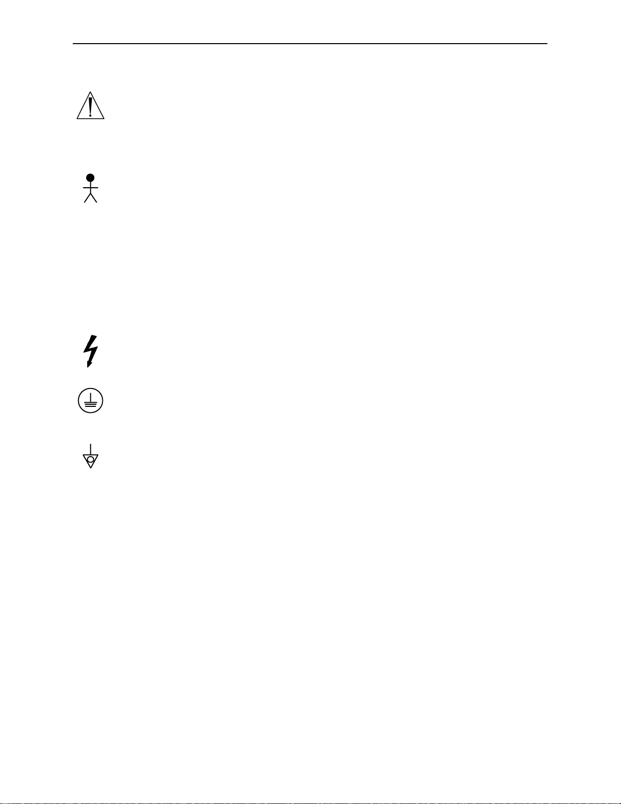
Warning, Refer to Service/Maintenance Manual
~
Alternating Current
Type B Equipment: equipment providing a particular degree of protection against electric shock, particularly regarding allowable leakage current and reliability of the protective earth connection.
Class 1 Equipment: equipment in which protection against electric shock does not rely
on BASIC INSULA TION only, but which includes an additional safety precaution in that
means are provided for the connection of the EQUIPMENT to the protective earth conductor in the fixed wiring of the installation in such a way that ACCESSIBLE METAL
PARTS cannot become live in the event of a failure of the BASIC INSULATION.
IPX4: Protection from liquid splash
Dangerous Voltage Symbol
Protective Earth Terminal
Potential Equalization Symbol
12
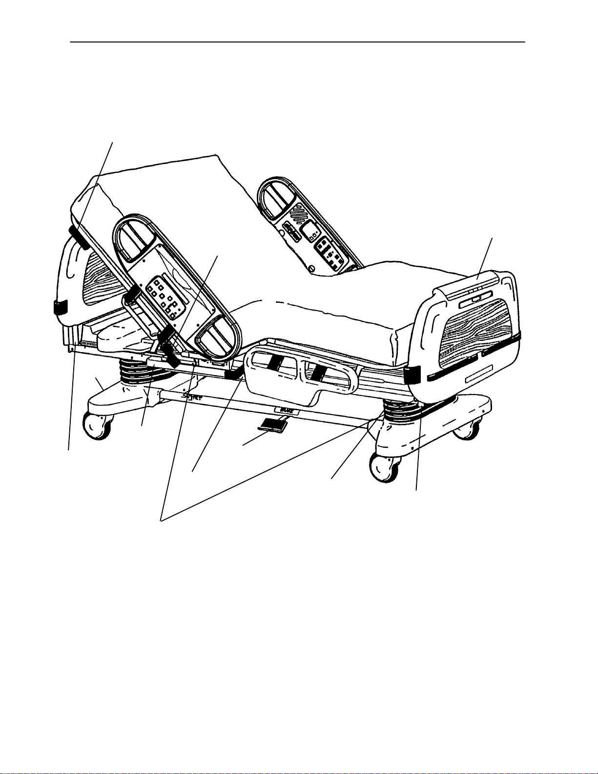
Bed Illustration
PATIENT’S
RIGHT
CPR Release
Handle
Steer
Pedal
HEAD END
Siderail Release
Handle
PATIENT’S
LEFT
Footboard
Control
Panel
FOOT END
I.V. and
Fracture Frame
Mount
Motion
Interrupt
Pan
Foley Bag Hooks
(Standard)
Night
Light
Brake Pedal
Foley Bag Hook
(Isolated)
(Optional Equip.)
I.V. and
Fracture Frame
Mount
13

Base Operation Guide
BRAKE PEDAL OPERATION
WARNING
Always apply the caster brakes when a patient is getting on or off the bed. Push on the bed to ensure the
brakes are securely locked. Always engage the brakes unless the bed is being moved. Injury could result
if the bed moves while a patient is getting on or off the bed.
To activate the brakes, push down once on one of the
pedals located at the midpoint of the bed on both sides
(identified by the label at right). The pedal will remain
in the lowered position, indicating the brakes are engaged. To disengage the brakes, push down once and
the pedal will return to the upper position.
NOTE
There are LED lights on the outside of the head end siderails and on the foot end control panel that will blink
when the brakes are not engaged only if the bed is plugged into a wall socket (see pages 20 & 22). The brakes
will still operate properly when the bed is not plugged in.
STEER PEDAL OPERATION (BEDS WITHOUT THE ZOOMt DRIVE WHEEL OPTION)
When the bed is moved, the steer caster helps guide the bed along a straight line and helps the bed pivot
around corners.
To activate the steer caster, move the pedal located
at the head end of the bed to your left as shown on
the label.
NOTE
For proper ”tracking” of the steer caster, push the bed approximately 10 feet to allow the wheels to face the
direction of travel before engaging the steer pedal. If this is not done, proper ”tracking” will not occur and the
bed will be difficult to steer.
WARNING
Do not attempt to move the foot end of the bed laterally when the steer pedal is activated. When the steer
pedal is activated, the steer caster at the foot end of the bed cannot swivel. Attempting to move the bed laterally when the steer pedal is activated may cause injury to the user.
14
Litter Operation Guide
CPR EMERGENCY RELEASE
When quick access to the patient is needed, and the Fowler is raised, squeeze one of the two red release
handles (see illustration, page 13) and the Fowler can be quickly guided down to a flat position.
NOTE
The handle can be released at any time to stop the Fowler from lowering.
A
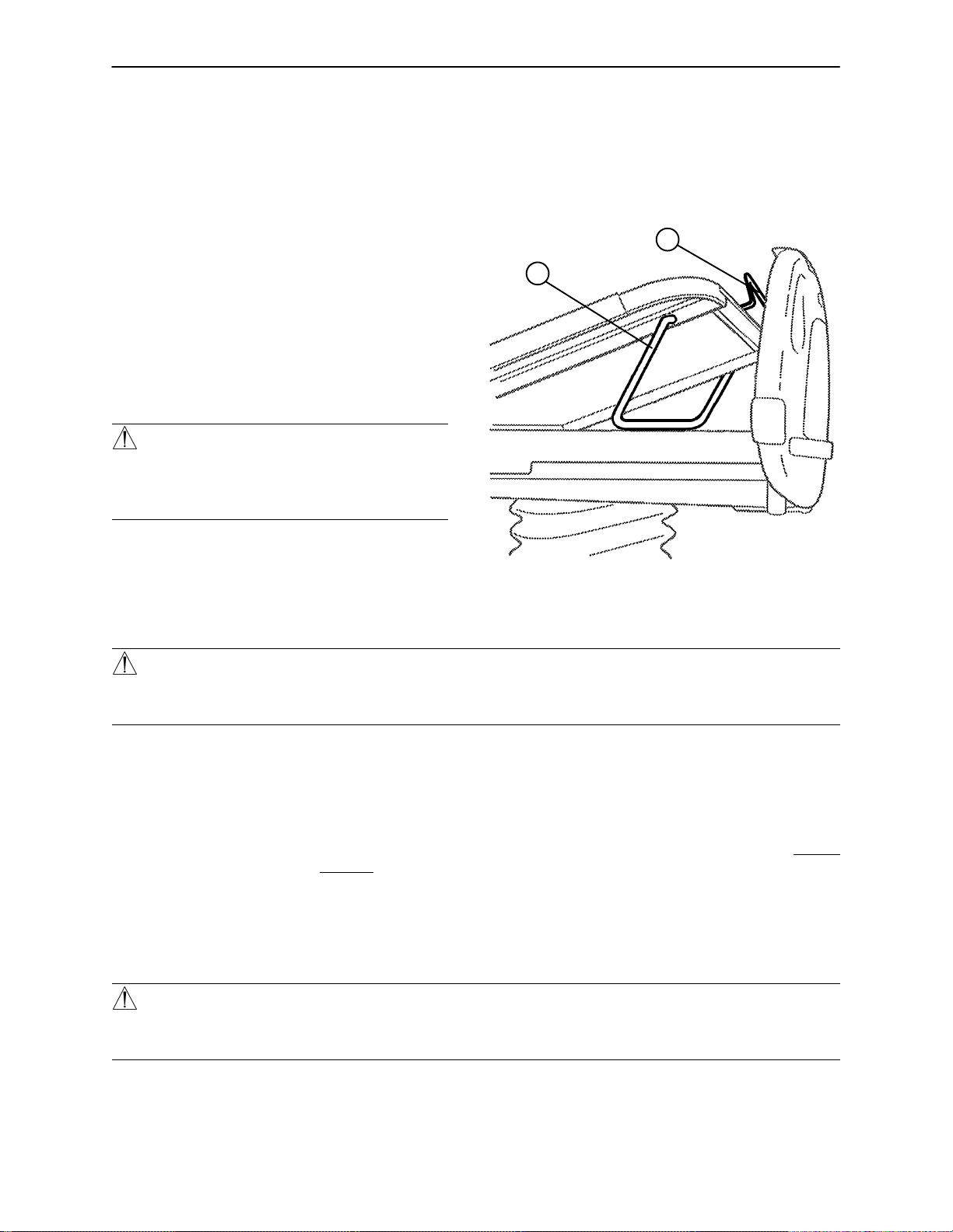
FOOT PROP USAGE
To prop the foot end of the Knee Gatch up, grasp
the handle (A) at the end of the Knee Gatch and
lift upward, allowing the foot prop (B) to engage at
the desired height. To release the prop, lift up on
the handle (A), swing the prop (B) toward the head
end of the bed to disengage the hinge and lower
the foot end.
WARNING
To avoid injury while cleaning or servicing under
the foot section, secure the foot section with string
or bungee cords or hold it up out of the way.
B
FOOT END
FRACTURE FRAME USAGE
A standard fracture frame can be mounted on the bed using the I.V. sockets located on all four corners of
the bed. I.V . poles can be used in conjunction with a fracture frame if I.V. pole adaptor sockets are purchased.
WARNING
Use only retractable traction or fracture frames. Failure to use a retractable frame may result in injury to the
patient and/or damage to the equipment.
FOLEY BAG HOOKS USAGE
The standard Foley bag hooks are found at two locations on both sides of the frame: under the frame below
the seat section and at the extreme foot end of the frame. The optional isolated Foley bag hooks are located
at the foot end of the bed on top of the lift header. The patient weight reading on the scale system will not
be affected when the optional isolated Foley bag hooks are used.
PATIENT RESTRAINT STRAP LOCATIONS
The bed has 12 locations for installing patient restraint straps on the litter top, 6 on each side of the bed.
WARNING
Improperly adjusted restraint straps can cause serious injury to a patient. The clinician must use her/his
judgement to determine proper use of restraint straps and restraint strap locations.
Clean Velcro AFTER EACH USE. Saturate Velcro with disinfectant and allow disinfectant to evaporate. (Appropriate disinfectant for nylon Velcro should be determined by the hospital.)
15
Litter Operation Guide
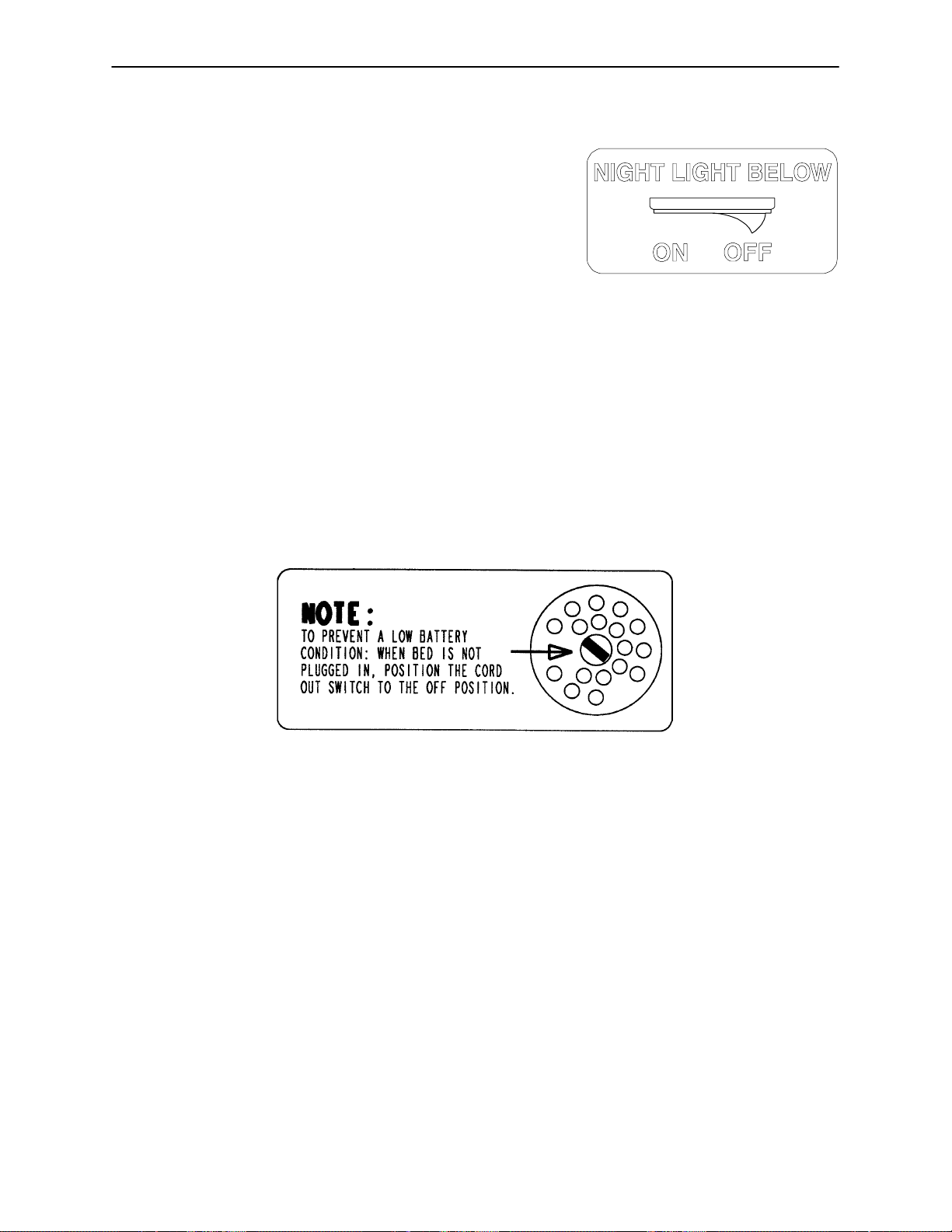
NIGHT LIGHT USAGE
The bed is equipped with two night lights to illuminate the
floor area around the bed.
There is a switch under the litter thigh section on the patient’s left side that turns both lights on and off.
NOTE
The night lights have sensors so the lights will turn off, even
when the switch is on, if the light in the room is bright
enough so a night light is not necessary.
NURSE CALL BACK–UP BATTERY (Optional Equipment)
To prevent a low battery condition when the bed is not plugged in, position the cord out switch at the head
end of the bed to the off position. The switch is identified by the label shown below. If the switch is not positioned as shown below and the bed power cord and pendant cord are unplugged, the life of the back–up battery will be significantly reduced.
If the power light (located on the foot board) is flashing, the Nurse Call battery needs to be replaced. The
battery is located on the patient’s left side at the head end of the bed. No tools are required to replace the
battery. Unplug the bed power cord from the wall socket and replace the battery.
CPR BOARD USAGE (Optional Equipment)
If the bed is equipped with the optional CPR board, it is stored on the bed’s head board. To remove it,
pull it away from the head board and lift it out of storage position. If the CPR board option was not purchased, the head board can also be removed and used as an emergency CPR board.
16
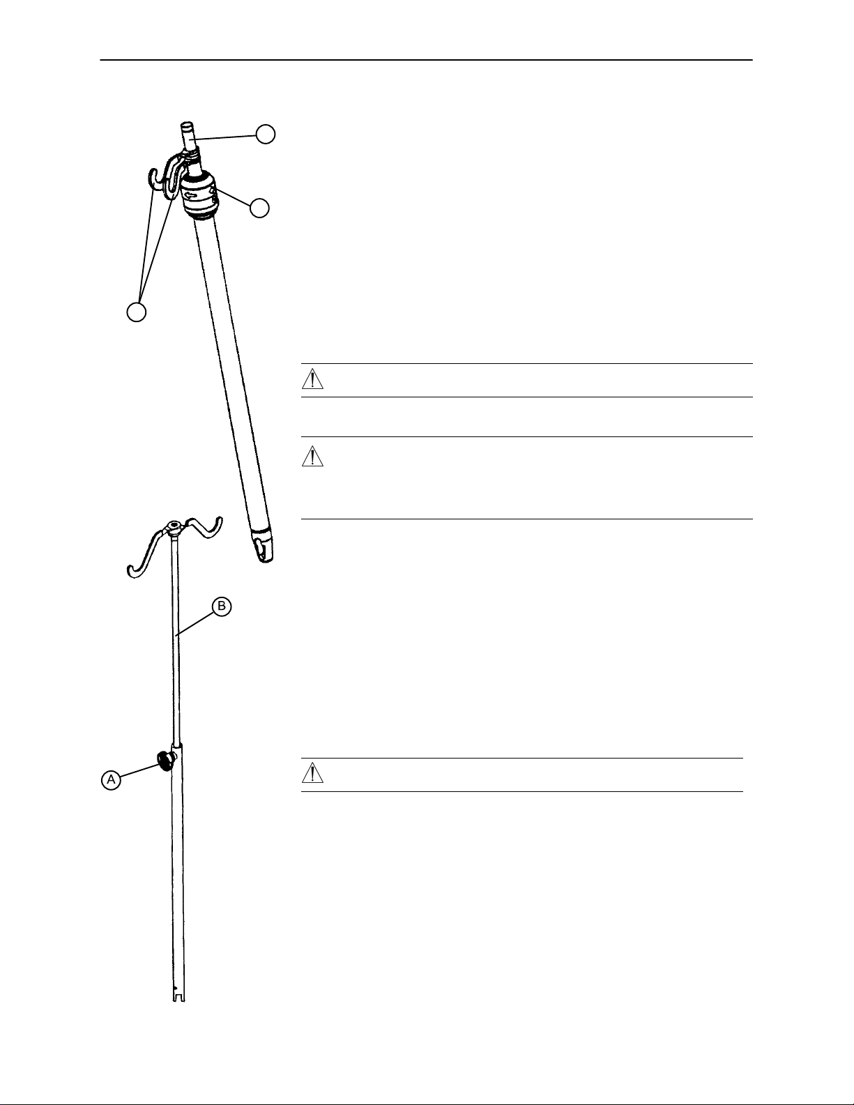
OPERATING I.V. POLES
A
C
B
Litter Operation Guide
To use the 2–Stage Permanently Attached I.V. pole:
NOTE
The 2–stage permanently attached I.V. pole is an option and may have been
installed at either the head, foot or both ends. The choice was made at the
time the unit was purchased.
1. Lift and pivot the pole from the storage position and push down until it
rests in the receptacle.
2. To raise the height of the pole, pull up on the telescoping portion (A) until
it locks into place at its fully raised position.
3. Rotate the I.V. hangers (B) to desired position and hang I.V. bags.
4. To lower the I.V. pole turn the latch (C) clockwise until section (A) lowers.
CAUTION
The weight of the I.V. bags should not exceed 40 pounds.
WARNING
To avoid pinching your fingers, place the I.V. pole in the upright position before using the drive handle .
To use the ”Removable” I.V. pole:
1. Install the pole at any of the four receptacles on the bed top (located on
all four corners of the frame.)
2. To raise the height of the pole, turn knob (A) counterclockwise and pull
up on the telescoping portion (B) of the pole and raise it to the desired height.
3. Turn knob (A) clockwise to tighten the telescoping portion in place.
CAUTION
The weight of the I.V. bags should not exceed 40 pounds.
17
Siderail Operation Guide
POSITIONING SIDERAILS
NOTE
The siderails can be locked at two heights (intermediate & full up).
The siderails can be tucked away under the bed when not in use. T o remove the rail from the tucked position,
grasp the top of the rail and pull outward.
To engage the head end siderail, grasp the rail and swing it upward to full height. When the siderail is being
raised, it does not lock in the intermediate position. To lower the siderail, push in the blue release handle (A)
and rotate the siderail until it locks in the intermediate position. To lower the siderail fully, push in the blue
release handle (A) again and rotate the siderail until it is completely lowered.
To engage the foot end siderail, the same procedure is required as for the head end siderail, however, the
siderail swings toward the foot end of the bed.
WARNING
Be sure the siderail is locked securely into position. Siderails are
not intended to keep patients
from exiting the bed. They are
designed to keep a patient
from inadvertently rolling off
the bed. Proper restraint
methods should be utilized to
ensure the patient remains in bed.
The siderails are not intended to be
used as a push device.
A
To disengage the rail, push in the blue release handle (A) and swing the rail down to the desired height. Store
the siderails by tucking the rails under the bed. Rails must be in the full down position before they can be
tucked.
SIDERAIL CONTROL PANEL LIGHTS
The bed is equipped with lights to illuminate the head end siderail control panel and the red nurse call
switches. Both can be activated at the foot board control panel. Three settings are available for the control
panel lights: low, medium and high intensity. When all lights are off, push the siderail control light button at
the foot board once to turn on both the control lights and the nurse call light at the siderail. Push again to
change from low to medium setting, and a third time to change to the high setting. The nurse call light intensity
is not affected. Pushing the button a fourth time will turn off the siderail control panel lights and pushing it
a fifth time will turn off the red nurse call light as well (see control panel guide page 21).
NOTE
The purpose of the red nurse call light on the siderails is to ensure the patient immediately knows which button
to push to contact the nurse station. Turning the red light of f may compromise this ability, especially in a darkened room.
18
Siderail Operation Guide
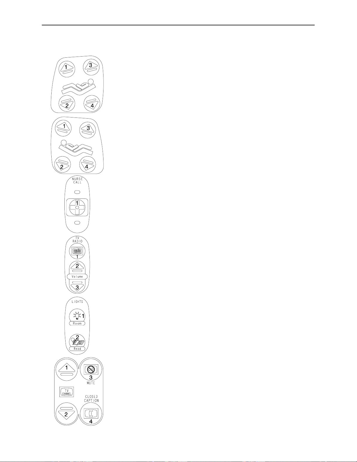
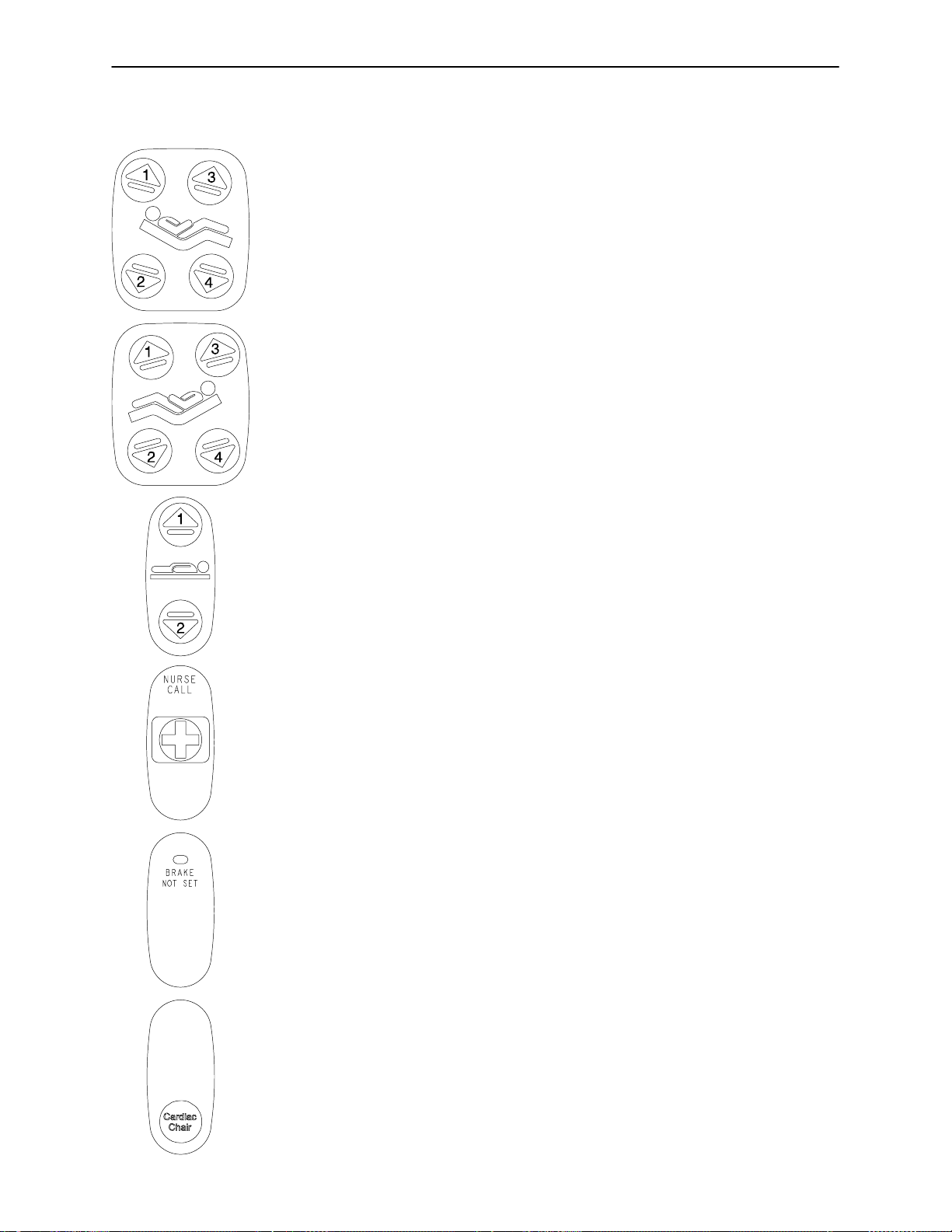
INSIDE SIDERAIL FUNCTION GUIDE
(Patient’s Right Rail)
1. Push to raise Knee Gatch.
2. Push to lower Knee Gatch.
3. Push to raise Fowler.
4. Push to lower Fowler.
(Patient’s Left Rail)
1. Push to raise Fowler.
2. Push to lower Fowler.
3. Push to raise Knee Gatch.
4. Push to lower Knee Gatch.
1. Push to activate Nurse Call.
NOTE
Yellow LED will light when button is pushed. Red LED will light with
Nurse Station acknowledgment.
This panel is optional equipment.
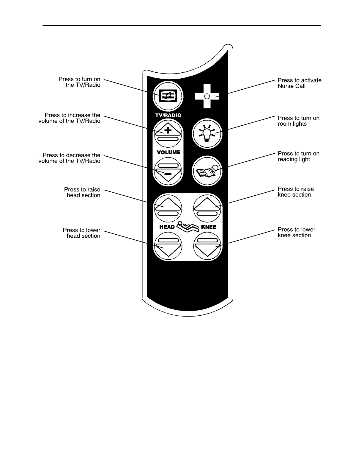
1. Push to turn TV or radio on and to select a channel.
2. Push to increase volume.
3. Push to decrease volume.
This panel is optional equipment.
1. Push to turn the room light on.
2. Push to turn the bed overhead light on.
This panel is optional equipment.
1. Push to change the TV channel up.
2. Push to change the TV channel down.
3. Push to mute TV volume. Push again to turn the sound back on.
4. Push to display closed captioning. Push again to turn off closed captioning.
This panel is optional equipment.
19
Siderail Operation Guide
OUTSIDE SIDERAIL FUNCTION GUIDE
(Patient’s Right Rail)
1. Push to raise Fowler.
2. Push to lower Fowler.
3. Push to raise Knee Gatch.
4. Push to lower Knee Gatch.
This panel is optional equipment.
(Patient’s Left Rail)
1. Push to raise Knee Gatch.
2. Push to lower Knee Gatch.
3. Push to raise Fowler.
4. Push to lower Fowler.
This panel is optional equipment.
1. Push to raise bed height.
2. Push to lower bed height.
Push to activate Nurse Call.
This panel is optional equipment.
LED will blink when the brakes are not set.
Push to activate the Cardiac Chair function. The Knee will raise, the
Back will raise or lower to approximately 52 and the bed will tilt to
approximately –12 reverse Trendelenburg (foot end down). Release
the button to stop bed movement: hold the button until movement stops
to complete the function.
This panel is optional equipment.
20
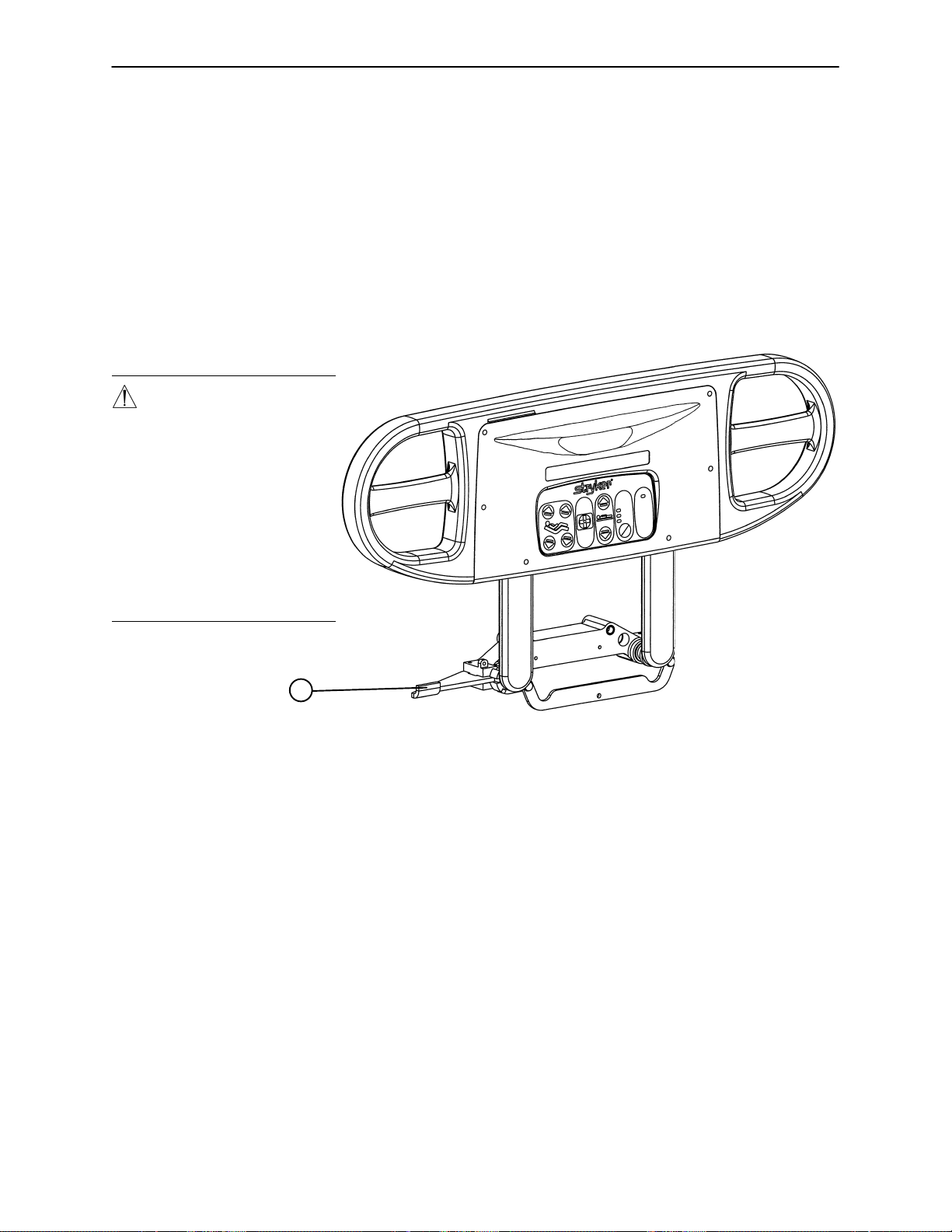
Foot Board Operation Guide
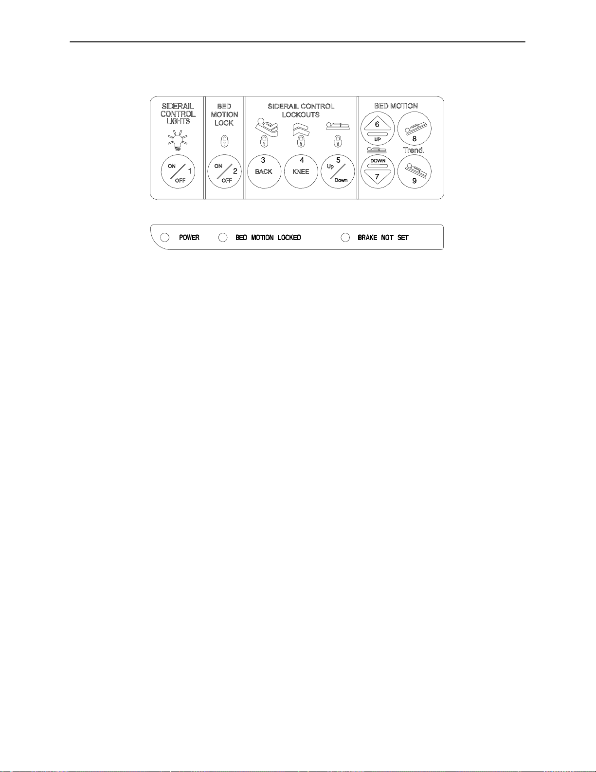
FOOT BOARD CONTROL PANEL GUIDE
1. Push repeatedly for low, medium and high settings for the siderail control panel lights. Pushing a fourth
and fifth time will turn off the siderail lights and the red nurse call light respectively (see page 18).
NOTE
The intent of the red nurse call light on the siderails is to ensure the patient immediately knows which button
to push to contact the nurse station. Turning the red light off may compromise this ability, especially in a darkened room.
2. Push to lock out all bed motions. The MOTION lock icon and the “BED MOTION LOCKED” LED will light.
Push again to unlock.
3. Push to lock out Back Rest controls at both siderails. The HEAD lock icon will light. Push again to unlock.
4. Push to lock out Knee Gatch controls at both siderails. The KNEE lock icon will light. Push again to unlock.
5. Push to lock out bed height movement at both siderails. The UP/DOWN lock icon will light. Push again
to unlock.
6. Push to raise bed height.
7. Push to lower bed height.
8. Push to lower head end/raise foot end of bed (Trendelenburg position).
9. Push to lower foot end/raise head end of bed (Reverse Trendelenburg position).
FUNCTION LOCKOUT SYSTEM USAGE
1. To lock out the bed movement functions on the siderails and prevent the patient from changing the position-
ing of the bed, push the ”HEAD”, ”KNEE” and/or ”UP/DOWN” switches in the ”Siderail Control Lockouts”
module on the foot board control panel.
NOTE
The foot board controls for these motions are not affected by the lockout switches.
The ”padlock” symbol on the control panel will be lighted when that function is locked out.
2. To lock out the entire bed motion for all switches on the bed (siderails and foot board), push the ”ON/OFF”
switch in the ”Bed Motion Lock” module on the foot board control panel.
21

Foot Board Operation Guide
FOOT BOARD CONTROL PANEL GUIDE (CONTINUED)
1. Push to raise Fowler.
2. Push to raise Knee Gatch.
3. Push to lower Fowler.
4. Push to lower Knee Gatch.
This panel is optional equipment.
LED DISPLAY PANEL GUIDE
The LED Display Panel is located at the foot end of the bed, under the Control Panel.
”POWER” – will light when the bed is plugged into the wall receptacle. Will blink if the 9V Nurse Call battery
needs to be replaced.
”BED MOTION LOCKED” – will light when the Bed Motion Lock has been activated.
”BRAKE NOT SET” – will blink when the brakes have not been set.
”BED EXIT ON” – will light when the Bed Exit function has been activated (optional equipment).
22
Foot Board Operation Guide
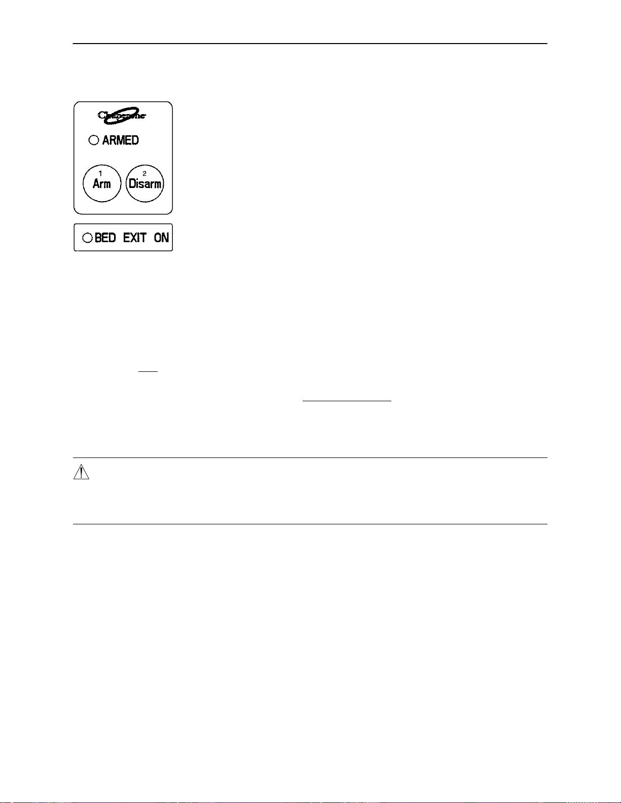
CHAPERONE BED EXIT (OPTIONAL EQUIPMENT)
1. Push to activate Bed Exit function.
2. Push to deactivate Bed Exit function.
NOTE
If the scale system is in use, it will switch to ”off” when Bed Exit is armed. When the bed is equipped with
scales, the scales must be properly zeroed for the Bed Exit System to function properly (see page 27 for scale
system usage instructions). If bed is not equipped with a scale system, follow the procedure below.
1. Before putting a new patient on the bed: prepare bed for patient stay by adding linens and equipment to
the bed.
2. Press and hold the ”ARM” and the ”DISARM” keys together for 5 seconds. The ”ARMED” light will begin
to flash.
3. Release the ”ARM” and the ”DISARM” keys and do not touch the bed until the ”ARMED” light stops flash-
ing.
4. Once the new patient is on the bed: push and release the ”ARM” key (”ARMED” light will come on).
5. To deactivate Bed Exit, push ”DISARM”. The ”ARMED” and ”BED EXIT ON” LED’s will turn off.
WARNING
The Bed Exit System is intended only to aid in the detection of a patient exiting the bed. It is NOT intended
to replace patient monitoring protocol. It signals when a patient is about to exit. Adding or subtracting objects
from the bed after arming the bed exit system may cause a reduction in the sensitivity of the bed exit system.
23
Foot Board Operation Guide
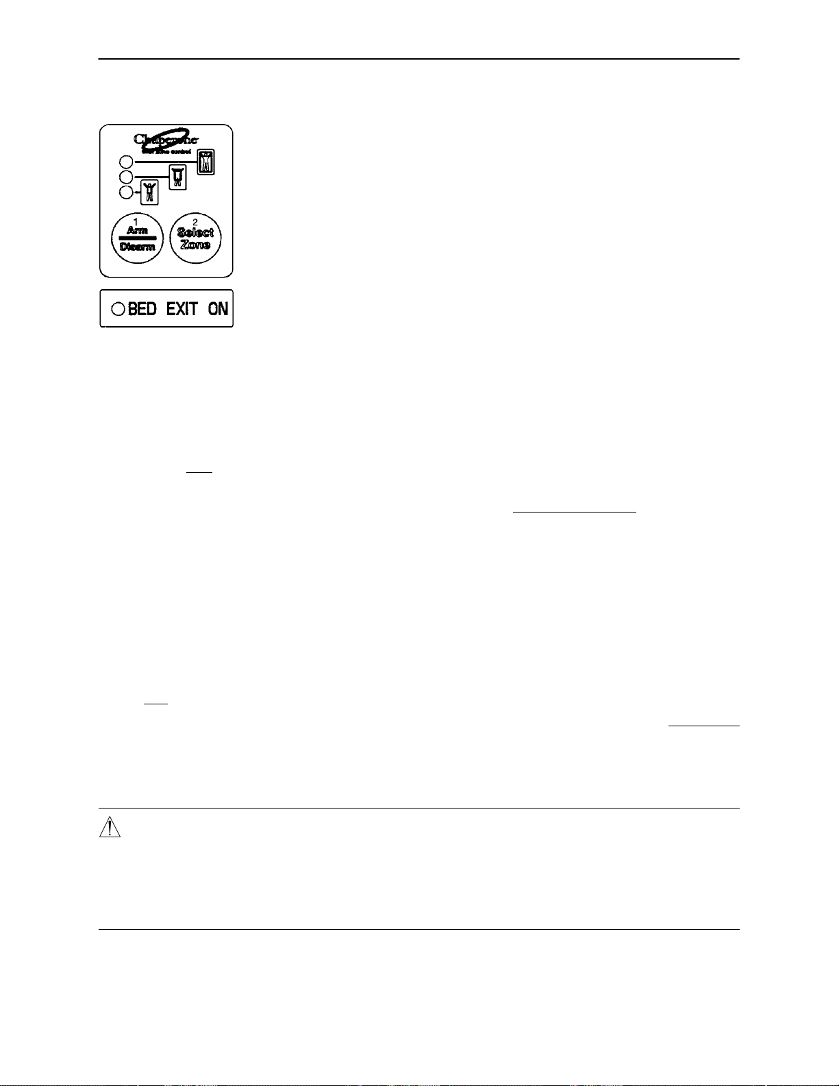
CHAPERONE II BED EXIT WITH ZONE CONTROL (OPTIONAL EQUIPMENT)
NOTE
If the scale system is in use, it will switch to ”off” when Bed Exit is armed. When the bed is equipped with
scales, the scales must be properly zeroed for the Bed Exit System to function properly (see page 27 for scale
system usage instructions). If bed is not equipped with a scale system, follow the procedure below.
1. Before putting a new patient on the bed: prepare bed for patient stay by adding linens and equipment to
the bed.
2. Press and hold the ”ARM/DISARM” and the ”SELECT ZONE” keys together for 5 seconds. The top LED
will begin to flash.
3. Release the ”ARM/DISARM” and the ”SELECT ZONE” keys and do not touch the bed until the top LED
stops flashing.
4. Once the new patient is on the bed: push and release the ”ARM/DISARM” key (top LED will come on).
5. The Bed Exit system with Zone Control will automatically select the first zone. To change the zone, push
and hold the “SELECT ZONE” key until the LED indicating the desired zone comes on.
6. To deactivate Bed Exit, push the ”ARM/DISARM” key. The selected zone LED and ”BED EXIT ON” LED
will turn off.
CHAPERONE II ZONE SETTINGS
The first zone (top LED) is the traditional Bed Exit zone. The patient can move around the bed freely but
cannot fully exit the bed or the alarm will sound.
The second zone (middle LED) is more restrictive. It allows the patient to sit up and roll over but any attempt
to exit the bed will cause the alarm to sound.
The third zone (bottom LED) is the most movement restrictive zone. Small movements like raising an arm
or lifting the shoulders off the bed will cause the alarm to sound. The third zone is used to alert staf f to a change
in the condition of an unconscious or paralyzed patient.
WARNING
The Bed Exit System is intended only to aid in the detection of a patient exiting the bed. It is NOT intended
to replace patient monitoring protocol. It signals when a patient is about to exit. Adding or subtracting objects
from the bed after arming the bed exit system may cause a reduction in the sensitivity of the bed exit system.
Failure to set the Chaperone zone properly could result in improper monitoring and patient injury . Verify the
proper zone is selected before leaving the patient.
24

Foot Board Operation Guide
WEIGH SYSTEM CONTROL PANEL GUIDE
1
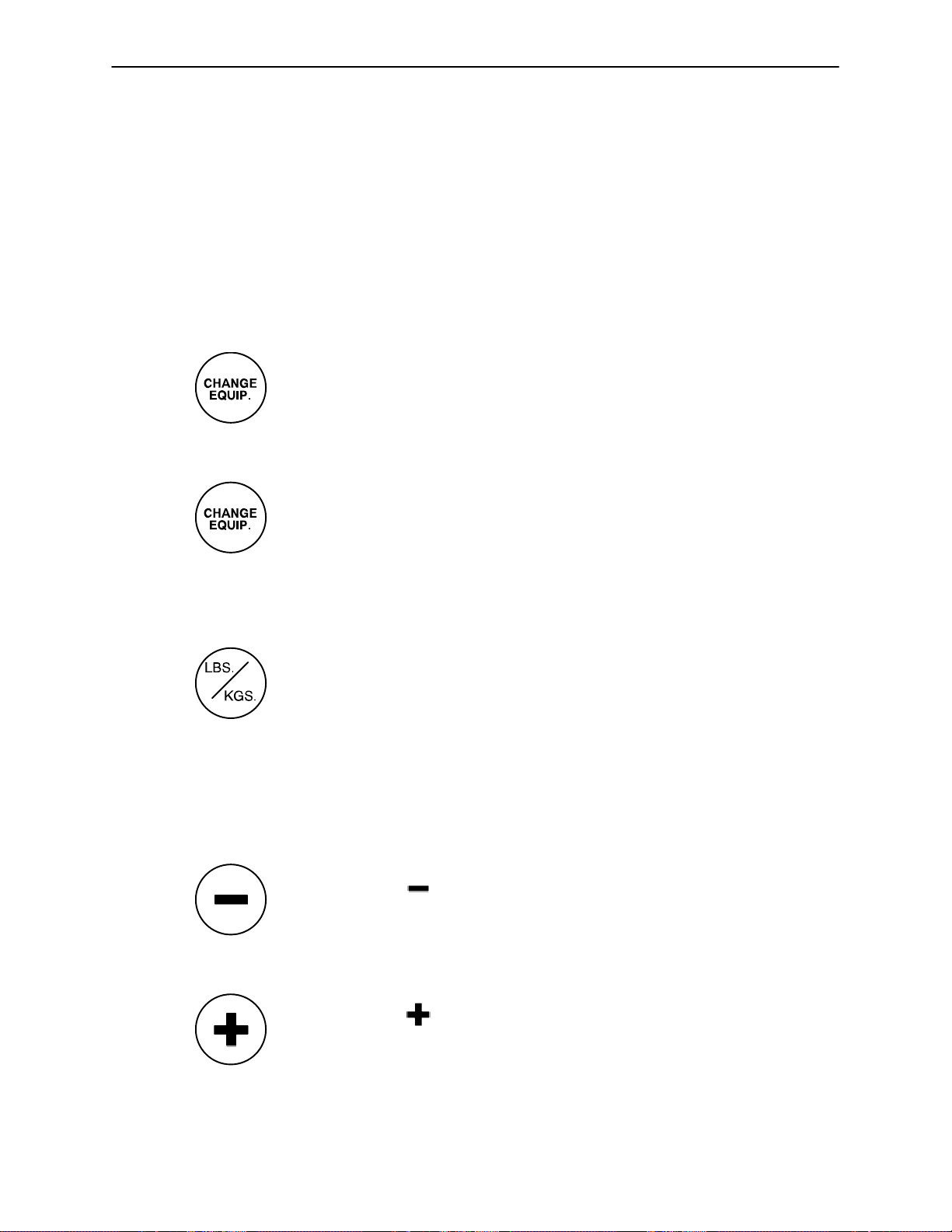
1. Display – displays patient weight and other information.
2. Push to zero bed.
3. Push when changing equipment on the bed.
4. Push to change weight from pounds to kilograms or back.
5. Push to turn weight system on.
6. Push to decrease numerical value of displayed weight.
7. Push to increase numerical value of displayed weight.
NOTE
After approximately 30 seconds of idle time, the scale display will turn off and will show the Trendelenburg
angle of the bed. Press “SCALE ON” to return to the weight display.
SYMBOL ACTION DISPLAY
To prepare bed for new patient:
Release the button after the ”WEIGHING...”
SCALE
ON
ZERO
Press and hold ”SCALE ON”. ”LET GO FOR SCALE”
display reads: ”XXX.X LB”
”LET GO FOR SCALE”
Press and hold ”ZERO””HOLD TO ZERO WT.”
”RELEASE TO ZERO”
Release ”ZERO””DO NOT TOUCH BED”
”0.0 LB”
25
Foot Board Operation Guide
WEIGH SYSTEM CONTROL PANEL GUIDE (CONTINUED)
SYMBOL ACTION DISPLAY
To add or remove equipment
during patient stay without
affecting registered patient
weight:
Press and release ”SCALE ON””WEIGHING...”
Press “CHANGE EQUIP.” ”HOLD TO START”
Release “CHANGE EQUIP””DO NOT TOUCH BED”
Add or remove equipment.
”XXX.X LB”
”RELEASE TO START”
”ADD/REMOVE EQUIP.”
Press “CHANGE EQUIP” ”RELEASE TO FIN.”
Release “CHANGE EQUIP””DO NOT TOUCH BED”
To convert the patient’s weight:
To convert the patient’s weight ”WEIGHT NOW KGS”
to kilograms, press and release ”XXX.X KG”
”LBS./KG.”
Repeat the procedure to return to
pounds.
To change the numerical value
of displayed weight:
Press and hold to scroll to ”HOLD TO DEC. WT.”
desired weight. ”XXX.X LB”
”XXX.X LB”
Press and hold to scroll to ”HOLD TO INC. WT.”
desired weight. ”XXX.X LB”
26

Weigh System Usage
OPERATING THE SCALE BEFORE PUTTING A NEW PATIENT ON THE BED
Prepare the bed for a patient stay (linens, pillows, etc.).
Press and hold ”SCALE ON”. Release the button after the display reads ”LET GO FOR SCALE”. (This
will turn off the Trend. angle display and activate the scale). The display will read:
”LET GO FOR SCALE”
”WEIGHING”
”XXX.X LB”
Press and hold ”ZERO”. The display will read:
”HOLD TO ZERO WT.”
”RELEASE TO ZERO”
Release ”ZERO”. The display will now read:
”DO NOT TOUCH BED”
”0.0 LB”
The bed is now ready for the patient.
NOTE
Do not zero the bed while a patient is on the bed. An inaccurate patient weight reading will result. If this should
occur, remove the patient from the bed and zero the bed again.
OPERATING THE SCALE IF A PATIENT IS ALREADY ON THE BED
If it is necessary to add or remove special equipment (monitors, pumps, etc.) during the patient’s
stay, press and release ”SCALE ON” to activate the weigh system. After the display reads ”XXX.X
LB”, press and hold “CHANGE EQUIP.”. The display will read:
”HOLD TO START”
”RELEASE TO START”
Release “CHANGE EQUIP.”. The display will read:
”DO NOT TOUCH BED”
”ADD/REMOVE EQUIP”
Add or remove the equipment and press “CHANGE EQUIP.”. The display will read:
”RELEASE TO FIN.”
Release “CHANGE EQUIP.”. The display will read:
”DO NOT TOUCH BED”
”XXX.X LB”
The weight displayed will be that of the patient only.
27

Weigh System Usage
CONVERTING THE PATIENT’S WEIGHT
To convert the patient’s weight from pounds to kilograms, press and release ”SCALE ON” to activate
the weigh system. After the display reads ”XXX.X LB”, press and release the ”LBS/KGS” button.
The display will read:
”WEIGHT NOW KGS”
”XXX.X KG”
Repeat the procedure to return to pounds. The display will read:
”WEIGHT NOW LBS”
”XXX.X LB”
CHANGING THE NUMERICAL VALUE OF THE DISPLAYED WEIGHT
To decrease the numerical value of the displayed weight, press and hold ”–”. The display will read:
”HOLD TO DEC. WT.”
”XXX.X LB”
Hold ”–” until desired value is achieved.
To increase the numerical value of the displayed weight, press and hold ”+”. The display will read:
”HOLD TO INC. WT.”
”XXX.X LB”
Hold ”+” until desired value is achieved.
NOTE
The weigh system will shut off approximately one minute after a function has been used, if another function
is not activated. The display light will shut off and the display will read ”SCALE OFF”.
The weigh system will retain all patient weight information in its memory even when the display is off or when
the bed is unplugged from the wall socket.
28
Optional Pendant Operation
29
 Loading...