


 Loading...
Birthing Bed
Model LD304
Maintenance Manual
For Parts or
USA: 1-800-327-0770 (option 2)
Canada: 1-888-233-6888
2007/01 |
4701-109-002 REV C |
www.stryker.com |

Table of Contents
Introduction . . . . . . . . . . . . . . . . . . . . . . . . . . . . . . . . . . |
. . |
. |
. |
. |
7 |
Intended Use . . . . . . . . . . . . . . . . . . . . . . . . . . . . . . . |
. . |
. |
. |
. |
. 7 |
Product Description . . . . . . . . . . . . . . . . . . . . . . . . . . . . . |
. . . . . 7 |
||||
Product Illustration . . . . . . . . . . . . . . . . . . . . . . . . . . . . . . . . . . . 7 |
|||||
Specifications . . . . . . . . . . . . . . . . . . . . . . . . . . . . . . . |
. . |
. |
. |
. |
. 8 |
Warning / Caution / Note Definition . . . . . . . . . . . . . . . . . . . . . . . |
. . |
. |
. |
. |
. 9 |
Symbols . . . . . . . . . . . . . . . . . . . . . . . . . . . . . . . . . . . |
. . |
. |
. |
. |
10 |
Summary of Safety Precautions . . . . . . . . . . . . . . . . . . . . . . . . . . |
. . |
. |
. |
. |
11 |
Safety Tips and Guidelines . . . . . . . . . . . . . . . . . . . . . . . . . . |
. . |
. |
. |
. |
11 |
Preventative Maintenance . . . . . . . . . . . . . . . . . . . . . . . . . . . . |
. . . . . 13 |
||||
Cleaning . . . . . . . . . . . . . . . . . . . . . . . . . . . . . . . . . . . . . . . . 14 |
|||||
Troubleshooting Guide . . . . . . . . . . . . . . . . . . . . . . . . . . . . . . |
. . |
. |
. |
. 15 |
|
Quick Reference Replacement Parts List . . . . . . . . . . . . . . . . . . . . . . . . . . . . 21 |
|||||
Electrical Service Information . . . . . . . . . . . . . . . . . . . . . . . . . . . |
. . |
. |
. |
. 23 |
|
Bed Circuit Boards - CPU Board - 3002-407-950 . . . . . . . . . . . . . . . . . . |
. . |
. |
. |
. |
23 |
Bed Circuit Boards - Software Configuration . . . . . . . . . . . . . . . . . . . . |
. . |
. |
. |
. 25 |
|
Bed Circuit Boards - Power Supply - 0059-157-000 . . . . . . . . . . . . . . . . . |
. . |
. |
. |
. |
26 |
Bed Circuit Boards - Foot Power Board - 4701-080-053 . . . . . . . . . . . . . . . . |
. . |
. |
. |
. 27 |
|
Optional Bed Communications Tester - 3002-045-700 . . . . . . . . . . . . . . . . |
. . |
. |
. |
. |
28 |
Head Wall Output Configuration . . . . . . . . . . . . . . . . . . . . . . . . |
. . |
. |
. |
. |
29 |
Service Information . . . . . . . . . . . . . . . . . . . . . . . . . . . . . . . |
. . |
. |
. |
. 30 |
|
Static Discharge Precautions . . . . . . . . . . . . . . . . . . . . . . . . . |
. . |
. |
. |
. |
30 |
CPU Board Replacement (3002-407-950) . . . . . . . . . . . . . . . . . . . . . |
. . |
. |
. |
. 31 |
|
Power Supply Replacement (0059-157-000) . . . . . . . . . . . . . . . . . . . . |
. . |
. |
. |
. |
31 |
Foot Power Board Replacement (4701-080-053) . . . . . . . . . . . . . . . . . . |
. . |
. |
. |
. |
32 |
Brake Adjustment . . . . . . . . . . . . . . . . . . . . . . . . . . . . . . |
. . |
. |
. |
. 32 |
|
Bed Lift Motor Replacement (120V - 4701-700-005) . . . . . . . . . . . . . . . . . |
. . |
. |
. |
. |
33 |
Trendelenburg Motor Replacement (120V - 4701-032-095) . . . . . . . . . . . . . . . |
. . . . . 34 |
||||
Fowler Motor Replacement (120V - 4701-035-040) . . . . . . . . . . . . . . . . . . . . . . 36 |
|||||
Fowler Ball Screw Replacement (4701-035-012) . . . . . . . . . . . . . . . . . . |
. . |
. |
. |
. |
37 |
Skoocher™ Motor Replacement . . . . . . . . . . . . . . . . . . . . . . . . |
. . |
. |
. |
. |
38 |
Foot Motor Replacement (120V - 4701-040-035 / 230V - 4712-040-035) . . . . . . . . . |
. . |
. |
. |
. |
39 |
Optional Air Mattress Compressor Replacement (120V - 4701-048-015 / 230V - 4712-048-015) . |
. . |
. |
. |
. 40 |
|
Night Light Replacement (4701-080-080) . . . . . . . . . . . . . . . . . . . . . |
. . |
. |
. |
. |
41 |
Nurse Call 9V Battery Replacement . . . . . . . . . . . . . . . . . . . . . . . |
. . |
. |
. |
. |
41 |
Diagnostics Mode . . . . . . . . . . . . . . . . . . . . . . . . . . . . . . |
. . |
. |
. |
. 41 |
|
Foot Potentiometer Replacement . . . . . . . . . . . . . . . . . . . . . . . . |
. . |
. |
. |
. |
42 |
Foot Potentiometer Burn-In Procedure . . . . . . . . . . . . . . . . . . . . . . |
. . . . . 43 |
||||
Fowler Potentiometer Replacement (4701-080-025) . . . . . . . . . . . . . . . . . . . . . . 44 |
|||||
Fowler Potentiometer Burn-In Procedure . . . . . . . . . . . . . . . . . . . . . |
. . |
. |
. |
. |
44 |
Lift Potentiometer Replacement (4701-080-025) . . . . . . . . . . . . . . . . . . . . . . . . . . . . . . . . . . . . . |
. . . . |
. . |
. . |
. . 45 |
|
Lift Potentiometer Burn-In Procedure . . . . . . . . . . . . . . . . . . . . . . . |
. . |
. |
. |
. 45 |
|
Smart TV Interface Burn-in Procedure . . . . . . . . . . . . . . . . . . . . . . |
. . |
. |
. |
. |
46 |
www.stryker.com |
4701-109-002 REV C |
|

Table of Contents
Asembly Drawings |
|
|
|
6” Caster/Base Assembly . . . . . . . . . . . |
. . . . . . . . . . . . . . . . . . . . |
|
. 47 |
8” Caster/Base Assembly . . . . . . . . . . . |
. . . . . . . . . . . . . . . . . . . . |
|
. 48 |
6” Caster Assembly - 3001-200-060 . . . . . . . |
. . . . . . . . . . . . . . . . . . . . |
|
. 49 |
6” Steer Caster Assembly - 3001-200-050 . . . . . |
. . . . . . . . . . . . . . . . . . . . |
|
. 50 |
6” Molded Wheel Assembly - 5000-002-010 . . . . |
. . . . . . . . . . . . . . . . . . . . . 51 |
||
Optional 8” Caster Assembly - 3001-200-090 . . . . . . . . . . . . . . . . . . . . . . . . 52 |
|||
Optional 8” Steer Caster Assembly - 3001-200-080 . . |
. . . . . . . . . . . . . . . . . . . |
. |
53 |
Optional 8” Wheel Assembly - 0715-002-025 . . . . |
. . . . . . . . . . . . . . . . . . . . |
|
. 54 |
Base Assembly . . . . . . . . . . . . . . . |
. . . . . . . . . . . . . . . . . . . . |
|
. 55 |
Head End Brake Assembly, Right . . . . . . . . . |
. . . . . . . . . . . . . . . . . . . |
. |
60 |
Head End Brake Assembly, Left . . . . . . . . . |
. . . . . . . . . . . . . . . . . . . |
. |
61 |
Foot End Brake Assembly, Right . . . . . . . . . |
. . . . . . . . . . . . . . . . . . . |
. |
62 |
Foot End Brake Assembly, Left . . . . . . . . . |
. . . . . . . . . . . . . . . . . . . . |
|
. 63 |
Litter Lift/Trend Assembly . . . . . . . . . . . |
. . . . . . . . . . . . . . . . . . . . |
|
. 64 |
Litter/Lift/Trend Standard Components . . . . . . |
. . . . . . . . . . . . . . . . . . . . |
|
. 69 |
Domestic Trend Motor Assembly . . . . . . . . . |
. . . . . . . . . . . . . . . . . . . |
. |
74 |
International Trend Motor Assembly . . . . . . . . |
. . . . . . . . . . . . . . . . . . . |
. |
76 |
Bed Lift Motor Assembly . . . . . . . . . . . . |
. . . . . . . . . . . . . . . . . . . |
. |
79 |
Bed Lift Standard Components . . . . . . . . . |
. . . . . . . . . . . . . . . . . . . . |
|
. 80 |
Foot Lift Assembly . . . . . . . . . . . . . . |
. . . . . . . . . . . . . . . . . . . |
. |
85 |
Foot Lift Assembly Standard Components . . . . . |
. . . . . . . . . . . . . . . . . . . . |
|
. 86 |
Litter Assembly . . . . . . . . . . . . . . . |
. . . . . . . . . . . . . . . . . . . . |
|
. 89 |
Seat Assembly . . . . . . . . . . . . . . . |
. . . . . . . . . . . . . . . . . . . . |
|
101 |
Left Hand Grip Assembly - 5010-230-061 . . . . . |
. . . . . . . . . . . . . . . . . . . . |
|
102 |
Right Hand Grip Assembly - 5010-230-060 . . . . . . . . . . . . . . . . . . . . . . . . . 103 |
|||
Bellows Cover Assembly - 4701-030-130 . . . . . . |
. . . . . . . . . . . . . . . . . . . |
. 104 |
|
Plastic Fluid Basin - 4701-036-001 . . . . . . . . |
. . . . . . . . . . . . . . . . . . . |
. 105 |
|
Night Light Option Assembly - 4701-036-201 . . . . |
. . . . . . . . . . . . . . . . . . . . |
|
106 |
Foot Positioning Assembly . . . . . . . . . . . . . . . . . . . . . . |
. . . . . . . . . . . . . . . . . . . . . . . . . . . . . . . . . . . . . . . |
. |
108 |
Foot Positioning Subassembly, Left . . . . . . . . |
. . . . . . . . . . . . . . . . . . . |
. |
110 |
Foot Positioning Subassembly, Right . . . . . . . |
. . . . . . . . . . . . . . . . . . . . |
|
112 |
Foot Lift Casting Subassembly - 4701-040-205 . . . |
. . . . . . . . . . . . . . . . . . . . |
|
114 |
Skoocher™ Option Assembly . . . . . . . . . . |
. . . . . . . . . . . . . . . . . . . |
. |
115 |
Non-Skoocher™ Option . . . . . . . . . . . . |
. . . . . . . . . . . . . . . . . . . . |
|
120 |
Fowler Guide/Skoocher™ Standard Components . . . . . . . . . . . . . . . . . . . . . . . 122 |
|||
Domestic Fowler/Skoocher™ Motor - 4701-035-040 . . . . . . . . . . . . . . . . . . . . . . 130 |
|||
International Fowler/Skoocher™ Motor - 4712-035-040 |
. . . . . . . . . . . . . . . . . . . . |
|
130 |
Domestic Fowler Motor W/Clutch . . . . . . . . |
. . . . . . . . . . . . . . . . . . . . |
|
131 |
International Fowler Motor W/Clutch . . . . . . . |
. . . . . . . . . . . . . . . . . . . . |
|
131 |
Foot Section Assembly . . . . . . . . . . . . |
. . . . . . . . . . . . . . . . . . . . |
|
132 |
Foot Section Standard Components - 4701-040-005 . |
. . . . . . . . . . . . . . . . . . . . |
|
133 |
Sliding Block Assembly . . . . . . . . . . . . |
. . . . . . . . . . . . . . . . . . . . |
|
139 |
4701-109-002 REV C |
www.stryker.com |

Table of Contents
Assembly Drawings (Continued) |
|
|
Foot Mattress . . . . . . . . . . . . . . . . . . . . . . . . . . . . . . . . . . . |
. |
142 |
Enhanced Comfort Mattress Option . . . . . . . . . . . . . . . . . . . . . . . . . . . . 143 |
||
Enhanced Comfort Mattress . . . . . . . . . . . . . . . . . . . . . . . . . . . . . . |
|
144 |
Enhanced Comfort Mattress Standard Components . . . . . . . . . . . . . . . . . . . . . |
. 145 |
|
Air Mattress Option . . . . . . . . . . . . . . . . . . . . . . . . . . . . . . . . . |
. |
146 |
Air Mattress . . . . . . . . . . . . . . . . . . . . . . . . . . . . . . . . . . . . |
|
147 |
Optional Air Mattress Standard Components . . . . . . . . . . . . . . . . . . . . . . . . |
|
148 |
Air Mattress Compressor / Manifold Assembly . . . . . . . . . . . . . . . . . . . . . . . |
. 150 |
|
Left Upright Assembly . . . . . . . . . . . . . . . . . . . . . . . . . . . . . . . . |
. |
152 |
Right Upright Assembly . . . . . . . . . . . . . . . . . . . . . . . . . . . . . . . . |
|
155 |
Foot Assembly, Left & Right . . . . . . . . . . . . . . . . . . . . . . . . . . . . . . |
|
158 |
Upright Housing Assembly . . . . . . . . . . . . . . . . . . . . . . . . . . . . . . . |
|
159 |
Upright Housing . . . . . . . . . . . . . . . . . . . . . . . . . . . . . . . . . . |
. |
163 |
Foot Abduction Extrusion Assembly . . . . . . . . . . . . . . . . . . . . . . . . . . . |
. 164 |
|
Left Upright Slide Assembly . . . . . . . . . . . . . . . . . . . . . . . . . . . . . . |
|
166 |
Right Upright Slide Assembly . . . . . . . . . . . . . . . . . . . . . . . . . . . . . |
. 167 |
|
Left Abduction Assembly . . . . . . . . . . . . . . . . . . . . . . . . . . . . . . . |
. 168 |
|
Right Abduction Assembly . . . . . . . . . . . . . . . . . . . . . . . . . . . . . . . |
|
169 |
Abduction Assembly Standard Components . . . . . . . . . . . . . . . . . . . . . . . . |
. 170 |
|
No Calf Support Option - 4701-040-185 . . . . . . . . . . . . . . . . . . . . . . . . . . |
|
172 |
Attached Support Calf Option - 4701-840-290 . . . . . . . . . . . . . . . . . . . . . . . |
. 173 |
|
Right Attached Calf Support Assembly - 4701-840-270 . . . . . . . . . . . . . . . . . . . . |
|
174 |
Left Attached Calf Support Assembly - 4701-840-275 . . . . . . . . . . . . . . . . . . . . |
. 175 |
|
Removable Calf Support Option - 4701-840-295 . . . . . . . . . . . . . . . . . . . . . . |
. 176 |
|
Removable Calf Support Assembly, Right & Left . . . . . . . . . . . . . . . . . . . . . . |
. 177 |
|
No Optional Headwall Interface . . . . . . . . . . . . . . . . . . . . . . . . . . . . . |
|
178 |
Headwall Interface with Pendant Port/No Nurse Call . . . . . . . . . . . . . . . . . . . . . |
|
180 |
Headwall Interface with Nurse Call/No Pendant Port . . . . . . . . . . . . . . . . . . . . . |
|
182 |
Headwall Interface with Nurse Call & Pendant Port . . . . . . . . . . . . . . . . . . . . . |
. 184 |
|
Electrical Box Standard Components . . . . . . . . . . . . . . . . . . . . . . . . . . . |
|
186 |
Full Bed Electrical Assembly . . . . . . . . . . . . . . . . . . . . . . . . . . . . . . |
|
189 |
Left Siderail Assembly . . . . . . . . . . . . . . . . . . . . . . . . . . . . . . . . |
|
193 |
Standard Siderail Components, Left - 4701-020-085 . . . . . . . . . . . . . . . . . . . . . |
|
194 |
Right Siderail Assembly . . . . . . . . . . . . . . . . . . . . . . . . . . . . . . . |
. 198 |
|
Standard Siderail Components, Right - 4701-020-090 . . . . . . . . . . . . . . . . . . . . . 199 |
||
Siderail Latch Assembly, Left - 3002-400-070 . . . . . . . . . . . . . . . . . . . . . . . . 203 |
||
Siderail Latch Assembly, Right - 3002-400-075 . . . . . . . . . . . . . . . . . . . . . . . 204 |
||
Siderail Bypass Detent Clip Assembly - 3002-400-090 . . . . . . . . . . . . . . . . . . . . |
. 205 |
|
Siderail Timing Link Ass’y, Head End, Right - 4700-320-004 . . . . . . . . . . . . . . . . . . |
. 206 |
|
Siderail Timing Link Ass’y, Head End, Left - 4700-320-005 . . . . . . . . . . . . . . . . . . . |
|
207 |
Siderail Release Lever Assembly, Right . . . . . . . . . . . . . . . . . . . . . . . . . . |
|
208 |
Siderail Release Lever Assembly, Left . . . . . . . . . . . . . . . . . . . . . . . . . . |
. 209 |
|
www.stryker.com |
4701-109-002 REV C |
|

Table of Contents
Assembly Drawings (Continued)
Standard Siderail Assembly . . . . . . . . . . . . . . . . . . . . . . |
. . . . |
. . . . . . . . |
. . . . . . . . . . . . . . . . . |
. . . . . . . |
. . . |
210 |
|
Siderail Assembly, with Nurse Call . . . . . . . . . |
. . |
. . . . |
. . . . . . . . |
. . . . |
. |
|
213 |
Siderail Assembly, with Lumbar . . . . . . . . . . |
. . |
. . . . |
. . . . . . . . |
. . . . |
. |
|
216 |
Siderail Assembly, with Skoocher™ . . . . . . . . |
. . |
. . . . |
. . . . . . . . . |
. . . |
. |
. 219 |
|
Siderail Assembly, with Skoocher™ and Nurse Call . . |
. . |
. . . . |
. . . . . . . . . |
. . . |
. |
. 222 |
|
Siderail Assembly, with Lumbar and Nurse Call . . . . |
. . |
. . . . |
. . . . . . . . |
. . . . |
. |
|
225 |
Siderail Assembly, with Skoocher™ and Lumbar . . . |
. . |
. . . . |
. . . . . . . . . |
. . . |
. |
. 228 |
|
Siderail Assembly with Skoocher™/Nurse Call/Lumbar . |
. . |
. . . . |
. . . . . . . . . |
. . . |
. |
. 231 |
|
Siderail Assembly with Nurse Call, TV/Radio & Lights . |
. . |
. . . . |
. . . . . . . . . |
. . . |
. |
. 234 |
|
Siderail Assembly with Nurse Call/Smart TV/Lights . . |
. . |
. . . . |
. . . . . . . . . |
. . . |
. |
. 237 |
|
Siderail with Nurse Call, TV/Radio, Lights & Lumbar . . |
. . |
. . . . |
. . . . . . . . . |
. . . |
. |
. 240 |
|
Siderail with Nurse Call/Smart TV/Lights & Lumbar . . |
. . |
. . . . |
. . . . . . . . . |
. . . |
. |
. 243 |
|
Siderail with Skoocher™, Nurse Call, TV/Radio & Lights . |
. . |
. . . . |
. . . . . . . . |
. . . . |
. |
|
246 |
Siderail with Skoocher/Nurse Call/Smart TV/Lights . . |
. . |
. . . . |
. . . . . . . . . |
. . . |
. |
. 249 |
|
Siderail W/ Skoocher™, NC, TV/Radio, Lights & Lumbar . |
. . |
. . . . |
. . . . . . . . |
. . . . |
. |
|
252 |
Siderail W/ Skoocher™/ NC / Smart TV / Lights / Lumbar |
. . |
. . . . |
. . . . . . . . |
. . . . |
. |
|
255 |
Outer Siderail Panel, W/O Nurse Call - 4700-020-011 . |
. . |
. . . . |
. . . . . . . . . |
. . . |
. |
. 258 |
|
Outer Siderail Panel, with Nurse Call - 4700-020-009 . |
. . |
. . . . |
. . . . . . . . . |
. . . |
. |
. 259 |
|
Optional Siderail Lumbar Module, Left - 5000-220-008 . |
. . |
. . . . |
. . . . . . . . |
. . . . |
. |
|
260 |
Optional Siderail Lumbar Module, Right - 5000-220-010 . |
. . . . |
. . . . . . . . |
. . . . . . . . . . . . . . . . . |
. . . . . . . |
. . . 261 |
||
Siderail Smart TV Module, Left - 5000-020-028 . . . . |
. . |
. . . . |
. . . . . . . . |
. . . . |
. |
|
262 |
Siderail Smart TV Module, Right - 5000-020-029 . . . |
. . . . . . . . . . . . . . . . . . . . 263 |
||||||
Siderail TV/Lumbar Module, Left - 5000-020-026 . . . . . . . . . . . . . . . . . . . . . . 264 |
|||||||
Siderail TV/Lumbar Module, Right - 5000-020-027 . . . . . . . . . . . . . . . . . . . . . . 265 |
|||||||
Wood Head Board Mounting Hardware - 4701-030-125 . |
. . |
. . . . |
. . . . . . . . . |
. . . |
. |
. 266 |
|
Crank Handle Assembly - 4701-036-020 . . . . . . |
. . |
. . . . |
. . . . . . . . . |
. . . |
. |
. 267 |
|
Optional Labor Bar Assembly - 4701-036-010 . . . . |
. . |
. . . . |
. . . . . . . . . |
. . . |
. |
. 268 |
|
3-Stage I.V. Assembly - 4701-036-035 . . . . . . . |
. . |
. . . . |
. . . . . . . . . |
. . . |
. |
. 269 |
|
3-Stage I.V. Pole Assembly - 1211-211-010 . . . . . . |
. . |
. . . . |
. . . . . . . . |
. . . . |
. |
|
270 |
3-Stage IV Pole 3rd Stage Assembly . . . . . . . . |
. . |
. . . . |
. . . . . . . . |
. . . . |
. |
|
271 |
I.V. Pole Latch Assembly - 1211-210-026 . . . . . . |
. . |
. . . . |
. . . . . . . . . |
. . . |
. |
. 272 |
|
Optional Mattress Overlay - 4701-045-020 . . . . . |
. . |
. . . . |
. . . . . . . . . |
. . . |
. |
. 273 |
|
Warranty . . . . . . . . . . . . . . . . . . . . |
. . |
. . . . |
. . . . . . . . |
. . . . |
. |
|
274 |
Limited Warranty . . . . . . . . . . . . . . . |
. . |
. . . . |
. . . . . . . . . |
. . . |
. |
. |
274 |
To Obtain Parts and Service . . . . . . . . . . . |
. . |
. . . . |
. . . . . . . . |
. . . . |
. |
|
274 |
Service Contract Coverage . . . . . . . . . . . |
. . |
. . . . |
. . . . . . . . . |
. . . |
. |
. |
274 |
Service Contract Programs . . . . . . . . . . . |
. . |
. . . . |
. . . . . . . . . |
. . . |
. |
. 275 |
|
Return Authorization . . . . . . . . . . . . . . |
. . . . . . . . . . . . . . . . . . . 275 |
||||||
Damaged Merchandise . . . . . . . . . . . . . . . . . . . . . . . . . . . . . . . . 275 |
|||||||
International Warranty Clause . . . . . . . . . . |
. . |
. . . . |
. . . . . . . . . |
. . . |
. |
. 275 |
|
|
4701-109-002 REV C |
www.stryker.com |

Introduction
Intended Use
This manual is designed to assist you with the maintenance of the LD304 Birthing Bed. Read it thoroughly before using the equipment or beginning any maintenance on it.
Product Description
This product is an electrically operated maternity bed designed for general patient care use. Major functions include: Raising and lowering of the litter, raising and lowering of the head and foot end portions and Trendelenburg-like function.
Product Illustration
93
81
33 |
37 |
0−70
0−8
17.5
35.5
Return To Table of Contents
www.stryker.com |
4701-109-002 REV C |

Introduction
Specifications
Safe Working Load |
|
|
|
|
500 pounds |
227 kilograms |
|||
|
|
|
|
|
|
|
|
|
|
|
|
|
250 pounds (Foot Section) |
113.4 kilograms (Foot Section) |
|||||
|
|
|
|
|
|||||
|
|
|
|
|
|
|
|
|
|
Weight of Product |
475 pounds, standard configuration |
215 kilograms |
|||||||
|
|
|
|
|
525 pounds, all options/accessories |
238 kilograms |
|||
|
|
|
|
|
|
|
|
|
|
Bed Length/Width |
93” x 41” (with siderails up) |
236 cm x 104 cm (with siderails |
|||||||
|
|
|
|
|
- 37” (with siderails down) |
up) - 94 cm (with siderails down) |
|||
|
|
|
|
|
|
|
|
|
|
Bed Height (to top of seat) |
Low - 17.5” High / - 35.5” W/6” Casters |
44 cm High / - 90 cm W/6” Casters |
|||||||
|
|
|
|
|
|
|
|
|
|
Mattress Size |
Head - 49.5” x 33” x 5” |
Head -126 cm x 84 cm x 13 cm |
|||||||
|
|
|
|
|
Foot - 30” x 30” x 3” |
Foot - 76 cm x 76 cm x 8 cm |
|||
|
|
|
|
|
Patient Sleep Surface - 81” |
Patient Sleep Surface - 206 cm |
|||
|
|
|
|
|
|
|
|
|
|
Caster Size |
6” Standard; 8” Optional |
|
|
||||||
|
|
|
|
|
|
|
|
|
|
Critical Angles |
Maximum Elevation - Head 70°, Trendelenburg 8°, |
||||||||
|
|
|
|
|
|
|
|
|
|
Foot Section Height |
Foot Section Travel - 0” up / 7” down |
Foot Section Travel - 0 cm up |
|||||||
|
|
|
|
|
|
|
|
17.8 cm down |
|
|
|
|
|
|
|
|
|
|
|
Break-Away Point from Wall |
60” |
152 cm |
|||||||
|
|
|
|
|
|
|
|
|
|
Electrical |
Standard 4 motors function: Head-Bed-Foot-Trendelenburg |
||||||||
|
|
|
|
|
120 VAC, 60 Hz, 10 Amp |
|
|
||
|
|
|
|
|
Optional: 230 VAC, ~ 50/60 Hz, 10 Amp |
|
|
||
|
|
|
|
|
Current leakage less than 300 microamperes (per UL 60601-1). |
||||
|
|
|
|
|
Hospital grade plug and 3-wire heavy duty cord. |
||||
|
|
|
|
|
Compatible with non-flammable anesthetic agents and oxygen by nasal catheter |
||||
|
|
|
|
|
or mask type. |
|
|
||
|
|
|
|
|
|
|
|
|
|
Rated Duty Cycle |
5% / hr (Continuous Operation with Short-Time Loading) |
||||||||
|
|
|
|
|
|
|
|
|
|
Environmental Conditions |
Operation |
Storage and Transportation |
|||||||
Temperature |
|
|
|
|
|
||||
|
|
|
|
|
|||||
|
|
|
|
|
|
|
|
|
|
Relative Humidity
Atmospheric Pressure
Stryker reserves the right to change specifications without notice.
Specifications listed are approximate and may vary slightly from unit to unit or by power supply fluctuations.
Return To Table of Contents
|
4701-109-002 REV C |
www.stryker.com |

Introduction
Warning / Caution / Note Definition
The words WARNING, CAUTION, and NOTE carry special meanings and should be carefully reviewed.
Warning
Alerts the reader about a situation, which if not avoided, could result in death or serious injury. It may also describe potential serous adverse reactions and safety hazards.
Caution
Alerts the reader of a potentially hazardous situation, which if not avoided, may result in minor or moderate injury to the user or patient or damage to the equipment or other property. This includes special care necessary for the safe and effective use of the device and the care necessary to avoid damage to a device that may occur as a result of use or misuse.
Note
This provides special information to make maintenance easier or important instructions clearer.
Return To Table of Contents
www.stryker.com |
4701-109-002 REV C |
Symbols
Warning, Refer to Service/Maintenance Manual
~Alternating Current
Type B Equipment: Equipment providing a particular degree of protection against electric shock, particularly regarding allowable leakage current and reliability of the protective earth connection.
Class 1 Equipment: Equipment in which protection against electric shock does not rely on basic insulation only, but which includes an additional safety precaution in that means are provided for the connection of the equipment to the protective earth conductor in the fixed wiring of the installation in such a way that accessible metal parts cannot become live in the event of a failure of the basic insulation.
IPX4 Protection from liquid splash
Dangerous Voltage Symbol
Protective Earth Terminal
Potential Equalization Symbol
Medical Equipment Classified by Underwriters Laboratories Inc. with Respect to Electric Shock, Fire, Mechanical and Other Specified Hazards Only in Accordance with UL 60601-1, First Edition (2003) and CAN/CSA C22.2 No. 601.1-M90 with updates 1 and 2.
Safe Working Load Symbol
Caution: Electrostatic Sensitive
Warning: Non-Protectively Earthed, Potential for Risk of Electric Shock
In accordance with European Directive 2002/96/EC on Waste Electrical and Electronic Equipment (WEEE), this symbol indicates that the product must not be disposed of as unsorted municipal waste, but should be collected separately. Refer to your local distributor for return and/or collection systems available in your country.
Return To Table of Contents
10 |
4701-109-002 REV C |
www.stryker.com |
Summary of Safety Precautions
Safety Tips and Guidelines
Before operating the Stryker LD304 Birthing Bed, it is important to read and understand all information in this manual. Carefully read and strictly follow the safety guidelines listed on this page. It is important that all users have been trained and educated on the inherent hazards associated with the usage of electric beds.
To ensure its proper use and the safety of patients and staff, the LD304 Birthing Bed has been marked with the following caution and warning labels:
DANGER Explosion Hazard - do not use in the presence of flammable anesthetics.
CAUTION This unit is equipped with a hospital grade attachment plug. Grounding reliability can be achieved only when equipment is connected to equivalent receptacle.
CAUTION Electrical shock hazard. Do not remove cover panels. Refer all servicing to qualified personnel. CAUTION Disconnect the power cord while using the manual hand crank.
Warnings
•Powered bed mechanisms can cause serious injury. Operate bed only when all persons are clear of the mechanisms.
•To help reduce the number and severity of falls by patients, always leave the bed in the lowest position when the patient is unattended.
•When raising the siderails, listen for the “click” that indicates the siderail has locked in the up position. Pull firmly on the siderail to ensure it is locked into position. Siderails are not intended to be a patient restraint device. It is the responsibility of attending medical personnel to determine the degree of restraint and the siderail positioning necessary to ensure a patient will remain safely in bed. The intermediate position should be used only to assist the patient during ingress and egress from the bed.
•Always apply the caster brakes when a patient is getting on or off the bed. Always keep the caster brakes applied when a patient is on the bed (except during transport). Serious injury could result if the bed moves while a patient is getting in or out of bed. After the brake pedal is applied, push on the bed to ensure the brakes are locked. When moving the bed, put the pedal in the steer position. This locks the swivel motion of the right foot end caster and makes the bed easier to move.
•The instant CPR release is for emergency use only. Before activating the instant CPR, verify all persons and equipment are away from the area below and around the Fowler (back rest) section of the bed or serious personal injury or damage to the equipment could occur.
•Prior to placing weight on the foot section, verify the locking bar has been lowered and locked. The foot section locking bar is not designed for use as a grasping bar or other patient assist device.
•When large spills occur in the area of the circuit boards, 110 volt cables and motors, immediately unplug the bed power cord from the power source. Remove the patient from the bed and clean up the fluid. Have maintenance completely check the bed. Fluids can have an affect on operational capabilities of any electrical product. Do not put the bed back into service until it is completely dry and has been thoroughly tested for safe operation.
•To avoid entanglement, possibly resulting in frayed power cords and risk of electrical shock, wrap the bed power cord around the roller bumpers at the head end of the bed during transport.
•There is a possible fire hazard when using oxygen administering equipment of other than the nasal, mask, or 1/2 bed length tent type. Oxygen tent should not extend below the mattress support platform. Siderails must be kept outside of the oxygen tent.
•To avoid possible injury or damage to the bed use caution when removing the rue clip and clevis pin. Once the rue clip and clevis pin are removed from the motor drive tube, the bed will lean toward the foot end. A hard stop will prevent excessive tipping.
Return To Table of Contents
www.stryker.com |
4701-109-002 REV C |
11 |

Summary of Safety Precautions
SAFETY TIPS AND GUIDELINES (CONTINUED)
 Cautions
•Do not steam clean or hose off the bed. Do not immerse any part of the bed. The internal electric parts may be damaged by exposure to water. Hand wash all surfaces of the bed with warm water and mild detergent. Dry thoroughly. Inspect the mattress cover after each use. Discontinue use if any cracks or rips are found in the cover which may allow fluids to enter the mattress. Exposure to fluids may cause injury to patient and/or user.
•Preventative maintenance should be performed at a minimum of annually to ensure all bed features are functioning as designed. Close attention should be given to safety features including, but not limited to:
•Safety side latching mechanisms,
•Caster braking system,
•Frayed electrical cords and components,
•Leakage current 300 microamperes max,
•Protective earth ground impedance 100 milliohms max,
•No controls or cabling entangled in bed mechanisms,
•All electrical controls return to off or neutral position when released,
•For additional maintenance information, refer to your maintenance manual.
•Always unplug bed during service or cleaning. When working under the bed with the bed in the high position, always place blocks under the litter frame and set the brakes to prevent injury in case the Bed Down switch is accidently pressed.
•Hand wash all surfaces of the bed with warm water and mild detergent. Dry thoroughly. Do not steam clean, pressure wash, hose off or ultrasonically clean. Using these methods of cleaning is not recommended and may void this product’s warranty. Inspect the mattress cover after each use. Discontinue use if any cracks or rips are found in the cover which may allow fluids to enter the mattress. Exposure to fluids may cause injury to patient and/or user.
•To avoid injury, unplug the bed power cord from the power source before using the manual hand crank.
•The LD304 Birthing Bed is equipped with a hospital grade plug for protection against electric shock hazard. It must be plugged directly into a properly grounded three-prong receptacle. Grounding reliability can be achieved only when a hospital grade receptacle is used.
•To avoid damage, the weight of the I.V. bags should not exceed 40 pounds.
•To avoid damage while transporting the bed, verify the I.V. pole is at a low enough height to allow it to pass safely through door openings.
•I.V. poles should not be used as a bed push/pull device.
•The cleanliness and integrity of both ground chains must be maintained to minimize static build-up and discharge.
•All electronic service parts will be shipped in static shielding bags. Do not open the bags until you have completed steps 2 and 3 of the Static Protection Procedure located in the Service Information section. Do not place unprotected circuit boards on the floor. All circuit boards to be returned to Stryker Medical should be shipped in the static shielding bags the new boards were shipped in.
•Before removing the last motor mounting bolt when replacing a bed lift motor, hold the bed lift motor securely so that it will not fall and cause damage.
•Keep your fingers clear of moving parts when activating the Trend motor to avoid possible injury.
•Release the Foot Down button immediately if the foot support touches the litter frame or damage could occur.
•I.V. poles should not be used as a bed push/pull device.
•The cleanliness and integrity of both ground chains must be maintained to minimize static build-up and discharge.
Return To Table of Contents
12 |
4701-109-002 REV C |
www.stryker.com |

|
Preventative Maintenance |
||
|
|
||
______ |
All fasteners secure. |
||
______ |
All welds intact, not cracked or broken. |
||
______ |
No bent or broken tubing or sheet metal. |
||
______ |
No debris in casters. |
||
______ |
All casters secure and swivel properly. |
||
______ |
Engage brake pedal and push on the bed to ensure all casters lock securely. |
||
______ |
Steer caster latches properly. |
||
______ |
Siderails move and latch properly. |
||
______ |
Fowler operates properly. |
||
______ |
Fowler (back rest) Slide operates properly. |
||
______ |
Bed Up/Down operates properly. |
||
______ |
Foot section operates properly. |
||
______ |
Foot uprights operate properly. |
||
______ |
Trendelenburg operates properly. |
||
______ |
I.V. pole intact and operating properly. |
||
______ |
No rips or cracks in mattress cover. |
||
______ |
Lubricate where required. |
||
______ |
Replace Nurse Call 9V battery (annually). |
||
______ |
Power cord not frayed. |
||
______ |
No cables worn or pinched. |
||
______ |
All electrical connections tight |
||
______ |
All grounds secure to the frame. |
||
______ |
Ground impedance not more than 100 milliohms. |
||
______ |
Current leakage not more than 300 microamps. |
||
______ |
Ensure ground chains are clean, intact, and have at least two links touching the floor. |
||
|
|
|
|
|
Bed Serial Number: |
|
|
|
|
|
|
|
|
|
|
|
|
|
|
|
|
|
|
Completed by: _______________________________________ |
Date: _________________ |
Note
Preventative maintenance should be performed at a minimum of annually. A preventative maintenance program should be established for all Stryker Medical equipment. Preventative maintenance may need to be performed more frequently based on the usage level of the product.
Return To Table of Contents
www.stryker.com |
4701-109-002 REV C |
13 |

Cleaning
Hand wash all surfaces of the bed with warm water and mild detergent. Dry thoroughly. Do not steam clean or hose off the LD304 Birthing Bed. Do not immerse any part of the bed Some of the internal parts of the bed are electric and may be damaged by exposure to water.
Suggested cleaners for bed surfaces:
•Quaternary Cleaners (active ingredient - ammonium chloride)
•Phenolic Cleaners (active ingredient - o - phenylphenol)
•Chlorinated Bleach Solution (5.25% - less than 1 part bleach to 100 parts water)
Avoid over-saturation and ensure the product does not stay wet longer than the chemical manufacturer’s guidelines for proper disinfecting.
 CAUTION
Some cleaning products are corrosive in nature and may cause damage to the product if used improperly. If the products described above are used to clean Stryker patient care equipment, measures must be taken to insure the beds are wiped with clean water and thoroughly dried following cleaning. Failure to properly rinse and dry the beds will leave a corrosive residue on the surface of the bed, possibly causing premature corrosion of critical components. Failure to follow the above directions when using these types of cleaners may void this product’s warranty.
For mattress cleaning and disinfecting, use warm water and a neutral detergent. A sodium hypochlorite solution can also be used for cleaning. If using a chlorinated bleach solution (5.25%) dilute to less than 2 parts bleach to 100 parts water.
 CAUTION
Mattresses must be completely dried after cleaning. Failure to thoroughly rinse and dry mattress surfaces after cleaning may cause damage to the mattress and may void this product’s warranty.
Return To Table of Contents
14 |
4701-109-002 REV C |
www.stryker.com |

|
Troubleshooting Guide |
|
|
|
|
Problem / Failure |
Recommended Action |
|
|
No power to bed. |
A. Verify the power cord connections at the wall and the bed. |
|
B. Check circuit breakers. If the circuit breaker is tripped, reset it by pushing |
|
in. |
|
C. Check for 120 VAC at J1 on the power supply, Pin 1 and 2. |
|
D. Check for DC voltages on J2 (Pins 1, 2, 3 & 6) on power supply. See section |
|
for power supply voltage test points. |
|
a. If voltage is present, check connector W on the CPU board and check |
|
for the same DC voltages. If OK, go to step E. |
|
b. If voltage is not present, unplug connector W on the CPU board and |
|
recheck for DC voltages at J2 on the power supply. |
|
1. If voltages come back, reconnect cable W to the CPU board, and |
|
go to step c. |
|
2. If DC voltage does not come back, replace the power supply. |
|
c. Unplug all connectors except O and W from the CPU board and recheck |
|
voltages on connector W. |
|
1. If DC voltages come back, plug the cable connections back in |
|
until problem comes back, isolate the problem to a component or |
|
assembly. |
|
2. If DC voltages do not come back, replace the CPU board. |
|
E. Check for 120 VAC at connector O on the CPU board. |
|
a. If voltage is present, replace the CPU board. |
|
F. Verify bed function and return to service. |
|
|
No bed down motion. |
A. Enter diagnostics, (see Diagnostic mode section) and press bed down. |
|
a. If motion is not present, verify there is a two pin shunt present on |
|
connector Z, pins 1 and 2, if not, install shunt (P/N 0059-137-000) |
|
1. Test bed down motion, if motion is present, go to step D. |
|
b. If motion is present, re-burn lift potentiometer limits, (see re-burn lift |
|
potentiometer section). |
|
B. Check for 5 VDC on TP 10 on the CPU board (reference the ground test |
|
point) while pressing the Bed Down button. |
|
a. If 5 VDC is present, go to step C. |
|
b. If 5 VDC is not present, replace CPU board. |
|
C. Check for 120 VAC power on connector N, pin 1 white and pin 6, black of |
|
the CPU board, while pressing bed motion down. |
|
a. If voltage is not present, replace CPU board. |
|
b. If voltage is present at motor, check capacitor or motor. |
|
D. Verify bed function and return to service. |
|
|
Return To Table of Contents
www.stryker.com |
4701-109-002 REV C |
15 |

Troubleshooting Guide
Problem / Failure |
|
Recommended Action |
|
|
|
No bed up motion. |
1. |
A. Enter diagnostics, (see diagnostic mode section) and press bed up. |
|
|
a. If motion is not present, go to step B. |
|
|
b. If motion is present, re-burn lift potentiometer limits, see re-burn lift |
|
|
potentiometer section for procedure. |
|
B. |
Check for 5 VDC on TP 9 (reference the ground test point) while pressing |
|
|
the Bed Up button. |
|
|
a. If 5 VDC is present, go to step C. |
|
|
b. If 5 VDC is not present, replace the CPU board. |
|
C. |
Check for 120 VAC power on connector N, pin 1 white and pin 3 green, of |
|
|
the CPU board while pressing bed motion up. |
|
|
a. If voltage is not present, replace the CPU board. |
|
|
b. If voltage is present at the motor, check capacitor or motor. |
|
D. |
Verify bed function and return to service. |
|
|
|
No Fowler down motion. |
A. |
Enter diagnostics, (see diagnostic mode section) and press fowler down. |
|
|
a. If motion is not present, go to step B. |
|
|
b. If motion is present, re-burn fowler potentiometer limits, see Fowler |
|
|
Potentiometer Burn-in procedure. |
|
B. |
Check for 5VDC on TP 5 of the CPU board referencing any of the ground |
|
|
test points while pressing the Fowler Down button. |
|
|
a. If 5 VDC is present, go to step C. |
|
|
b. If 5 VDC is not present, replace the CPU board. |
|
C. |
Check for 120 VAC on connector CC, pin 2 (green) and pin 3 (white) of the |
|
|
CPU board while pressing the fowler down button. |
|
|
a. If voltage is not present, replace the CPU board. |
|
|
b. If 120 VAC is present, check the capacitor motor. |
|
D. |
Verify bed function and return to service |
|
|
|
No Fowler up motion. |
A. |
Enter diagnostics, (see diagnostic mode section) and press fowler up. |
|
|
a. If motion is not present, go to step B. |
|
|
b. If motion is present, re-burn fowler potentiometer limits, see Fowler |
|
|
Potentiometer Burn-in procedure. |
|
B. |
Check for 5VDC on TP 6 of the CPU board referencing any of the ground |
|
|
test points while pressing the Fowler Up button. |
|
|
a. If 5 VDC is present, go to step C. |
|
|
b. If 5 VDC is not present, replace the CPU board. |
|
C. |
Check for 120 VAC on connector CC, pin 1 (black) and pin 3 (white) of the |
|
|
CPU board while pressing the fowler up button. |
|
|
a. If voltage is not present, replace the CPU board. |
|
|
b. If 120 VAC is present, check the capacitor motor. |
|
D. |
Verify bed function and return to service. |
|
|
|
Return To Table of Contents
16 |
4701-109-002 REV C |
www.stryker.com |

Troubleshooting Guide
Problem / Failure |
|
Recommended Action |
|
|
|
No foot up motion. |
A. |
Enter diagnostics, (see diagnostic mode section) and press foot up. |
|
|
a. If motion is not present, go to step B. |
|
|
b. If motion is present, re-burn foot potentiometer limits, see Foot |
|
|
Potentiometer Burn-In procedure. |
|
B. Check for 5VDC on J32 (Z) of the CPU board between pin 1 (black) and pin |
|
|
|
4 (green) while pushing the foot up button. |
|
|
a. If voltage is present, go to step C. |
|
|
b. If voltage is not present, listen for the safety relay click on the CPU |
|
|
board when the foot up button is pressed. |
|
|
1. If no click, replace the CPU board. |
|
|
2. If it does click, isolate the siderails and inspect the siderail boards |
|
|
and cabling. |
|
C. |
Check for 5 VDC power on J4 (G), on the foot power board between pin 1 |
|
|
(black) and pin 4 (green) while pushing the foot up button. |
|
|
a. If voltage is present, go to step D. |
|
|
b. If voltage is not present, replace the foot power board. |
|
D. |
Check for 120 VAC on J6 (F) on the foot power board between pin 1 (black) |
|
|
and pin 3 (white) while pushing the foot up button. |
|
|
a. If voltage is present, check the capacitor and motor. |
|
|
b. If voltage is not present, replace the foot power board. |
|
E. |
Verify bed function and return to service. |
|
|
|
No foot down motion. |
A. |
Enter diagnostics, (see diagnostic mode section) and press the Foot down |
|
|
button. |
|
|
a. If motion is not present, go to step B. |
|
|
b. If motion is present, re-burn foot potentiometer limits (see Foot |
|
|
Potentiometer Burn-In procedure. |
|
B. Check for 5 VDC on J32 (Z) of the CPU board between pin 1 (black) and |
|
|
|
pin 5 (orange) while pushing the foot down button. |
|
|
a. If voltage is present, go to step C. |
|
|
b. If voltage is not present, listen for the safety relay click on the CPU |
|
|
board when the foot up button is pushed. |
|
|
1. If no click, replace the CPU board. |
|
|
2. If it does click, isolate the siderails and inspect the siderail boards |
|
|
and cabling. |
|
C. |
Check for 5 VDC on J4 (G) on the foot power board between pin 1 (black) |
|
|
and pin 5 (orange) while pushing the foot down button. |
|
|
a. If voltage is present, go to step D. |
|
|
b. If voltage is not present, replace the cable between the CPU and the |
|
|
foot power board. |
|
D. |
Check for 120 VAC on J6 (F) on the foot power board between pin 2 (red) |
|
|
and pin 3 (white), while pushing the foot down button. |
|
|
a. If voltage is present, check the capacitor and motor. |
|
|
b. If voltage is not present, replace the foot power board. |
|
E. |
Verify bed function and return to service. |
|
|
|
Return To Table of Contents
www.stryker.com |
4701-109-002 REV C |
17 |

Troubleshooting Guide
Problem / Failure |
|
Recommended Action |
|
|
|
No Trend motion. |
A. |
Check for 5 VDC on TP4, referencing any of the ground test points of the |
|
|
CPU board, while pushing the trend. button. |
|
|
a. If voltage is present, go to step B. |
|
|
b. If voltage is not present, listen for the safety relay click on the CPU |
|
|
board when the trend. button is pushed. |
|
|
1. If no click, replace the CPU board. |
|
|
2. If it does click, isolate the siderails and inspect the siderail boards |
|
|
and cabling. |
|
B. |
Check for 120 VAC on J50 (GG) of the CPU board between pin 1 (white) and |
|
|
pin 3 (black) while pushing the trend. button. |
|
|
a. If voltage is present, check the capacitor and motor. |
|
|
b. If voltage is not present, replace the CPU board. |
|
C. |
Verify bed function and return to service. |
|
|
|
No Reverse Trend / Level motion. |
A. |
Check for 5 VDC on TP4, referencing any of the ground test points of the |
|
|
CPU board, while pushing the trend. button. |
|
|
a. If voltage is present, go to step B. |
|
|
b. If voltage is not present, listen for the safety relay click on the CPU |
|
|
board when the trend. button is pushed. |
|
|
1. If no click, replace the CPU board. |
|
|
2. If it does click, isolate the siderails and inspect the siderail boards |
|
|
and cabling. |
|
B. |
Check for 120 VAC on J50 (GG) of the CPU board between pin 1 (white) and |
|
|
pin 3 (black) while pushing the trend. button. |
|
|
a. If voltage is present, check the capacitor and motor. |
|
|
b. If voltage is not present, replace the CPU board. |
|
C. |
Verify bed function and return to service. |
|
|
|
No Skoocher™ in motion. |
A. |
Check for 5 VDC on TP8, referencing any of the ground test points of the |
|
|
CPU board, while pushing the Skoocher In button. |
|
|
a. If voltage is present, go to step B. |
|
|
b. If voltage is not present, listen for the safety relay click on the CPU |
|
|
board when the trend. button is pushed. |
|
|
1. If no click, replace the CPU board. |
|
|
2. If it does click, isolate the siderails and inspect the siderail boards |
|
|
and cabling. |
|
B. |
Check for 120 VAC on J53 (G) of the CPU board between pin 1 (White) and |
|
|
pin 6 (black) while pushing the skoocher in button. |
|
|
a. If voltage is present, check the capacitor and motor. |
|
|
b. If voltage is not present, replace the CPU board. |
|
C. |
Verify bed function and return to service. |
|
|
|
No Skoocher™ out motion. |
A. |
Check for 5 VDC on TP7, referencing any of the ground test points of the |
|
|
CPU board, while pushing the Skoocher In button. |
|
|
a. If voltage is present, go to step B. |
|
|
b. If voltage is not present, listen for the safety relay click on the CPU |
|
|
board when the trend. button is pushed. |
|
|
1. If no click, replace the CPU board. |
|
|
2. If it does click, isolate the siderails and inspect the siderail boards |
|
|
and cabling. |
|
B. Check for 120 VAC on J53 (G) of the CPU board between pin 1 (white) and |
|
|
|
pin 3 (green) while pushing the skoocher in button. |
|
|
a. If voltage is present, check the capacitor and motor. |
|
|
b. If voltage is not present, replace the CPU board. |
|
C. Verify bed function and return to service. |
|
|
|
|
Return To Table of Contents
18 |
4701-109-002 REV C |
www.stryker.com |

|
Troubleshooting Guide |
|
|
|
|
Problem / Failure |
Recommended Action |
|
|
No Lumbar firm. |
A. Push the lumbar firm button and verify the compressor runs. |
|
a. If the compressor runs, go to step D. |
|
B. Check for 5 VDC on J32 (Z) of the CPU board between pin 1 (black) and |
|
pin 8 (red / black) while pushing the lumbar firm button. |
|
a. If voltage is present, go to step C. |
|
b. If voltage is not present, listen for the safety relay click on the CPU |
|
board when the foot up button is pushed. |
|
1. If no click, replace the CPU board. |
|
2. If it does click, isolate the siderails and inspect the siderail boards |
|
and cabling. |
|
C. Check for 5 VDC on J4 (G) on the foot power board between pin 1 (black) |
|
and pin 8 (red / black) while pushing the lumbar firm button. |
|
a. If voltage is present, go to step D. |
|
b. If voltage is not present, replace the cable between the CPU and the |
|
foot power board. |
|
D. Check for 120 VAC on J2 (C) on the foot power board between pin 1 and |
|
pin 3 while pushing the lumbar firm button. |
|
a. If voltage is present, replace the solenoid and / or check the hoses |
|
going to the mattress. |
|
b. If voltage is not present, replace the foot power board. |
|
E. Verify bed function and return to service. |
|
|
No Lumbar soft. |
A. Check for 5 VDC on J32 (Z) of the CPU board between pin 1 (black) and |
|
pin 7 (white / black) while pushing the lumbar soft button. |
|
a. If voltage is present, go to step B. |
|
b. If voltage is not present, listen for the safety relay click on the CPU |
|
board when the foot up button is pushed. |
|
1. If no click, replace the CPU board. |
|
2. If it does click, isolate the siderails and inspect the siderail boards |
|
and cabling. |
|
B. Check for 5 VDC on J4 (G) on the foot power board between pin 1 (black) |
|
and pin 7 (white / black) while pushing the lumbar soft button. |
|
a. If voltage is present, go to step C. |
|
b. If voltage is not present, replace the cable between the CPU and the |
|
foot power board. |
|
C. Check for 120 VAC on J2 (C) on the foot power board between pin 1 and |
|
pin 2 while pushing the lumbar soft button. |
|
a. If voltage is present, replace the solenoid and / or check the hoses |
|
going to the mattress. |
|
b. If voltage is not present, replace the foot power board. |
|
D. Verify bed function and return to service. |
|
|
Return To Table of Contents
www.stryker.com |
4701-109-002 REV C |
19 |

Troubleshooting Guide
Problem / Failure |
|
|
Recommended Action |
|
|
|
|
No seat firm. |
A. |
Push the seat firm button and verify the compressor runs. |
|
|
|
a. |
If the compressor runs, go to step D. |
|
B. |
Check for 5 VDC on J32 (Z) of the CPU board between pin 1 (black) and |
|
|
|
pin 10 (orange / black) while pushing the seat firm button. |
|
|
|
a. |
If voltage is present, go to step C. |
|
|
b. |
If voltage is not present, listen for the safety relay click on the CPU |
|
|
|
board when the foot up button is pushed. |
|
|
|
1. If no click, replace the CPU board. |
|
|
|
2. If it does click, isolate the siderails and inspect the siderail boards |
|
|
|
or cabling. |
|
A. |
Check for 5 VDC on J4 (G) on the foot power board between pin 1 (black) |
|
|
|
and pin 10 (orange / black) while pushing the seat firm button. |
|
|
|
a. |
If voltage is present, go to step D. |
|
|
b. |
If voltage is not present, replace cable between the CPU and the foot |
|
|
|
power board. |
|
D. |
Check for 120 VAC on J3 (E) on the Foot Power board between pin 1 and |
|
|
|
pin 3, while pushing the seat firm button. |
|
|
|
a. |
If voltage is present, replace the solenoid and / or check the hoses |
|
|
|
going to the mattress. |
|
|
b. |
If voltage is not present, replace the foot power board. |
|
E. |
Verify bed function and return to service. |
|
|
|
|
|
No seat soft. |
A. |
Check for 5 VDC on J32 (Z) of the CPU board between pin 1 (black) |
|
|
|
and pin 9 (green / black) while pushing the seat firm button. |
|
|
|
a. |
If voltage is present, go to step B. |
|
|
b. |
If voltage is not present, listen for the safety relay click on the |
|
|
|
CPU board when the foot up button is pushed. |
|
|
|
1. If no click, replace the CPU board. |
|
|
|
2. If it does click, isolate the siderails and inspect the siderail |
|
|
|
boards or cabling. |
|
B. |
Check for 5 VDC on J4 (G) on the foot power board between pin 1 |
|
|
|
(black) and pin 9 (green / black) while pushing the seat firm button. |
|
|
|
a. If voltage is present, go to step C. |
|
|
|
b. |
If voltage is not present, replace cable between the CPU and the |
|
|
|
foot power board. |
|
C. |
Check for 120 VAC on J3 (E) on the foot power board between pin 1 |
|
|
|
and pin 2, while pushing the seat soft button. |
|
|
|
a. |
If voltage is present, replace the solenoid and / or check the |
|
|
|
hoses going to the mattress. |
|
|
b. |
If voltage is not present, replace the foot power board. |
|
D. |
Verify bed function and return to service. |
|
|
|
|
|
Return To Table of Contents
20 |
4701-109-002 REV C |
www.stryker.com |
Quick Reference Replacement Parts List
Note
The parts and accessories listed on this page are all currently available for purchase. Some of the parts identified on the assembly drawing parts in this manual may not be individually available for purchase. Please call Stryker Customer Service USA: 1-800-327-0770 (Option 2), Canada: 1-888-233-6888 for availability and pricing.
Part Name |
|
Part Number |
|
|
|
Capacitor, Bed Motor/Foot. |
|
0059-778-000 |
|
|
|
Capacitor, Bed Motor/Foot, 230V. |
|
0059-005-000 |
|
|
|
Capacitor, Fowler Motor/Skoocher. |
|
0059-780-000 |
|
|
|
Capacitor, Fowler Motor/Skoocher, 230V. |
|
3221-300-453 |
|
|
|
Capacitor, Trendelenburg Motor. |
|
0059-779-000 |
|
|
|
Capacitor, Trendelenburg Motor, 230V. |
|
0059-153-000 |
|
|
|
Caster Assembly, 8”. |
|
3001-200-090 |
|
|
|
Caster Assembly, Steer, 8”. |
|
3001-200-080 |
|
|
|
Caster Molded Wheel, 8”. |
|
0715-002-025 |
|
|
|
Caster Assembly, 6”. |
|
3001-200-060 |
|
|
|
Caster Assembly, Steer, 6”. |
|
3001-200-050 |
|
|
|
Caster Molded Wheel, 6”. |
|
5000-002-010 |
|
|
|
Circuit Breaker, 10A. |
|
0059-196-000 |
|
|
|
Communications Tester. |
|
3002-045-700 |
|
|
|
CPU Board. |
|
3002-407-950 |
|
|
|
Crank Handle Assembly. |
|
4701-036-020 |
|
|
|
Fluid Basin, Plastic. |
|
4701-036-001 |
|
|
|
Fluid Basin Liners. |
|
8813-320-000 |
|
|
|
I.V. Pole Service Kit, 3-Stage. |
|
4701-036-035 |
|
|
|
Labor Bar. |
|
4701-036-010 |
|
|
|
Mattress, Foot. |
|
4701-045-005 |
|
|
|
Mattress Assembly, Head W/Electric Lumbar. |
|
4701-048-000 |
|
|
|
Mattress Assembly, Standard, Enhanced Comfort. |
4701-045-000 |
|
|
|
|
Motor, Bed Lift. |
|
4701-032-055 |
|
|
|
Motor, Bed Lift, 230V. |
|
4712-032-055 |
|
|
|
Motor Kit, Foot Lift. |
|
4701-040-250 |
|
|
|
Motor Kit, Foot Lift, 230V. |
|
4701-040-255 |
|
|
|
Motor W/Clutch, Fowler and/or Skoocher. |
|
4701-035-040 |
|
|
|
Motor W/Clutch, Fowler and/or Skoocher, 230V. |
|
4712-035-040 |
|
|
|
Motor, Trendelenburg. |
|
4701-032-095 |
|
|
|
Motor, Trendelenburg, 230V. |
|
4712-032-095 |
|
|
|
Night Light. |
|
4701-080-080 |
|
|
|
|
|
Return To Table of Contents |
www.stryker.com |
4701-109-002 REV C |
21 |

Quick Reference Replacement Parts List
Part Name |
Part Number |
|
|
9V Battery |
3000-303-871 |
|
|
Power Board, Foot |
4701-080-050 |
|
|
Paint, Touch-Up, Opal, Bottle W/Brush |
7000-001-321 |
|
|
Paint, Touch-Up, Opal, Spray Can |
7000-001-318 |
|
|
Potentiometer Assembly, Foot/Fowler/Bed |
4701-080-025 |
|
|
Power Cord Assembly, 120V |
0039-254-000 |
|
|
Siderail Lumbar PCB Board, Left |
5000-400-930 |
|
|
Siderail Lumbar PCB Board, Right |
5000-400-920 |
|
|
Siderail Main PCB Board |
3001-400-930 |
|
|
Siderail Outside PCB Board, Left |
4701-080-070 |
|
|
Siderail Outside PCB Board, Right |
4701-080-060 |
|
|
Siderail Smart TV PCB Board, Left |
5000-400-930 |
|
|
Siderail Smart TV PCB Board, Right |
5000-400-920 |
|
|
Siderail Timing Link Assembly, Right |
4700-220-004 |
|
|
Siderail Timing Link Assembly, Left |
4700-220-005 |
|
|
Return To Table of Contents
22 |
4701-109-002 REV C |
www.stryker.com |

Electrical Service Information
Bed Circuit Boards - CPU Board - 3002-407-950
Return To Table of Contents
www.stryker.com |
4701-109-002 REV C |
23 |

Electrical Service Information
BED CIRCUIT BOARDS - CPU BOARD - 3002-407-950 (CONTINUED)
CONNECTOR |
CABLE |
VOLTAGE |
POSITIVE |
NEGATIVE |
DESCRIPTION |
|
LOCATION |
LOCATION |
LEAD |
LEAD |
|||
|
|
|||||
|
|
|
|
|
|
|
J25 |
W |
+12 VDC |
Pin 1 |
Pin 4 or 5 |
Relays & Siderails |
|
Light Voltage |
||||||
|
|
|
|
|
||
|
|
|
|
|
|
|
J25 |
W |
+5 VDC |
Pin 2 & 3 |
Pin 4 or 5 |
+5 VDC from |
|
Power Supply |
||||||
|
|
|
|
|
||
|
|
|
|
|
|
|
J25 |
W |
-12 VDC |
Pin 6 |
Pin 4 or 5 |
Relays & Siderails |
|
Light Voltage |
||||||
|
|
|
|
|
||
|
|
|
|
|
|
|
J50 |
GG |
0 VAC W/O Switch |
Pin 2 Green |
Pin 1 White |
Reverse Trend |
|
120 VAC W/Switch |
||||||
|
|
|
|
|
||
|
|
|
|
|
|
|
J50 |
GG |
0 VAC W/O Switch |
Pin 3 Black |
Pin 1 White |
Trend |
|
120 VAC W/Switch |
||||||
|
|
|
|
|
||
|
|
|
|
|
|
|
J51 |
CC |
0 VAC W/O Switch |
Pin 1 Black |
Pin 3 White |
Fowler Up |
|
120 VAC W/Switch |
||||||
|
|
|
|
|
||
|
|
|
|
|
|
|
J51 |
CC |
0 VAC W/O Switch |
Pin 2 Green |
Pin 3 White |
Fowler Down |
|
120 VAC W/Switch |
||||||
|
|
|
|
|
||
|
|
|
|
|
|
|
J49 |
O |
120 VAC |
Pin 1 |
Pin 2 |
Line Voltage to Bed |
|
|
|
|
|
|
|
|
J52 |
N |
0 VAC W/O Switch |
Pin 3 Green |
Pin 1 White |
Bed Lift Up |
|
120VAC W/Switch |
||||||
|
|
|
|
|
||
|
|
|
|
|
|
|
J52 |
N |
0 VAC W/O Switch |
Pin 6 Black |
Pin 1 White |
Bed Lift Down |
|
120VAC W/Switch |
||||||
|
|
|
|
|
||
|
|
|
|
|
|
|
J53 |
G |
0 VAC W/O Switch |
Pin 3 Green |
Pin 1 White |
Skoocher Out |
|
120VAC W/Switch |
||||||
|
|
|
|
|
||
|
|
|
|
|
|
|
J53 |
G |
0 VAC W/O Switch |
Pin 6 Black |
Pin 1 White |
Skoocher In |
|
120VAC W/Switch |
||||||
|
|
|
|
|
||
|
|
|
|
|
|
Return To Table of Contents
24 |
4701-109-002 REV C |
www.stryker.com |

Electrical Service Information
Bed Circuit Boards - Software Configuration
1.Locate switch bank 4, labeled SB4 on the CPU board (see above).
2.Move the switches to the appropriate positions as shown above.
Return To Table of Contents
www.stryker.com |
4701-109-002 REV C |
25 |
Electrical Service Information
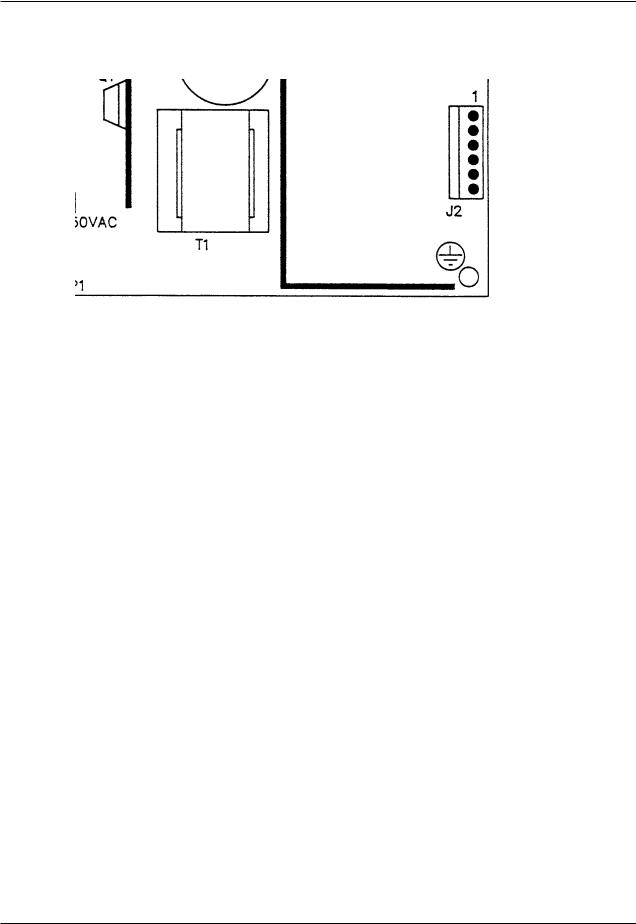
Bed Circuit Boards - Power Supply - 0059-157-000
CONNECTOR LOCATION |
VOLTAGE |
POSITIVE LEAD |
NEGATIVE LEAD |
|
|
|
|
J1 |
110V |
Pin 1 |
Pin 2 |
|
|
|
|
J2 |
12V |
Pin 1 |
Pin 4 or 5 |
|
|
|
|
J2 |
5V |
Pin 2 |
Pin 4 or 5 |
|
|
|
|
J2 |
5V |
Pin 3 |
Pin 4 or 5 |
|
|
|
|
J2 |
GND |
Pin 4 |
Pin 4 or 5 |
|
|
|
|
J2 |
GND |
Pin 5 |
Pin 4 or 5 |
|
|
|
|
J2 |
-12V |
Pin 6 |
Pin 4 or 5 |
|
|
|
|
Return To Table of Contents
26 |
4701-109-002 REV C |
www.stryker.com |

Electrical Service Information
Bed Circuit Boards - Foot Power Board - 4701-080-053
J4
J6
|
|
|
|
|
|
|
|
|
|
|
J3 |
J2 |
J5 |
|
|||
|
|
|
|
|
|
|
|
|
CONNECTOR |
CABLE |
VOLTAGE |
|
POSITIVE LEAD |
NEGATIVE |
DESCRIPTION |
||
LOCATION |
LOCATION |
|
LEAD |
|||||
|
|
|
|
|
||||
|
|
|
|
|
|
|
||
J1 |
A |
120 VAC* |
|
Pin 1 |
Pin 2 |
AC Line Voltage |
||
|
|
|
|
|
|
|
|
from CPU Board |
|
|
|
|
|
|
|
||
J4 |
G |
+5 VDC |
|
Pin 2 White |
Pin 1 Black |
+5 VDC from CPU |
||
|
|
|
|
|
|
|
||
J4 |
G |
12 VDC |
|
Pin 3 |
Pin 1 Black |
DC Voltage from CPU |
||
|
|
|
|
|
|
|
||
J4 |
G |
0 VDC W/O Switch |
|
Pin 5 Orange |
Pin 1 Black |
Foot Down |
||
|
|
5 VDC W/Switch |
|
|
|
|
|
|
|
|
|
|
|
|
|
||
J4 |
G |
0 VDC W/O Switch |
|
Pin 4 Green |
Pin 1 Black |
Foot Up |
||
|
|
5 VDC W/Switch |
|
|
|
|
|
|
|
|
|
|
|
|
|
||
J4 |
G |
0 VDC W/O Switch |
|
Pin 6 Blue |
Pin 1 Black |
Compressor |
||
|
|
5 VDC W/Switch |
|
|
|
|
|
|
|
|
|
|
|
|
|
||
J4 |
G |
0 VDC W/O Switch |
|
Pin 7 |
Pin 1 Black |
Lumbar Soft |
||
|
|
5 VDC W/Switch |
|
White/Black |
|
|
|
|
|
|
|
|
|
|
|
||
J4 |
G |
0 VDC W/O Switch |
|
Pin 8 Red/Black |
Pin 1 Black |
Lumbar Firm |
||
|
|
5 VDC W/Switch |
|
|
|
|
|
|
|
|
|
|
|
|
|
||
J4 |
G |
0 VDC W/O Switch |
|
Pin 9 |
Pin 1 Black |
Seat Soft |
||
|
|
5 VDC W/Switch |
|
Green/Black |
|
|
|
|
|
|
|
|
|
|
|
||
J3 |
E |
0 VAC W/O Switch |
|
Pin 2 |
Pin 1 |
Seat Soft |
||
|
|
120 VAC W/Switch |
|
|
|
|
|
|
|
|
|
|
|
|
|
||
J3 |
E |
0 VAC W/O Switch |
|
Pin 3 |
Pin 1 |
Seat Firm |
||
|
|
120 VAC W/Switch |
|
|
|
|
|
|
|
|
|
|
|
|
|
||
J4 |
E |
0 VDC W/O Switch |
|
Pin 10 |
Pin 1 Black |
Seat Firm |
||
|
|
5 VDC W/Switch |
|
Orange/Black |
|
|
|
|
|
|
|
|
|
|
|
||
J2 |
C |
0 VAC W/O Switch |
|
Pin 2 |
Pin 1 |
Lumbar Soft |
||
|
|
120 VAC W/Switch |
|
|
|
|
|
|
|
|
|
|
|
|
|
||
J2 |
C |
0 VAC W/O Switch |
|
Pin 3 |
Pin 1 |
Lumbar Soft |
||
|
|
120 VAC W/Switch |
|
|
|
|
|
|
|
|
|
|
|
|
|
||
J5 |
B |
0 VAC W/O Switch |
|
Pin 3 Black |
Pin 1 White |
Compressor |
||
|
|
120 VAC W/Switch |
|
|
|
|
|
|
|
|
|
|
|
|
|
||
J6 |
F |
0 VAC W/O Switch |
|
Pin 2 Red |
Pin 3 White |
Foot Down |
||
|
|
120 VAC W/Switch |
|
|
|
|
|
|
|
|
|
|
|
|
|
||
J6 |
F |
0 VAC W/O Switch |
|
Pin 1 Black |
Pin 3 White |
Foot Up |
||
|
|
120 VAC W/Switch |
|
|
|
|
|
|
|
|
|
|
|
|
|
|
|
* 120 VAC present when Fowler slide, lumbar, or seat button is pressed.
Return To Table of Contents
www.stryker.com |
4701-109-002 REV C |
27 |

Electrical Service Information
Optional Bed Communications Tester - 3002-045-700
Item |
Part No. |
Part Name |
Qty. |
A |
3002-045-805 |
BCT Unit |
1 |
B |
3001-303-825 |
37-Pin Cable |
1 |
C |
3002-045-806 |
Instructions |
1 |
D |
3000-303-087 |
9V Battery |
1 |
Return To Table of Contents
28 |
4701-109-002 REV C |
www.stryker.com |

Electrical Service Information
Head Wall Output Configuration
STRYKER PENDANT PORT
37−PIN CONNECTOR
Pin 1 |
Option 2 Common |
|
|
Pin 2 |
Read Light |
|
|
Pin 3 |
Room Light |
|
|
Pin 4 |
Speaker High |
|
|
Pin 5 |
Pot Wiper |
|
|
Pin 6 |
Radio Common |
|
|
Pin 7 |
Nurse Call Interlock |
|
|
Pin 8 |
Audio Transfer - |
|
|
Pin 9 |
Audio Transfer + |
1 |
Scan Line |
Pin 10 |
Interlock + |
2 |
Audio (-) |
Pin 11 |
Interlock - |
3 |
Nurse Call (+) |
Pin 12 |
Spare |
4 |
+5 VDC |
Pin 13 |
Options 3 Common |
5 |
Scan Line |
Pin 14 |
Pot Low Common |
6 |
Scan Line |
Pin 15 |
Pot High Common (Std.)/Audio (STV) |
7 |
Nurse Call (-) |
Pin 16 |
Nurse Answer Light + |
8 |
TV Channel Up |
Pin 17 |
Option 1 NO/NC |
9 |
Backlight |
Pin 18 |
Option 1 Common |
10 |
Audio (+) |
Pin 19 |
Nurse Call Light + |
11 |
Gatch Up/Fowler In/Foot Up/DMS Firm |
Pin 20 |
Option 2 NO/NC |
12 |
Gatch Down/Fowler Out/Foot Out/DMS Soft |
Pin 21 |
Option 3 NO/NC |
13 |
Fowler Up/Trend In |
Pin 22 |
Option 3A NO/NC |
14 |
Fowler Down/Trend Out |
Pin 23 |
Option 2A Common |
15 |
Audio Shield |
Pin 24 |
Option 2A NO/NC |
16 |
Not Used - Socket Filled |
Pin 25 |
Nurse Call + |
17 |
Bed Up |
Pin 26 |
Nurse Call NO/NC |
18 |
Ground |
Pin 27 |
Room/Read Light Common |
19 |
Read Light/Bed Down |
Pin 28 |
Nurse Call Light - |
20 |
Room Light |
Pin 29 |
Nurse Answer Light - |
|
|
Pin 30 |
Priority NO/NC |
|
|
Pin 31 |
Priority Common |
|
|
Pin 32 |
Option 3A Common |
|
|
Pin 33 |
TV - (Std.)/Data (STV) |
|
|
Pin 34 |
TV + (Std.)/Common (STV) |
|
|
Pin 35 |
Speaker Low Common |
|
|
Pin 36 |
Audio Shield |
|
|
Pin 37 |
Radio NO/NC |
|
|
Return To Table of Contents
www.stryker.com |
4701-109-002 REV C |
29 |
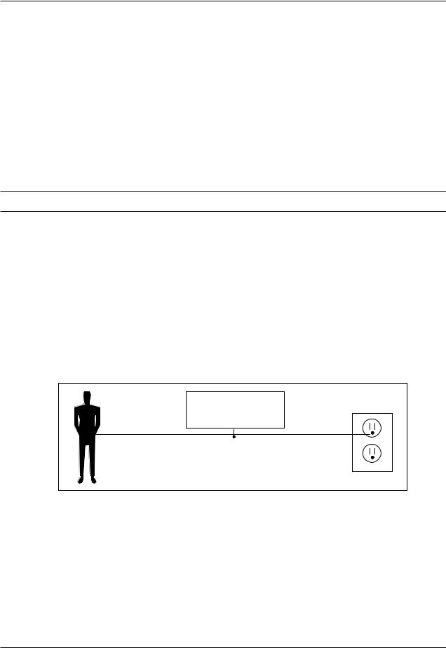
Service Information
Static Discharge Precautions
The electronic circuits in the bed are completely protected from static electricity damage only while the bed is assembled. It is extremely important that all service personnel always use adequate static protection when servicing the electronic systems of the bed. Whenever you are touching wires, you should be using static protection.
Static Protection Equipment
The necessary equipment for proper static protection is:
•1 static wrist strap; 3M part number 2214 or equivalent,
•1 grounding plug; 3M part number 61038 or equivalent,
•1 test lead with a banana plug on one end and an alligator clip on the other; Smith part number N132B699 or equivalent.
 CAUTION
All electronic service parts will be shipped in static shielding bags. Do not open the bags until you have completed steps 2 and 3 of the following procedure. Do not place unprotected circuit boards on the floor. All circuit boards to be returned to Stryker Medical should be shipped in the static shielding bags the new boards were shipped in.
Static Protection Procedure
1.Unplug the power cord from the power source.
2.Insert the grounding plug into a properly grounded hospital grade power source. Plug the banana plug of the test lead into the receptacle on the grounding plug. Connect the alligator clip on the other end of the test lead to a ground point on the bed.
3.Place the static control wrist strap on your wrist. Connect the alligator clip at the other end of the wrist strap cord to a ground point on the bed.
BED
GROUNDING DIAGRAM
Return To Table of Contents
30 |
4701-109-002 REV C |
www.stryker.com |
Loading...