


Star |
|
Installation and |
Manufacturing |
|
Operating Instructions |
International Inc. |
|
|
|
|
|
10 Sunnen Drive |
|
Instructions d’installation |
|
et d’opération |
|
St. Louis, MO 63143 |
|
|
Phone: (314) 781-2777 |
|
|
Fax: (314) 781-2714 |
|
2M-Z5486 Rev. A 7/30/06 |
|
|
|
|
|
|
ULTRA-MAX™ GAS HOTPLATE MODELS
HOTPLATE DE GAZ ULTRA-MAX™ MODELES
802H, 804H, 806H, and 808H
WARNING: Improper installation, adjustment, alteration, service or maintenance can cause property damage, injury or death. Read the installation, operating and maintenance instructions thoroughly before installing or servicing this equipment.
AVERTISSEMENT: L’installation inexacte, le réglage, le changement, le service ou l’entretien peuventcauserdesdégatsmatériels,desdommages ou la mort. Lisez les instructions d’installation, d’opération et d’entretien complètement avant d’installer ou entretenir ce matériel.
FOR YOUR SAFETY: Do not store or use gasoline or other flammable vapors or liquids in the vicinity of this or any other appliance.
POUR VOTRE SÛRETÉ: N’enregistrez pas ou n’utilisez pas l’essence ou d’autres vapeurs ou liquidesinfl ammablesàproximitédececioud’aucun autre appareil.
WARNING: This appliance shall be installed in accordance with current regulations and used only in well-ventilated space. Refer to instructions before installing and using this appliance.
AVERTISSEMENT: Cet appareil sera installé selon des règlements actuels et utilisé seulement dans l’espace bien-aéré. Référezvous aux instructions avant d’installer et utiliser cet appareil.
In addition, there should be posted, in a prominent location, detailed instructions to be followed in the event the operator smells gas. Obtain the instructions from the local gas supplier.
En outre, là devrait être signalé, dans un emplacement en avant, des instructions détaillées d’être suivi en cas que l’opérateur sent le gaz. Obtenez les instructions du fournisseur local de gaz.
SAFETY SYMBOL
These symbols are intended to alert the user to the presence of importantoperatingandmaintenanceinstructionsinthemanual accompanying the appliance.
RETAIN THIS MANUAL FOR FUTURE REFERENCE
NOTICE
Using any part other than genuine Star factory supplied parts relieves the manufacturer of all liability.
Star reserves the right to change specifi cations and product design without notice. Such revisions do not entitle the buyer to corresponding changes, improvements, additions or replacements for previously purchased equipment.
Due to periodic changes in designs, methods, procedures, policies and regulations, the specifi cations contained in this sheet are subject to change without notice. While Star Manufacturing exercises good faith efforts to provide information that is accurate, we are not responsible for errors or omissions in information provided or conclusions reached as a result of using the specifi cations. By using the information provided, the user assumes all risks in connection with such use.
MAINTENANCE AND REPAIRS
Contact your local authorized service agent for service or required maintenance. Please record the model number, serial number, voltage and purchase date in the area below and have it ready when you call to
ensure a faster service.
Model No.
Serial No.
Voltage
Purchase Date
Authorized Service Agent
Reference the listing provided with the unit or
for an updated listing go to:
Website: |
www.star-mfg.com |
Service@star-mfg.com |
|
Telephone: |
(800) 807-9054 Local (314) 781-2777 |
The Star Service Help Desk
Business |
8:00 am to 4:30 p.m. Central Standard Time |
|
Hours: |
|
|
Telephone: |
(800) 807-9054 |
Local (314) 781-2777 |
Fax: |
(800) 396-2677 |
Local (314) 781-2714 |
Parts@star-mfg.com |
||
|
Service@star-mfg.com |
|
|
Warranty@star-mfg.com |
|
Website: |
www.star-mfg.com |
|
Mailing Address: Star Manufacturing International Inc.
10 Sunnen Drive
St. Louis, MO 63143
U.S.A
2
SPECIFICATIONS:
802H
Type: Manual Control, 2-Burner
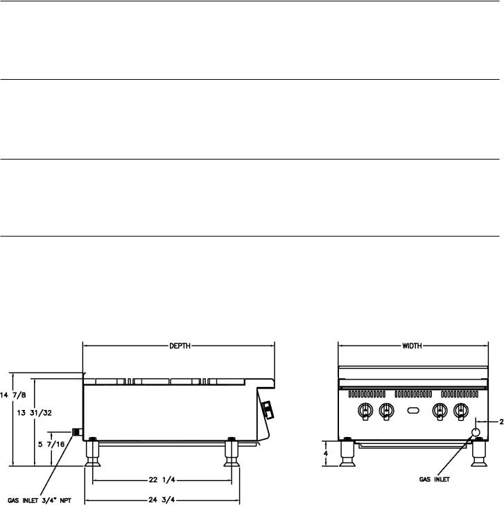
2 Controls, 60,000 BTUH Total Natural Gas (30,000 BTUH Nat/26,000 BTUH LP per burner) Approximate Weight: Installed - 70 Lb s (31.7 kg), shipping - 120 Lbs (54.4 kg) Dimensions: 12" - Width, 30 5/8" - Depth, 14 7/8" - Height
(30.5 cm - Width, 77.8 cm - Depth, 37.8 cm - Height)
804H
Type: Manual Control, 4-Burner
4 Controls, 120,000 BTUH Total Natural Gas (30,000 BTUH Nat/26,000 BTUH LP per burner) Approximate Weight: Installed - 140 Lbs (63.5 kg), shipping - 216 Lbs, (97.9 kg) Dimensions: 24" - Width, 30 5/8" - Depth, 14 7/8" - Height
(61 cm - Width, 77.8 cm - Depth, 37.8 cm - Height)
806H
Type: Manual Control, 6-Burner
6 Controls, 180,000 BTUH Total Natural Gas (30,000 BTUH Nat/26,000 BTUH LP per burner) Approximate Weight: Installed - 210 Lbs (95.2 kg), shipping - 294 Lbs, (133.3 kg) Dimensions: 36" - Width, 30 5/8" - Depth, 14 7/8" - Height
(91.4 cm - Width, 77.8 cm - Depth, 37.8 cm - Height)
808H
Type: Manual Control, 8-Burner
8 Controls, 240,000 BTUH Total Natural Gas (30,000 BTUH Nat/26,000 BTUH LP per burner) Approximate Weight: Installed - 280 Lbs (127 kg), shipping - 380 Lbs, (172.3 kg) Dimensions: 48" - Width, 30 5/8" - Depth, 14 7/8" - Height
(122 cm - Width, 77.8 cm - Depth, 37.8 cm - Height)
3

GENERAL INSTALLATION DATA
CAUTION
Thisequipmentisdesignedandsoldforcommercialuseonlybypersonneltrainedandexperienced in its operation and is not sold for consumer use in and around the home nor for use directly by the general public in food service locations.
The Ultra-Max™ series gas hotplate is equipped for the type of gas indicated on the nameplate mounted on the front panel. All units are shipped from the factory for use with natural gas. The unit can easily be converted for use with propane gas: see propane gas.
-IMPORTANT-
Be sure to remove all paper protection and packing material from unit prior to lighting.
Install on non-combustible countertop with 4" legs or combustible fl oor using a maximum 27" high stand. Clearance from combustible construction must be 9" minimum from back wall and 7" from side walls. Clearance from non-combustible surfaces on back and sides may be 0". For servicing, 6" is recommended from back of unit on non-combustible walls.
The installation of the Appliance must conform to the NATIONAL FUEL GAS CODE "ANSI Z223.1 - LATEST EDITION" AND ALL LOCAL GAS COMPANY RULES AND REGULATIONS.
IN CANADA INSTALLATION SHALL BE IN ACCORDANCE WITH THE CURRENT CAN/CGA-B149.1 NATURAL GAS INSTALLATION CODE OR CAN/CGA-B149.2 PROPANE INSTALLATION CODE AND LOCAL CODES WHERE APPLICABLE
NOTICE
When this appliance is installed with casters, it must be installed with the casters supplied, a connector complying with either ANSI Z21.69 or CAN/CGA-6.16 and a quick-disconnect device complying with either ANSI Z21.41 or CAN1-6.9. It must also be installed with
restraining means to guard against transmission of strain to the connector, as specifi ed in the appliance manufacturer's instructions.
For your protection, we recommend a qualified installing agency install this appliance. They should be familiar with gas installations and your local gas requirements. In any case, your gas company should be called to approve the final installation.
This appliance, its pressure regulator and its individual shutoff valve must be disconnected from the gas supply piping system during any pressure testing of that system at test pressures in excess of 1/2 PSIG. This appliance and its pressure regulator must be isolated from the gas supply piping system by closing its individual manual shutoff valve during any pressure testing of the gas supply piping system at test pressures equal to or less than 1/2 PSIG.
EXHAUST CANOPY
Open hotplates create fumes, moisture, heat, and should be installed under an effi cient exhaust hood with fl ame proof fi lters. A vertical distance of not less than 48" shall be provided between the top of the appliance and fi lters or any other combustible material. Exhaust installation must conform to local codes.
AIR SUPPLY
Provisions for adequate air supply must be provided.
CAUTION AIR INTAKES IN BOTTOM
Air for combustion enters from the front and bottom of the unit. Do not obstruct this area.
5

LEVELING UNIT
This hotplate is supplied with 4 feet or fl oor stand legs which must be screwed into the body. Unit must be level. Level unit by adjusting the (4) feet which have an adjustment of 1-3/4" for accurate and perfect line-up with other units.
CAUTION
DO NOT INSTALL WITHOUT ATTACHING FEET OR SUPPLIED STAND LEGS AND SHELF - DO NOT REMOVE FEET.
Caster Kits: Casters can be used with fl oor stand models or optional equipment stand. For installation, carefully mark and cut off from the bottom of each leg using a straight cutting saw and de-burr the inside tube wall prior to installing the caster. Cut leg should measure 19" tube length, not overall length. On SFC models only, use kit number ES-UM36SFC. Casters add about 6-1/4" of height to the unit. Be sure to use approved strain relief means for protecting gas line connection. If an appliance is equipped with casters and is gas connected with a quick connect coupling, all personnel must be aware that there is a restraint on the appliance and if disconnected for service or cleaning it must be reconnected as originally installed prior to use.
6
 Loading...