


XVS-7000
Table of contents
 Loading...
Sony XVS-7000, XVS-9000, XVS-6000, XVS-8000, XKS-S9112 User Manual
...
Multi Format Switcher System
XVS-9000 System
XVS-8000 System
XVS-7000 System
XVS-6000 System
(With ICP-X7000 Integrated Control Panel)
XVS-9000 XVS-8000 XVS-7000 XVS-6000
XKS-S9112 XKS-S8110 XKS-S8111 XKS-S8112
XKS-T8110 XKS-Q8111 XKS-S9167 XKS-S8165
XKS-S8167 XKS-T8165 XKS-Q8166 XKS-8160
XKS-8210 XKS-7210 XKS-8440 XKS-8460
XKS-8470 XKS-8475
XZS-9200 XZS-9510 XZS-9520 XZS-9530
XZS-9540 XZS-9550 XZS-8200 XZS-8510
XZS-8520 XZS-8530 XZS-8540 XZS-8550
XZS-7200 XZS-7510 XZS-7520 XZS-7530
XZS-6200 XZS-6510 XZS-6520
ICP-X7000 MKS-X7075 MKS-X7011 MKS-X7017
MKS-X7018 MKS-X7019 MKS-X7020 MKS-X7021
MKS-X7023 MKS-X7024 MKS-X7026 MKS-X7031TB
MKS-X7032 MKS-X7033 MKS-X7035 MKS-X7040
MKS-X7041 MKS-X7042
MKS-X2700 MKS-X7700 MKS-X7701 MKS-X7702
User’s Guide [English]
Software Version 3.0 and Later
1st Edition (Revised 7)

NOTICE TO USERS
© 2015, 2016, 2017, 2018 Sony Corporation. All
rights reserved. This manual or the software
described herein, in whole or in part, may not be
reproduced, translated or reduced to any machine
readable form without prior written approval from
Sony Corporation.
SONY CORPORATION PROVIDES NO
WARRANTY WITH REGARD TO THIS MANUAL,
THE SOFTWARE OR OTHER INFORMATION
CONTAINED HEREIN AND HEREBY EXPRESSLY
DISCLAIMS ANY IMPLIED WARRANTIES OF
MERCHANTABILITY OR FITNESS FOR ANY
PARTICULAR PURPOSE WITH REGARD TO THIS
MANUAL, THE SOFTWARE OR SUCH OTHER
INFORMATION. IN NO EVENT SHALL SONY
CORPORATION BE LIABLE FOR ANY
INCIDENTAL, CONSEQUENTIAL OR SPECIAL
DAMAGES, WHETHER BASED ON TORT,
CONTRACT, OR OTHERWISE, ARISING OUT OF
OR IN CONNECTION WITH THIS MANUAL, THE
SOFTWARE OR OTHER INFORMATION
CONTAINED HEREIN OR THE USE THEREOF.
Sony Corporation reserves the right to make any
modification to this manual or the information
contained herein at any time without notice.
The software described herein may also be governed
by the terms of a separate user license agreement.

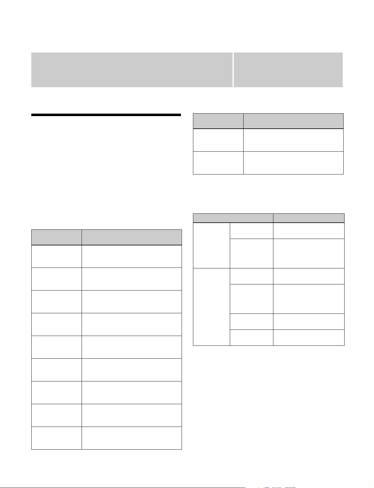
Functions Supported in Version 3.0
The functions newly supported in XVS-9000/8000/7000/
6000 System Ver. 3.0 are as follows.
Functions common to the M/E-1 to M/E-5 menus and
PGM/PST menu are indicated using M/E-1 menu
numbers. For details about the menu numbers of each
switcher bank, see “Menu Tree” (page 487).
Functions relating to the system
Classification Functions
supported
Network SMPTE ST 2110
support
Functions relating to the switcher
Menu
No.
7311.3 page 387
See page
page 434
page 443
Classification Functions
supported
DME wipe 3840×2160P 2SI
format DME wipe
support
Color corrector XKS-S8112/XKS-
S9112 color
corrector (input
signal) support
Multi viewer (XVS-9000 only)
4-system multi
viewer support
Resizer CG border settings
in 3840×2160P
format
Menu
No.
1117.3
1117.4
1117.5
1117.7
1127.3
1127.4
1127.5
1127.7
116X
7332.9 page 442
7333.1
7333.9
7333.10
1115.1 page 133
See page
page 153
page 511
page 445
page 452
Classification Functions
Input XKS-S8112/XKS-
Output XKS-S8167/XKS-
Format
converter
M/E dedicated
output
GPI output (XVS-9000 only)
DME XKS-8475 DME
supported
S9112 12G-SDI
Input Board
3840×2160P 2SI
12G format signal
input
S9167 12G-SDI
Output Board
3840×2160P 2SI
12G format signal
output
(XVS-9000 only)
Output format
converter
XKS-S8112/XKSS9112 input format
converter support
Mode settings used
for Ext Out (DME or
M/E dedicated
output)
Alarm output from
GPI connector on
switcher
Board
3840×2160P 2SI
format DME support
Menu
No.
– page 63
7332.6
7332.7
7317.3 page 63
7333.19
7333.21
7333.20
7333.21
7333.22
7332.1
7332.7
7332.8
7333.8 page 447
– page 66
– page 16
1116
1126
41XX
42XX
See page
page 434
page 66
page 440
page 398
page 443
page 66
page 447
page 450
page 444
page 450
page 434
page 439
page 209
page 120
page 126
page 209
page 511
Functions relating to setup
Classification Functions
supported
Cross-point Cross-point
switching delay
setting (cross-point
delay)
Tally Tally output prior to
cross-point
switching
(advanced tally)
Menu
No.
7322.14 page 409
7364.3 page 475
See page
Functions and Operations Not
Supported in Version 3.0
The following functions are not supported in Ver. 3.0. The
related button operation and menu settings are disabled.
For details about the timing and version for support,
contact your Sony service or sales representative.
DME channels 5 to 8
• DME channel 5 to 8 operation and settings
• DME channel 5 to 8 related bus operation and settings
• DME channel 5 to 8 region operation and settings
• 2nd DME related settings
3

Table of Contents
Functions Supported in Version 3.0..............3
Functions and Operations Not Supported in
Version 3.0...........................................3
Chapter 1 Overview
Introduction ...............................................16
Features .....................................................17
Main Functions.......................................... 18
Image Creation ............................................18
Image Data Management and Operation.....19
Setup............................................................19
Chapter 2 Menus and Control Panel
Names and Functions of Parts of the
Control Panel......................................21
Control Panel Configuration .......................21
Cross-Point Control Block .......................... 22
Transition Control Block.............................28
Transition Control Block (Simple Type) ....31
Independent Key Transition Control
Block..................................................32
Flexi Pad Control Block..............................33
Key Control Block ......................................35
Key Fader Control Block ............................38
Device Control Block (Trackball)...............39
Numeric Keypad Control Block.................. 42
Utility/Shotbox Control Block ....................44
AUX Bus Control Block ............................. 45
Menu Panel.................................................. 49
Names and Functions of Parts of the Menu
Screen .................................................51
Overview .....................................................51
Top Menu List............................................. 51
Menu Screen................................................51
Top Menu Window .....................................54
Numeric Keypad Window...........................55
Keyboard Window ......................................55
Color Palette Window .................................57
Basic Menu Operations ............................58
Recalling a Menu.........................................58
Selecting a Menu .........................................58
Selecting a List Item....................................58
Setting Parameters.......................................58
Returning Settings to Default Values..........59
Using a Mouse.............................................59
Using the Shortcut Menu.............................59
Switching between the Main Menu Site and
Sub Menu Site....................................60
Shutting Down the Menu ............................60
Shutting Down the Switcher System...........61
Power Supply and Connector Section .... 62
XVS-9000/8000/7000/6000 Multi Format
Switcher .............................................62
Control Panel...............................................68
MKS-X7011 Menu Panel............................69
MKS-X2700/X7700 System Interface
Unit ....................................................70
Chapter 3 Signal Selection and
Transitions
Image Creation Operation Flow............... 73
Signal Selection ........................................ 74
Overview .....................................................75
Bus Selection...............................................76
Signal Assignment and Selection ................78
Inhibiting Operation of Cross-point
Buttons ...............................................80
Signal Name Display...................................80
Transitions.................................................81
Overview .....................................................81
Transition Type ...........................................83
Basic Operation for Transitions .............. 83
Key Priority Settings.................................85
Setting the Key Priority (Transition
Control Block) ...................................86
Key Priority Setting Operations (Menu) .....86
Displaying the Key Output Status and
Priority ...............................................87
4

Transition Type Selection ........................88
Setting the Transition Type (Menu) ............88
Super Mix Settings...................................... 88
Preset Color Mix Settings ...........................88
Executing a Transition..............................90
Transition Indicator .....................................90
Setting the Transition Rate..........................90
Pattern Limit................................................92
Executing an Auto Transition .....................93
Executing a Transition with the Fader Lever
(Manual Transition) ...........................94
Auto/Manual Transition Combination ........ 94
Non-Sync State............................................ 94
Fader Lever Operation in Bus Fixed
Mode ..................................................95
Split Fader ................................................... 96
Transition Preview ....................................97
Independent Key Transitions...................98
Overview .....................................................98
Basic Independent Key Transition
Operations........................................ 100
Selecting Independent Key Transition
Type .................................................102
Setting the Independent Key Transition
Rate ..................................................102
Fade-to-Black .......................................... 104
AUX Mix Transitions ...............................104
Chapter 4 Keys
Mask ..........................................................118
DME Effects for Keys...............................120
Specifying the Key Output Destination.....122
Blink ..........................................................122
Video Process ............................................122
Key Modify Clear......................................122
Key Operations (Key Control Block)..... 123
Selecting the Bank and Keyer ...................123
Setting the Key Type.................................123
Selecting a Key Fill ...................................124
Selecting a Key Source..............................124
Key Adjustments (Key Control
Block) ................................................125
Chroma Key Adjustments .........................125
Key Edge Modification .............................126
DME Effects for Keys...............................126
Other Key Adjustments .............................127
Resizer .....................................................128
Two-Dimensional Transforms and Rotation
of Keys .............................................128
Rotation Settings .......................................131
Virtual Image Cancelation.........................131
Interpolation Settings ................................131
Crop/Border Settings.................................131
CG Border Settings ...................................133
Effect Settings ...........................................134
Key Snapshots ........................................136
Key Snapshot Operations (Flexi Pad
Control Block) .................................136
Key Snapshot Operations (Key Fader
Control Block) .................................137
Overview ..................................................106
Key Types .................................................106
Key Modifiers ...........................................107
Key Memory .............................................108
Key Defaults.............................................. 108
Key Setting Operations (Menu)..............109
Key Setting Menus ....................................109
Setting the Key Type.................................109
Selecting Key Fill and Key Source ...........110
Chroma Key Composition and Settings ....112
Key Adjustments (Menu) ........................113
Chroma Key Adjustments .........................113
Key Edge Modification .............................115
Chapter 5 Wipes
Overview ..................................................139
Types of Wipe Pattern...............................139
Basic Wipe Setting Operations.............. 139
Selecting a Wipe Pattern ...........................139
Pattern Mix................................................140
Setting Wipe Modifiers .............................142
Wipe Modify Clear....................................148
Basic Independent Key Transition Wipe
Setting Operations ...........................148
5

Selecting an Independent Key Transition
Wipe Pattern ....................................148
Setting Independent Key Transition Wipe
Modifiers.......................................... 148
Wipe Snapshots ......................................150
Wipe Snapshot Operations (Flexi Pad
Control Block) .................................150
Wipe Snapshot Operations (Menu) ...........151
Chapter 6 DME Wipes
Overview ..................................................153
Types of DME Wipe Patterns ...................153
DME Wipe Pattern Variation and
Modifiers.......................................... 156
DME Wipe Restrictions ............................ 157
Basic DME Wipe Setting Operations.....158
Selecting a DME Wipe Pattern .................158
Setting DME Wipe Modifiers ................... 159
DME Wipe Modify Clear.......................... 162
Basic Independent Key Transition DME
Wipe Setting Operations..................162
Selecting an Independent Key Transition
Wipe Pattern ....................................162
Setting Independent Key Transition DME
Wipe Modifiers ................................162
DME Wipe Snapshots .............................164
DME Wipe Snapshot Operations (Flexi Pad
Control Block) .................................164
DME Wipe Snapshot Operations
(Menu) .............................................164
Creating User Programmable DME
Patterns .............................................165
User Programmable DME Transition
Mode ................................................165
Chapter 7 Frame Memory
Overview ..................................................168
Frame Memory Operations.....................170
Preparations............................................... 170
Frame Memory Menu................................170
Selecting an Input Image...........................172
Selecting an FM Output ............................172
Loading Image Data ..................................173
Still Image Operations ............................174
Creating a Still Image (Freeze) .................174
Recalling Still Images ...............................174
Clip Operations ....................................... 175
Creating a Clip (Recording) ......................175
Recalling Clips ..........................................175
Playing a Clip ............................................175
Clip Transitions.......................................177
Clip Transition Settings.............................177
Editing Folders and Files .......................179
Pair File Processing ...................................179
Copying and Moving Folders/Files...........179
Creating Folders ........................................180
Deleting Folders/Files ...............................180
Renaming Folders/Files.............................180
Saving Files (Store) ...................................180
Chapter 8 Color Backgrounds, Copy
and Swap, and Other Settings
Color Backgrounds................................. 181
Basic Color Background Setting
Operations ........................................181
Copy and Swap ....................................... 183
Overview ...................................................183
Basic Copy and Swap Operations .............184
Register Groups......................................185
Copying Data Between Control
Panels................................................ 186
Misc Menu................................................186
Setting DME Override (DME Forced Select
Mode)...............................................186
Configuring Virtual Shot Box/Virtual
Menu ................................................186
Setting the Safe Title Area ........................187
Displaying a List of Transition Rates and
Changing the Settings ......................187
Setting the AUX Mix Transition Rate.......188
Aux Menu................................................. 188
6

Setting the Color Corrector for an AUX
Bus ...................................................188
Status Menu.............................................190
Router Menu ............................................191
Destination Input List Display ..................191
Switching the Source for a Destination.....191
Video Process .........................................192
Overview ...................................................192
Video Process Memory .............................192
Setting the Video Process.......................... 192
Image Effect.............................................193
Chapter 9 Special Functions
Side Flags ................................................194
Overview ...................................................194
Side Flag Settings......................................194
Wipe Action on Images with Side Flags... 195
DME Wipe Action on Images with Side
Flags.................................................196
Multi Program 2 .......................................197
Overview ...................................................197
Multi Program 2 Mode Settings (Basic
Operation) ........................................199
Multi Program 2 Mode Settings (Other
Operations).......................................200
Functions Added in Multi Program 2
Mode ................................................203
Differences Between Multi Program 2 Mode
and Standard Mode .......................... 203
Multi Program 2 Mode Restrictions..........204
M/E Configuration Switching
(M/E Split)..........................................205
M/E Split Mode Settings........................... 205
Resource Sharing ................................... 206
Overview ...................................................206
Configuring Resource Sharing ..................206
Frame Memory Operations .......................207
Chapter 10 DMEs
Overview ..................................................209
Transforms in Three-Dimensional Space
(Transforms) ....................................209
Transform Operation Modes .....................212
Graphics Display .......................................214
Three-Dimensional Parameter Display .....215
Special Effects...........................................215
Global Effects............................................221
Three-Dimensional Transform
Operations ........................................ 221
Three-Dimensional Transform Basic
Operations ........................................221
Three-Dimensional Parameter Display .....223
Three-Dimensional Parameter
Entry.................................................224
Graphics Display .......................................225
Virtual Image Cancelation.........................225
Applying Special Effects (Common
Operations) .......................................226
Applying Special Effects (Edge
Effects) .............................................. 226
Border Settings ..........................................226
CG Border Settings ...................................227
Crop Settings .............................................228
Beveled Edge Settings...............................229
Key Border Settings ..................................229
Art Edge Settings.......................................230
Flex Shadow Settings ................................232
Wipe Crop Settings ...................................235
Color Mix Settings ....................................237
Applying Special Effects (Effects on the
Overall Signal) .................................. 238
Defocus Settings........................................238
Blur Settings..............................................239
Multi Move Settings..................................239
Sepia Settings ............................................239
Mono Settings............................................239
Posterization/Solarization Settings............240
Nega Settings.............................................240
Contrast Settings........................................240
Mosaic Settings .........................................240
Sketch Settings ..........................................241
7

Metal Settings............................................ 242
Dim and Fade Settings ..............................242
Glow Settings ............................................242
Mask Settings ............................................243
Freeze Settings ..........................................244
Applying Special Effects (Nonlinear Effect
Settings) ............................................245
Wave Settings............................................ 245
Mosaic Glass Settings ...............................247
Flag Settings..............................................247
Twist Settings............................................247
Ripple Settings ..........................................247
Rings Settings............................................249
Broken Glass Settings ...............................250
Flying Bar Settings....................................250
Blind Settings ............................................250
Split Settings .............................................251
Split Slide Settings ....................................251
Mirror Settings ..........................................251
Multi Mirror Settings ................................252
Kaleidoscope Settings ...............................252
Lens Settings ............................................. 252
Circle Settings ........................................... 253
Panorama Settings .....................................253
Page Turn Settings ....................................253
Roll Settings ..............................................254
Cylinder Settings .......................................254
Sphere Settings.......................................... 254
Explosion Settings.....................................255
Swirl Settings ............................................255
Melt Settings .............................................255
Character Trail Settings............................. 256
Applying Special Effects (Lighting/
Recursive Effects)............................257
Lighting Settings ....................................... 257
Trail Settings ............................................. 258
Motion Decay Settings ..............................260
Keyframe Strobe Settings..........................261
Wind Settings ............................................262
Spotlighting Settings .................................263
Applying Special Effects (Other
Effects) ..............................................269
Background Settings .................................269
Separate Sides Settings..............................269
Invert Settings............................................269
Key Density Settings.................................269
Key Source Selection ................................269
Interpolation Settings ................................270
Corner Pinning Settings.............................271
Global Effects..........................................272
Overview ...................................................272
Combiner Settings .....................................272
Brick Settings ............................................275
Shadow Settings ........................................276
Chapter 11 External Devices
Control of External Devices ...................278
Shared Functions for External Device
Control .............................................278
Control of P-Bus Devices....................... 279
Creating and Editing the P-Bus
Timeline ...........................................279
P-Bus Trigger ............................................280
Control of GPI Devices ...........................281
Creating and Editing the GPI Timeline.....281
Control of VTRs and Disk Recorders.... 283
Controlling the Tape/Disk Transport ........283
Displaying VTR/Disk Recorder
Information ......................................285
Cueup & Play ............................................286
DDR/VTR Timeline..................................287
Disk Recorder File Operations ..................290
Chapter 12 Keyframes
Regions....................................................292
Registers.................................................. 293
Keyframes................................................ 293
Effects........................................................293
Saving and Recalling Effects ....................293
Effect Attributes ........................................294
Effect Editing ............................................294
Time Settings.............................................294
Paths ..........................................................295
8

Effect Execution........................................ 298
Master Timelines.......................................298
Sequence of Keyframe Operations............298
Displaying the Timeline Menu................300
Interpreting the Timeline Menu ................300
Timeline Menu Display Settings...............301
Recalling a Register................................302
Recalling a Register (Numeric Keypad
Control Block) .................................302
Specifying the Region and Edit
Points ................................................304
Region Selection .......................................304
Edit Point Specification.............................304
Creating and Editing Keyframes............305
Creating Keyframes...................................305
Inserting Keyframes .................................. 306
Modifying Keyframes ...............................306
Deleting Keyframes...................................307
Moving Keyframes.................................... 308
Copying Keyframes...................................308
Pause..........................................................308
Keyframe Loop (Repeated Execution of a
Specified Range)..............................308
Undoing an Edit Operation .......................310
Duration Mode Setting ..............................310
Transition Mode Settings for User
Programmable DME ........................310
Time Settings...........................................313
Setting the Keyframe Duration .................313
Setting the Effect Duration........................313
Delay Setting .............................................313
Path Settings ...........................................314
Basic Path Setting Operations ...................314
Effect Execution ......................................316
Effect Execution (Utility/Shotbox Control
Block)...............................................316
Setting the Run Mode................................316
Saving Effects ......................................... 317
Creating and Saving a Master
Timeline.............................................318
Creating and Saving a Master Timeline
(Numeric Keypad Control Block)....318
Creating and Saving a Master Timeline
(Menu) .............................................319
Recalling and Executing a Master
Timeline.............................................320
Recalling and Executing a Master Timeline
(Flexi Pad Control Block)................320
Editing Registers..................................... 321
Effect Status Display .................................321
Effect Attribute Settings............................321
Effect Register Editing ..............................322
Effect Register List View and Editing ......323
Chapter 13 Snapshots
Overview ..................................................325
Snapshot Types..........................................325
Snapshot Attributes ...................................325
Snapshot Operations (Numeric Keypad
Control Block)................................... 326
Saving and Recalling Snapshots................326
Snapshot Operations (Flexi Pad Control
Block) ................................................328
Banks and Registers ..................................328
Saving and Recalling Snapshots................329
Snapshot Operations (Menu)................. 331
Selecting a Region or Reference Region...331
Setting Snapshot Attributes.......................331
Snapshot Status Display ............................332
Setting Key Snapshot Attributes ...............332
Creating and Saving a Master Snapshot....332
Snapshot Register Editing .........................333
Snapshot Register List View and
Editing..............................................333
Operations in the Misc >Snapshot Menu on a
Switcher Bank..................................333
Chapter 14 Utility/Shotbox
Utility Overview ....................................... 335
Utility Execution ......................................335
Utility Execution (Menu Panel) ................335
Utility Execution (Utility/Shotbox Control
Block)...............................................336
9

Utility Execution (Cross-Point Control
Block)...............................................336
Shotbox Overview...................................337
Shotbox Register Creation.....................338
Shotbox Register Creation (Numeric Keypad
Control Block) .................................338
Shotbox Register Creation (Menu) ...........339
Shotbox Execution..................................340
Shotbox Execution (Numeric Keypad Control
Block)...............................................340
Shotbox Execution (Flexi Pad Control
Block)...............................................341
Shotbox Execution (Utility/Shotbox
Control Block) .................................341
Shotbox Execution (Cross-Point Control
Block)...............................................342
Shotbox Register Editing ....................... 342
Offline Editing of Macro Events ...............357
Macro Attachments.................................360
Setting and Canceling a Macro
Attachment.......................................361
Displaying the Macro Attachment
Settings.............................................363
Executing a Macro by Macro
Attachment.......................................363
Menu Macros ...........................................365
Recalling a Menu Macro Register and
Executing a Menu Macro.................365
Creating and Editing a Menu Macro .........366
Menu Macro Register Editing ...................369
Macro Timeline........................................369
Creating and Editing a Macro Timeline ....370
Chapter 16 Files
Chapter 15 Macros
Macros......................................................343
Overview ...................................................343
Macro Creation and Editing ......................344
Macro Execution .......................................345
Macro Operations (Numeric Keypad
Control Block and Utility/Shotbox
Control Block)................................... 346
Recalling a Macro Register and Executing a
Macro ...............................................346
Macro Creation and Editing ......................347
Saving a Macro..........................................350
Macro Operations (Flexi Pad Control
Block) ................................................351
Recalling a Macro Register and Executing a
Macro ...............................................351
Macro Creation and Editing ......................352
Saving a Macro..........................................353
Deleting a Macro....................................... 353
Macro Operations (Cross-Point Control
Block) ................................................354
Macro Operations (Menu).......................355
Macro Register Editing .............................355
Online Editing of Macro Events................355
Overview of File Operations...................372
Operations on Individual Files............... 373
Detailed File Information ..........................373
Region Selection........................................374
Selecting a Device for Operation ..............374
Saving Files ...............................................374
Loading Files.............................................375
Copying Files ............................................375
Renaming Files..........................................375
Deleting Files ............................................375
Batch File Operations ............................. 376
Saving Files in Batch.................................376
Loading Files in Batch ..............................376
Copying Files in Batch..............................377
Frame Memory File Operations .............378
Basic Operation .........................................378
File Operations ..........................................379
Importing and Exporting ...........................380
Directory Operations .............................. 383
Creating a Directory ..................................383
Renaming a Directory ...............................383
Protecting (Write Inhibit) a Directory .......383
Deleting a Directory ..................................383
Copying Files Between Unit IDs ............ 384
10

Copying Files Between Different Unit
IDs....................................................384
Chapter 17 System Setup
Locking Setup Menu Settings ...................396
Locking File Loading Operations..............397
Enabling/Disabling SDI Output
Connectors .......................................398
Settings Relating to the Network...........385
Setting the Group ID and Unit ID of the
Menu Panel ......................................385
Configuring the NFS Server...................... 385
Configuring a Network Interface ..............386
Settings Relating to System
Configuration.................................... 388
Selecting the Operation Mode...................388
Specifying the Switcher Controlled by the
Control Panel ...................................388
Specifying the DME Used on the
Switcher ........................................... 388
Settings Relating to Signal Formats .....389
Setting the Signal Format..........................389
Enabling Passage of 59.94 (2×) Format
Signals on an AUX Bus ...................390
Switching the Input Reference Signal .......390
Adding a Payload ID .................................390
Setting the Screen Aspect Ratio ................390
Power-On (Startup) State Selection ......391
Saving and Recalling Setup Data ..............392
Selecting the Startup State.........................392
Saving User-Defined Settings ...................392
Reset and Initialization ...........................393
Settings Relating to Installation and
Devices..............................................393
Displaying Installation Detail
Information ......................................393
Installing Software ....................................393
Configuring Settings to Use the
Software ...........................................394
Settings Relating to Device
Management .....................................396
Setting the Date and Time......................... 396
Using a Removable Drive .........................396
Setting a Removable Drive as the Primary
Device ..............................................396
Initializing the Local Drive ....................... 396
Chapter 18 Control Panel Setup
Settings Relating to Control Panel
Configuration.................................... 399
Setting the Configuration for Each
Bank .................................................399
Inhibiting Operation on a Bank .................399
Assigning a Single M/E to Two M/E
Banks................................................399
Linking Switcher Bus and Router
Destinations......................................400
Linking Transitions Between Keyers ........401
Setting the Buttons and Fader Levers on the
Key Fader Control Block .................401
Assigning a Region to the Region Selection
Buttons in the Numeric Keypad Control
Block ................................................402
Setting Transition Control Block Button
Assignments.....................................403
Setting Independent Key Transition Control
Block Button Assignments ..............403
Setting Flexi Pad Control Block Button
Assignments.....................................403
Setting Utility/Shotbox Control Block Button
Assignments.....................................403
Setting Device Control Block (Trackball)
Button Assignments.........................404
Setting Menu Panel Button
Assignments.....................................404
Inhibiting Utility 2 Bus and Key
Operations ........................................404
Inhibiting DME Channel Selection
Operations ........................................405
Inhibiting Operation on the Key Control
Block ................................................405
Cross-Point Settings............................... 405
Creating Cross-Point Assign Tables..........405
Copying Cross-Point Assign Tables..........408
Selecting Cross-Point Assign Tables ........408
11

Exporting Source Names and Destination
Names ..............................................408
Assigning the [SIDE FLAG] Button......... 408
Setting the Cross-Point Delay ................... 409
AUX Bus Control Block Settings ........... 410
Setting the AUX Bus Operation Mode .....410
Setting the Router Operation Mode ..........410
Settings Relating to Button
Assignment.......................................412
Assigning Functions to User Preference
Buttons .............................................412
Assigning a Function to a Memory Recall
Button in the Utility/Shotbox Control
Block................................................415
Assigning Functions to Cross-Point Buttons of
the Cross-Point Control Block.........418
Settings Relating to Device
Connections......................................419
Setting the Control Mode for P-Bus
Devices.............................................419
Assigning the Target Port to a Channel
Selection Button............................... 419
Setting the AUX Bus Override Operation
Mode ................................................420
Settings Relating to Operation ..............420
Setting the On-Air Tally............................ 420
Setting the Transition Rate Display
Mode ................................................420
Setting the Main Fader Lever....................420
Configuring Settings Relating to
Effects ..............................................421
Setting Source Names and Destination
Names ..............................................421
Setting Flexi Pad Control Block Button
Display and Operation .....................422
Setting the Button and Fader Lever Operation
Mode ................................................422
Setting the Operation Mode of the [ALL]
Button in the Transition Control
Block................................................423
Setting Device Control Block Button and
Trackball Operation ......................... 423
Setting the Macro Execution Mode........... 423
Setting the Operation Mode of the Cross-Point
Control Block Button Rows............. 424
Setting Button and Indicator Status on the
Cross-Point Control Block/AUX Bus
Control Block...................................425
Configuring the Cross-Point Pad...............425
Copying Cross-Point Pad Settings ............427
Setting the Display Mode of the Cross-Point
Control Block/AUX Bus Control
Block ................................................427
Setting Utility Bus Mode...........................428
Settings Relating to Control Panel
Management ..................................... 428
Setting the Screen Saver............................428
Setting Panel Sleep Mode..........................428
Adjusting the Brightness ...........................428
Setting the State of Buttons that are Not
Lit.....................................................429
Setting Beep Sound for Touch
Operation..........................................429
Calibrating the Touch Panel ......................429
Setting the Menu to Display at Startup .....429
Inhibiting Operation in the Sub Menu
Site ...................................................429
Setting the Mouse Wheel Function when
Setting Parameters ...........................429
Setting the Mouse Button Function when
Setting Parameters ...........................429
Chapter 19 Switcher Setup
Settings Relating to Switcher
Configuration.................................... 430
Adjusting the Reference Phase..................430
Specifying the Video Switching Timing ...430
Setting the Operation Mode ......................430
Setting User Regions.................................432
Assigning PGM/PST Logically to an
M/E ..................................................432
Setting DME Channel Assignments..........432
Setting the Side Flag Material and
Operation..........................................432
Setting the Sub Key Mode.........................433
Setting the Keys and DME Channels used in a
CG Border........................................433
Enabling Keyer Free Re-Entry ..................433
12

Settings Relating to Signal Inputs.........434
Setting Through Mode ..............................435
Setting the Illegal Color Limiter ...............435
Setting Dedicated Inputs ...........................435
Setting Internal Format Converter
Inputs ...............................................436
Setting an Input Format Converter............439
Setting the Input Signal Color
Corrector ..........................................442
Setting the Active Area .............................443
Settings Relating to Signal Outputs......443
Assigning Output Signals..........................445
Adjusting Video Clips...............................445
Setting the Vertical Blanking Interval and
Through Mode .................................446
Setting the Safe Title Area ........................ 446
Cropping a 4:3 Mode Image in HD
Format.............................................. 446
Setting the SDI Output Mode....................447
Setting M/E Dedicated Outputs.................447
Setting the Internal Format Converters .....448
Setting Internal Format Converter
Outputs.............................................448
Setting an Output Format Converter .........450
Setting the P/I Converter ...........................451
Configuring Multi Viewer.........................452
Enabling AUX Mix Transitions ................454
Setting the Active Area .............................454
Settings Relating to Video Switching.... 455
Enabling/Disabling the Fade-to-Black
Function ........................................... 455
Setting a Preset Color Mix ........................ 455
Setting Fader Lever Operations.................455
Setting the DME Wipe Edge Softness
Function ........................................... 455
Selecting the Bank to Configure ...............455
Settings Relating to Keys, Wipes, and
Frame Memory..................................456
Setting the Video Process Memory........... 456
Setting Show Key......................................456
Setting the Key Auto Drop Function.........456
Selecting the Bank to Configure ...............457
Settings Relating to Function Links...... 458
Setting a Cross-Point Button Link ............458
Setting a Link Table ..................................458
Setting a Link Between M/E Banks ..........458
Setting Key Transition Links ....................459
Setting a Color Corrector Link Group.......459
Settings Relating to Device
Connections...................................... 459
Assigning an AUX Bus to Ext In on a
DME.................................................459
Chapter 20 DME Setup
Settings Relating to Signal Inputs......... 460
Setting Initial Crop ....................................460
Setting the Illegal Color Limiter for Matte
Signals..............................................460
Chapter 21 DCU Setup
Parallel Input Settings ............................461
Assigning a GPI Input Port .......................461
Releasing a GPI Input Port Assignment....462
GPI Input Settings...................................462
Configuring GPI Inputs .............................462
Parallel Output Settings .........................464
Assigning a GPI Output Port.....................464
Releasing a GPI Output Port
Assignment ......................................464
GPI Output Settings................................465
Configuring GPI Outputs ..........................465
Configuring the Connection Port of
External Devices...............................466
Configuring the Connection Port ..............466
Configuring the Connected Device ...........466
Chapter 22 Router Interface and
Tally Setup
Router Interface Settings .......................471
Assigning Switcher Inputs/Outputs to
S-Bus/NS-Bus Space .......................471
13

Setting External Boxes 1 to 12..................472
Setting the Group Number of a Description
Name/Alias Name............................472
Tally Group Settings...............................473
Setting the Tally Group .............................473
Wiring Settings........................................ 473
Configuring Wiring ...................................473
Modifying Wiring Settings........................473
Deleting Wiring Settings...........................474
Sorting Wiring Settings.............................474
Tally Generation Settings....................... 474
Configuring Tally Generation ...................474
Modifying Tally Generation......................474
Deleting Tally Generation .........................475
Setting Advanced Tally............................. 475
Tally Copy Settings.................................475
Configuring Tally Copy ............................ 475
Modifying Tally Copy............................... 475
Deleting Tally Copy ..................................476
Parallel Tally Settings.............................476
Configuring/Modifying Parallel Tally ......476
Deleting Parallel Tally ..............................477
Serial Tally Settings................................477
Configuring/Modifying Serial Tally .........477
Configuring the Serial Tally Source
Address ............................................477
Clearing Source Address Settings .............478
Chapter 23 Diagnostics
Control Panel Connection Status ..........479
Appendix
Wipe Pattern List.....................................480
Wipe Pattern List....................................... 480
DME Wipe Pattern List.............................481
Resizer DME Wipe Pattern List................486
Menu Tree ................................................487
M/E-1 to M/E-5 Menus, PGM/PST
Menu ................................................487
Frame Memory Menu................................489
Color Bkgd Menu......................................490
Aux Menu..................................................490
Copy/Swap Menu......................................490
Misc Menu.................................................490
Status Menu...............................................491
DME Menu................................................491
Global Effect Menu ...................................493
Router Menu..............................................493
Device Menu .............................................493
Macro Menu ..............................................494
Key Frame Menu.......................................495
Effect Menu...............................................495
Snapshot Menu..........................................497
Shotbox Menu ...........................................498
File Menu ..................................................498
Engineering Setup Menu ...........................500
Diag Menu.................................................505
Menus Recalled by Pressing a Button
Twice ................................................. 506
XVS-9000/8000/7000/6000 System
Configuration Comparison..............509
4K Format Restrictions...........................511
Resource Sharing Configuration
Operations ........................................ 512
File Manager ............................................ 516
Preparations ...............................................516
Switcher/Panel Menu Operations..............516
Frame Memory Import Menu
Operations ........................................517
Resource Share Menu Operations .............518
Simple Connection of the MKS-8080/8082
AUX Bus Remote Panel ................... 519
Procedure for Simple Connection .............519
Setting Status of the MKS-8080/8082 in
Simple Connection...........................520
Macro File Editing Rules ........................520
Macro File Syntax .....................................520
Syntax of Event and Continue
Statements ........................................520
File Name ..................................................521
Saving and Loading a File.........................521
Errors .........................................................521
14

Correspondence Between Events and
Symbols ...........................................522
Symbols and Parameters ...........................523
Example of File Contents..........................527
Content Displayed in Macro Attachment
List .....................................................528
M/E and PGM/PST Banks ........................528
AUX Bus Control Block ........................... 529
Other Blocks.............................................. 530
Menu Operations Not Registered in a Menu
Macro.................................................531
Data Saved by [Setup Define] and [Init
Status Define] ...................................532
Data Saved by [Setup Define] ...................532
Data Saved by [Init Status Define]............533
Error Messages .......................................535
Error Messages Displayed in the Error
Status/Error Log Menu ....................535
Error Messages Appearing in a Message
Box...................................................536
Error Messages Shown in the Error
Information Menu ............................541
Maintenance ............................................542
Replacing Keytop Labels ..........................542
Cleaning the Control Panel .......................542
Index ........................................................ 543
15
Overview
Chapter
1
Introduction
This manual describes the functions and operation of the
XVS-9000/8000/7000/6000 Multi Format Switcher
system.
It describes picture creation and configuration settings
using the ICP-X7000 Integrated Control Panel.
System configuration devices
The principal components of the XVS-9000/8000/7000/
6000 system and the terms used in this manual are as
follows.
Configuration
device
XVS-9000
Multi Format
Switcher
XVS-8000
Multi Format
Switcher
XVS-7000
Multi Format
Switcher
XVS-6000
Multi Format
Switcher
ICP-X7000
Integrated Control
Panel
PWS-110SC1
Switcher Control
Station
PWS-100SC1
Switcher Control
Station
XKS-8475
DME Board
XKS-8470
HD DME Board
Terms used in this manual
• XVS-9000
•Switcher
• Multi format switcher
• XVS-8000
•Switcher
• Multi format switcher
• XVS-7000
•Switcher
• Multi format switcher
• XVS-6000
•Switcher
• Multi format switcher
• ICP-X7000
• Control panel
• Integrated control panel
• PWS-110SC1
•SCS
• Switcher control station
• PWS-100SC1
•SCS
• Switcher control station
• XKS-8475
•DME
• DME board
• XKS-8470
•DME
• DME board
Configuration
device
MKS-X7700
System Interface
Unit
MKS-X2700
System Interface
Unit
Terms used in this manual
• MKS-X7700
•SIU
• System interface unit
• MKS-X2700
•SIU
• System interface unit
Signal format notation
The signal formats in the menu and this manual are
denoted as given below.
Format terms Format name
4K format 3840×2160P • 3840×2160P/59.94
• 3840×2160P/50
3840×2160PsF • 3840×2160PsF/29.97
• 3840×2160PsF/25
• 3840×2160PsF/24
• 3840×2160PsF/23.98
HD format 1080P • 1080P/59.94
• 1080P/50
1080PsF • 1080PsF/29.97
• 1080PsF/25
• 1080PsF/24
• 1080PsF/23.98
1080i • 1080i/59.94
• 1080i/50
720P • 720P/59.94
• 720P/50
a) SMPTE ST 425-5/SMPTE ST 2082-1, Level A, 2-sample interleave
division (2SI) and square division (SQD) compliant.
b) Square division (SQD) compliant.
c) SMPTE ST 425-1, Level A compliant.
3840×2160PsF format
In this format, 3840×2160 images are subdivided into four
and are transferred as four 1080PsF format signals.
Unless stated otherwise in this document, the term “4K
format” includes the 3840×2160PsF format.
c)
a)
a)
b)
b)
b)
b)
c)
About screenshots and illustrations
The display of operation buttons and menu screens vary,
depending on the system configuration.
16

Features
The XVS-9000/8000/7000/6000 Multi Format Switcher
system is an extensible, high performance, multifunctionality switcher system that supports 4K video
creation and networked media interface (NMI) input/
output.
The following are some of the principal features of this
system.
4K format support
4K signal format is supported, enabling 4K video
processing.
The number of M/E (mix/effect) banks, keys, input/
outputs, etc. that support 4K format vary depending on the
switcher.
On the XVS-9000, up to five M/E banks are available, with
up to four keys (two keys + two sub keys)
up to 80 inputs, and up to 40 outputs (up to 48 outputs,
counting the multi viewer output connectors).
1) Sub keys are supported only when the signal format is 3840×2160P.
1)
per M/E bank,
Flexible control panel layout
Modular design enables flexible layout of the various
sections of the control panel. M/E rows can also be split
and installed on curved surfaces or in different locations.
The control panel can be configured in accordance with the
operational environment and organization of systems.
Panel design for enhanced operability
The control panel features high visibility components,
such as organic EL (OLED) displays, cross-point buttons
with color indicators, and LCD buttons (cross-point pad,
Flexi Pad control block, utility/shotbox control block).
In addition, changeable button layouts improve the
operability, making it ideal for live production
environments in which instantaneous decisions are
required.
NMI and ST2110 support
Transfer of input/output signals is supported when
connected to an IP network.
One switcher can support a combination of SDI and IP
networks (NMI or ST2110) using the existing support for
SDI input/output.
2) The XVS-9000 does not support NMI and ST2110 input/output.
2)
Flexible device configuration
The number of M/E banks and number of inputs/outputs
can be changed using combinations of option boards.
Devices can be configured to suit the system scale and
expansion.
Also, installing an optional DME board
functionality on up to four channels on the XVS-9000.
3) 3840×2160P SQD and 3840×2160PsF SQD signal formats are not
supported.
3)
enables DME
Powerful frame memory functions
Installing an optional frame memory board enables use of
20-channel frame memory outputs.
With memory that can store about 5,000 frames of HD
images and large-capacity non-volatile storage (SSD)
installed, this enables images saved in storage to be
recalled into memory at high speed.
17

Main Functions
Image Creation
Transitions
Switching from the current video feed to a new video feed
is referred to as a transition. Switching a background video
or key insertion/removal can be performed, depending on
the transition.
The method for switching video feeds (transition type) can
be set, and the transition executed using the buttons and
fader levers on the control panel.
Independent key transitions
In addition to common transitions, it is possible to
configure independent transitions on each keyer.
Executing an independent key transition in combination
with a common transition enables different transition types
to be used for the background and keys.
For details, see “Signal Selection and Transitions”
(page 73).
DME wipes
This function switches from the current video feed to a
new video feed using a DME effect. There are two types of
DME wipe: those that can be selected in a common
transition, and those that can be selected in an independent
key transition.
You can apply various modifiers to a wipe pattern, such as
setting the wipe direction and pattern position.
Resizer DME wipes
Using the resizer, you can execute DME wipes of keys.
For details, see “DME Wipes” (page 153).
Digital Multi Effects (DME)
When used with the switcher, DME allows you to add
three-dimensional effects such as image movement,
rotation, and scaling, as well as a wide variety of special
effects.
Global effects
Global effects are special effects created by combining the
pictures of successive DME channels.
For details, see “DMEs” (page 209).
Keys
Images (keys), such as titles, can be superimposed on the
background video. Key processing is performed on a
keyer.
The key source (signal used to cut out a portion of the
background image), key fill (signal to embed in the cutout
portion) and key type (key source processing method) can
be selected for a key.
Resizer
This function adds effects, such as movement, rotation,
and scaling, to the created key.
For details, see “Keys” (page 106).
Wipes
This function switches from the current video feed to a
new video feed using a wipe pattern. There are two types
of wipe: those that can be selected in a common transition,
and those that can be selected in an independent key
transition.
You can apply various modifiers to a wipe pattern, such as
setting the wipe direction and pattern position.
For details, see “Wipes” (page 139).
Frame memory
This function freezes and captures a single frame of the
input video feed as a still image for later use. You can also
specify a range in the input video to create still images to
form a frame memory clip.
For details, see “Frame Memory” (page 168).
Color backgrounds
This function is used to create color background video,
using a color signal created by a dedicated generator.
For details, see “Color Backgrounds” (page 181).
Video process
This function adjusts the luminance and hue of the input
signal.
For details, see “Video Process” (page 192).
Side flags
This function is used to attach separate video to both sides
of a video with a 4:3 aspect ratio to make a 16:9 aspect
ratio.
For details, see “Side Flags” (page 194).
18

Image Data Management and
Operation
Macro attachments
You can execute a sequence of macros when a control
panel button or fader lever is operated by assigning the
control panel button or a fader lever to a macro register.
Keyframes
This function loads the conditions of the video at a point in
time as data which can then be recalled to reproduce the
same conditions.
By arranging multiple keyframes on the time axis
(timeline) and interpolating between successive
keyframes, you can create an effect in which there is a
continuous change from each keyframe to the next
(keyframe effect). You can save the effect in memory
(effect register) and then reproduce the same effect by
recalling it from memory as required.
For details, see “Keyframes” (page 292).
Snapshots
This function saves the conditions configured for applying
an effect to an image as data in memory (snapshot register)
which can be recalled to reproduce the same conditions as
required.
For details, see “Snapshots” (page 325).
Utility
This function is used to assign a specific action or a
shortcut for a frequently used menu to a button, which can
then be recalled by pressing the button.
For details, see “Utility Overview” (page 335).
Shotbox
This function is used to save any combination of snapshots
or keyframe effects specified for a region in memory
(shotbox register) and then recall them simultaneously as
required.
For details, see “Macros” (page 343).
Copy and swap
You can copy or swap the settings between switcher banks
or between keyers.
For details, see “Copy and Swap” (page 183).
File operations
You can save register data, including setup information
and snapshot information, as a file on the local drive or
removable drive, and recall it as required.
For details, see “Files” (page 372).
External device control
You can control the operation of external devices, such as
GPI-compatible devices, P-Bus compatible devices,
VTRs, and disk recorders.
You can also control external devices by creating a
timeline and configuring operation actions at keyframes.
For details, see “External Devices” (page 278).
Multi Program 2
This function divides a single M/E switcher bank into two
(“main” and “sub”), allowing you to create images
separately on each.
You can set separate backgrounds, keys, and transitions for
the main and sub outputs.
For details, see “Multi Program 2” (page 197).
For details, see “Shotbox Overview” (page 337).
Macros
This function is used to store a sequence of control panel
operations (events) as data in memory (macro register),
which you can recall to reproduce the same sequence of
operations as required.
Menu macros
You can register menu operations as events.
Macro timeline
You can execute macros in sequence by registering macro
recall/execute actions as keyframes on the timeline.
Setup
You perform the setup operations in the Engineering Setup
menu (hereinafter called the Setup menu).
The Setup menu is separated into the following categories.
System setup (System)
For details, see “System Setup” (page 385).
Panel setup (Panel)
For details, see “Control Panel Setup” (page 399).
19

Switcher setup (Switcher)
For details, see “Switcher Setup” (page 430).
DME setup (DME)
For details, see “DME Setup” (page 460).
DCU setup (DCU)
For details, see “DCU Setup” (page 461).
Router/tally setup (Router/Tally)
For details, see “Router Interface and Tally Setup”
(page 471).
20

Menus and Control Panel
Chapter
2
Names and Functions of Parts of the Control Panel
The number of M/Es and number of DME channels
supported by the XVS-9000, XVS-8000, XVS-7000, and
XVS-6000 are different.
Some button operations and menu settings for functions
relating to M/Es and DMEs may be unavailable,
depending on the switcher.
Control Panel Configuration
The ICP-X7000 integrated control panel provides flexible
support for a combination of several modules.
The name of each control block and the supported modules
are given below.
Control block Module
Cross-point control
block
AUX bus control block
Transition control block MKS-X7020
Transition control block
(simple type)
Independent key
transition control block
Flexi Pad control block MKS-X7024
Key control block MKS-X7035
Key fader control block MKS-X7032
Device control block
(trackball)
Numeric keypad control
block
Utility/shotbox control
block
Menu panel MKS-X7011
MKS-X7017, MKS-X7018,
MKS-X7019
MKS-X7021
MKS-X7023
MKS-X7031TB
MKS-X7026
MKS-X7033
a) b)
For details, see “XVS-9000/8000/7000/6000 System
Configuration Comparison” (page 509).
a) The cross-point control block and AUX bus control block use the same
module. You can set which control block the module is used as in the
Setup menu.
b) There are three types of modules with varying numbers of cross-point
buttons: 36 buttons (MKS-X7017), 28 buttons (MKS-X7018), and 20
buttons (MKS-X7019).
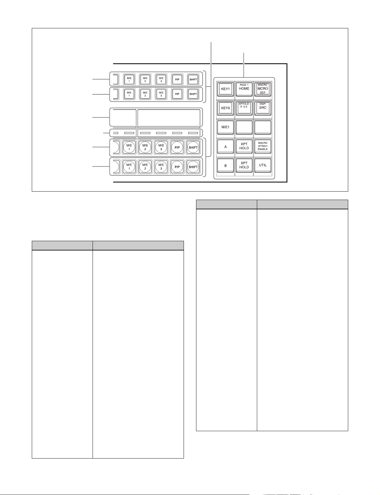
21

4M/E configuration example using 36-button modules for cross-point control block and AUX bus
control block
M/E-2 bank
M/E-1 bank
Cross-point control block (page 22)
PGM/PST (program/preset) bank
M/E-3 bank
AUX bus control block
(page 45)
Menu panel (page 49)
Key control block (page 35)
Device control block
(page 39)
Utility/shotbox control
block (page 44)
Numeric keypad control block (page 42)
Flexi Pad control block (page 33)
Transition control block (page 28)
M/E configuration example using transition control block (simple type)
Independent key transition control block (page 32)
Transition control block (simple type) (page 31) Key fader control block
Cross-Point Control Block
The cross-point control block is used to select the signals
to be used in the M/E banks and PGM/PST bank.
The button rows on the cross-point control block are set to
key bus mode by default. They can be set to free assign
mode or key/AUX bus delegation mode in the Setup menu.
For details, see “Free assign mode” (page 27) and “Key/
AUX bus delegation mode” (page 27).
Note
To use as a cross-point control block, the control panel
target row must be set to an M/E row or P/P row in the
Engineering Setup >Panel >Config menu (7321).
For details, see “Setting the Configuration for Each
Bank” (page 399).
(page 38)
22
1st row
2nd row
b Display
c Cross-point
indicators
3rd row
4th row
a Button rows
d Cross-point pad
a Button rows
Used as cross-point buttons for selecting signals and
functions.
The 1st row buttons can also be used as 2nd row delegation
buttons (key/AUX bus delegation mode).
Name Description
1st row • Selects the following bus signals
selected using the cross-point
pad delegation buttons.
Key bus
external video bus, DME utility
bus
• Selects the following functions
when utility/shotbox bank is
selected using the cross-point
pad delegation buttons (utility/
shotbox mode).
Utility command, menu shortcut,
macro recall, shotbox recall
• Selects the shifted signal on the
background A bus when the
[DUAL BKGD BUS] button of the
cross-point pad is lit (dual
background bus mode).
• Selects the DME external video
bus signal while the [UTIL] button
of the cross-point pad is pressed
(utility bus mode).
• Selects the bus signal or utility/
shotbox function
delegation button on the crosspoint pad when free assign mode
is set.
• Selects the bus or utility/shotbox
bank when key/AUX bus
delegation mode is set.
a)
, utility bus, DME
b)
c)
b)
selected by a
Name Description
2nd row • Selects the following bus signals
selected using the cross-point
pad delegation buttons.
Key bus
a)
, utility bus, DME
external video bus, DME utility
bus
• Selects the following functions
when utility/shotbox bank is
selected using the cross-point
pad delegation buttons (utility/
shotbox mode).
b)
Utility command, menu shortcut,
macro recall, shotbox recall
• Selects the shifted signal on the
background B bus when the
[DUAL BKGD BUS] button of the
cross-point pad is lit (dual
background bus mode).
• Selects the DME utility 1 bus or 2
bus signal while the [UTIL] button
of the cross-point pad is pressed
(utility bus mode).
• Selects the bus signal or utility/
shotbox function
c)
b)
selected by a
delegation button on the crosspoint pad when free assign mode
is set.
• Selects the bus signal or utility/
shotbox function
b)
selected by
the 1st row delegation button
when key/AUX bus delegation
mode is set.
23

Name Description
3rd row • Selects background A bus
signal.
• Selects the utility 1 bus signal
while the [UTIL] button of the
cross-point pad is pressed (utility
bus mode).
• Selects the bus signal or utility/
shotbox function
delegation button on the crosspoint pad when free assign mode
is set.
4th row • Selects background B bus
signal.
• Selects the utility 2 bus signal
while the [UTIL] button of the
cross-point pad is pressed (utility
bus mode).
• Selects the bus signal or utility/
shotbox function
delegation button on the crosspoint pad when free assign mode
is set.
a) When a cross-point button is pressed, a key fill signal is selected. While a
key bus delegation button is pressed, you can select a key fill signal on the
1st row and a key source signal on the 2nd row.
b) Utility/shotbox mode functions are assigned in the Setup menu. The
settings are common to the M/E and PGM/PST banks.
For details, see “Assigning Functions to Cross-Point Buttons of the CrossPoint Control Block” (page 418).
c) You can change the bus assignment and operation mode of the [UTIL]
button in the Setup menu.
For details, see “Setting Utility Bus Mode” (page 428) and “Setting the
[UTIL] button operation mode” (page 423).
c)
b)
c)
b)
selected by a
selected by a
Cross-point button numbers
The button numbers are labeled on the cross-point buttons.
For details, see “Cross-point control block button
numbers” (page 79).
Assigning signals to button numbers
You can assign a signal to each button number in the Setup
menu.
For details, see “Creating Cross-Point Assign Tables”
(page 405).
Colors of lit cross-point buttons
The status of cross-point buttons can be checked according
to the color of the button when lit.
For details about re-entry buttons, see “Re-entry buttons”
(page 75).
SHIFT button
The [SHIFT] button function is assigned to the button on
the right-hand end, and is used to toggle between the
shifted and unshifted states of the button row.
The operation of the [SHIFT] button can be set to one of
the following modes in the Setup menu.
• The shifted state is selected while the button is pressed
(hold mode).
• Every time the button is pressed, it toggles between
shifted and unshifted states (lock mode).
You can also disable the [SHIFT] button function.
For details, see “Setting the [SHIFT] button operation
mode” (page 406).
SHIFT ALL button
You can switch the cross-point button rows on all buses to
the shifted state using the [SHIFT ALL] button assigned to
the cross-point pad. The [SHIFT ALL] button operation
can be set to hold mode or lock mode in the Setup menu.
For details, see “Setting the [SHIFT ALL] button
operation mode” (page 407).
Note
The [SHIFT ALL] button is not available when a M/E or
PGM/PST bank is in the following states.
• When dual background bus mode is set
• When set to [Dual M/E Assign]
• When the operation of the [SHIFT] button of a crosspoint button row is set to hold mode
Cross-point hold function
Setting cross-point hold enables you to recall a keyframe
or snapshot while keeping the current cross-point selection
unchanged.
When cross-point hold is set, use the cross-point hold
buttons of the cross-point pad.
To set for each bus, press the cross-point hold button for
the target bus, turning the button indicator on.
To set for each cross-point button row, press the 1st row to
4th row cross-point hold buttons, turning the button
indicators on.
For details, see “Colors of lit cross-point buttons”
(page 81).
Re-entry buttons
Re-entry buttons are assigned to the cross-point button
rows (M/E-4 and M/E-5 re-entry buttons must be assigned
in the Setup menu). Re-entry buttons can also be assigned
to the cross-point pad.
You can check whether cross-point hold is set for a key bus
(K1 to K8), utility bus (U1, U2), or background bus (A, B)
on the cross-point hold status display assigned to the crosspoint pad button.
24
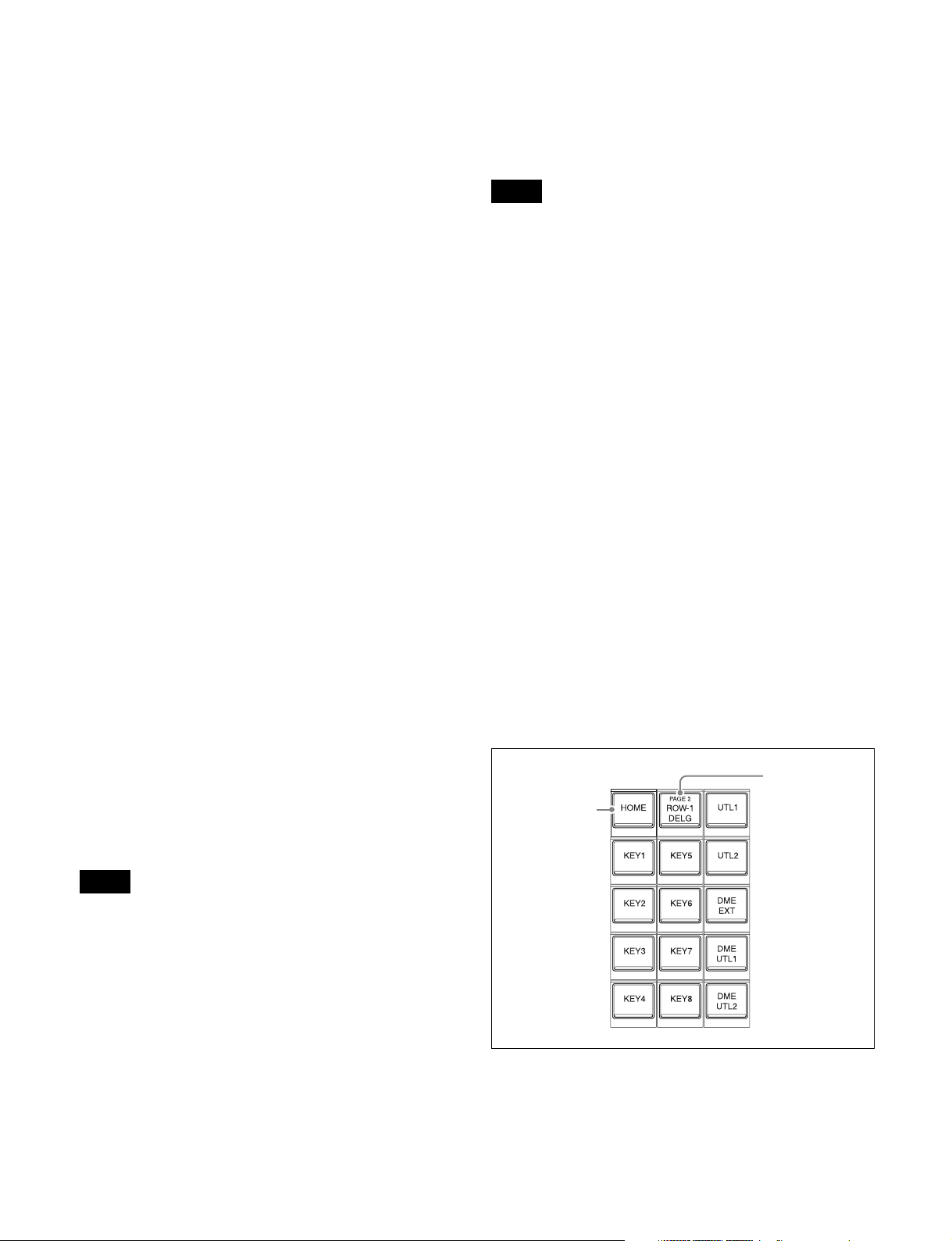
Inhibiting operation of a cross-point button row
(protect function)
To inhibit operation of buttons on the 1st to 4th rows, press
the [ROW-1 PROT] to [ROW-4 PROT] buttons on the
cross-point pad, turning them on.
• Settings of buttons on the 1st row to 4th row (signal
name, bus name, register name, or function name
assigned to the button)
• Macro register name of macro attachment assigned to
the 1st to 4th row buttons
Inhibiting operation of a cross-point button row
(inhibit function)
To inhibit operation of a cross-point button, press and hold
the [XPT INHBT SET] button on the cross-point pad, and
press the target cross-point button you want to inhibit. To
release the inhibit setting, press and hold the [XPT INHBT
SET] button on the cross-point pad, and press the target
cross-point button you want to release.
To release the inhibit setting for all buttons, press and hold
the [XPT INHBT SET] button on the cross-point pad, and
press the [XPT INHBT ALLCLR] button.
For details about the inhibit function, see “Inhibiting
Operation of Cross-point Buttons” (page 80).
KEY button
In free assign mode or key/AUX bus delegation mode, you
can select the key signal of a V/K pair using the [KEY]
button on the cross-point pad.
When a cross-point button is pressed while pressing the
[KEY] button, the key signal is selected. When a crosspoint button is pressed without pressing the [KEY] button,
the video signal is selected.
When a key source signal is selected and an operation
mode that allows you to select both a key signal and video
signal is set in the Setup menu, the [KEY] button is
enabled. In key source signal operations, when the [KEY]
button is pressed, turning it on, and a cross-point button is
pressed, the key signal is selected. When the [KEY] button
is not lit and a cross-point button is pressed, the video
signal is selected.
Information for the key signal or video signal, whichever
is selected, appears on the display.
For details, see “Setting the Button and Fader Lever
Operation Mode” (page 422).
Notes
• When the [SHIFT] button function is set, “SHFT”
appears on the display. When the shifted state is selected,
“SHFT” is highlighted in reverse video, and the button
information also toggles to show the shifted display.
• When the [SIDE FLAG] button function is set, “SIDE
FLAG” appears on the display.
The information shown in each display mode is configured
in the Setup menu. The display can also be subdivided (top
and bottom) to display two pieces of information.
For details, see “Setting the Display Mode of the CrossPoint Control Block/AUX Bus Control Block” (page 427).
c Cross-point indicators
When lit, this indicates the source color of the video signal
assigned to buttons on the 3rd row.
If a signal cannot be selected, because a signal is not
assigned or the inhibit setting is set, the indicator is not lit.
You can set whether to enable the cross-point indicator in
the Setup menu.
For details, see “Setting cross-point indicators”
(page 425).
d Cross-point pad
Contains button assignments for functions used for crosspoint operations, status display, and so on.
Current page
name indicator
HOME button
button
Note
The [KEY] button cannot be used on the following buses.
Only the video signal is selectable.
• Key fill bus
• DME video bus
• Background A bus, B bus
b Display
Six types of display mode can be selected, according to the
information to display. The display mode is switched using
the display mode buttons on the cross-point pad.
The following information can be shown on the display.
You can assign functions to each button in the Setup menu.
You can set up 14 pages of settings and assign an arbitrary
name to each M/E and PGM/PST bank.
25

For details, see “Configuring the Cross-Point Pad”
(page 425).
Use the following buttons to navigate the cross-point pad
pages.
• [HOME] button: Displays the HOME page configured
in the Setup menu.
• [<<] button: Displays the previous page (page name
below <<).
• [>>] button: Displays the next page (page name below
>>).
• Button assigned with page recall function: Displays the
page configured in the Setup menu.
If the current page name indicator button is pressed, or the
[<<] button and [>>] button are pressed simultaneously,
the cross-point pad changes to page selection display
mode, and you can press a button, turning it on, to select
the page to display. To exit page selection display, press
the [EXIT] button.
The following functions can be assigned to the cross-point
pad of the cross-point control block.
Button name
HOME Displays the HOME page of the
PREV
(<< XXX)
NEXT
(>> XXX)
Row-n Assign Status
(XXX)
Current Page Status
(PAGE 1 XXX to
PAGE14 XXX)
M/E Status
(P/P, M/E1 to M/E5)
Disp Mode Status
(DISP: XXX)
Macro Reg Status
(MACRO: XXX,
ATTCH: XXX)
PRE MACRO Sets macro attachment in pre
a)
Description
cross-point pad.
Displays the previous page of the
cross-point pad.
XXX = page name (up to 12
characters)
Displays the next page of the crosspoint pad.
XXX = page name (up to 12
characters)
Displays the bus/function names
assigned to the 1st row to 4th row.
n = 1 to 4
XXX = bus/function name
Displays the name of the currently
displayed page.
XXX = page name (up to 12
characters)
Displays the name of the currently
set bank.
Displays the name of the currently
set display mode.
XXX = display mode name (up to
12 characters)
Displays the name of the currently
recalled macro register.
Displays the macro attachment
register name while the [PRE
MACRO] button or [POST MACRO]
button is pressed.
XXX = macro register name (up to
8 characters)
macro mode.
b) c)
b) c)
c) d)
c) d)
a)
c) d)
c) d)
b) c)
b) c)
b) c)
b) c)
b) c)
Description
macro mode.
Enables macro attachments
assigned to buttons of the M/E
banks and PGM/PST bank.
Selects display mode 1 to 6 (display
mode button).
XXX = display mode name (up to
12 characters)
Assigns background A and B buses
to the 1st row to 4th row.
n = 1 to 4
Assigns key 1 to 8 buses to the 1st
row to 4th row.
n = 1 to 4
Assigns utility 1 and 2 buses to the
1st row to 4th row.
n = 1 to 4
c) d)
Assigns DME external video bus to
the 1st row to 4th row.
n = 1 to 4
c) d)
Assigns DME utility 1 and 2 buses
c) d)
to the 1st row to 4th row.
n = 1 to 4
b) c)
Assigns edit preview bus to the 1st
row to 4th row.
n = 1 to 4
Assigns AUX1 to AUX48 buses to
the 1st row to 4th row.
n = 1 to 4
Assigns frame memory source 1
and 2 buses to the 1st row to 4th
row.
n = 1 to 4
Assigns DME1 to DME4 video
buses to the 1st row to 4th row.
n = 1 to 4
Assigns DME1 to DME4 key buses
to the 1st row to 4th row.
n = 1 to 4
Assigns utility/shotbox banks 1 to
10 to the 1st row to 4th row (utility/
shotbox mode).
n = 1 to 4
Displays buses for which crosspoint hold is set.
Sets cross-point hold for the
background A or B bus.
Sets cross-point hold key 1 to 8
buses.
Sets cross-point hold for the utility 1
and 2 buses.
Button name
POST MACRO Sets macro attachment in post
MACRO ATTACH
ENABLE
DISP MODE1 to DISP
MODE6
(XXX)
ROW-n A
ROW-n B
(A, B)
ROW-n KEY1 to ROWn KEY8
(KEY1 to KEY8)
ROW-n UTIL1
ROW-n UTIL2
(UTL1, UTL2)
ROW-n DME EXT
(DME EXT)
ROW-n DME UTIL1
ROW-n DME UTIL2
(DME UTL1, DME
UTL2)
ROW-n EDIT PVW
(EDIT PVW)
ROW-n AUX1 to
ROW-n AUX48
(AUX1 to AUX48)
ROW-n FMS1
ROW-n FMS2
(FMS1, FMS2)
ROW-n DME1V to
ROW-n DME4V
(DME1V to DME4V)
ROW-n DME1K to
ROW-n DME4K
(DME1K to DME4K)
ROW-n UTIL/SBOX1
to ROW-n UTIL/
SBOX10
(UTL/SB 1 to
UTL/SB10)
Xpt Hold Status
(XPTHLD: AB U12
K1234 K5678)
XPTHLD A
XPTHLD B
XPTHLD KEY1 to
XPTHLD KEY8
XPTHLD UTIL1
XPTHLD UTIL2
(XPTHLD UTL1,
XPTHLD UTL2)
26
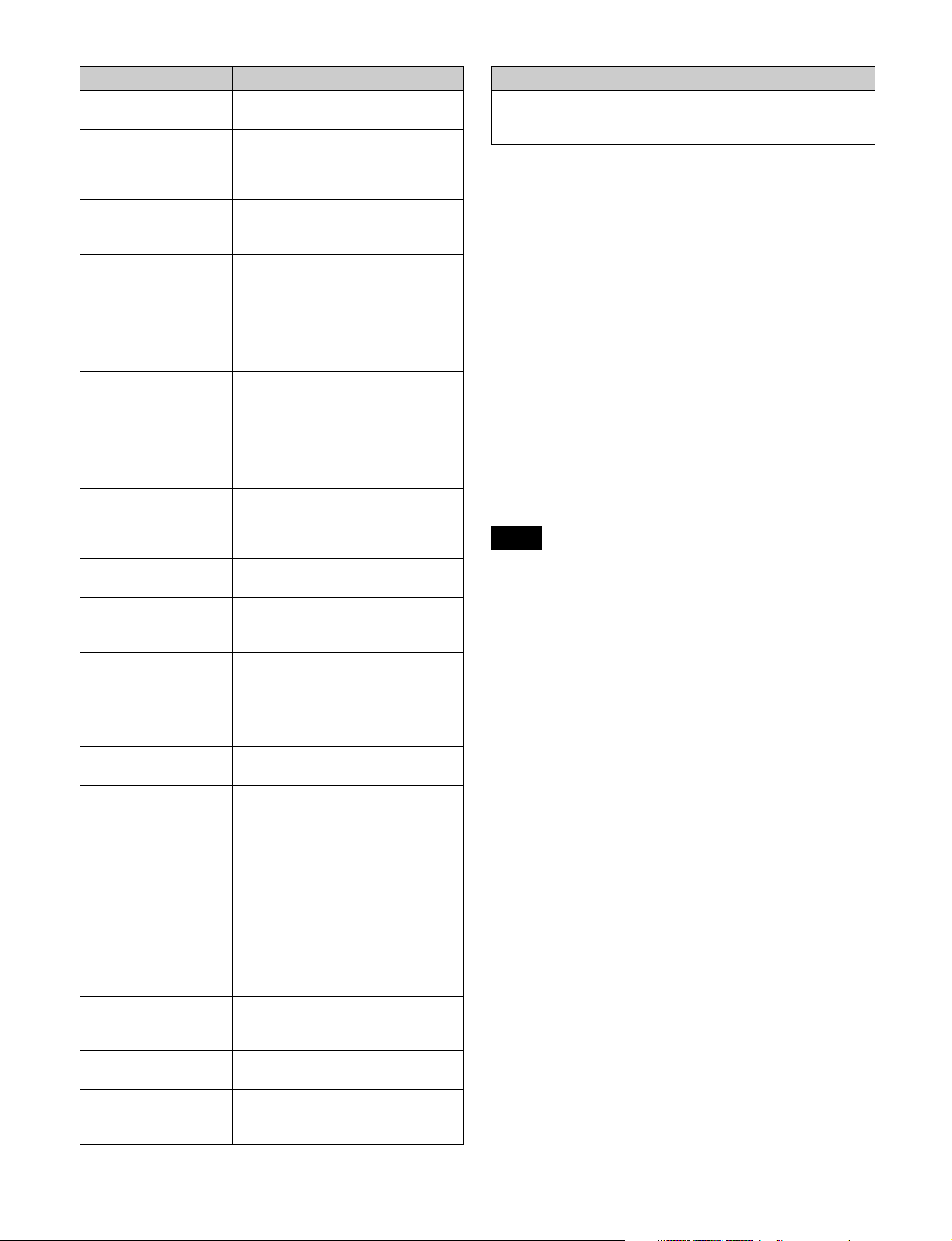
e)
b) g)
a)
b) c)
e)
f)
e)
e)
e)
b) c)
g)
Description
external video bus.
Sets cross-point hold for the DME
utility 1 and 2 buses.
Sets cross-point hold for the buses
assigned to the 1st row to 4th row.
n = 1 to 4
Loads images (OUT1) from the
PGM/PST and M/E-1 to M/E-5
e)
banks into the 1st row to 4th row
(re-entry buttons).
n = 1 to 4
XXX = Name set to P/P OUT1, M/
E-1 OUT1 to M/E-5 OUT1
Loads images (OUT6) from the
PGM/PST and M/E-1 to M/E-5
e)
banks into the 1st row to 4th row
(re-entry buttons).
n = 1 to 4
XXX = Name set to P/P OUT6, M/
E-1 OUT6 to M/E-5 OUT6
Sets the image effect on
background A bus or B bus on the
1st row to 4th row.
n = 1 to 4
Assigns the specified bus to the 1st
row to 4th row in utility bus mode.
Switches the cross-point button
rows on all buses to the shifted
state.
Executes an AUX mix transition
when an AUX bus is selected on
the 1st row to 4th row.
n = 1 to 4
Executes an AUX mix transition
when the AUX bus is selected.
Selects the signal on the key side in
the 1st row to 4th row.
n = 1 to 4
Selects the signal on the key side in
the 2nd row.
cross-point buttons.
point buttons.
Toggles dual background bus
mode.
Inhibits button operation on the 1st
row to 4th row.
n = 1 to 4
Executes a macro take operation.
Displays the macro status.
XX/XX = executed event number /
total number of events
Button name
XPTHLD DME EXT Sets cross-point hold for the DME
XPTHLD DME UTIL1
XPTHLD DME UTIL2
(XPTHLD DME UTL1,
XPTHLD DME UTL2)
ROW-n XPTHLD
(XPT HOLD)
ROW-n P/P OUT1
ROW-n M/E-1 OUT1 to
ROW-n M/E-5 OUT1
(XXX)
ROW-n P/P OUT6
ROW-n M/E-1 OUT6 to
ROW-n M/E-5 OUT6
(XXX)
ROW-n IMAGE
(IMAGE)
c) g)
UTIL
SHIFT ALL
XPTPAD COPY Copies the cross-point pad settings.
ROW-n AUX MIX
(AUX MIX)
AUX MI X
ROW-n KEY
(KEY)
b) g)
KEY
XPT INHBT SET Sets/releases inhibit mode for
XPT INHBT ALLCLR Releases inhibit mode for all cross-
DUAL BKGD BUS
ROW-n PROT
MACRO TAKE
(TAKE)
Macro Status
(EVENT XX/XX)
Button name
Macro: XXX
(XXX)
a) Button name when setting in the Setup menu. When the display differs
from that on the cross-point pad, the button name shown in parentheses
( ) is displayed.
b) Disabled in key bus mode.
c) Disabled in key/AUX bus delegation mode.
d) 3rd row and 4th row disabled in key bus mode.
e) 1st row disabled in key/AUX bus delegation mode.
f) 1st row and 2nd row disabled in key bus mode and key/AUX bus
delegation mode.
g) Disabled in free assign mode.
a)
Description
Recalls a macro register (1 to 250).
XXX = macro register name (up to
8 characters)
Free assign mode
Setting free assign mode in the Setup menu allows you to
use the 1st row to 4th row as cross-point button rows.
For details, see “Setting the Operation Mode of the CrossPoint Control Block Button Rows” (page 424).
To assign a bus/function to the 1st row to 4th row, use the
delegation buttons on the cross-point pad.
Notes
• When a key bus is assigned and a cross-point button is
pressed, a key fill signal is selected.
While a key bus delegation button is pressed, you can
select a key fill signal on the 1st row and a key source
signal on the 2nd row, regardless of the button row to
which the key bus is assigned.
• When a DME video bus or DME key bus is assigned and
a cross-point button is pressed, a front image signal is
selected. When a cross-point button is pressed while
pressing a DME video bus/DME key bus delegation
button, a rear image signal is selected.
• The operation of the [SHIFT] button is the operation
mode set by the cross-point assign table of the switcher
bank (M/E or P/P), regardless of the buses assigned to
the cross-point button rows.
Key/AUX bus delegation mode
Setting key/AUX bus delegation mode in the Setup menu
allows you to use the 1st row buttons as 2nd row
delegation buttons.
For details, see “Setting the Operation Mode of the CrossPoint Control Block Button Rows” (page 424).
27
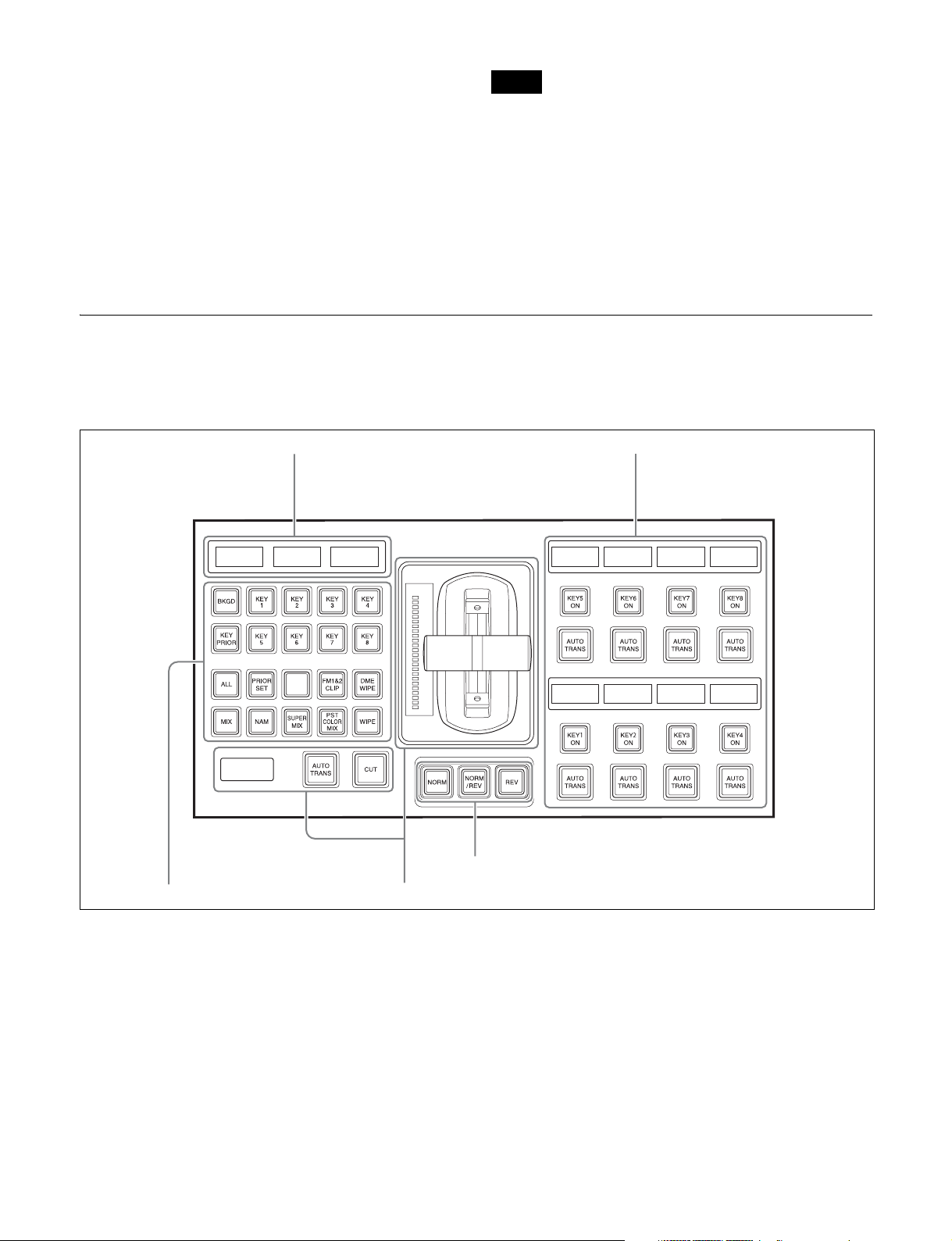
You can assign the following bus/function delegation
buttons to the 1st row.
KEY1 to KEY8
UTIL1, DME UTIL2, EDIT PVW, AUX1 to AUX48,
FMS1, FMS2, DME1 V to DME4 V
2)
K
, UTIL/SBOX1 to UTIL/SBOX10
1) When a 2nd row button is pressed, a key fill signal is selected. When a 2nd
row button is pressed while pressing a 1st row delegation button, a key
source signal is selected.
2) When a 2nd row button is pressed, a front image signal is selected. When
a 2nd row button is pressed while pressing a 1st row delegation button, a
rear image signal is selected.
1)
, UTIL1, UTIL2, DME EXT, DME
2)
, DME1 K to DME4
Transition Control Block
The transition control block is used to execute transitions.
It supports common transitions and independent key
transition.
Notes
• In key/AUX bus delegation mode, the cross-point pad
delegation buttons are not available.
• The operation of the [SHIFT] button in the 2nd row is the
operation mode set by the cross-point assign table of the
switcher bank (M/E or P/P), regardless of the bus
selected in the 1st row.
a Display
b Transition settings section
b Transition settings section cTransition execution section
d Independent key transition execution
section
a Display
The following information is displayed.
• Left-side display: Target bank name (M/E1 to M/E5, P/
P)
• Center display: State (highlighted in reverse video when
on) and priority of key 1 to key 4
• Right-side display: State (highlighted in reverse video
when on) and priority of key 5 to key 8
For details about priority of keys, see “Displaying the Key
Output Status and Priority” (page 87).
b Transition settings section
Used in the assignment of functions, such as selecting
transitions and making settings, to buttons.
You can change the assignment of buttons in the Setup
menu.
For details, see “Setting Transition Control Block Button
Assignments” (page 403).
28

Next transition selection buttons
These buttons specify how the image will be changed as a
result of the next transition.
Button name Description
BKGD (background) Press the button, turning it on, to
change the background using the
next transition.
KEY1 to KEY8 • Press the [KEY1] button, turning
it on, to insert or remove key 1
using the next transition.
If key 1 is not currently inserted, it
will be inser ted by the transition.
If key 1 is currently inserted, it will
be removed by the transition.
• The same applies to the [KEY2]
to [KEY8] buttons.
KEY1/5, KEY2/6,
KEY3/7, KEY4/8,
ADD, SHIFT
KEY PRIOR (key
priority)
ALL Selects multiple next transitions
PRIOR SET (priority
set)
(Assignment in the Setup menu is
required.)
• Press the [KEY1/5] button,
turning it on, to insert or remove
key 1 using the next transition.
Press the [SHIFT] button, turning
it on, and press the [KEY1/5]
button to insert or remove key 5.
Press and hold the [ADD] button
and press the [KEY1/5] button,
turning it on, to simultaneously
insert or remove key 1 and key 5.
• The same applies to the [KEY2/
6], [KEY3/7], and [KEY4/8]
buttons.
• Press the button, turning it on, to
enable the key priority setting
after the transition.
• When the [PRIOR SET] button is
lit, the setting for key priority after
the transition is used.
For details, see “Setting the Key
Priority (Transition Control
Block)” (page 86).
simultaneously. You set the next
transition to select in the Setup
menu.
For details, see “Setting the
Operation Mode of the [ALL] Button
in the Transition Control Block”
(page 423).
Sets the key priority.
For details, see “Setting the Key
Priority (Transition Control Block)”
(page 86).
Transition type selection buttons
These select the transition type.
• MIX button
• NAM (non-additive mix) button
• SUPER MIX button
• PST (preset) COLOR MIX button
• WIPE button
• DME WIPE button
• FM1&2 CLIP, FM3&4 CLIP, FM5&6 CLIP, FM7&8
CLIP (frame memory clip) buttons
(The [FM3&4 CLIP], [FM5&6 CLIP], and [FM7&8
CLIP] buttons must be assigned in the Setup menu.)
For details about transition types, see “Transition Type”
(page 83).
When multi-program mode is selected, there may be cases in
which two or more transition type selection buttons are lit.
For details about multi-program mode, see “Setting the
Operation Mode” (page 430).
Wipe direction selection buttons
These buttons select the wipe direction when the transition
type is a wipe or DME wipe.
Button name Description
NORM (normal) The wipe proceeds in the direction
REV (reverse) The wipe proceeds in the opposite
NORM/REV (normal/
reverse)
from black to white of the pattern
images, shown in “Wipe Pattern
List” (page 480), or in the direction
of the arrows.
direction of [NORM].
The wipe direction alternates
between normal and reverse every
time a transition is executed.
TRANS PVW (transition preview) button
(Assignment in the Setup menu is required.)
With the preview output of the M/E banks and PGM/PST
bank, you can check the effect of the image during a
transition in advance.
During preview, you can use the fader lever, [AUTO
TRANS] button, and [CUT] button.
The operation of the [TRANS PVW] button can be set to
one of the following modes in the Setup menu.
• Press the button to start transition preview mode; the
mode returns to normal mode when the transition finishes.
• The transition preview mode is maintained only while
this button is pressed.
• Each time the button is pressed, the mode toggles
between transition preview mode and normal mode.
For details, see “Setting the Button and Fader Lever
Operation Mode” (page 422) and “Setting the transition
preview mode” (page 456).
KF (keyframe) button
(Assignment in the Setup menu is required.)
You can use the fader lever as a keyframe fader.
For details about the keyframe fader, see “Effect
Execution” (page 316).
29

Pattern limit setting buttons
(Assignment in the Setup menu is required.)
These buttons are used to set pattern limits.
• PTN (pattern) LIMIT button
• LIMIT SET button
Name Description
CUT button Executes an immediate transition.
d Independent key transition execution section
This section executes independent key transitions.
For details about pattern limits, see “Pattern Limit”
(page 92).
External device operation buttons
(Assignment in the Setup menu is required.)
These buttons are used to control playback, stop, and cueup operations on connected devices.
• PLAY button
• STOP button
•CUE button
For details about operation of external devices, see
“Control of VTRs and Disk Recorders” (page 283).
c Transition execution section
This section is used to execute transitions and check the
progress of the transition.
Transition
indicator
Fader lever
Transition rate display
CUT button
AUTO TRANS button
Name Description
Fader lever • Move this up or down to carry out
the transition.
• Press the [KF] button, turning it
on, to enable the fader lever to be
used as a keyframe fader.
Transition indicator Displays the transition progress
Transition rate display Displays the configured transition
AUTO TRANS (auto
transition) button
using LEDs.
rate (the time from the beginning of
a transition to its completion).
• Executes an auto transition with
the set transition rate and
transition type.
• During the transition, the button
is lit amber.
Independent key transition display section
KEY5 ON to KEY8 ON buttons
KEY1 ON to KEY4 ON buttons
AUTO TRANS buttons
Name Description
Independent key
transition display
section
KEY1 ON to KEY8 ON
buttons
AUTO TRANS (auto
transition) buttons
Displays the following information
for key 1 to key 8.
Key material name (key source
name when a key source is
selected on the key bus of the
cross-point control block), DME
channel or resizer being used,
transition rate, and transition type
• Inserts or removes the key
instantaneously.
• If a key is currently inserted, the
corresponding key button is lit
amber.
• Inserts or removes the key
automatically, for key 1 to key8,
with the set transition rate and
transition type.
• During the transition, the button is
lit amber.
You can change the position of the key 1 to key 8 operation
buttons in the Setup menu. However, the [AUTO TRANS]
button is assigned with the [KEYx ON] (x = 1 to 8) button
of the same key as a set.
For details, see “Setting Transition Control Block Button
Assignments” (page 403).
30
Loading...