

Sony XR-C550W User Manual
Installing the rotary remote
Notes
• Choose the mounting location carefully so that the rotary
remote will not interfere with operating the car.
• Do not install the rotary remote in a place where it may
jeopardize the safety of the (front) passenger in anyway.
• When installing the rotary remote, be sure not to damage the
electrical cables etc. on the other side of the mounting surface.
• Avoid installing the rotary remote where it may be subject to
high temperatures, such as from direct sunlight or hot air from
the heater etc.
Instalación del mando rotativo
Notas
• Elija cuidadosamente el lugar de montaje de forma que el
mando rotativo no dificulte la conducción del coche.
• No instale el mando rotativo en un lugar donde pueda poner
en peligro la seguridad del pasajero acompañante.
• Al instalar el mando rotativo, asegúrese de no dañar los cables
de electricidad, etc., del otro lado de la superficie de montaje.
• Procure no instalar el mando rotativo en un lugar expuesto a
altas temperaturas, como a la luz solar directa o al aire caliente
de la calefacción, etc.
FM/MW/SW
#####
#
• ###
• ########
• #########
###
• ########
####
1
2
3
4
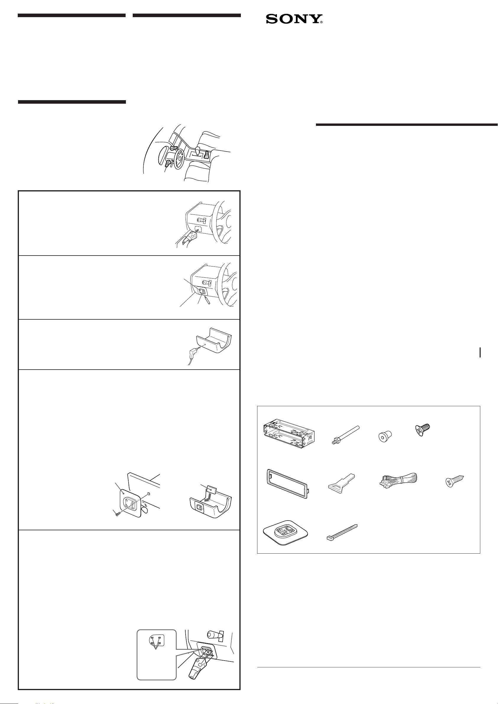
Example of a mounting location
Ejemplo de un lugar de montaje
##
Choose the exact location for mounting the rotary remote, then clean
the mounting surface.
Dirt or oil impair the adhesive strength of the double-sided adhesive tape.
Una vez elegido el lugar de montaje del mando rotativo, limpie
previamente la superficie de montaje.
La suciedad o la grasa dañan la intensidad adhesiva de la cinta adhesiva de dos caras.
#######
###########
Mark position for the supplied screw.
Use the screw hole on the mounting hardware !¡ to mark the position.
Marque la posición para los tornillos suministrados.
Para ello, utilice los orificios para tornillos de la ferretería de montaje !¡.
#######
###########
Remove the steering wheel column cover, and drill 2 mm diameter hole
at the marked position.
Extraiga la cubierta de la columna de la dirección y haga orificio de 2 mm.
de diámetro en el lugar marcado.
########
###
Warm the mounting surface and the double-sided adhesive tape on the mounting hardware
!¡ to the temperature of 20°C to 30°C, and attach the mounting hardware to the mounting
surface applying even pressure. Then screw it down with the supplied screw !º.
Attach a piece of heavy duty tape etc. on the other side of the mounting surface to cover the protruding tips of the screw
so they will not interfere with any electrical cables etc. inside the steering wheel column.
Caliente la superficie de montaje y la cinta adhesiva de doble cara de la ferretería de montaje
!¡ a una temperatura entre 20°C y 30°C, y ajuste la ferretería de montaje a la superficie de
montaje ejerciendo una presión uniforme. A continuación, apriete los tornillos !º
suministrados.
Adhiera un trozo de cinta adhesiva resistente, etc. en el otro lado de la superficie de montaje para cubrir los extremos de
los tornillos que sobresalgan, de forma que no interfieran con los cables de electricidad, etc., del interior de la columna
de dirección.
############
############
##########
!¡
Mark
Marca
##
Cassette Car
Stereo
Installation/Connections
Instalación/Conexiones
###
XR-C550W
XR-C550
Sony Corporation 1997 Printed in Japan
Parts for installation and connections
Componentes de montaje y conexiones
###
The numbers in the list are keyed to those in the instructions.
Los números de la lista corresponden a los de las instrucciones.
###
1
TOP
23
× 1
× 1 × 1
4
× 5
(incl. 1 reserve)
(se incluyen 1 de reserva)
###
Cut the mounting hardware !º, if necessary.
Si es necesario, corte la pieza !º.
######
After installing the steering wheel column cover, attach the rotary remote to the mounting
hardware by aligning the four holes on the bottom of the rotary remote with the four
5
catches on the mounting hardware and sliding the rotary remote until it locks into place as
illustrated.
Note
If you are mounting the rotary remote on the steering wheel column, make sure that the protruding tips of the screw
on the inner surface of the column do not in any way hinder or interfere with the movement of the rotating shaft,
operative parts of the switches or the electrical cables etc. inside the column.
Una vez instalada la cubierta de la columna de dirección, fije el mando rotativo a la ferretería
de montaje alineando los cuatro orificios de la parte inferior del mando con los cuatro
enganches de la ferretería de montaje. A continuación, deslice el mando hasta que encaje en
su sitio como se muestra en la ilustración.
Nota
Si monta el mando rotativo en la columna de dirección, asegúrese de que los extremos de los tornillos que sobresalgan de
la superficie interior de la columna no dificulten el movimiento del eje de rotación ni los componentes operativos de los
conmutadores o los cables de electricidad, etc., del interior de la columna.
########################
###############
####
######################
###########
!¡
!º
Holes
Orificios
##
Heavy duty tape etc.
Cinta adhesiva resistente, etc.
#####
5
9
The release key 6 is used for dismounting the unit. See the Operating Instructions manual for details.
La llave de liberación 6 se utiliza para desmontar la unidad. Con respecto a los detalles, consulte el
manual de instrucciones.
###
× 1
× 1
6
!º
78
× 1
× 1
× 1
× 1
*I-3-859-458-11*(1)
Installation
Instalación
###
Precautions
• Do not tamper with the four holes on the upper surface of the unit.
They are used for tuner adjustments to be made only by service
technicians.
• If you mount other Sony equipment with this unit, it is better to
mount this unit in the lower position.
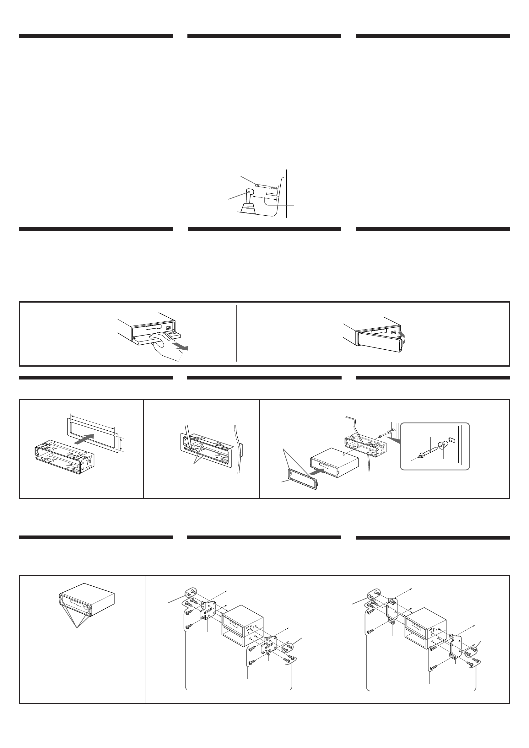
• There must be a distance of at least 15 cm between the cassettes
slot of the unit and shift lever to insert cassette easily. Choose the
installation location carefully so the unit does not interfere with
gear shifting and other driving operations.
• Choose the mounting location carefully so the unit does not
interfere with normal driving operations.
• Avoid installing the unit where it would be subject to high
temperatures, such as from direct sunlight or hot air from the
heater, or where it would be subject to dust, dirt or excessive
vibration.
• Use only the supplied mounting hardware for safe and secure
installation.
Mounting angle adjustment
Adjust the mounting angle to less than 20°.
Precauciones
• No toque los cuatro orificios de la superficie superior de la unidad.
Estos orificios son para ajustes del sintonizador que solamente
deberán realizar técnicos de reparación.
• Si monta otro equipo Sony con esta unidad, es preferible montar
esta unidad en la posición más baja.
• Para que sea posible insertar y la cinta con facilidad, debe haber
una distancia de al menos 15 cm entre la ranura de inserción de
cintas de la unidad y la palanca de cambios.
Instale la unidad en un lugar que no entorpezca las operaciones de
cambio de marchas o de conducción en general.
• Elija cuidadosamente el lugar de montaje de forma que la unidad
no interfiera las funciones normales de conducción.
• Evite instalar la unidad donde pueda quedar sometida a altas
temperaturas, como a la luz solar directa o al aire de calefacción, o
a polvo, suciedad, o vibraciones excesivas.
• Para realizar una instalación segura y firme, utilice solamente la
ferretería de montaje suministrada.
Ajuste del ángulo de montaje
Ajuste el ángulo de montaje a menos de 20°.
Cassette
Cassette
###
Shift lever
Palanca de cambios
###
more than 15 cm
más de 15 cm
###
###
• ###
• ###
• ###
• ###
• ###
###
###
How to detach and attach the front panel
Before installing the unit, detach the front panel.
To detach
Before detaching the front panel, be sure to press (OFF) first. Press
(OPEN) to open up the front panel, then pull it off towards you.
To attach
Align the front panel to the unit , and push in.
To detach
para extraerlo
###
Mounting example
Installation in the dashboard
12
182 mm
Forma de extraer e instalar el panel frontal
Antes de instalar la unidad, extraiga el panel frontal.
Para extraerlo
Antes de extraer el panel frontal, asegúrese de presionar (OFF) en
primer lugar. Presione (OPEN) para abrir el panel frontal y, a
continuación, tire de él hacia fuera.
Para instalarlo
Alinee el panel frontal con la unidad e introdúzcalo.
To attach
para instalarlo
###
Ejemplo de montaje
Instalación en el salpicadero
3
Dashboard
Salpicadero
###
###
###
###
#####
#####
###
####
###
###
Fire wall
Panel cortafuegos
###
TOP
1
With the TOP marking up
Con la marca TOP hacia arriba.
###
Caution
Cautionary notice for handling the bracket 1.
Handle the bracket carefully to avoid injuring your fingers.
Mounting the unit in a japanese car
You may not be able to install this unit in some makes of Japanese
cars. In such a case, consult your Sony dealer.
12
53 mm
Bend these claws, if necessary.
Si es necesario, doble estas uñas.
###
Precaución
Advertencia sobre la manipulación del soporte 1.
Tenga mucho cuidado al manipular el soporte para evitar posibles
lesiones en los dedos.
Montaje de la unidad en un automóvil
japonés
Usted no podrá instalar esta unidad en algunos sutomóviles
japoneses. En tal caso, consulte a su proveedor Sony.
TOYOTA
to dashboard/center console
al salpicadero/consola central
###
4
max. size
5 × 8 mm
Tamaño máx.
Claws
Pestañas
###
Cut all the claws from the unit with
pincers or other suitable tool.
Corte todas las pestañas de la unidad
con unos alicates o con otra herramienta
adecuada.
###
###
5 × 8 mm
###
###
Bracket
Soporte
###
Existing parts supplied to your car
Piezas existentes suministradas con su automóvil
###
With the TOP marking up
Con la marca TOP hacia arriba.
###
5
4
max. size
5 × 8 mm
Tamaño
máx. 5 × 8
mm
###
###
Bracket
Soporte
###
#####
##### 1.
#############
##################.
###
###
NISSAN
4
max. size
5 × 8 mm
Tamaño
máx. 5 × 8 mm
###
###
TOP
2
1
3
First attach 5 to the unit, then insert the unit into 1.
En primer lugar, fije 5 a la unidad y, a continuación, inserte ésta en 1.
###
to dashboard/center console
al salpicadero/consola central
###
4
max. size
5 × 8 mm
Tamaño
máx. 5 × 8
Bracket
Soporte
###
Bracket
Soporte
###
Existing parts supplied to your car
Piezas existentes suministradas con su automóvil
###
mm
###
###
Notes
• To prevent malfunction, install only with the supplied screws 4 and use existing
parts supplied to your car.
• If you cannot mount the unit in the lower tier after cutting off all claws, install it in
the upper tier.
Notas
• Para evitar que se produzcan fallos, realice la instalación solamente con los tornillos
suministrados 4 y utilice los componentes suministrados para el automóvil.
• Si no puede montar la unidad en la grada inferior después de haber cortado todas las
pestañas, instálela en la grada superior.
###
• ###
• ###
 Loading...