

Sony STR-DN860, STR-DN1060 Service manual
SERVICE MANUAL
Sony Corporation
Published by Sony EMCS (Malaysia) PG Tec
STR-DN860/DN1060
MULTI CHANNEL AV RECEIVER
9-890-661-01
2015B80-1
©
2015.02
Ver. 1.0 2015.02
US Model
Canadian Model
AEP Model
UK Model
Australian Model
Taiwan Model
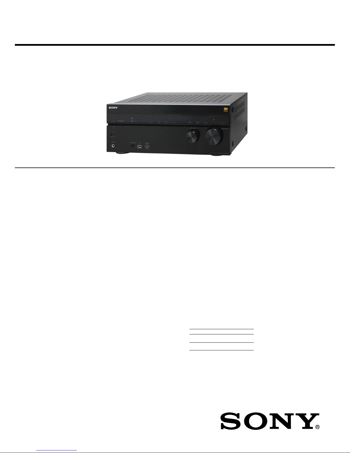
STR-DN860
– Continued on next page –
Photo: STR-DN1060
This receiver incorporates Dolby* Digital and Pro
Logic Surround and the DTS** Digital Surround
System.
* Manufactured under license from Dolby Labo-
ratories. Dolby, Pro Logic, Surround EX, and
the double-D symbol are trademarks of Dolby
Laboratories.
** For DTS patents, see http://patents.dts.com.
Manufactured under license from DTS
Licensing Limited. DTS, DTS-HD, the
Symbol, & DTS and the Symbol together are
registered trademarks, and DTS-HD Master
Audio is a trademark of DTS, Inc. © DTS, Inc.
All Rights Reserved.
This receiver incorporates High-Definition
Multimedia Interface (HDMI™) technology.
The terms HDMI and HDMI High-Definition
Multimedia Interface, and the HDMI Logo are
trademarks or registered trademarks of HDMI
Licensing LLC in the United States and other
countries.
Apple, the Apple logo, AirPlay, iPad, iPhone,
iPod, iPod classic, iPod nano, iPod touch,
and Retina are trademarks of Apple Inc.,
registered in the U.S. and other countries.
iPad Air and iPad mini are trademarks of Apple Inc.
App Store is a service mark of Apple Inc.
All other trademarks and registered trademarks
are of their respective holders. In this manual, ™
and ® marks are not specified.
“Made for iPod,” “Made for iPhone,” and “Made
for iPad” mean that an electronic accessory has been
designed to connect specifically to iPod, iPhone,
or iPad, respectively, and has been certified by the
developer to meet Apple performance standards.
Apple is not responsible for the operation of
this device or its compliance with safety and
regulatory standards. Please note that the use of
this accessory with iPod, iPhone, or iPad may
affect wireless performance.
Windows Media is either a registered trademark or
trademark of Microsoft Corporation in the United
States and/or other countries.
This product is protected by certain intellectual
property rights of Microsoft Corporation. Use
or distribution of such technology outside of
this product is prohibited without a license from
Microsoft or an authorized Microsoft subsidiary.
The LDAC™ name and logo is a trademark of
Sony Corporation.
“DSEE HX” is a trademark of Sony Corporation.
MPEG Layer-3 audio coding technology and
patents licensed from Fraunhofer IIS and
Thomson.
“x.v.Color (x.v.Colour)” and “x.v.Color
(x.v.Colour)” logo are trademarks of Sony
Corporation.
“BRAVIA” is a trademark of Sony Corporation.
“PlayStation” is a registered trademark of Sony
Computer Entertainment Inc.
“WALKMAN” and “WALKMAN” logo are
registered trademarks of Sony Corporation.
MICROVAULT is a trademark of Sony Corporation.
WPA™ and WPA2™ are trademarks of Wi-Fi
Alliance
®
.
The Wi-Fi CERTIFIED™ Logo is a certification
mark of Wi-Fi Alliance
®
.
MHL, Mobile High-Definition Link and the
MHL Logo are trademarks or registered trademarks of MHL Licensing, LLC.
The BLUETOOTH® word mark and logos
are registered trademarks owned by Bluetooth
SIG, Inc. and any use of such marks by Sony
Corporation is under license. Other trademarks
and trade names are those of their respective
owners.
The N Mark is a trademark or registered
trademark of NFC Forum, Inc. in the United
States and in other countries.
Android™ is a trademark of Google Inc.
Google Play™ is a trademark of Google Inc.
Notice on End User License
Agreement (EULA)
For details of the EULA for this product, see
page 14.
For details of the EULA for network services,
please refer to [License agreement] in options
menu on each network service icon.
For details of the GPL, LGPL and other software
licenses, please refer to [Software License
Information] in [System Settings] of the [Setup]
menu on this product.
This product contains software that is subject
to the GNU General Public License (“GPL”) or
GNU Lesser General Public License (“LGPL”).
These establish that customers have the right to
acquire, modify, and redistribute the source code
of said software in accordance with the terms of
the GPL or the LGPL.
The source code for the software used in this
product is subject to the GPL and LGPL, and is
available on the Web.
To download, please access the following:
URL:
http://oss.sony.net/Products/Linux
Please note that Sony cannot answer or respond to
any inquiries regarding the content of this source
code.
End User License Information
REAL END USER LICENSE
AGREEMENT (Taiwan models only)
1. End users are prohibited from modifying,
translating, reverse engineering, decompiling,
disassembling or using other means to discover
the software developed by Real or otherwise
replicate the functionality of the software,
except to the extent that this restriction is
expressly prohibited by applicable law.
2. Real disclaims all warranties and conditions,
express and implied, including implied
warranties or conditions of merchantability
and fitness for a particular purpose; and
effectively exclude all liability for indirect,
special, incidental and consequential damages,
including but not limited to lost profits or
replacement systems.
SPECIFICATIONS
AUDIO POWER SPECIFICATIONS
POWER OUTPUT AND TOTAL
HARMONIC DISTORTION:
(US models only)
STR-DN1060:
With 6 ohm loads, both channels driven, from
20 Hz – 20,000 Hz; rated 100 watts per channel
minimum RMS power, with no more than
0.09% total harmonic distortion from 250 milliwatts to rated output.
STR-DN860:
With 6 ohm loads, both channels driven, from
20 Hz – 20,000 Hz; rated 95 watts per channel
minimum RMS power, with no more than
0.09% total harmonic distortion from 250 milliwatts to rated output.
Amplifier section
STR-DN1060
US, Canadian, Australian and Taiwan models
1)
:
Minimum RMS Output Power
(6 ohms, 20 Hz – 20 kHz, THD 0.09%)
100 W + 100 W
Stereo Mode Output Power
(6 ohms, 1 kHz, THD 1%)
120 W + 120 W
Surround Mode Output Power
2)
(6 ohms, 1 kHz, THD 0.9%)
165 W per channel
STR-DN860
Minimum RMS Output Power
1)
(6 ohms, 20 Hz – 20 kHz, THD 0.09%)
95 W + 95 W
Stereo Mode Output Power
1)
(6 ohms, 1 kHz, THD 1%)
110 W + 110 W
Surround Mode Output Power
1)2)
(6 ohms, 1 kHz, THD 0.9%)
150 W per channel
1)
Measured under the following conditions:
Area Power requirements
US, Canadian,
Taiwan
120 V AC, 60 Hz
Australian, AEP,
UK
230 V AC, 50 Hz
2)
Reference power output for front, center,
surround, surround back and front high
speakers. Depending on the sound field settings and the source, there may be no sound
output.
Frequency response
Analog
10 Hz – 100 kHz, +0.5/–2 dB (with
sound field and equalizer bypassed)
Input
Analog
Sensitivity: 500 mV/50 kilohms
S/N3): 105 dB (A, 500 mV4))
Digital (Coaxial)
Impedance: 75 ohms
S/N: 100 dB (A, 20 kHz LPF)
Digital (Optical)
S/N: 100 dB (A, 20 kHz LPF)
Output (Analog)
ZONE 2
5)
Voltage: 2 V/1 kilohm
SUBWOOFER
Voltage: 2 V/1 kilohm
Equalizer
Gain levels
±10 dB, 1 dB step
3)
INPUT SHORT (with sound field and equalizer
bypassed).
4)
Weighted network, input level.
5)
STR-DN1060 only.
FM tuner section
Tuning range
US and Canadian models:
87.5 MHz – 108.0 MHz (100 kHz step)
Other models:
87.5 MHz – 108.0 MHz (50 kHz step)
Antenna (aerial)
FM wire antenna (aerial)
Antenna (aerial) terminals
75 ohms, unbalanced
Video section
Inputs/Outputs
Video:
1 Vp-p, 75 ohms
COMPONENT VIDEO*:
Y: 1 Vp-p, 75 ohms
P
B: 0.7 Vp-p, 75 ohms
PR: 0.7 Vp-p, 75 ohms
80 MHz HD Standby Through
* STR-DN1060 only.
STR-DN860/DN1060
2
HDMI Video
Input/Output (HDMI Repeater block)
STR-DN1060: HDMI IN SAT/CATV (MHL) and HDMI OUT A (TV) jacks support HDCP 2.2 protocol.
STR-DN860: HDMI IN SAT/CATV (MHL) and HDMI TV OUT jacks support HDCP 2.2 protocol.
HDCP 2.2 is newly enhanced copyright protection technology that is used to protect content such as 4K movies.
Format 2D
3D
Frame
packing
Side-by-Side
(Half)
Over-Under
(Top-and-Bottom)
4096 × 2160p @ 59.94/60 Hz
a
1)
–– –
4096 × 2160p @ 50 Hz
a
1)
–– –
3840 × 2160p @ 59.94/60 Hz
a
1)
–– –
3840 × 2160p @ 50 Hz
a
1)
–– –
4096 × 2160p @ 23.98/24 Hz
a
2)4)
–– –
3840 × 2160p @ 29.97/30 Hz
a
2)4)
–– –
3840 × 2160p @ 25 Hz
a
2)4)
–– –
3840 × 2160p @ 23.98/24 Hz
a
2)4)
–– –
1920 × 1080p @ 59.94/60 Hz
a
4)
–
a
4)
a
4)
1920 × 1080p @ 50 Hz
a
4)
–
a
4)
a
4)
1920 × 1080p @ 29.97/30 Hz
a
3)
a
4)
a
3)
a
3)
1920 × 1080p @ 25 Hz
a
3)
a
4)
a
3)
a
3)
1920 × 1080p @ 23.98/24 Hz
a
3)
a
4)
a
3)
a
3)
1920 × 1080i @ 59.94/60 Hz
a
3)
aa3)a
3)
1920 × 1080i @ 50 Hz
a
3)
aa3)a
3)
1280 × 720p @ 59.94/60 Hz
a
3)
a
4)
a
3)
a
3)
1280 × 720p @ 50 Hz
a
3)
a
4)
a
3)
a
3)
1280 × 720p @ 29.97/30 Hz
a
3)
a
4)
a
3)
a
3)
1280 × 720p @ 23.98/24 Hz
a
3)
a
4)
a
3)
a
3)
720 × 480p @ 59.94/60 Hz
a
3)
–– –
720 × 576p @ 50 Hz
a
3)
–– –
640 × 480p @ 59.94/60 Hz
a
3)
–– –
1)
Supports YUV 4:2:0 / 8 bit format only.
2)
Supports 8 bit format only.
3)
These formats are also supported by MHL 2 and MHL 3
connection.
4)
These formats are also supported by an MHL 3 connection.
MHL section
Supported MHL version
Incorporates MHL 2 (front)*, MHL 3 (rear)
Maximum current
900 mA
* STR-DN1060 only.
iPhone/iPad/iPod section
DC 5V 1.0 A MAX
USB works with iPhone 6, iPhone 6 Plus, iPhone 5s, iPhone 5c,
iPhone 5, iPhone 4s, iPhone 4, iPhone 3GS, iPhone 3G, iPod
touch (2nd through 5th generation), iPod classic, and iPod nano
(3rd through 7th generation).
BLUETOOTH technology works with iPhone 6, iPhone 6 Plus,
iPhone 5s, iPhone 5c, iPhone 5, iPhone 4s, iPhone 4, iPhone
3GS, and iPod touch (4th and 5th generation).
AirPlay works with iPhone, iPad, and iPod touch with iOS 4.3.3
or later, Mac with OS X Mountain Lion or later, and PC with
iTunes 10.2.2 or later.
You can use “SongPal” app with this receiver via BLUETOOTH
or network connection.
You can only charge the iPhone/iPod when they are connected to
the USB port while the receiver is turned on.
USB section
(USB) port:
Type A (For connecting USB memory)
NETWORK section
Ethernet LAN
100BASE-TX
Wireless LAN
Compatible standards:
IEEE 802.11 a/b/g/n
Security:
WPA/WPA2-PSK, WEP
Radio frequency:
2.4 GHz, 5 GHz
BLUETOOTH section
Communication system
BLUETOOTH Specifi cation version 3.0
Output
BLUETOOTH Specifi cation Power
Class 1
Maximum communication range
Line of sight approx. 30 m (98.4 feet)
1)
Frequency band
2.4 GHz band (2.4000 GHz – 2.4835 GHz)
Modulation method
FHSS (Freq Hopping Spread Spectrum)
Compatible BLUETOOTH profi les
2)
A2DP 1.2 (Advanced Audio Distribution Profi le)
AVRCP 1.5 (Audio Video Remote Control Profi le)
SPP (Serial Port Profi le)
Supported Codecs
3)
SBC4), AAC, LDAC
Transmission range (A2DP)
20 Hz – 20,000 Hz (Sampling frequency 44.1 kHz, 48 Hz,
88.2 kHz, 96 kHz)
1)
The actual range will vary depending on factors such as
obstacles between devices, magnetic fi elds around a microwave
oven, static electricity, cordless phone, reception sensitivity,
antenna’s performance, operating system, software application,
etc.
2)
BLUETOOTH standard profi les indicate the purpose of BLUE-
TOOTH communication between devices.
3)
Codec: Audio signal compression and conversion format
4)
Subband Codec
General
Power requirements
Area Power requirements
US, Canadian,
Taiwan
120 V AC, 60 Hz
Australian 230 V AC, 50 Hz
AEP, UK 230 V AC, 50/60 Hz
Power consumption
240 W
Power consumption (during standby mode)
STR-DN1060:
0.3 W (When [Control for HDMI], [Standby Through],
[Remote Start], [Bluetooth Standby] and all zone power
are set to [Off].)
0.8 W (When [Control for HDMI] is set to [On],
and [Standby Through], [Remote Start], [Bluetooth
Standby] and all zone power are set to [Off].)
1.7 W (When [Control for HDMI] and [Bluetooth
Standby] are set to [On], and [Standby Through],
[Remote Start] and all zone power are set to [Off].)
STR-DN860:
0.3 W (When [Control for HDMI], [Standby Through],
[Remote Start] and [Bluetooth Standby] are set to
[Off].)
0.5 W (When [Control for HDMI] is set to [On], and
[Standby Through], [Remote Start] and [Bluetooth
Standby] are set to [Off].)
1.7 W (When [Control for HDMI] and [Bluetooth
Standby] are set to [On], and [Standby Through] and
[Remote Start] are set to [Off].)
Dimensions (width/height/depth)
(Approx.)
STR-DN1060:
430 mm × 172 mm × 329.4 mm
(17 in × 6 7/8 in × 13 in)
including projecting parts and controls
STR-DN860:
430 mm × 156 mm × 329.4 mm
(17 in × 6 1/4 in × 13 in)
including projecting parts and controls
Mass (Approx.)
STR-DN1060:
10.4 kg (22 lb 15 oz)
STR-DN860:
8.3 kg (18 lb 5 oz)
Design and specifi cations are subject to change without notice.
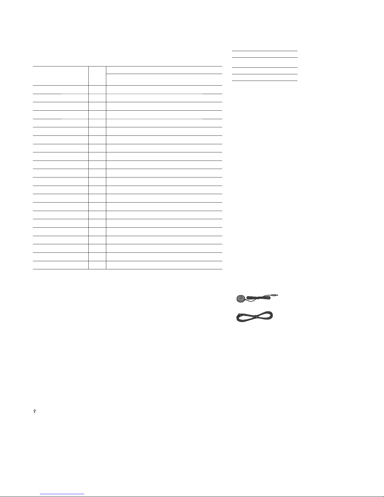
Supplied accessories
• Startup Guide
• Help Guide
• Reference Guide (specifications and precautions)
• Remote control (1)
• R03 (size-AAA) batteries (2)
• Optimizer microphone (1)
• FM wire antenna (aerial) (1)
STR-DN860/DN1060
3
NOTES ON CHIP COMPONENT REPLACEMENT
• Never reuse a disconnected chip component.
•
Notice that the minus side of a tantalum capacitor may be damaged
by heat.
SAFETY CHECK-OUT
After correcting the original service problem, perform the following
safety check before releasing the set to the customer:
Check the antenna terminals, metal trim, “metallized” knobs,
screws, and all other exposed metal parts for AC leakage.
Check leakage as described below.
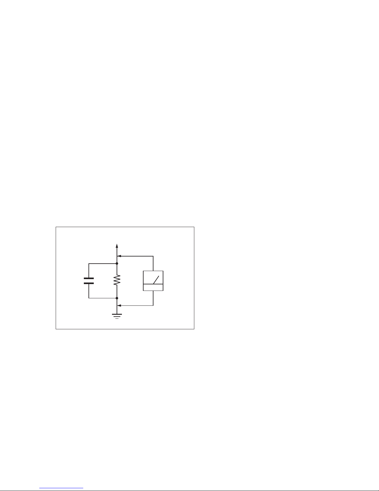
LEAKAGE TEST
The AC leakage from any exposed metal part to earth ground and
from all exposed metal parts to any exposed metal part having a
return to chassis, must not exceed 0.5 mA (500 microamperes.).
Leakage current can be measured by any one of three methods.
1. A commercial leakage tester, such as the Simpson 229 or RCA
WT-540A. Follow the manufacturers’ instructions to use these
instruments.
2. A battery-operated AC milliammeter. The Data Precision 245
digital multimeter is suitable for this job.
3. Measuring the voltage drop across a resistor by means of a
VOM or battery-operated AC voltmeter. The “limit” indication
is 0.75 V, so analog meters must have an accurate low-voltage
scale. The Simpson 250 and Sanwa SH-63Trd are examples
of a passive VOM that is suitable. Nearly all battery operated
digital multimeters that have a 2 V AC range are suitable. (See
Fig. A)
1.5 kΩ0.15 μF
AC
voltmeter
(0.75 V)
To Exposed Metal
Parts on Set
Earth Ground
Fig. A. Using an AC voltmeter to check AC leakage.
SAFETY-RELATED COMPONENT WARNING!
COMPONENTS IDENTIFIED BY MARK 0 OR DOTTED LINE
WITH MARK 0 ON THE SCHEMATIC DIAGRAMS AND IN
THE PARTS LIST ARE CRITICAL TO SAFE OPERATION.
REPLACE THESE COMPONENTS WITH SONY PARTS
WHOSE PART NUMBERS APPEAR AS SHOWN IN THIS
MANUAL OR IN SUPPLEMENTS PUBLISHED BY SONY.
ATTENTION AU COMPOSANT AYANT RAPPORT
À LA SÉCURITÉ!
LES COMPOSANTS IDENTIFIÉS PAR UNE MARQUE 0 SUR
LES DIAGRAMMES SCHÉMATIQUES ET LA LISTE DES
PIÈCES SONT CRITIQUES POUR LA SÉCURITÉ DE FONCTIONNEMENT. NE REMPLACER CES COMPOSANTS QUE
PAR DES PIÈCES SONY DONT LES NUMÉROS SONT DONNÉS DANS CE MANUEL OU DANS LES SUPPLÉMENTS
PUBLIÉS PAR SONY.

STR-DN860/DN1060
4
1. SERVICING NOTES ............................................. 5
2. DISASSEMBLY
2-1. Disassembly Flow ........................................................... 9
2-2. Case (Entry) (DN860) ..................................................... 10
2-3. Case (Stepup) (DN1060) ................................................ 10
2-4. Card WLAN/BT COMBO (DN860)............................... 11
2-5. Card WLAN/BT COMBO (DN1060)............................. 12
2-6. MB-1409 Board (DN860) ............................................... 13
2-7. MB-1409 Board (DN1060) ............................................. 14
2-8. Front Panel Section ......................................................... 15
2-9. Back Panel Section (DN860) .......................................... 16
2-10. Back Panel Section (DN1060) ........................................ 17
2-11. STANDBY Board, MAIN Board Section ....................... 18
2-12. MAIN Board ................................................................... 19
3. TEST MODE ............................................................ 20
4. FM TUNER CHECK ............................................. 28
5. TROUBLESHOOTING .......................................... 29
6. DIAGRAMS
6-1. Block Diagram - ANALOG AUDIO Section - ............... 35
6-2. Block Diagram - DIGITAL Section (1/2) - ..................... 36
6-3. Block Diagram - DIGITAL Section (2/2) - ..................... 37
6-4. Block Diagram - AMP Section - ..................................... 38
6-5. Block Diagram - ANALOG VIDEO/USB Section - ...... 39
6-6. Block Diagram - DIGITAL VIDEO Section - ................ 40
6-7. Block Diagram - DISPLAY/POWER Section - .............. 41
6-8. Printed Wiring Board
- MB-1409 Board - (Component side) - ......................... 43
6-9. Printed Wiring Board
- MB-1409 Board - (Conductor side) - ........................... 44
6-10. Schematic Diagram - MB-1409 Board (1/18) - .............. 45
6-11. Schematic Diagram - MB-1409 Board (2/18) - .............. 46
6-12. Schematic Diagram - MB-1409 Board (3/18) - .............. 47
6-13. Schematic Diagram - MB-1409 Board (4/18) - .............. 48
6-14. Schematic Diagram - MB-1409 Board (5/18) - .............. 49
6-15. Schematic Diagram - MB-1409 Board (6/18) - .............. 50
6-16. Schematic Diagram - MB-1409 Board (7/18) - .............. 51
6-17. Schematic Diagram - MB-1409 Board (8/18) - .............. 52
6-18. Schematic Diagram - MB-1409 Board (9/18) - .............. 53
6-19. Schematic Diagram - MB-1409 Board (10/18) - ............ 54
6-20. Schematic Diagram - MB-1409 Board (11/18) - ............ 55
6-21. Schematic Diagram - MB-1409 Board (12/18) - ............ 56
6-22. Schematic Diagram - MB-1409 Board (13/18) - ............ 57
6-23. Schematic Diagram - MB-1409 Board (14/18) - ............ 58
6-24. Schematic Diagram - MB-1409 Board (15/18) - ............ 59
6-25. Schematic Diagram - MB-1409 Board (16/18) - ............ 60
6-26. Schematic Diagram - MB-1409 Board (17/18) - ............ 61
6-27. Schematic Diagram - MB-1409 Board (18/18) - ............ 62
6-28. Printed Wiring Board
- MAIN Board - (Component side) - .............................. 63
6-29. Printed Wiring Board
- MAIN Board - (Conductor side) - ................................ 64
6-30. Schematic Diagram - MAIN Board (1/5) - ..................... 65
6-31. Schematic Diagram - MAIN Board (2/5) - ..................... 66
6-32. Schematic Diagram - MAIN Board (3/5) - ..................... 67
6-33. Schematic Diagram - MAIN Board (4/5) - ..................... 68
6-34. Schematic Diagram - MAIN Board (5/5) - ..................... 69
TABLE OF CONTENTS
6-35. Printed Wiring Boards - PANEL Section - ..................... 70
6-36. Schematic Diagram - PANEL Section - .......................... 71
6-37. Printed Wiring Board - DCDC Board - .......................... 72
6-38. Schematic Diagram - DCDC Board - ............................. 73
6-39. Printed Wiring Board - STANDBY Board - ................... 74
6-40. Schematic Diagram - STANDBY Board - ...................... 75
6-41. Printed Wiring Board - FRONTJACK Board - .............. 76
6-42. Schematic Diagram - FRONTJACK Board - ................. 76
6-43. Printed Wiring Board
- FRONT HDMI Board (DN1060) - ............................... 76
6-44. Schematic Diagram
- FRONT HDMI Board (DN1060) - ............................... 77
6-45. Printed Wiring Board - POWERKEY Board -................ 77
6-46. Schematic Diagram - POWERKEY Board - .................. 77
6-47. Printed Wiring Board - HP Board - ................................. 78
6-48. Schematic Diagram - HP Board - ................................... 78
7. EXPLODED VIEWS
7-1. Case Section .................................................................... 120
7-2. MB-1409 Board (DN860) ............................................... 121
7-3. MB-1409 Board (DN1060) ............................................. 122
7-4. Front Panel Section ......................................................... 123
7-5. Back Panel Section ......................................................... 124
7-6. Chassis Section (DN860) ................................................ 125
7-7. Chassis Section (DN1060) .............................................. 126
8. ELECTRICAL PARTS LIST .............................. 127
STR-DN860/DN1060
5
SECTION 1
SERVICING NOTES
UNLEADED SOLDER
Boards requiring use of unleaded solder are printed with the
lead-free mark (LF) indicating the solder contains no lead.
(Caution: Some printed circuit boards may not come printed with
the lead free mark due to their particular size)
: LEAD FREE MARK
Unleaded solder has the following characteristics.
• Unleaded solder melts at a temperature about 40 °C higher
than ordinary solder.
Ordinary soldering irons can be used but the iron tip has to be
applied to the solder joint for a slightly longer time.
Soldering irons using a temperature regulator should be set to
about 350 °C.
Caution: The printed pattern (copper foil) may peel away if
the heated tip is applied for too long, so be careful!
• Strong viscosity
Unleaded solder is more viscous (sticky, less prone to fl ow)
than ordinary solder so use caution not to let solder bridges
occur such as on IC pins, etc.
• Usable with ordinary solder
It is best to use only unleaded solder but unleaded solder may
also be added to ordinary solder.
NOTE OF REPLACING THE IC101, IC102, IC103,
IC110, IC301, IC307, IC308, IC309, IC310, IC313,
IC2001, IC3700 (DN860), IC5010, IC6000 (DN1060),
IC6501, IC7100, IC7400 AND IC7440 ON THE
MB-1409 BOARD
IC101, IC102, IC103, IC110, IC301, IC307, IC308, IC309, IC310,
IC313, IC2001, IC3700 (DN860), IC5010, IC6000 (DN1060),
IC6501, IC7100, IC7400 and IC7440 on the MB-1409 board
cannot exchange with single. When these parts on the MB-1409
board are damaged, exchange the entire mounted board.
NOTE OF REPLACING THE IC1906, IC1912, IC1913,
IC1914 AND IC1915 ON THE DCDC BOARD
IC1906, IC1912, IC1913, IC1914 and IC1915 on the DCDC board
cannot exchange with single. When these parts on the DCDC
board are damaged, exchange the entire mounted board.
NOTE OF REPLACING THE IC1236 ON THE MAIN
BOARD
IC1236 on the MAIN board cannot exchange with single. When
this part on the MAIN board is damaged, exchange the entire
mounted board.
MODEL IDENTIFICATION
–BACK PANEL–
Model
Part No.
DN1060: US, Canadian
4-547-190-0
[]
DN1060: AEP, UK
4-547-190-1
[]
DN1060: Australian
4-547-190-2
[]
DN860: US, Canadian
4-547-191-0
[]
DN860: AEP, UK
4-547-191-1
[]
DN860: Australian
4-547-191-2
[]
DN860: Taiwan
4-547-191-3
[]
NOTE OF REPLACING THE WLAN/BT COMBO CARD
When the WLAN/BT COMBO CARD is exchanged, the MAC
address has been changed.
Please print and cut out the following explanations, and return it
with the unit that complete the repair.
MAC address of this receiver has been changed by
this repair.
The customer who use the MAC address fi ltering
function of connected access point equipment please
set it again.
MAC address is possible to confi rm on the System
Information.
screen of this unit.
Please refer to “Adjusting Settings”
---
> “Network
Settings” on the Help Guide for details.
Help Guide Links :
AEP, UK Models :
http://rd1.sony.net/help/ha/strdn10686/h_eu/
Except AEP, :
http://rd1.sony.net/help/ha/strdn10686/h_zz/
UK Models
Please check the basic operation for wired LAN, Wireless
LAN and USB after the repair completed.
NOTE OF DELETING THE PRODUCT REGISTR ATION
ON SEN (INTERNET MUSIC SERVICES)
It is needed to delete the product registration on SEN (INTERNET
MUSIC SERVICES) by checking the “Device ID” which have 12
digits hexadecimal number. The procedure of checking “Device
ID” can be followed as below:
1. Press [HOME] key of the remote commander, the message
“HOME MENU” appears.
2. Select “Setup” and press [ENTER] key.
3. Select “System Settings” and press [ENTER] key.
4. Select “System Information” and press [ENTER] key.
5. Device ID will shown on the display.
Device ID: XXXX XXXX XXXX (12 digits hexadecimal
number).
If it is needed to delete the customer’s registration, please contact
the Service Headquarter with Device ID information.
Part No.
STR-DN860/DN1060
6
NOTE OF REPLACING THE Q1550, Q1551, Q1600,
Q1601, Q1650, Q1651, Q1700, Q1701, Q1750, Q1751,
Q1800, Q1801, Q1850 AND Q1851 ON THE MAIN
BOARD
Replacement of Q1550, Q1551, Q1600, Q1601, Q1650, Q1651,
Q1700, Q1701, Q1750, Q1751, Q1800, Q1801, Q1850 and
Q1851 on the MAIN board used in this unit requires L type screw
driver.
L type screw driver
(e.g Compact 90 degree right
angled ratchet screwdriver (dr-05))
NOTE OF REPLACING THE IC1906, IC1911, IC1912,
IC1913, IC1914 AND IC1915 ON THE DCDC BOARD
Replacement of IC1906, IC1911, IC1912, IC1913, IC1914 and
IC1915 on the DCDC Board used in this unit required to unsolder
the grounding wire on the DCDC Board.
Grounding wire
After replaced the IC1906, IC1911, IC1912, IC1913, IC1914 and
IC1915, have to solder back the grounding wire on the DCDC
Board properly before turn on the set (refer image provided
below).
(Caution: If insuffi cient solder occured for the grounding wire in
DCDC Board, it may caused the set intermittent turn on/off and
will spoil the MB Board)
NG (Insufficient solder)OK
Grounding wire area (Conductor View)
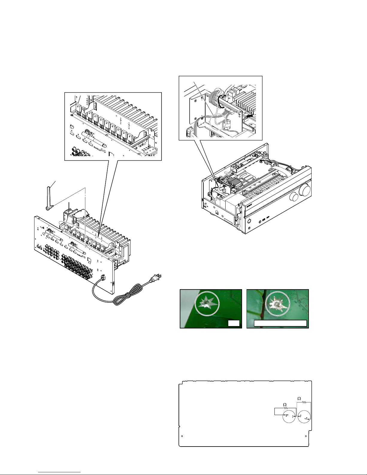
CAPACITOR ELECTRICAL DISCHARGE PROCESSING
When checking the board, for the electric shock prevention,
connect the resistors to both ends of respective capacitors (C930
and C931 on the MAIN board) to discharge the capacitors.
800 /5 W
800
/5 W
C930C931
– MAIN Board (Conductor Side) –

STR-DN860/DN1060
7
If there is a malfunction, a message appears on
the display panel. You can check the condition
of the system by the message. If any problem
persists, consult your nearest Sony dealer.
PROTECTOR
USB FAIL
Error messages
The receiver will automatically turn off
after a few seconds. Check the followings:
s There may be an electrical surge or
power failure. Unplug the AC power cord
(mains lead) and then plug in the cord
again after 30 minutes.
s The receiver is covered and the ventila-
tion holes are blocked. Remove the object
covering the ventilation holes of the
receiver.
s The impedance of the connected speakers
is below the rated impedance range
indicated on the back panel of the
receiver. Reduce the volume level.
s Unplug the AC power cord (mains lead)
and let the receiver cool down for 30
minutes while performing the following
troubleshooting:
– Disconnect all of the speakers and
subwoofer.
– Check that the speaker wires are tightly
twisted on both ends.
– Connect the front speaker first, increase
the volume level and operate the
receiver for at least 30 minutes until
it completely warms up. Then, connect
each additional speaker one by one and
test each additional speaker until you
detect which speaker is causing the
protection error.
After checking the above items and fixing
any problems, plug in the AC power cord
(mains lead) and turn on the receiver. If
the problem persists, consult your nearest
Sony dealer.
An over-current from the (USB) port was
detected. Disconnect all USB devices as
prompted in the warning message and
close the message.
For other messages, see “List of messages
after Auto Calibration measurements”.
Reverting to the factory
default settings
Note
You can clear all memorized settings and
restore the receiver to the factory default
settings by the following procedure. This
procedure can also be used to initialize
the receiver before you use it for the first
time.
Be sure to use the buttons on the receiver
to perform this operation.
1. Turn off the receiver.
2. Hold down "/1 (on/standby) on the
receiver for 5 seconds.
[CLEARING] appears on the display
panel for a while, then changes to
[CLEARED!].
s It takes a few minutes for the memory
to be cleared completely. Do not turn
the receiver off until [CLEARED!]
appears on the display panel.
Resetting sound fields
to the default settings
Be sure to use the buttons on the receiver
to perform this operation.
1. Turn off the receiver.
2. Hold down MUSIC and press &/1
(on/standby) on the receiver.
[S.F. CLEAR] appears on the display
panel and all sound fields are reset to
their default setting.
STR-DN860/DN1060
8
NOTE OF REPLACING MB-1409 BOARD OR WLAN/
BT COMBO CARD
When the MB-1409 board or WLAN/BT COMBO card are
replaced, please execute the below service mode.
Procedure:
While pressing [DISPLAY] button, press and release the [MUSIC],
[A.F.D/2CH], [MOVIE] button in order, the message “SERVICE
IN” appears.
Next, go to service menu and execute “[1] Bluetooth Enable” and
“[3] Write Bluetooth device address to Registry”.
Finally check one touch NFC listening function at normal power
on.
Note: The operation in this mode must use a remote commander
and TV monitor.
1. Connect this unit with TV monitor.
2. Press the [
?/1
] button to turn the power on.
3. While pressing [DISPLAY] button, press and release the
[MUSIC], [A.F.D/2CH], [MOVIE] button in order, the
message “SERVICE IN” appears.
4. Enter the SVC service mode. The OSD menu on TV monitor
can be operated by remote commander.
5. Press [m] and Enter Diag.
6. Press [,] and Enter Bluetooth Device Test (Screen 1).
7. Enter [1] Bluetooth Enable, wait until the display show
“ Status : Bluetooth Enable Successful ” (Screen 2).
8. Enter [3] Write Bluetooth device address to Registry, wait until
the display show “Bluetooth Device Address” and “Status :
Write Successfull” (Screen 3).
9. Press the [RETURN] button on the remote commander to
select “Wireless LAN Test” (Screen 4).
10. Press the [ ] button on the remote commander to select
“[5] Write P2P address to Registry”.
11. Press the [ ] button on the remote commander, wait until the
display show “Status: Write Successful!” (Screen 5).
12. Press the [m] button on the remote commander to select
“(6) P2P Registry Check” (Screen 6).
13. Press the [ ] button on the remote commander to check the
P2P device address is the same as shown in Screen 5.
(Displayed characters/values in the following fi gure are
example)
14. Press the [RETURN] button on the remote commander and
select Factory Initialize (go to Screen 7).
15. The set will turn off automatically.
Diag
Category: Bluetooth Device Test
Diag
Category: Bluetooth Device Test
[1] Bluetooth Enable
[2] Bluetooth Disable
[3] Write Bluetooth device address to Registry
[4] Bluetooth Inquiry Test
Status : Bluetooth Enable Successful!
HELP: [UP] [DOWN] [ENT] [RET]
(Screen 1)
(Screen 2)
Diag
Category: Wireless LAN Test
Diag
Category: Wireless LAN Test
[1] Show WLAN HwInfo
[2] Connect to AccessPoint
[3] Start Display RSSI Value
[4] Start Ping Test
[5] Write P2P address to Registry
[6] P2P Registry Check
P2P device address : xx:xx:xx:xx:xx:xx
Status : Write Successful!
Status : Write Fail!
Diag
Category: Wireless LAN Test
[1] Show WLAN HwInfo
[2] Connect to AccessPoint
[3] Start Display RSSI Value
[4] Start Ping Test
[5] Write P2P address to Registry
[6] P2P Registry Check
P2P device address : xx:xx:xx:xx:xx:xx
HELP: [UP] [DOWN] [ENT] [RET]
(Screen 4)
(Screen 5)
(Screen 6)
(Screen 7)
(Screen 3)
Diag
Category: Bluetooth Device Test
[1] Bluetooth Enable
[2] Bluetooth Disable
[3] Write Bluetooth device address to Registry
[4] Bluetooth Inquiry Test
Bluetooth device address : 00:01:36:23:FD:CF
Status : Write Successful!
HELP: [UP] [DOWN] [ENT] [RET]
Service Mode Menu
[1] Diag
[2] Log
[3] Factory Initialize
[4] Network --> Not Support In This Model
[5] Version Up
[6] System Information
[7] EMC Test Mode
[8] Drive --> Not Support In This Model
[9] HDD mode
[10] RF Test Mode
HELP: [DOWN] [ENT]
STR-DN860/DN1060
9
SECTION 2
DISASSEMBLY
• This set can be disassembled in the order shown below.
2-1. DISASSEMBLY FLOW
2-2. CASE (ENTRY) (DN860)
(Page 10)
2-7. MB-1409 BOARD (DN1060)
(Page 14)
2-5. CARD WLAN/BT COMBO
(DN1060)
(Page 12)
2-3. CASE (STEPUP) (DN1060)
(Page 10)
2-4. CARD WLAN/BT COMBO
(DN860)
(Page 11)
2-6. MB-1409 BOARD (DN860)
(Page 13)
2-8. FRONT PANEL SECTION
(Page 15)
2-9. BACK PANEL SECTION (DN860)
(Page 16)
2-10. BACK PANEL SECTION (DN1060)
(Page 17)
2-11. STANDBY BOARD,
MAIN BOARD SECTION
(Page 18)
2-12. MAIN BOARD
(Page 19)
SET
STR-DN860/DN1060
10
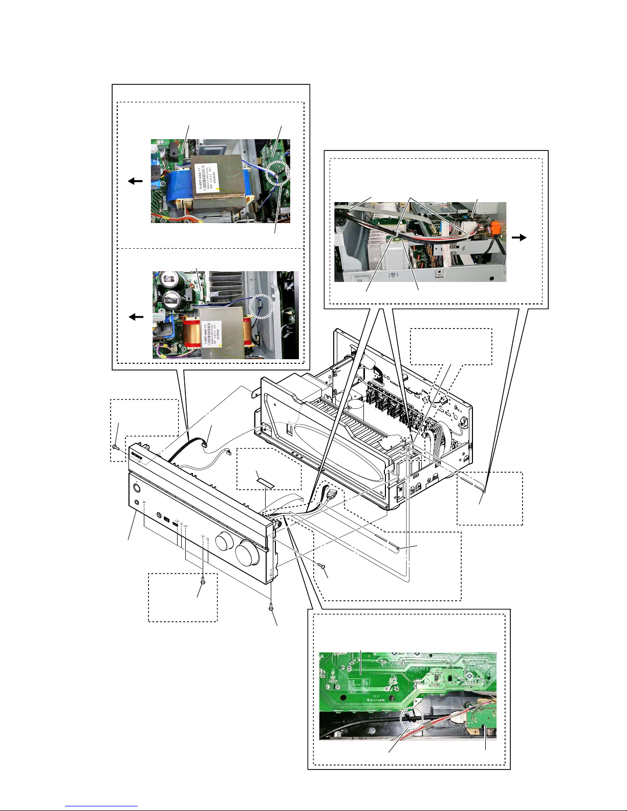
Note: Follow the disassembly procedure in the numerical order given.
2-2. CASE (ENTRY) (DN860)
3 three screws
(+BVTP 3 u 8)
4
2 three screws
(B-TYPE 4 u 8)
5 case (entry)
1 three screws
(B-TYPE 4 u 8)
4
2-3. CASE (STEPUP) (DN1060)
3 four screws
(+BVTP 3 u 8)
4
2 three screws
(B-TYPE 4 u 8)
5 case (stepup)
1 three screws
(B-TYPE 4 u 8)
4
STR-DN860/DN1060
11
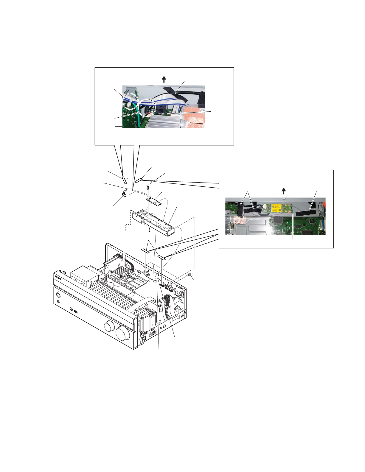
2-4. CARD WLAN/BT COMBO (DN860)
qa card WLAN/BT combo
6 CON4 (1P)
7 CON5 (1P)
9 bracket,
module (bottom)
2 CN502 (5P)
5 cushion (R)
4 cushion (R)
3 cushion (R)
8 two screws
(+BVTP 3 u 8)
0 one screw
(+BVTP 3 u 8)
rear side
DCDC
board
MB-1409
board
cable tie
clamp
cushion (R)
:LUHVHWWLQJ
Note: Process so that lead wire
does not contact CN301 and W1990
rear side
bracket, module (bottom)
cushion (R)
cushion (R)
:LUHVHWWLQJ
86&1'
1 Wire is removed
from the clamp.
• Abbreviation
CND : Canadian model
STR-DN860/DN1060
12
2-5. CARD WLAN/BT COMBO (DN1060)
9 card WLAN/BT combo
4 CON4 (1P)
5 CON5 (1P)
7 bracket,
module (bottom)
1 CN502 (5P)
3 cushion (R)
2 cushion (R)
6 two screws
(+BVTP 3 u 8)
8 one screw
(+BVTP 3 u 8)
Note: Process so that lead wire
does not contact CN301 and W1990
rear side
DCDC board
MB-1409
board
cushion (R)
rear side
bracket, module (bottom)
cushion (R)
cushion (R)
:LUHVHWWLQJ
:LUHVHWWLQJ
STR-DN860/DN1060
13
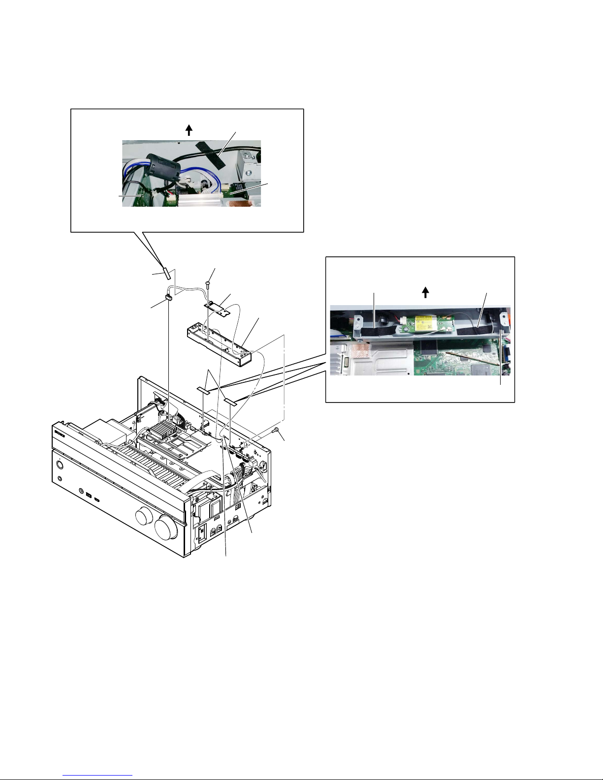
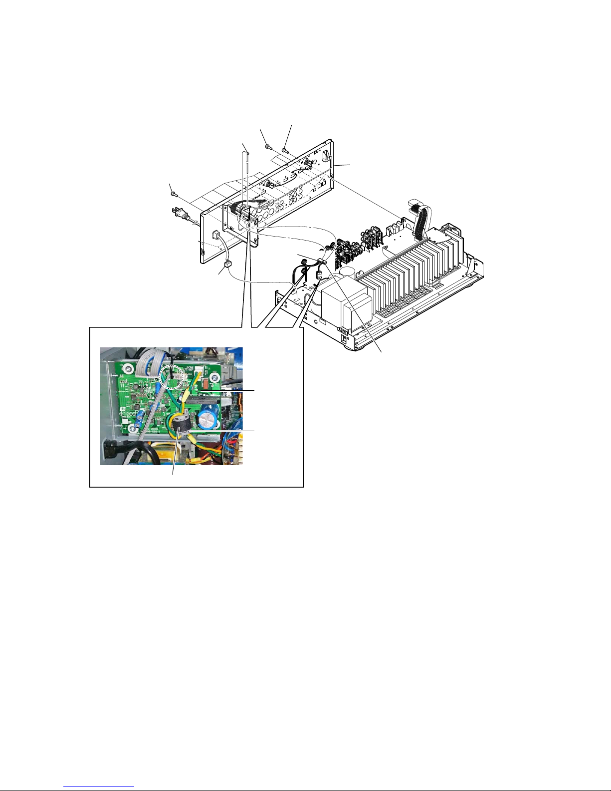
2-6. MB-1409 BOARD (DN860)
5 CN501 (5P)
6 CN301 (11P)
E
F
G
E
H
I
F
G
0 one screw
(+BVTP 3 u 8)
qa one screw
(+BVTP 3 u 8)
qa two screws
(+BVTP 3 u 8)
qs clamp
qs clamp
qa three screws
(+BVTP 3 u 8)
qd bracket, HDMI
(N86)
qf four screws
(+BVTP 3 u 8)
qh heat sink (HDMI-B)
qj sheet, radiation
qk MB-1409 board
qg heat sink (HDMI-A)
H
I
1 wire (flat type)
(27 core) (CN3004)
4 wire (flat type)
(19 core) (CN8001)
3 CN8000 (13P)
2 wire (flat type)
(22 core) (CN8002)
7 six screws
(+B 3 u 5)
8 one screw
(+BVTP 3 u 8)
9 two screws
(+BVTP 3 u 8)
MB-1409 board
pin, lead
pin, lead
DISPLAY board
MB-1409 board
pin, lead and cable tie
:LUHVHWWLQJ
:LUHVHWWLQJ
Note: Process so that lead wire does
not contact CN502
rear side
STR-DN860/DN1060
14
2-7. MB-1409 BOARD (DN1060)
7 CN501 (5P)
8 CN301 (11P)
E
F
G
E
H
I
J
F
G
qs two screws
(+BVTP 3 u 8)
qj two screws (+BVTP 3 u 8)
qd two screws
(+BVTP 3 u 8)
qd one screws
(+BVTP 3 u 8)
qd one screw (+BVTP 3 u 8)
qh bracket,
HDMI (N86)
qd one screw (+BVTP 3 u 8)
qg clamp
qg clamp
wa bracket,
beam (N104)
ws four screws
(+BVTP 3 u 8)
wf heat sink (HDMI-B)
wg sheet, radiation
wh MB-1409 board
wd heat sink (HDMI-A)
ql tape
qk rivet (DIA. 3),
nylon
w; copper shield
(N106)
H
J
I
3 wire (flat type)
(27 core) (CN3004)
6 wire (flat type)
(19 core) (CN8001)
1 HDMI cable
(CN3501)
5 CN8000 (13P)
2 CN3500
(7P)
4 wire (flat type)
(22 core) (CN8002)
9 seven screws
(+B 3 u 5)
0 one screw
(+BV 3 u 8 CU)
(US, CND)
one screw
(+BVTP 3 u 8)
(AEP, UK, AUS)
qa two screws
(+BVTP 3 u 8)
(AEP, UK, AUS)
qd one screw (+BVTP 3 u 8)
MB-1409 boardDCDC board
Note: Process so that lead wire does
not contact CN502
:LUHVHWWLQJ
DISPLAY board
MB-1409 board
pin, lead
rear side
K
L
K
L
qf Cut the cable tie
pin, lead and
cable tie
cable tie and clamp
:LUHVHWWLQJ
• Abbreviation
AUS : Australian model
STR-DN860/DN1060
15
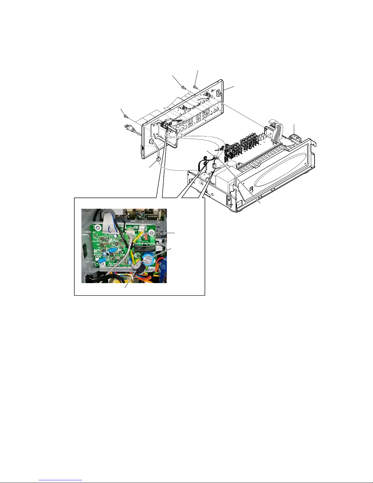
2-8. FRONT PANEL SECTION
SUPPORT boardpin, lead
MAIN board
DISPLAY board
FRONT HDMI board
MB-1409 board
pin, lead
cable tiecushion (R)
:LUHVHWWLQJ
:LUHVHWWLQJ
:LUHVHWWLQJ
2 Wire is removed
from the pin, lead.
3 cushion (R)
4 CN1391
(4P)
7 front panel
section
5 five screws
(+BVTP 3 u 8)
6 one screw
(+BVTP 3 u 8)
6 one screw
(+BVTP 3 u 8)
5 two screws
(+BVTP 3 u 8)
rear side
rear side
1 Cut the
cable tie
1 Cut the
cable tie
(DN1060)
(DN1060)
(DN1060)
(DN1060)
(DN1060)
(DN1060)
(DN1060)
(DN1060)
(DN1060)
(DN860)
MAIN board
POWERKEY
board
pin, lead
rear side
STR-DN860/DN1060
16
2-9. BACK PANEL SECTION (DN860)
1 CNP901
(3P)
3 CN1905
(4P)
4 CN1907 (2P)
5 five screws
(+BVTP 3 u 8)
6 three screws
(+BVTP 3 u 8)
6 eight screws
(+BVTP 3 u 8)
7 back panel section
2 Cut the cable tie
cushion (R)
DCDC board
:LUHVHWWLQJ
clamp,
sleeve ferrite
STR-DN860/DN1060
17
2-10. BACK PANEL SECTION (DN1060)
• Abbreviation
AUS : Australian model
CND : Canadian model
1 CNP901
(3P)
2 CN1905 (4P)
3 CN1907 (2P)
4 seven screws
(+BVTP 3 u 8)
4 eight screws
(+BVTP 3 u 8)
5 four screws (+BVTP 3 u 8)
(US, CND)
four screws (BV/RING)
(AEP, UK, AUS)
6 back panel section
cushion (R)
DCDC board
:LUHVHWWLQJ
clamp,
sleeve ferrite
STR-DN860/DN1060
18
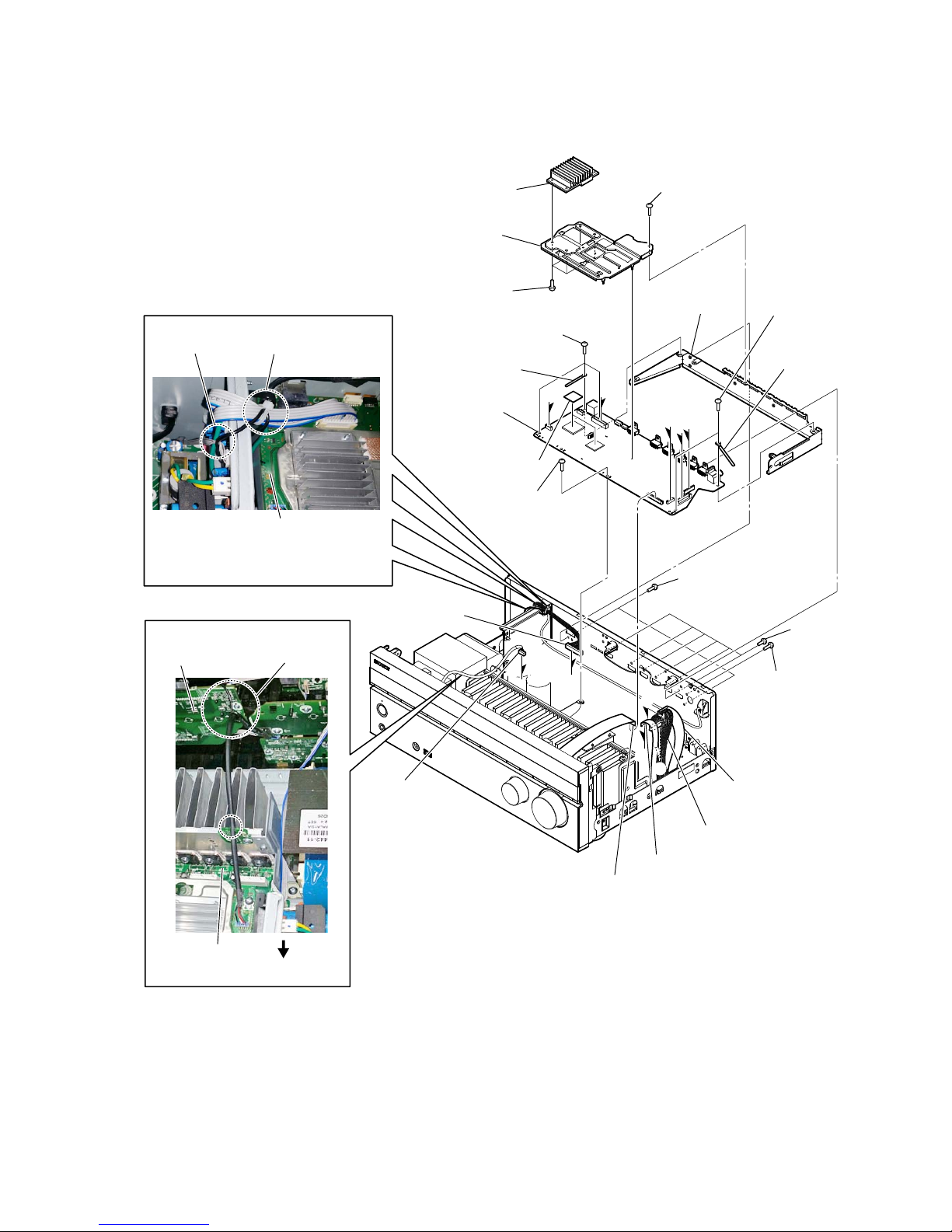
7 two screws
(+BVTP 3 u 8)
7 two screws
(+BVTP 3 u 8)
9 MAIN BOARD
section
8 one screw
(+BVTP 3 u 8)
2 four screws
(+BVTP 3 u 8)
3 STANDBY board
1 CNP902 (4P)
5 CNP920 (5P)
6 CNP930 (5P)
4 Wire is removed
from the pin, lead.
:LUHVHWWLQJ
pin, lead
MAIN board
rear side
2-11. STANDBY BOARD, MAIN BOARD SECTION
STR-DN860/DN1060
19
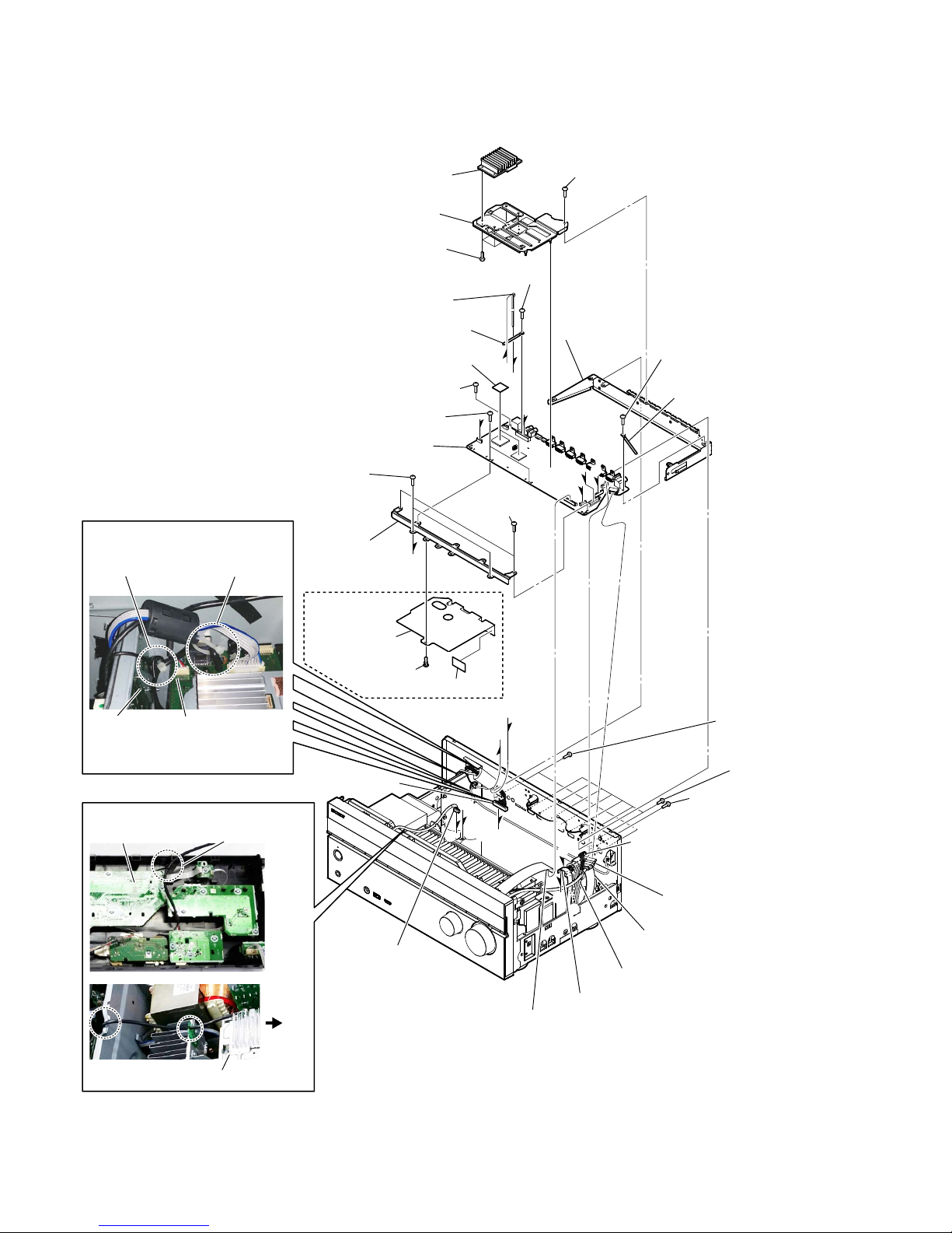
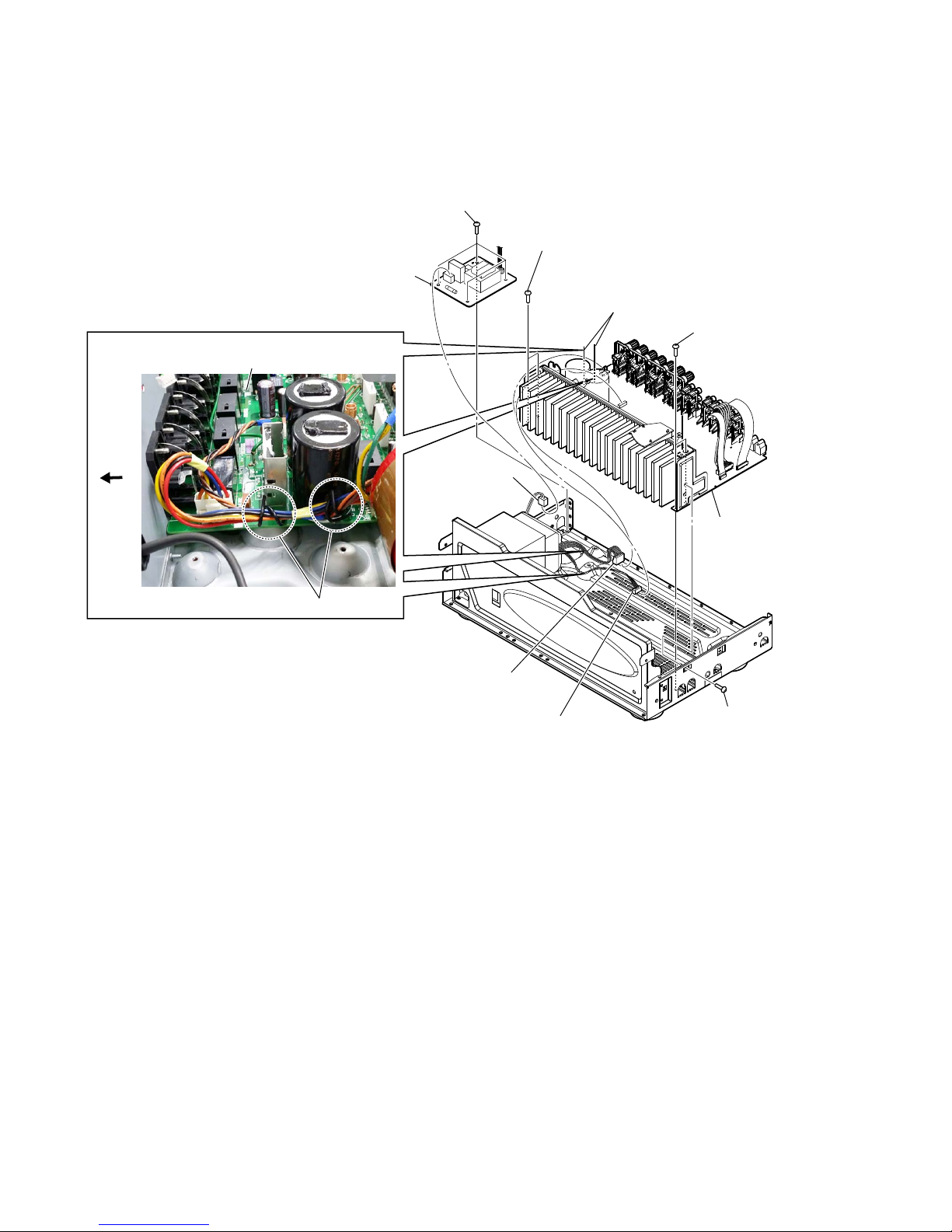
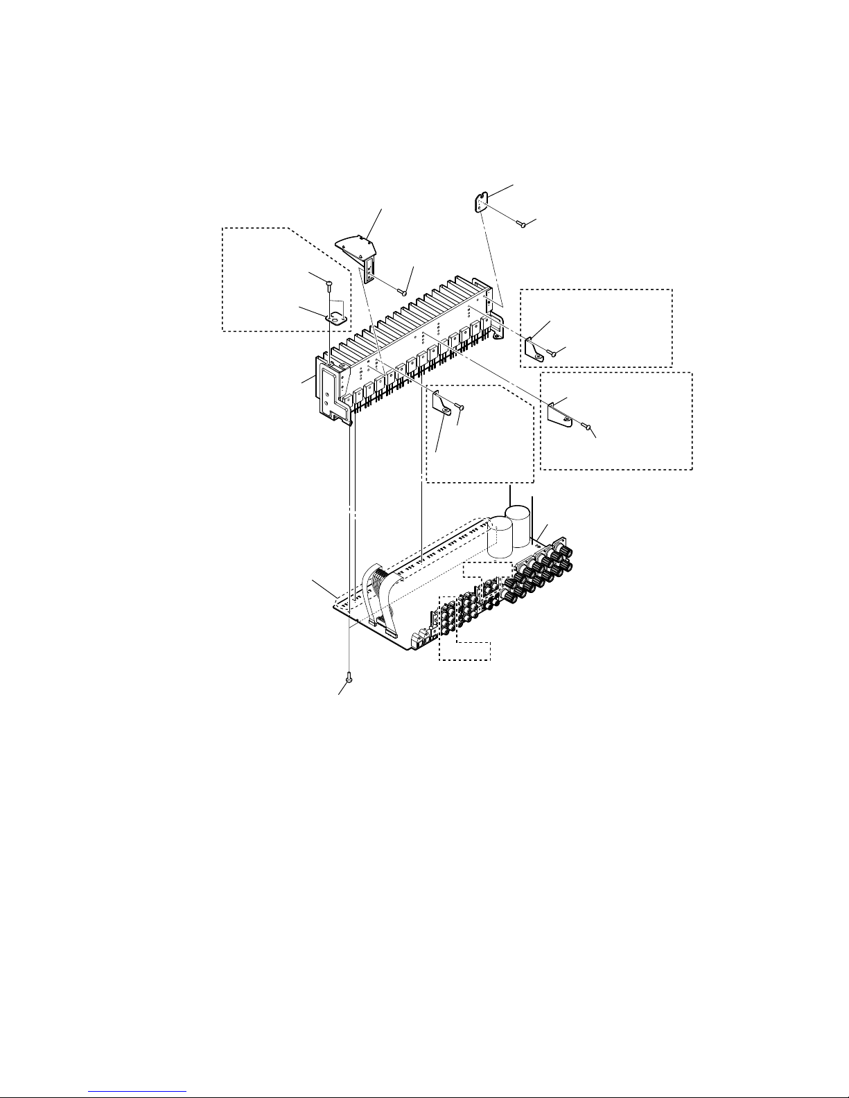
2-12. MAIN BOARD
Note : This illustration sees the MAIN board from back side.
9 heat sink section
qa two screws
(+BVTP 3 u 8)
qs MAIN board
0 Remove the
forty-two solders.
1 one screw
(+BVTP 3 u 8)
2 INSULATION board
4 USB INSULATION
board
3 one screw
(+BVTP 3 u 8)
7 one screw
(+BVTP 3 u 8)
7 one screw
(+BVTP 3 u 8)
8 bracket, HDMI support
7 one screw
(+BVTP 3 u 8)
5 two screws
(+BVTP 3 u 8)
6 SUPPORT
board
8 bracket, support beam
8 bracket,
support beam
(DN1060)
(DN1060)
(DN1060)
(DN1060)
(DN1060)
(DN860)
STR-DN860/DN1060
20
SECTION 3
TEST MODE
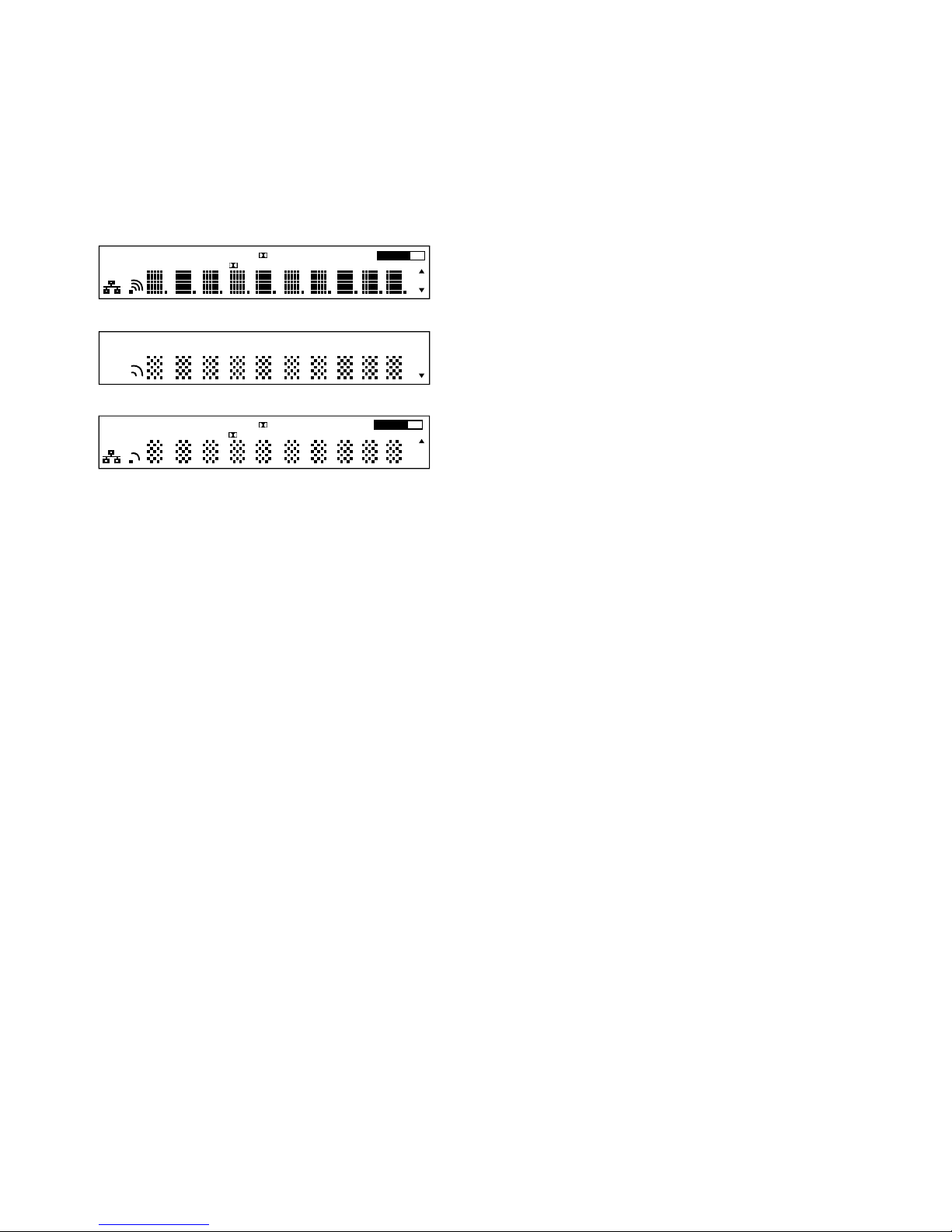
VACUUM FLUORESCENT DISPLAY TEST MODE
All fl uorescent segments are tested.
When this test is activated, all segments light on at the same time,
then each segment lights on one after another.
Procedure:
While pressing [SPEAKERS] and [DIMMER] buttons simultaneously, press the [
?/1
] button to turn on the main power.
1. ALL segments light on.
HDMI ARC PARTY S.OPTIMIZER D.C.A.C.
PLII x z NEO: 6 X D.R. C. D. L.L. EQ MEM RPT
True HD DTS-HD SPA+B ST
USB BT UPDATE A.P.M.ZONE 2 3
COAX OPT
SLEEP
MHz
k Hz
dB
HDMI OUT
A + B
2. Press the [DISPLAY] button to confi rm display as below.
HDMI PARTY D.C.A.C.
II z 6 D. R.C. MEM
True HD -HD A B
ST
USB UPDATE ZONE 3
OPT
SLEEP
A B
MHz
Hz
3. Press the [DISPLAY] button to confi rm display as below.
ARC S.OPTIMIZER
PL x NEO: X D.L.L. RPT
DTS SP +
BT A.P.M. 2
COAX
EQ
HDMI OUT
A + B
k
dB
4. Press the [DISPLAY] button, all segments light off.
SOUND FIELD CLEAR MODE
The preset sound fi eld is cleared when this mode is activated.
Use this mode before returning the product to clients upon completion of repair.
Procedure:
1. While pressing [MUSIC] button, press the [
?/1
] button to
turn on the main power.
2.
The message “S.F. CLEAR” appears for a moment and initialization is performed.
SOFTWARE VERSION DISPLAY MODE
The software version is displayed.
Procedure:
1. While pressing [A.F.D./2CH] and [PURE DIRECT] buttons
simultaneously, press the [?/1] button to turn on the main
power.
2. The message “N106 XXX” appears (DN1060).
The message “N86 XXX” appears (DN860).
XXX: Area display
Each time the [DISPLAY] button is pressed, “M29.R.XXX”,
“MAIN X.XXX”, “ADV vX.XX”, “SFLASHvX.XX”,
“HDMI.TXvX.XX” and “HDMI.RXvX.XX” appear in this
order, and returns to the “N106 XXX” (DN1060) or “N86
XXX” (DN860) display.
X.XX: Software version
KEY CHECK MODE
Each button can be checked.
Procedure:
1. While pressing [SPEAKERS] and [PURE DIRECT] buttons
simultaneously, press the [
?/1
] button to turn on the main
power.
2. The message “REST 12” appears.
Every pressing of any button other than the [
?/1
] counts down
the buttons.
3. The buttons which are already counted once are not counted
again.
4. When all buttons are pressed, “REST 00” appears.
SWAP ALL MODE
The signal will be swap to all channels so that all speakers will
have sound output.
Procedure:
1. While pressing [PURE DIRECT] and [MOVIE] buttons
simultaneously, press the [
?/1
] button to turn on the main
power.
2. The message “SWAP MODE” appears.
INITIALIZE MODE
All preset contents are cleared when this mode is activated. Use
this mode before returning the product to clients upon completion
of repair.
(a) SHIPMENT MODE
Procedure:
1. While pressing [A.F.D./2CH] and [DIMMER] buttons simultaneously, press the [
?/1
] button to turn on the main power.
2. The message “CLEARING” appears and the memories are
reset to the default values.
3. When done, the message “CLEARED !” appears, the set will
power off.
(b) ALL CLEAR INITIALIZE
Procedure:
1. While pressing [A.F.D./2CH] and [DISPLAY] buttons, press
the [?/1] button to turn on the main power.
2. The message “CLEARING” appears and the memories are
reset to the default values.
3. When done, the message “CLEARED !” appears, the set will
power on.
(c) USER INITIALIZE
Procedure:
1. Turn off the receiver.
2. Hold the [
?/1
] button for 5 seconds.
3. The message “CLEARING” appears on the display.
4. After few seconds, “CLEARED !” appears.
PROTECTOR AUTO OFF
To disable auto off after protector occur.
Procedure:
1. While pressing [DISPLAY] and [MOVIE] buttons simultaneously, press the [
?/1
] button to turn on the main power.
2. “PROTEVER” appears and switch on the set.
DCAC MIC TEST MODE
To test audio output from mic input and speakers.
Procedure:
1. While pressing [MUSIC] and [DIMMER] buttons simultaneously, press the [
?/1
] button to turn on the main power.
2. The message “MIC” appears.
MIC: mode that output audio from mic input
21
STR-DN860/DN1060
HISTORY MODE
The state that the set is used is memorized.
Procedure:
1. While pressing [SPEAKERS] and [DISPLAY] buttons
simultaneously, press the [
?/1
] button to turn on the power
and “HISTORY” is displayed.
2. Each time the [ M ] [ m ] key of remote commander is pressed,
the item is switched in order as follows.
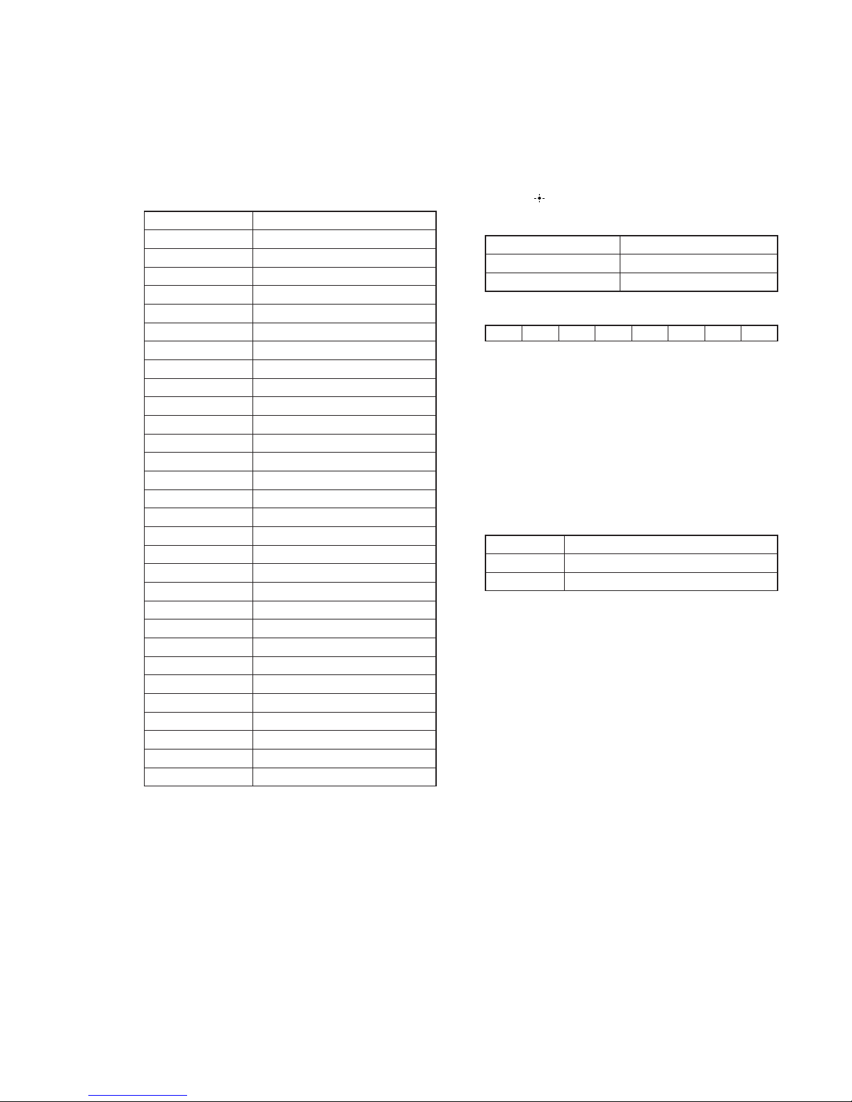
Items Display
Protector Count C O U N T x x x
Total Power ON time T x x x x x H x x M
Main Power On M x x x x x H x x M
Protector type P R O T x x x x
Sound Field S N D F I E L D
Function F U N C T I O N
Input Mode I N P M O D E
Digital Select D I G S E L E C T
Stream S T R E A M I N F O
Channel Confi g C O N F x x x x x
Headphone H E A D P H x x x
Volume V O L : x x
Muting M U T I N G : x x
Front Bass F B x x x
Front Treble F T x x x
Center Bass C B x x x
Center Treble C T x x x
Surround Bass S B x x x
Surround Treble S T x x x
Front Height Bass H B x x x
Front Height Treble H T x x x
Front Level F x x x / x x x
Center Level C x x x / x x x
Surround Level S x x x / x x x
Surround Back Level B x x x / x x x
Front Height Level H x x x / x x x
Temperature T E M P :
Total Power On T x x x x x H x x M
Main Power On M x x x x x H x x M
Power On Count R E B O X : x x
MHL VBUS MODE
This mode is to display the MHL VBUS status.
Procedure:
1. Press the [?/1] button to turn on the main power.
2. While pressing [DISPLAY] button, press and release the
[MUSIC], [MOVIE], [A.F.D./2CH] button in order, the
message “VBUS STAT” appears.
3. Press the [
] key of the remote commander.
4. Either one of the message as below appears.
Items Display
No Error N O E R R O R
Current Stopped V . E R R O R x x
HDMI IN
76543210
0 : No error 1 : VBUS output is stopped
Example:
In 7 & In 0 are error : xx = 81
In 1 & In 0 are error : xx = 03
SIRCS MODE CHANGE
To change remote control mode (AV1<=>AV2).
Procedure:
1. While pressing [MUSIC] and [PURE DIRECT] buttons
simultaneously, press the [?/1] button to turn on the main
power.
2. Either the message below appears. Select the desired mode.
Items Display
AV1 C. M O D E A V 1
AV2 C. M O D E A V 2

STR-DN860/DN1060
22
SVC SERVICE MODE
Note: The operation in this mode must use a remote commander and TV
monitor.
Setting method of the SVC service mode:
1. Connect this unit with TV monitor.
2. Press the [
?/1
] button to turn the power on.
3. While pressing [DISPLAY] button, press and release the
[MUSIC], [A.F.D/2CH], [MOVIE] button in order.
4. The message “SERVICE IN” displayed on the fl uorescent
indicator tube. The OSD menu on TV monitor can be operated
by remote commander
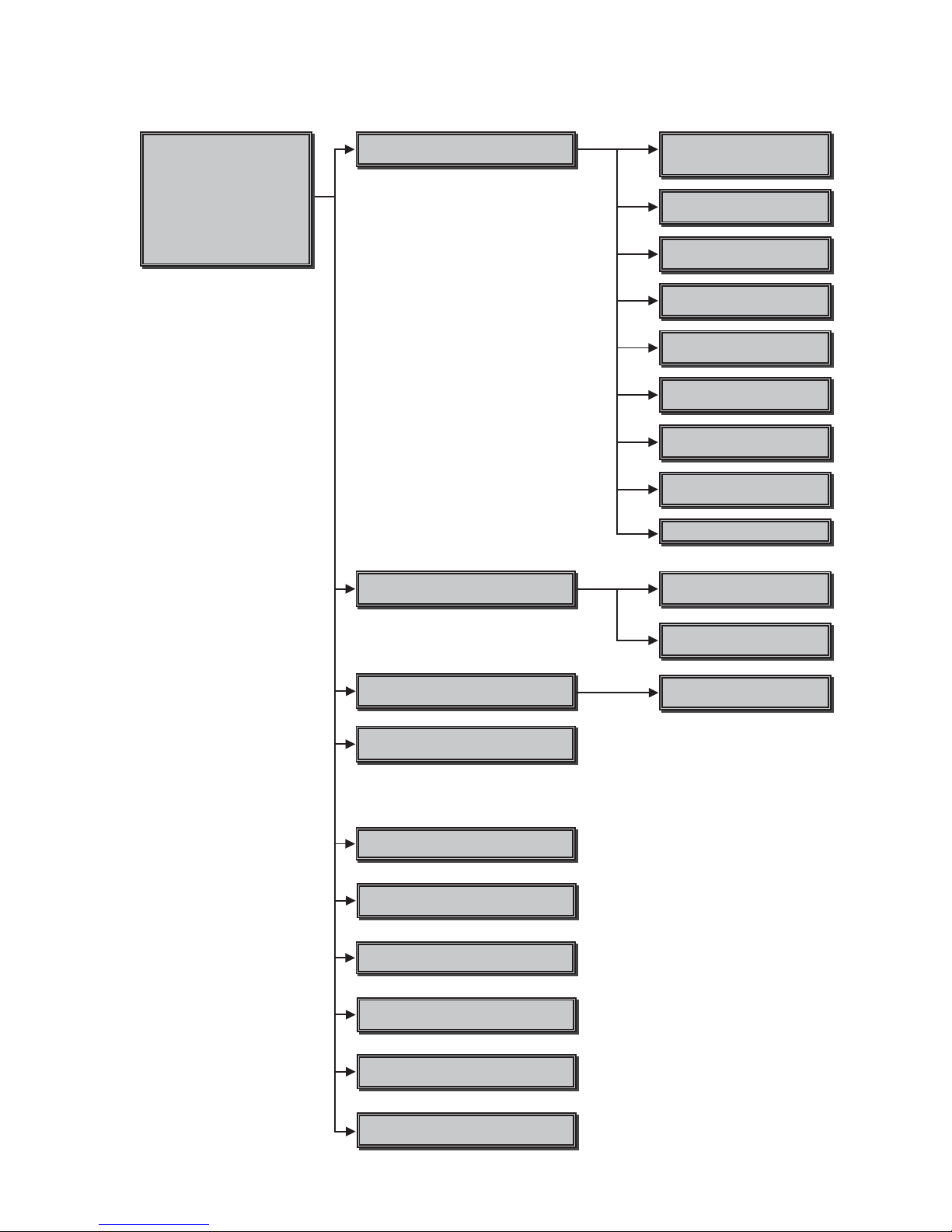
1. Main Functions
• Diag
Performs unit test of devices installed on the board.
• Log
Error log is displayed. Displayed contents can also be saved in
an USB memory device.
• Factory Initialize
Restores the unit to its factory settings.
• Network
Not used.
• Version Up
Not used.
• System Information
Displays the system information of the unit.
Displays information such as the software version, drive
information, etc.
• EMC Test Mode
Not used.
• Drive
Not used.
• HDD mode
Not used.
• RF Test Mode
Not used.
Note:
If any menu (such as easy setup page) appear on top of Service
Menu, change to below functions by Remote or Input Selector
Knob to reappear the Service Menu.
- USB, BLUETOOTH, SCREEN MIRRORING, HOME
NETWORK, INTERNET MUSIC SERVICE
23
STR-DN860/DN1060
2. Menu Tree
Version Up
Not used
System Information
Displays system information
Factory Initialize
,QLWLDOL]HGHIDXOWVHWWLQJ
LoJ
'isplays Error /RJ
Error LoJ
Displays error loJ
DiaJ
Network
1RWXVHG
+''/RJ
Device Test
86%'$&,)FRQ0,&0),,3&
([WHUQDO+'0,7UDQVFRGHUWHVW
Video Test
Not used
$udio Test
Not used
$udio Input Test
Not used
:LUHOHVV/$17HVW
33WHVWRQO\
(0&7HVW0RGH
Not used
Drive
Not used
5)7HVW0RGH
Not used
Start Initialize
,QLWLDOL]HGHIDXOWVHWWLQJIRUWKHXQLW
'LDJ7HVW
Transcoder Test
Not used
+'0,,QSXW7HVW
Not used
%OXHWRRWK'HYLFH7HVW
0LF7HVW
Not used
+''0RGH
Not used
Not used
Service 0ode 0enu
[1] DiaJ
[] LoJ
[3] Factory Initialize
[4] Network
[5] Version Up
[6] System Information
Service 0ode 0enu
[1] DiaJ
[] LoJ
[3] Factory Initialize
[4] Network
[5] Version Up
[6] System Information
[7] (0&7HVW0RGH
[8] Drive
>@+''0RGH
>@5)7HVW0RGH

STR-DN860/DN1060
24
3. Service Mode Menu (Top Menu)
This is the top menu of service mode.
Each function is accessed from this screen.
Operation:
[1] Moves to Diag screen
[2] Moves to Log screen
[3] Moves to Factory Initialize screen
[4] Moves to Network screen
[5] Moves to Version Up (USB version update) screen
(Not used)
[6] Moves to System Information screen
[7] Moves to EMC test mode screen (Not used)
[8] Moves to Drive screen (Not used)
[9] Moves to HDD mode (Not used)
[10] Moves to RF Test Mode (Not used)
[
M
]/[m] Moves the cursor
[ ] Moves to the screen of the item selected with the cursor
* Cursor is not displayed when the menu is fi rst displayed.
Service Mode Menu
[1] Diag
[2] Log
[3] Factory Initialize
[4] Network --> Not Support In This Model
[5] Version Up
[6] System Information
[7] EMC Test Mode
[8] Drive --> Not Support In This Model
[9] HDD mode
[10] RF Test Mode
HELP: [DOWN] [ENT]
4. Diag (Device Test)
This screen is used to test devices mounted on the board.
Screen 1: Selects the test category
Operation:
[
<
]/[,] Selects the category
[m]/[ ] Moves to the selected category
[RETURN] Returns to the service top menu
Screen 2: Device test
Selects the device to test after selecting Device Test in screen 1.
Operation:
[<]/[,] Selects the device to test
[ ] Executes the test
[M] Returns to selection of test category
[RETURN] Returns to selection of test category
• List of test categories
Device Test
Video Test (Not used)
Audio Test (Not used)
Audio Input Test (Not used)
Wireless LAN Test
Mic Test (Not used)
HDMI Input Test (Not used)
Transcoder Test (Not used)
Bluetooth Device Test
Diag
Category:
Diag
Category: Device Test
Device:
Front USB Media check ... OK
Checking...
HELP: [RIGHT] [UP] [ENT] [RET]
USB Host
Device Test
(Screen 1)
(Screen 2)
• Device test : List of devices
USB HOST : USB media check (front). Only one time.
25
STR-DN860/DN1060
5. Diag (Wireless LAN Test)
This screen performs wireless LAN/Miracast test.
Screen 1: Selects Wireless LAN Test Category
Operation:
[
<
]/[,] Selects the category
[m]/[ ] Activate the selected category
[RETURN] Returns to service top menu
Screen 2: Selects Wireless LAN Test
Operation:
[1] Show Wireless LAN module Information (Not used)
[2] Connect Access Point (Not used)
[3] Start display RSSI value (Not used)
[4] Start Ping Test (Not used)
[5] Write P2P Address to Registry
[6] P2P Registry Check
[M]/[m] Selects Test
[ ] Activate and Start Test
[RETURN] Returns to test category selection
Screen 2: Store P2P device address to Registry
Display will show : P2P device address : “xx:xx:xx:xx:xx:xx”
• Viewing the Status display, if
Successful : “Write Successful!”
Fail: “Write Fail!”
Screen 3: P2P Registry Check
Show P2P device address “xx:xx:xx:xx:xx:xx”
Diag
Category: Wireless LAN Test
Diag
Category: Wireless LAN Test
[1] Show WLAN HwInfo
[2] Connect to AccessPoint
[3] Start Display RSSI Value
[4] Start Ping Test
[5] Write P2P address to Registry
[6] P2P Registry Check
P2P device address : xx:xx:xx:xx:xx:xx
Status : Write Successful!
Status : Write Fail!
Diag
Category: Wireless LAN Test
[1] Show WLAN HwInfo
[2] Connect to AccessPoint
[3] Start Display RSSI Value
[4] Start Ping Test
[5] Write P2P address to Registry
[6] P2P Registry Check
P2P device address : xx:xx:xx:xx:xx:xx
HELP: [UP] [DOWN] [ENT] [RET]
(Screen 1)
(Screen 2)
(Screen 3)
6. Diag (MIC Input Test)
This screen performs MIC input test.
Note: Not used for the servicing.
7. Diag (HDMI Input Test)
This screen performs HDMI input test.
Note: Not used for the servicing.
8. Diag (Transcoder Test)
Note: Not used for the servicing.
9. Diag (Bluetooth Device Test)
This screen performs Bluetooth Device Test.
Screen 1: Select Bluetooth Device Test Category
Operation:
[<]/[,] Selects the category
[ ] Activate the selected category
[RETURN] Returns to the service top menu
Screen 2: Select Bluetooth Device Test
Operation:
[1] Bluetooth Enable
[2] Bluetooth Disable
[3] Write Bluetooth device address to Registry.
[4] Bluetooth Inquiry Test
[M]/[m] Selects Device
[ ] Activate and Start Test
[RETURN] Returns to the selection of test category
Screen 2: Select [1] Bluetooth Enable
• Viewing the Status display, if
Successful: “Bluetooth Enable Successful!”
Fail: “Bluetooth Enable Fail!”
Screen 3: Select [2] Bluetooth Disable
• Viewing the Status display, if
Successful: “Bluetooth Disable Successful!”
Fail: “Bluetooth Disable Fail!”
Screen 4: Select [3] Write Bluetooth device address to
Registry
Display will show : Bluetooth device address : “xx:xx:xx:xx:xx:xx”
• Viewing the Status display, if
Successful: “Write Successful!”
Fail: “Write Fail!”

STR-DN860/DN1060
26
Diag
Category: Bluetooth Device Test
Diag
Category: Bluetooth Device Test
[1] Bluetooth Enable
[2] Bluetooth Disable
[3] Write Bluetooth device address to Registry
[4] Bluetooth Inquiry Test (not used)
Status : Bluetooth Enable Successful!
Status : Bluetooth Enable Fail!
HELP: [UP] [DOWN] [ENT] [RET]
(Screen 1)
(Screen 2)
(Screen 3)
Diag
Category: Bluetooth Device Test
[1] Bluetooth Enable
[2] Bluetooth Disable
[3] Write Bluetooth device address to Registry
[4] Bluetooth Inquiry Test (not used)
Status : Bluetooth Disable Successful!
Status : Bluetooth Disable Fail!
HELP: [UP] [DOWN] [ENT] [RET]
(Screen 4)
Diag
Category: Bluetooth Device Test
[1] Bluetooth Enable
[2] Bluetooth Disable
[3] Write Bluetooth device address to Registry
[4] Bluetooth Inquiry Test (not used)
Bluetooth device address : 00:01:36:23:FD:CF
Status : Write Successful!
Status : Write Fail!
HELP: [UP] [DOWN] [ENT] [RET]
10. Log: Error Log (Output of each Log)
This screen displays the contents of each log.
Note: Do not refer to the displayed date.
Screen 1: Selects log
Operation:
[1]/[ ] Moves to the Error Log output screen
[RETURN] Returns to the top menu of the service mode
Screen 2: Displays the Error Log
Operation:
[<] Returns to the previous page
[,] Moves to the next page
[RETURN] Returns to the screen (Screen 1) that selects the log
type
[RED] Writes the log contents to an USB memory device
• Viewing the log display
Error Log:
[174] 2010/01/01 00:00:08 [ErrCode:0902A4053002]
[Index number] [Date] [Time] [Error code]
About copying log to USB memory device:
Press the [RED] button in each log display screen with the USB
memory device inserted into the unit.
Note: Please do not press the [RED] button immediately after USB
memory is inserted.
Please do not pull out USB memory immediately after the [RED]
button was pressed.
Error Log:
When “getErrLogFile.trm fi le” exists in the USB memory
device, errlog.log fi le is output.
Select Log
HELP : [DOWN][ENT][(NUM)]
Error Log
02]
[174] 2010/01/01 00:00:08 [ErrCode:0902A4053002]
[175] 2010/01/01 00:00:08 [ErrCode:0902A4053002]
[176] 2010/01/01 00:00:08 [ErrCode:0902A4053002]
[177] 2010/01/01 00:00:08 [ErrCode:0902A4053002]
[178] 2010/01/01 00:00:08 [ErrCode:0902A4053002]
[179] 2010/01/01 00:00:08 [ErrCode:0902A4053002]
[180] 2010/01/01 00:00:08 [ErrCode:0902A4053002]
[181] 2010/01/01 00:00:08 [ErrCode:0902A4053002]
[182] 2010/01/01 00:00:08 [ErrCode:0902A4053002]
[183] 2010/01/01 00:00:08 [ErrCode:0902A4053002]
[184] 2010/01/01 00:00:07 [ErrCode:0902A4053002]
[185] 2010/01/01 00:00:08 [ErrCode:0902A4053002]
[186] 2010/01/01 00:00:08 [ErrCode:0902A4053002]
<Page 1/20>
HELP : Press [RED] key to store log to Udisc.
[1] Error Log
(Screen 1)
(Screen 2)

27
STR-DN860/DN1060
11. Factory Initialize (Factory Settings)
Return all of the unit setting to their factory defaults.
Operation:
1. Press the [
?/1
] button to turn the power on.
2. While pressing [DISPLAY] button, press and release the
[MUSIC], [A.F.D/2CH], [MOVIE] button in order, the
message “SERVICE IN” appears.
3. Enter the SVC service mode. The OSD menu on TV monitor
can be operated by remote commander.
4. Select Factory Initialize. (go to Screen 1).
5. The set will turn off automatically.
Service Mode Menu
[1] Diag
[2] Log
[3] Factory Initialize
[4] Network --> Not Support In This Model
[5] Version Up
[6] System Information
[7] EMC Test Mode
[8] Drive --> Not Support In This Model
[9] HDD mode
[10] RF Test Mode
HELP: [DOWN] [ENT]
(Screen 1)
12. Network (Network Test Diagnosis Screen: Ifconfi g)
Network menu for the wired ethernet.
Note: Not used for the servicing.
13. Network (Network Test Diagnosis Screen: Ping)
Ping test for the wired ethernet.
Note: Not used for the servicing.
14. Version Up Test (Disc Update)
This screen performs version update test.
Note: Not used for the servicing.
15. System Information (System Information Display)
This screen displays system information.
Screen 1: Basic Information
Operation:
[,] Basic Information displayed (go to Screen 2)
[RETURN] Returns to service top menu
Screen 2: Basic Information (continue)
Operation:
[<] Basic Information displayed (go to Screen 1)
[RETURN] Returns to service top menu
When delta IOP is measured, it becomes impossible to use the
Version Up function.
Contents List:
Main LSIname
Model
Destination
Sequence Number
MAC
IP
IF-con Main Version
IFCon ADSP Coeff Version
Bootloader Version
Host Main Version
MicroBE Version
Host Sub Version
Middleware Version
ADSP Version
ADSP Coeff Version
2nd DSP Version
ADSP Version
IF_MODEL
IF_DEST
WLAN module Serial
WLAN module hw version
WLAN module MAC Address
Drive Firm Revision
System Information
Sequence Number:
MAC:
Model:
Destination:
Main LSIname:
IP:
IFCon ADSP Coeff Version:
IF-con Main Version:
Host Main Version:
Bootloader Version:
MicroBE Version:
Host Sub Version:
Middleware Version:
ADSP Version:
ADSP Coeff Version:
2nd DSP Version:
ADSP Version:
HELP: [RET] [RIGHT]
(Screen 1)
System Information
Drive Firm Revision:
WLAN module MAC Address:
WLAN module Serial:
WLAN module hw version:
IF_MODEL:
IF_DEST:
Bluetooth Device Address:
HELP: [RET] [LEFT]
(Screen 2)
16. Drive
This menu is used to operate the drive using drive-related diagnostic and tools.
Note: Not used for the servicing.

STR-DN860/DN1060
28
SECTION 4
FM TUNER CHECK
FM AUTO STOP CHECK
signal
generator
set
Procedure:
1. Turn on the set.
2. Input the following signal from signal generator to FM antenna
input directly.
Carrier frequency : A = 87.5 MHz, B = 98 MHz, C = 108 MHz
Deviation : 75 kHz
Modulation : 1 kHz
ANT input : 35 dBu (EMF)
Note: Use 75 ohm coaxial cable to connect signal generator and the
set. You cannot use video cable for checking.
Use signal generator whose output impedance is 75 ohm.
3. Set to FM tuner function and scan the input FM signal with
automatic scanning.
4. Confi rm that input frequency of A, B and C are detected and
automatic scanning stops.
When the station signal is received in good condition, automatic
scanning stops.
STR-DN860/DN1060
29
SECTION 5
TROUBLESHOOTING
Flow of Repair (when sound is not outputted) (1/5)
NG
NG
START
Check that the “PROTECT” is
not displayed on the
fluorescent indicator tube.
NG NG
OK
NG
NG
NG
OK OK
OK
OK
OK
NG
OK
OK
OK
Check that voltage of the following
pin is 3.3 V.
MB-1409 board:
IC3002 pin 76 (PROTECTOR)
Check that the defect is not improved,
even if you do the following works.
1. Short - circuit the both ends of the
C3011 on the MB-1409 board.
2. Perform the “SHIPMENT MODE”
(refer to page 20 on the original
service manual).
Check the IC3002 on the MB-1409
board and the surrounding circuit,
and exchange the defective parts.
Check the surrounding circuit of
power transistor (example: Q1600 on
the MAIN board) and the surrounding
circuit of power amplifier circuit
(example: FL on the MAIN board),
and exchange the defective parts.
– Continued on
page 30 –
Check that the following fuses are
not damaged.
MAIN board: F910, F911
STANDBY board: F901
Check that the power transistor
(example: Q1600 on the MAIN board),
the power amplifier and the surrounding
circuit are not defect.
Check that the surrounding circuit of
current detect (example: Q1600 and
Q1601 on the MAIN board) is not defect.
Check the surrounding circuit of
protector (example: Q1604 on the MAIN
board), and exchange the defective
parts.
Check that between the +59 V line/–59 V (±B)
line and the ground does not short circuit.
Check the surrounding circuit of power transistor
(example: Q1600 on the MAIN board) and the
surrounding circuit of power amplifier IC
(example: PWR AMP on the MAIN board), and
exchange the defective parts.
Check the surrounding circuit, and exchange the
defective parts.
Measure the power transistor (example: Q1600
on the MAIN board) with a tester, and check the
following things.
1. Check that the circuit does not short-circuit.
2. Check that resistance is normal.
Check the surrounding circuit, and exchange the
defective parts.
Measure the power amplifier circuit
(example: FL on the MAIN board) with a
tester, and check the following things.
1. Check that between the power supply
line and the ground does not
short-circuit.
2. Check that resistance is normal.
STR-DN860/DN1060
30
Flow of Repair (when sound is not outputted) (2/5)
Press the [A.F.D.] button to
select the “MULTI ST”, and
check that the sound by various
source (example: coaxial input,
analog input) is outputted from
all the channels (FL/FR/SL/SR/
SBL/SBR/C/SW).
Check that sound occurs from the RY1390 on
the MAIN board by inserting and removing
headphone.
Check the following parts and the surrounding circuit,
and exchange the defective parts.
MB-1409 board: IC3002 HP board: J101
MAIN board: Q1375, RY1390
Check the following parts and the
surrounding circuit, and exchange the
defective parts.
MB-1409 board: IC3002, IC6501, IC6502, X6500
Check the following parts and the surrounding
circuit, and exchange the defective parts.
MB-1409 board: IC3002, IC6002, X6000
Check the following parts and the surrounding
circuit, and exchange the defective parts.
DCDC board: IC1913, IC1914
MB-1409 board: IC313
Check that voltage of pins of the IC6501
on the MB-1409 board is the following value.
pin 4 : 1.12 V ~ 1.2 V pin 8 : 3.3 V
Check that data is outputted from the following pins.
MB-1409 board: IC6002 pin 16, 19, 20, 21
Check the following parts and the surrounding circuit,
and exchange the defective parts.
MB-1409 board: IC3002, IC6500, IC6501
Check the following parts and the surrounding circuit,
and exchange the defective parts.
MB-1409 board: IC3002, IC6000
Check the following parts and the surrounding circuit,
and exchange the defective parts.
MB-1409 board: IC3002
MAIN board: IC1414
Perform the “SOFTWARE VERSION DISPLAY
MODE” (refer to page 20 on the original service
manual), and check that the DSP version is not “0.00”.
Press the [MUTING] button on the remote
commander once, and check that the sound is
outputted from this unit.
Explain the settings of this unit to the customer.
Check that data is outputted from the following
pins.
MB-1409 board: IC6501 pin 73, 86, 88, 94
Check that data is outputted from the following
pins.
MB-1409 board: IC6000
pin 15, 16, 19, 20, 21, 22, 26, 27
Check that data is inputted to the following
pins.
MAIN board: IC1414
pin 47~54
Check the surrounding circuit of power
transistor (example: Q1600 on the MAIN board)
and the surrounding circuit of power amplifier
circuit (example: FL on the MAIN board), and
exchange the defective parts.
OK
– Continued on
page 31 –
OK
NG
NG
NG NG NG
NG
NG
NG
NG
OK
OK
OK
OK
OK
OK OK
 Loading...