

Page 1

Multi Channel AV
Receiver
4-174-068-11(1)
Operating Instructions
STR-DN1010
©2010 Sony Corporation
Page 2
WARNING
To reduce the risk of fire or electric
shock, do not expose this apparatus to
rain or moisture.
To reduce the risk of fire, do not cover the
ventilation opening of the apparatus with
newspapers, tablecloths, curtains, etc.
Do not place the naked flame sources such as lighted
candles on the apparatus.
To reduce the risk of fire or electric shock, do not
expose this apparatus to dripping or splashing, and
do not place objects filled with liquids, such as
vases, on the apparatus.
Do not install the appliance in a confined space, such
as a bookcase or built-in cabinet.
As the main plug is used to disconnect the unit from
the mains, connect the unit to an easily accessible
AC outlet. Should you notice an abnormality in the
unit, disconnect the main plug from the AC outlet
immediately.
Do not expose batteries or apparatus with batteryinstalled to excessive heat such as sunshine, fire or
the like.
The unit is not disconnected from the mains as long
as it is connected to the AC outlet, even if the unit
itself has been turned off.
Excessive sound pressure from earphones and
headphones can cause hearing loss.
This symbol is intended to alert
the user to the presence of the Hot
Surface that may be hot if it is
touched during the normal
operation.
For customers in the United
States
Owner’s Record
The model and serial numbers are located on the rear
of the unit. Record these numbers in the space
provided below. Refer to them whenever you call
upon your Sony dealer regarding this product.
M o d e l N o . _____________________________________________________
S e r i a l N o . ______________________________________________________
This symbol is intended to alert the
user to the presence of uninsulated
“dangerous voltage” within the
product’s enclosure that may be of
sufficient magnitude to constitute a
risk of electric shock to persons.
This symbol is intended to alert the
user to the presence of important
operating and maintenance
(servicing) instructions in the
literature accompanying the
appliance.
Important Safety Instructions
1) Read these instructions.
2) Keep these instructions.
3) Heed all warnings.
4) Follow all instructions.
5) Do not use this apparatus near water.
6) Clean only with dry cloth.
7) Do not block any ventilation openings. Install in
accordance with the manufacturer’s instructions.
8) Do not install near any heat sources such as
radiators, heat registers, stoves, or other
apparatus (including amplifiers) that produce
heat.
9) Do not defeat the safety purpose of the polarized
or grounding-type plug. A polarized plug has
two blades with one wider than the other. A
grounding type plug has two blades and a third
grounding prong. The wide blade or the third
prong are provided for your safety. If the
provided plug does not fit into your outlet,
consult an electrician for replacement of the
obsolete outlet.
10)Protect the power cord from being walked on or
pinched particularly at plugs, convenience
receptacles, and the point where they exit from
the apparatus.
11)Only use attachments/accessories specified by
the manufacturer.
GB
2
Page 3

12)Use only with the cart, stand, tripod, bracket, or
table specified by the manufacturer, or sold with
the apparatus. When a cart is used, use caution
when moving the cart/apparatus combination to
avoid injury from tip-over.
13)Unplug this apparatus during lightning storms or
when unused for long periods of time.
14)Refer all servicing to qualified service personnel.
Servicing is required when the apparatus has
been damaged in any way, such as power-supply
cord or plug is damaged, liquid has been spilled
or objects have fallen into the apparatus, the
apparatus has been exposed to rain or moisture,
does not operate normally, or has been dropped.
The following FCC statement
applies only to the version of
this model manufactured for
sale in the U.S.A. Other
versions may not comply with
FCC technical regulations.
NOTE:
This equipment has been tested and found to comply
with the limits for a Class B digital device, pursuant
to Part 15 of the FCC Rules. These limits are
designed to provide reasonable protection against
harmful interference in a residential installation.
This equipment generates, uses and can radiate radio
frequency energy and, if not installed and used in
accordance with the instructions, may cause harmful
interference to radio communications. However,
there is no guarantee that interference will not occur
in a particular installation. If this equipment does
cause harmful interference to radio or television
reception, which can be determined by turning the
equipment off and on, the user is encouraged to try
to correct the interference by one or more of the
following measures:
– Reorient or relocate the receiving antenna.
– Increase the separation between the equipment
and receiver.
– Connect the equipment into an outlet on a circuit
different from that to which the receiver is
connected.
– Consult the dealer or an experienced radio/TV
technician for help.
CAUTION
You are cautioned that any changes or modifications
not expressly approved in this manual could void
your authority to operate this equipment.
To reduce the risk of electric shock, the speaker cord
should be connected to the apparatus and the
speakers in accordance with the following
instructions.
1) Disconnect the AC power cord from the MAINS.
2) Strip 10 to 15 mm of the wire insulation of the
speaker cord.
3) Connect the speaker cord to the apparatus and
the speakers carefully so as not to touch the core
of speaker cord by hand. Also disconnect the AC
power cord from the MAINS before
disconnecting the speaker cord from the
apparatus and the speakers.
For customers in Europe
Disposal of Old Electrical &
Electronic Equipment
(Applicable in the European
Union and other European
countries with separate
collection systems)
This symbol on the product or on its packaging
indicates that this product shall not be treated as
household waste. Instead it shall be handed over to
the applicable collection point for the recycling of
electrical and electronic equipment. By ensuring this
product is disposed of correctly, you will help
prevent potential negative consequences for the
environment and human health, which could
otherwise be caused by inappropriate waste
handling of this product. The recycling of materials
will help to conserve natural resources. For more
detailed information about recycling of this product,
please contact your local Civic Office, your
household waste disposal service or the shop where
you purchased the product.
continued
GB
3
Page 4
Disposal of waste batteries
(applicable in the European
Union and other European
countries with separate
collection systems)
This symbol on the battery or on the packaging
indicates that the battery provided with this product
shall not be treated as household waste.
On certain batteries this symbol might be used in
combination with a chemical symbol. The chemical
symbols for mercury (Hg) or lead (Pb) are added if
the battery contains more than 0.0005% mercury or
0.004% lead.
By ensuring these batteries are disposed of correctly,
you will help prevent potentially negative
consequences for the environment and human health
which could otherwise be caused by inappropriate
waste handling of the battery. The recycling of the
materials will help to conserve natural resources.
In case of products that for safety, performance or
data integrity reasons require a permanent
connection with an incorporated battery, this battery
should be replaced by qualified service staff only.
To ensure that the battery will be treated properly,
hand over the product at end-of-life to the applicable
collection point for the recycling of electrical and
electronic equipment.
For all other batteries, please view the section on
how to remove the battery from the product safely.
Hand the battery over to the applicable collection
point for the recycling of waste batteries.
For more detailed information about recycling of
this product or battery, please contact your local
Civic Office, your household waste disposal service
or the shop where you purchased the product.
Notice for customers: The following
information is only applicable to
equipment sold in countries applying
EU Directives.
The manufacturer of this product is Sony
Corporation, 1-7-1 Konan Minato-ku Tokyo,
108-0075 Japan. The Authorized Representative for
EMC and product safety is Sony Deutschland
GmbH, Hedelfinger Strasse 61, 70327 Stuttgart,
Germany. For any service or guarantee matters
please refer to the addresses given in separate
service or guarantee documents.
About This Manual
• The instructions in this manual are for model
STR-DN1010. Check your model number by
looking at the lower right corner of the front panel.
In this manual, models of area code U2 is used for
illustration purposes unless stated otherwise. Any
difference in operation is clearly indicated in the
text, for example, “Models of area code ECE
only”.
• The instructions in this manual describe the
controls on the supplied remote. You can also use
the controls on the receiver if they have the same
or similar names as those on the remote.
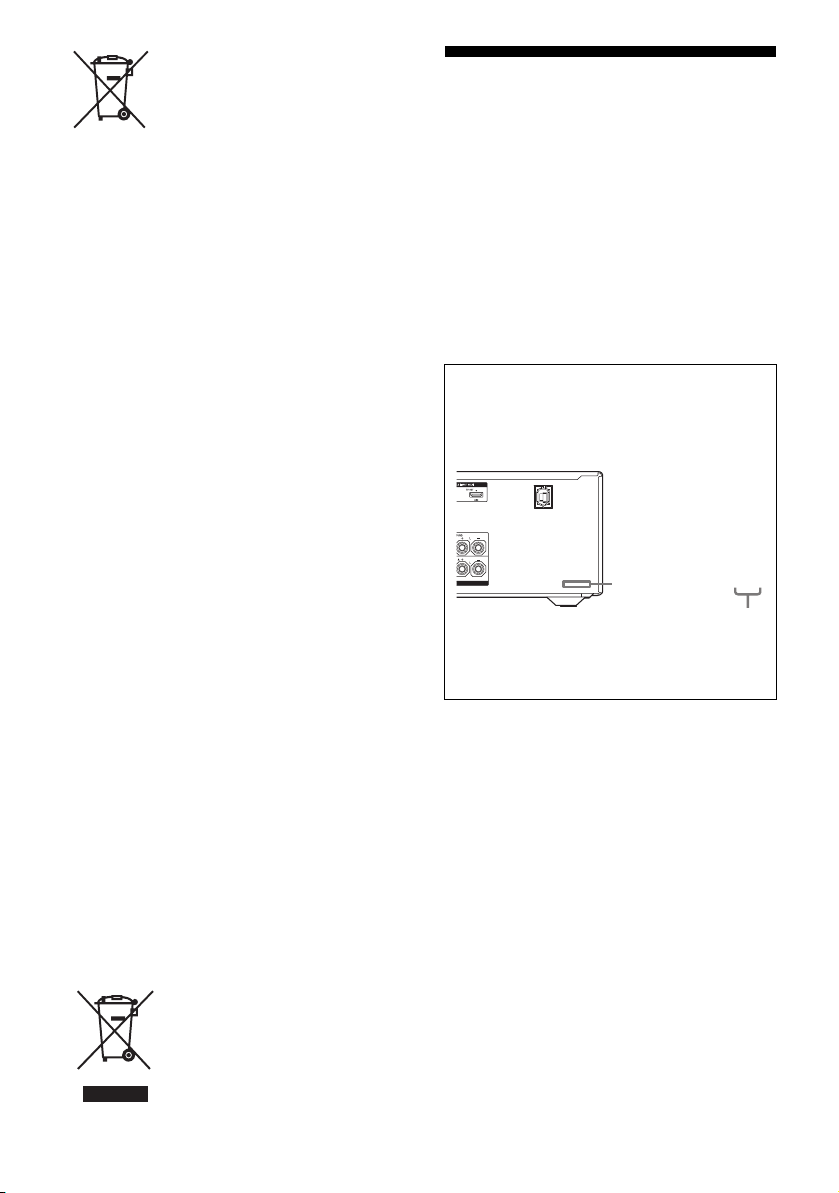
About area codes
The area code of the receiver you purchased is
shown on the lower right portion of the rear panel
(see the illustration below).
4-XXX-XXX-XX (X) AA
Area code
Any differences in operation, according to the area
code, are clearly indicated in the text, for example,
“Models of area code AA only”.
For customers in Australia
Disposal of Old Electrical &
Electronic Equipment
(Applicable in the European
Union and other European
countries with separate
collection systems)
GB
4
Page 5

On copyrights
This receiver incorporates Dolby* Digital and Pro
Logic Surround and the DTS** Digital Surround
System.
* Manufactured under license from Dolby
Laboratories. Dolby, Pro Logic, and the
double-D symbol are trademarks of Dolby
Laboratories.
** Manufactured under license under U.S. Patent
#’s: 5,451,942; 5,956,674; 5,974,380; 5,978,762;
6,226,616; 6,487,535; 7,212,872; 7,333,929;
7,392,195; 7,272,567 & other U.S. and
worldwide patents issued & pending. DTS is a
registered trademark and the DTS logos, Symbol,
DTS-HD and DTS-HD Master Audio are
trademarks of DTS, Inc. © 1996-2008 DTS, Inc.
All Rights Reserved.
“BRAVIA” is a trademark of Sony Corporation.
“PlayStation” is a registered trademark of Sony
Computer Entertainment Inc.
“S-AIR” and its logo are trademarks of Sony
Corporation.
DLNA and DLNA CERTIFIED are trademarks
and/or service marks of the Digital Living Network
Alliance.
This receiver incorporates High-Definition
Multimedia Interface (HDMI
TM
) technology.
HDMI, the HDMI Logo, and High-Definition
Multimedia Interface are trademarks or registered
trademarks of HDMI Licensing LLC in the United
States and other countries.
SIRIUS, XM and all related marks and logos are
trademarks of Sirius XM Radio Inc. and its
subsidiaries. All rights reserved. Service not
available in Alaska and Hawaii.
The font type (Shin Go R) installed in this receiver
is provided by MORISAWA & COMPANY LTD.
These names are the trademarks of MORISAWA &
COMPANY LTD., and the copyright of the font also
belongs to MORISAWA & COMPANY LTD.
iPod is a trademark of Apple Inc., registered in the
U.S. and other countries.
All other trademarks and registered trademarks are
of their respective holders. In this manual, ™ and ®
marks are not specified.
The Bluetooth word mark and logos are owned by
the Bluetooth SIG, Inc. and any use of such marks
by Sony Corporation is under license.
Other trademarks and trade names are those of their
respective owners.
“M-crew Server” is a trademark of Sony
Corporation.
“x.v.Color (x.v.Colour)” and “x.v.Color
(x.v.Colour)” logo are trademarks of Sony
Corporation.
GB
5
Page 6

Table of Contents
About This Manual........................................4
Supplied accessories......................................8
Description and location of parts...................9
Connections
1: Installing the speakers .............................19
2: Connecting the speakers..........................21
3: Connecting the TV ..................................23
4a: Connecting the audio components.........24
4b: Connecting the video components ........26
5: Connecting the antennas (aerials)............35
6: Inserting the wireless transmitter/
transceiver...............................................35
7: Connecting the AC power cord
(mains lead) ............................................36
Preparing the Receiver
Initializing the receiver................................ 37
Selecting the front speaker system ..............37
Calibrating the appropriate speaker settings
automatically (Auto Calibration)............38
Guide to on-screen display operation ..........44
Basic Operations
Playback ......................................................46
Enjoying sound/images from the components
connected to the DIGITAL MEDIA
PORT......................................................48
Using the Sleep Timer .................................52
Recording using the receiver .......................52
Tuner Operations
Listening to FM/AM radio.......................... 53
Presetting FM/AM radio stations
(Preset Tuning)....................................... 55
Using the Radio Data System (RDS).......... 56
(Models of area code CEK, ECE, AU1,
TW2 only)
Listening to Satellite Radio......................... 57
(Models of area code U2, CA2 only)
Connecting the SIRIUS Satellite Radio...... 58
Preparing to listen to the SIRIUS Satellite
Radio...................................................... 58
Selecting a channel of the SIRIUS Satellite
Radio...................................................... 59
Presetting SIRIUS Satellite Radio
channels ................................................. 61
Restricting access to specific channels
(Parental Lock) ...................................... 62
Enjoying Surround Sound
Selecting the sound field............................. 65
Enjoying the surround effect at low volume
levels (NIGHT MODE) ......................... 69
Resetting sound fields to the initial
settings ................................................... 69
“BRAVIA” Sync Features
What is “BRAVIA” Sync?.......................... 70
Preparing for the “BRAVIA” Sync ............. 70
Playing back components with one-touch
operation (One-Touch Play)................... 72
Enjoying the TV sound from the speakers
connected to the receiver
(System Audio Control)......................... 72
Turning off the receiver with the TV
(System Power Off) ............................... 73
Enjoying movies with the optimum sound
field (Theater/Theatre Mode Sync)........ 73
Enjoying the TV sound via an HDMI cable
(Audio Return Channel)......................... 74
GB
6
Page 7

S-AIR Operations
About S-AIR products ................................ 75
Setting up an S-AIR product....................... 76
Enjoying the system’s sound in another
room ....................................................... 80
Changing the channel for better sound
transmission ........................................... 81
Stabilizing S-AIR reception ........................82
Enjoying the S-AIR receiver while the
S-AIR main unit is in standby mode......83
Advanced Operations
Switching between digital and analog audio
(INPUT MODE) .................................... 84
Enjoying the sound/images from other
inputs...................................................... 85
Using a bi-amplifier connection.................. 88
Using the setting menu................................ 89
Auto Calibration menu................................ 90
Speaker Settings menu ................................ 91
Surround Settings menu.............................. 95
EQ Settings menu........................................ 96
Audio Settings menu ................................... 96
Video Settings menu ................................... 97
HDMI Settings menu .................................. 98
System Settings menu ............................... 100
Operating without connecting to a TV...... 101
Using the Remote
Programming the remote........................... 112
Clearing all the contents of the remote’s
memory ................................................ 116
Additional Information
Glossary .................................................... 117
Precautions ................................................ 120
Troubleshooting ........................................ 122
Specifications ............................................ 129
Index.......................................................... 132
GB
7
Page 8
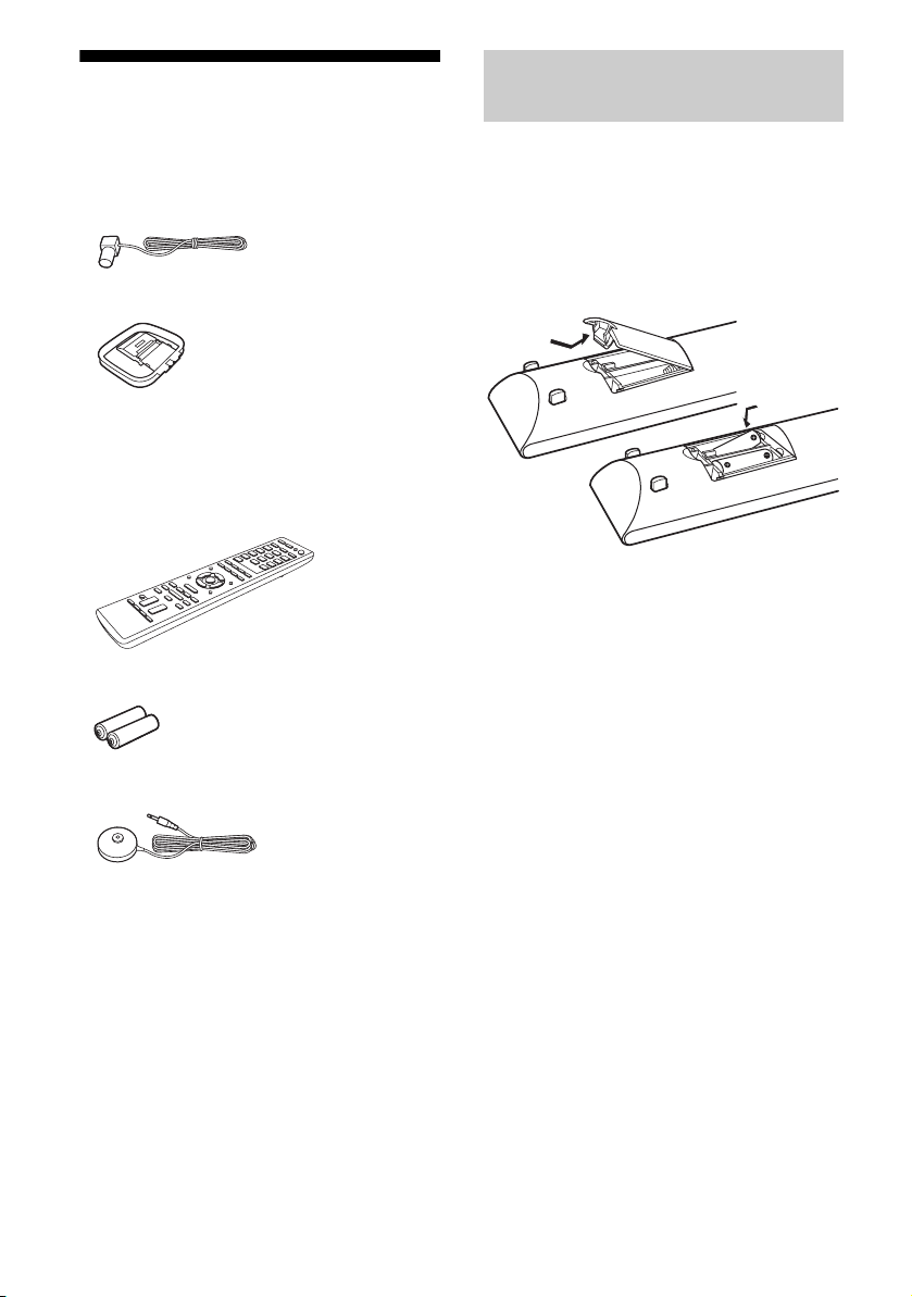
Supplied accessories
• Operating Instructions (this manual)
• Quick Setup Guide
• GUI Menu List
• FM wire antenna (aerial) (1)
• AM loop antenna (aerial) (1)
• Remote commander (1)
– RM-AAP051 (Models of area code U2,
CA2 only)
– RM-AAP052 (Models of area code ECE,
CEK, AU1, TW2 only)
• R6 (size-AA) batteries (2)
• Optimizer microphone (ECM-AC2) (1)
Inserting batteries into the
remote
Insert two R6 (size-AA) batteries in the
RM-AAP051 (Models of area code U2, CA2
only) or RM-AAP052 (Models of area code
CEK, ECE, AU1, TW2 only) Remote
Commander.
Observe the correct polarity when installing
batteries.
Notes
• Do not leave the remote in an extremely hot or
humid place.
• Do not use a new battery with old ones.
• Do not mix manganese batteries and other kinds of
batteries.
• Do not expose the remote sensor to direct sunlight
or lighting apparatuses. Doing so may cause a
malfunction.
• If you do not intend to use the remote for an
extended period of time, remove the batteries to
avoid possible damage from battery leakage and
corrosion.
• When you replace the batteries, the programmed
remote codes may be cleared. If this happens,
program the remote codes again (page 112).
• When the remote no longer operates the receiver,
replace all the batteries with new ones.
GB
8
Page 9
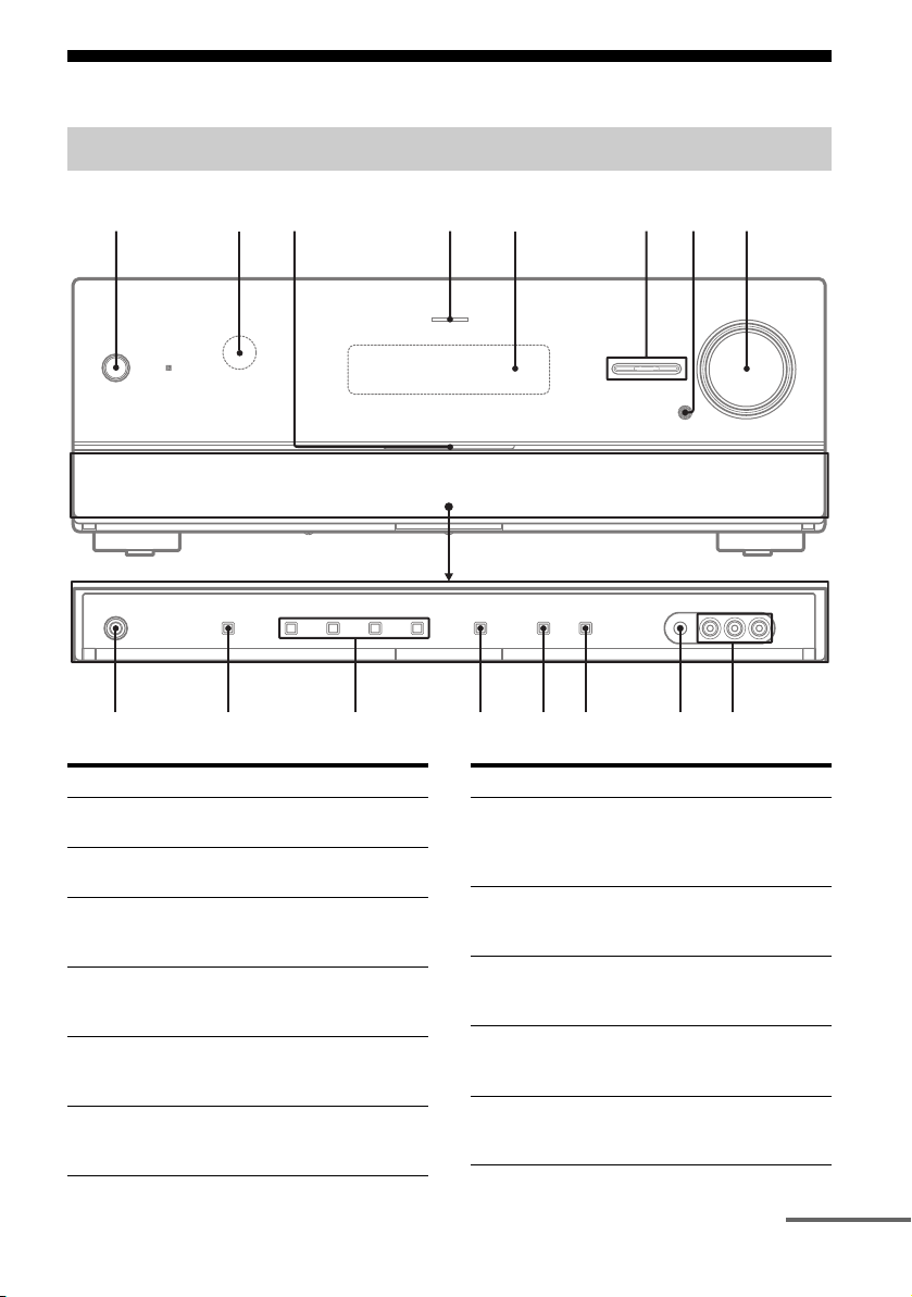
Description and location of parts
90q
q
q
q
q
q
Front panel
1
h
23 4 568
g
f
Name and function
A ?/1 (on/standby)
Turns the receiver on or off (page 37, 55, 69).
B Remote sensor
Receives signals from remote commander.
C White indicator
Lights up when the receiver is on.
Lights off when the receiver is off.
D MULTI CHANNEL DECODING indicator
Lights up when multi channel audio signals are
decoded (page 124).
E Display
Displays the current status of the selected
component or a list of selectable items (page 11).
F INPUT SELECTOR +/–
Selects the input source to playback (page 46,
52, 84).
7
a
s
d
Name and function
G MUTING
Turns off the sound temporarily.
Press MUTING again to restore the sound (page
47, 122).
H MASTER VOLUME
Adjusts the volume level of all speakers at the
same time (page 46, 122).
I VIDEO 2 IN jacks
Connects to a portable audio/video component
such as a camcorder or video game (page 33).
J AUTO CAL MIC jack
Connects to the supplied optimizer microphone
for the Auto Calibration function (page 39).
K DISPLAY
Selects the information displayed on the display
(page 47, 128).
continued
GB
9
Page 10

Name and function
L DIMMER
Adjusts the brightness of the display (page 111).
M INPUT MODE
Selects the input mode when the same
components are connected to both digital and
analog jacks (page 84).
N 2CH/A.DIRECT, A.F.D., MOVIE, MUSIC
Selects a sound field (page 65, 66).
O SPEAKERS
Selects the front speaker system (page 37).
P PHONES jack
Connects to headphones (page 122).
10
GB
Page 11
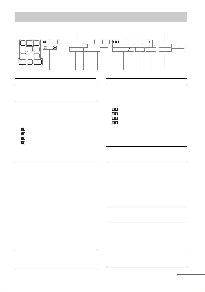
About the indicators on the display
q
12 3 4 5 6897
PL ll
x z
LH SW RH
L
C
SL SRS
SB
SB RSB L
R
ANALOG HDMI COAX OPT
LF E
D.RANGE
k
Indicator and explanation
SW
A
Lights up when the audio signal is output from
the SUBWOOFER jack.
B Dolby Pro Logic indicators
Lights up one of the respective indicators when
the receiver performs Dolby Pro Logic
processing. This matrix surround decoding
technology can enhance input signals.
PL
PL II
PL IIx
PL IIz
Note
These indicators may not light up depending on
the speaker pattern setting.
C Input indicators
Light up to indicate the current input.
ANALOG
Lights up when
– INPUT MODE is set to “ANALOG”.
– Sound Field is set to “Analog Direct”.
– No digital signals are detected.
HDMI
The receiver recognizes a component connected
via an HDMI IN jack.
COAX
When INPUT MODE is set to “AUTO” and the
source signal is a digital signal being input
through the COAXIAL jack (page 84).
OPT
When INPUT MODE is set to “AUTO” and the
source signal is a digital signal being input
through the OPTICAL jack (page 84).
D ARC
Lights up when TV input is selected and the
Audio Return Channel (ARC) signals are
detected (page 100).
Dolby Pro Logic
Dolby Pro Logic II
Dolby Pro Logic IIx
Dolby Pro Logic IIz
EQ RDS
SIRIUS ST
MEMCAT
ARC
D + EX
DTS – HD
DTS –ES
TrueHD
MSTR
96 24
NEO
HI RES LBR
LPCM
SLEEP
6
S –AIR
BI –AMP
q;qaqsqdqfqh qgqj
Indicator and explanation
E Dolby Digital Surround indicators
Lights up one of the respective indicators when
the receiver is decoding the corresponding
Dolby Digital format signals.
D
D EX
D+
TrueHD
Note
When playing a Dolby Digital format disc, be
sure that you have made digital connections and
that INPUT MODE is set to “AUTO” (page 84).
F NEO:6
Lights up when DTS Neo:6 Cinema/Music
decoder is activated (page 66).
G DTS-HD indicators
Lights up one of the respective indicators when
the receiver is decoding the corresponding
DTS-HD format signals.
DTS-HD MSTR
DTS-HD HI RES
DTS-HD LBR
H S-AIR
Lights up when the S-AIR transmitter (not
supplied) is inserted.
I SP A/SP B/SP A B
Lights up according to the front speaker system
used (page 37).
However, these indicators do not light up if the
speaker output is turned off or if headphones are
connected.
J BI-AMP
Lights up when surround back speakers
selection is set to “BI-AMP” (page 88).
Dolby Digital
Dolby Digital Surround EX
Dolby Digital Plus
Dolby TrueHD
DTS-HD Master Audio
DTS-HD High Resolution
Audio
DTS-HD Low Bit Rate
Audio
SPAB
continued
11
GB
Page 12
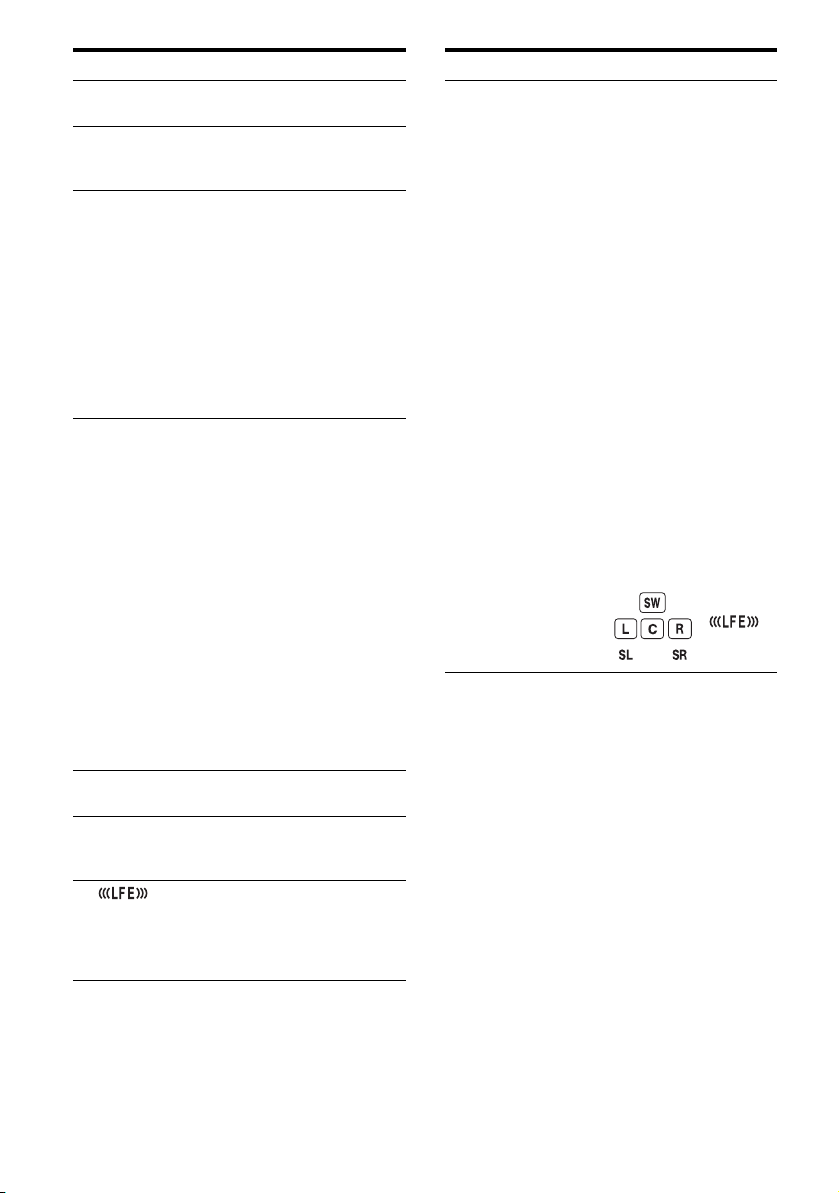
Indicator and explanation
K SLEEP
Lights up when the Sleep Timer is activated.
L LPCM
Lights up when Linear PCM (Pulse Code
Modulation) signals are decoded.
M DTS(-ES) indicators
Lights up one of the respective indicators when
the receiver is decoding the corresponding DTS
format signals.
DTS
DTS-ES
DTS 96/24
Note
When playing a DTS format disc, be sure that
you have made digital connections and that
INPUT MODE is set to “AUTO” (page 84).
N Tuning indicators
Lights up when the receiver tunes in radio
stations, or satellite radio stations.
RDS (Models of area code CEK, ECE,
AU1, TW2 only)
A station that provides RDS services is tuned in.
CAT (Models of area code U2, CA2 only)
The category mode is selected during the
satellite radio operation.
MEM
A memory function, such as Preset Memory
(page 55), etc., is activated.
SIRIUS (Models of area code U2, CA2
only)
The SiriusConnect Home tuner is connected and
“SR” is selected.
ST
Stereo broadcast
O EQ
Lights up when the equalizer is activated.
P D.RANGE
Lights up when dynamic range compression is
activated (page 94).
Q
Lights up when the disc being played back
contains an LFE (Low Frequency Effect)
channel and the LFE channel signal is actually
being reproduced.
DTS
DTS-ES
DTS 96 kHz/24 bit
Indicator and explanation
R Playback channel indicators
The letters (L, C, R, etc.) indicate the channels
being played back. The boxes around the letters
vary to show how the receiver downmixes or
upmixes the source sound (based on the speaker
pattern settings).
LH
RH
L
R
C
SL
SR
S
SBL
SBR
SB
Front Left High
Front Right High
Front Left
Front Right
Center (monaural)
Surround Left
Surround Right
Surround (monaural or the
surround components
obtained by Pro Logic
processing)
Surround Back Left
Surround Back Right
Surround Back (the
surround back components
obtained by 6.1 channel
decoding)
Example:
Speaker pattern: 3/0.1
Recording format: 3/2.1
Sound Field: A.F.D. AUTO
12
GB
Page 13
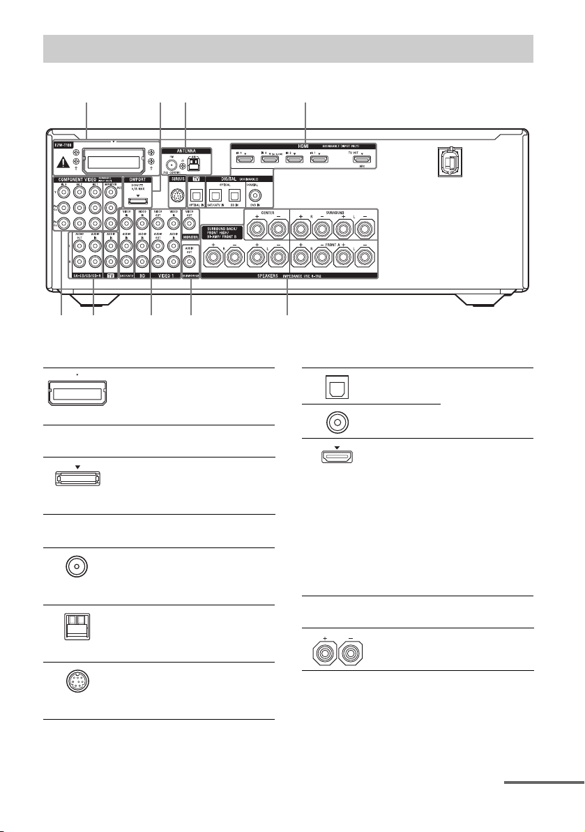
Rear panel
1 2 43
8 76 6 5
A S-AIR section
EZW-T100
slot
B DMPORT section
DMPORT
jack
C ANTENNA section
FM
ANTENNA
jack
AM
ANTENNA
terminals
SIRIUS jack
(Models of
area code U2,
CA2 only)
Connects to a
wireless transmitter
(not supplied)
(page 35).
Connects to a Sony
DIGITAL MEDIA
PORT adapter
(page 24).
Connects to the
supplied FM wire
antenna (aerial)
(page 35).
Connects to the
supplied AM loop
antenna (aerial)
(page 35).
Connects to a
SiriusConnect Home
tuner (not supplied)
(page 58).
D DIGITAL INPUT/OUTPUT section
OPTICAL
IN jacks
COAXIAL
IN jack
HDMI IN/
OUT* jacks
Connects to a
Blu-ray disc player,
etc. (page 23, 30,
31, 32).
Connects to a DVD
player, satellite
tuner, Blu-ray disc
player, etc. The
image is output to a
TV or a projector
while the sound can
be output from a TV
or/and speakers
connected to this
receiver (page 23,
27).
E SPEAKERS section
Connects to
speakers (page 21).
continued
13
GB
Page 14
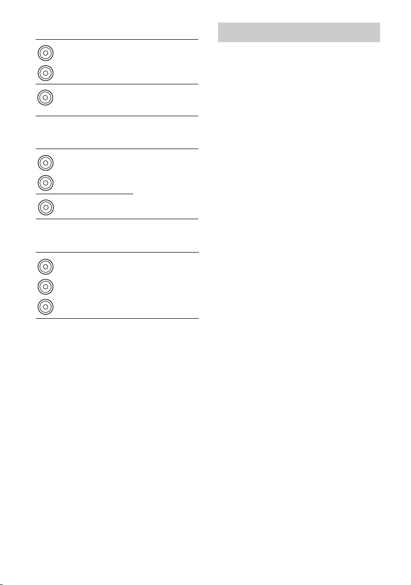
F AUDIO INPUT/OUTPUT section
White (L)
Red (R)
Black
AUDIO IN/
OUT jacks
AUDIO OUT
jack
Connects to a Super
Audio CD player,
etc. (page 23, 24).
Connects to a
subwoofer
(page 21).
G VIDEO/AUDIO INPUT/OUTPUT
section
White (L)
Red (R)
Yellow
AUDIO IN/
OUT jacks
VIDEO IN/
OUT* jacks
Connects to a VCR,
Blu-ray disc player,
etc. (page 30, 32,
33).
H COMPONENT VIDEO INPUT/
OUTPUT section
Green
(Y)
Blue
(P
B/CB)
Red
R/CR)
(P
Y, PB/CB,
P
R/CR IN/
OUT* jacks
Connects to a
Blu-ray disc player,
TV, satellite tuner,
etc. (page 23, 30, 31,
32).
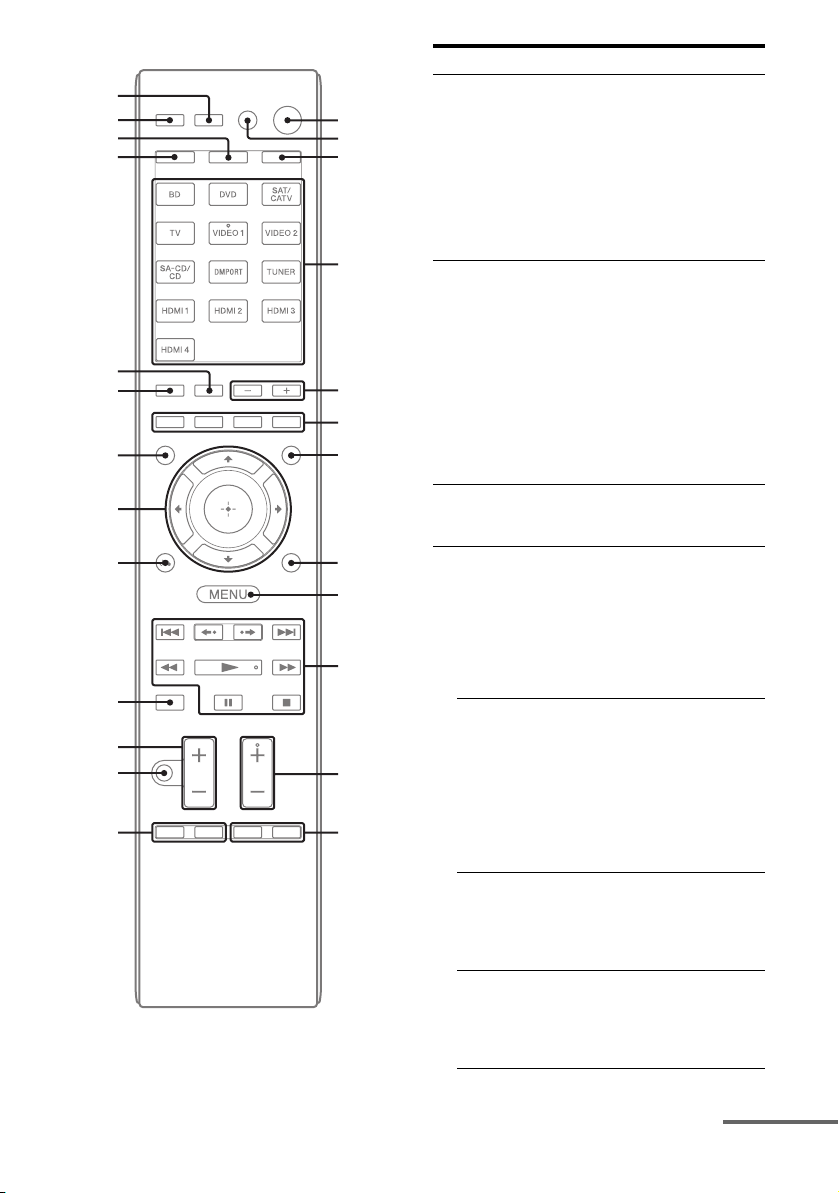
Remote commander
You can use the supplied remote to operate the
receiver and to control the Sony audio/video
components that the remote is assigned to
operate.
You can also program the remote to control
non-Sony audio/video components. For
details, see “Programming the remote”
(page 112).
• RM-AAP051 (Models of area
code U2, CA2 only)
• RM-AAP052 (Models of area
code CEK, ECE, AU1, TW2
only)
* You can watch the selected input image when you
connect the MONITOR OUT or HDMI TV OUT
jack to a TV (page 23).
GB
14
Page 15
wg
wf
wd
ws
wa
w;
ql
qk
qj
qh
qg
qf
qd
1
2
3
4
5
6
7
8
9
0
qa
qs
Name and function
?/1 (on/standby)
A
Turns the receiver on or sets it to the standby
mode.
To turn off all components, press ?/1 and
AV ?/1 (B) at the same time (SYSTEM
STANDBY).
Saving the power in standby mode
When “Ctrl for HDMI” is set to “OFF” (page
70) and “S-AIR Stby” is set to “OFF” (page 83).
a)
AV ?/1
B
Turns on or off the audio/video components that
the remote is programmed to operate.
To turn the TV on or off, press TV (W) and
then press AV ?/1.
If you press ?/1 (A) at the same time, it will
turn off the receiver and other components
(SYSTEM STANDBY).
Note
The function of the AV ?/1 switch changes
automatically each time you press the input
buttons (D).
C AMP
The button lights up and activates the receiver
operation (page 101).
D Input buttons (VIDEO 1
Selects the component you want to use. When
you press any of the input buttons, the receiver
turns on. The buttons are initial assigned to
control Sony components. You can program the
remote to control non-Sony components
following the steps in “Programming the
remote” on page 112.
Numeric buttons
Press SHIFT (V), then press numeric buttons
to
– preset/tune to preset stations.
– select track numbers. Press 0/10 to select track
– select channel numbers.
Press TV (W), then press the numeric buttons
to select the TV channels.
-/--
Press SHIFT (V), then press -/-- to select the
channel entry mode, either one or two digit.
To select the channel entry mode of the TV,
press TV (W) and then press -/--.
>10
Press SHIFT (V), then press >10 to select track
numbers over 10. You can also select the
channel numbers of the DIGITAL CATV
terminal.
(on/standby)
number 10.
a)
a)
b)
)
a)
(number 5b))
.
continued
15
GB
Page 16
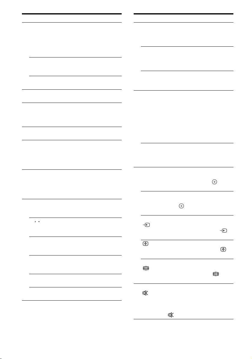
Name and function
a)
ENTER
Press SHIFT (V), then press ENTER to enter
the value after selecting a channel, disc or track
using the numeric buttons.
To enter the value of Sony TV, press TV (W)
and then press ENTER.
MEMORY
Press SHIFT (V), then press MEMORY to
store a station during tuner operation.
a)
/
(Text) (RM-AAP052 only)
Press TV (W), then press
E SOUND FIELD +/–
Selects a sound field (page 65).
F Color buttons
a)
Displays an operation guide on the TV screen
when the color buttons are available. Follow the
operation guide to perform a selected operation.
G GUI MODE
Displays the GUI menu on the TV screen.
H TOOLS/OPTIONS
Displays and selects items from the option
menus.
To display the options of Sony TV, press TV
(W) and then press TOOLS/OPTIONS.
I MENU, HOME
a)
Displays the menu to operate the audio/video
components.
To display the menus of Sony TV, press TV
(W) and then press HOME.
J ./>
a),
m/Ma), N
Skip, backward/forward, play, pause, stop
operation.
a)
<
<
/
Replay the previous scene or fast forward the
current scene.
CATEGORY +/– (RM-AAP051 only)
Selects a category for satellite tuner (page 60,
110).
CATEGORY MODE
Selects the category mode for satellite tuner
(page 59, 110).
TUNING +/–
a)
Scans a station.
D.TUNING
Enters direct tuning mode (page 54, 109).
/ to display text.
a)
a)b)
, Xa), x
b)
(RM-AAP051 only)
Name and function
K TV CH +b)/–a) (RM-AAP051 only)
PROG +
Press TV (W), then press TV CH +/– or
PROG +/– to select preset TV channels.
PRESET +
Selects
– preset stations.
– preset channels.
c
In text mode: Press TV (W), then press
to select the next or previous page.
L F1
Press BD or DVD (D), then press F1 or F2 to
select a component.
• DVD/HDD COMBO
• DVD/VCR COMBO
SLEEP
Activates the Sleep Timer function and the
duration which the receiver turns off
automatically (page 52).
M BD/DVD TOP MENU
Displays the menu or on-screen guide on the TV
screen. Then, use V/v/B/b (R) and (R) to
perform menu operations.
BD/DVD MENU
a)
Displays the menu on the TV screen. Then, use
V/v/B/b (R) and (R) to perform menu
operations.
TV INPUT
Press TV (W), then press TV INPUT or to
select the input signal (TV input or video input).
In text mode: Press TV (W), then press to
hold the current page.
WIDE
Press TV (W), then press WIDE or
repeatedly to select the wide picture mode.
N MUTING
Activates the muting function. Press the button
again to restore the sound. To activate the TV’s
muting function, press TV (W) and then press
MUTING or .
b)/–a)
(RM-AAP052 only)
b)/–a)
b)
/C (RM-AAP052 only)
a)
a)
, F2
F1: HDD
F2: DVD disc, Blu-ray disc
F1: DVD disc, Blu-ray disc
F2: VHS
a)
a)
a)
(RM-AAP051 only)
a)
(Input select) (RM-AAP052 only)
a)
(Text hold) (RM-AAP052 only)
a)
(RM-AAP051 only)
a)
(Wide mode) (RM-AAP052 only)
a)
(RM-AAP051 only)
a)
(RM-AAP052 only)
c/C
16
GB
Page 17
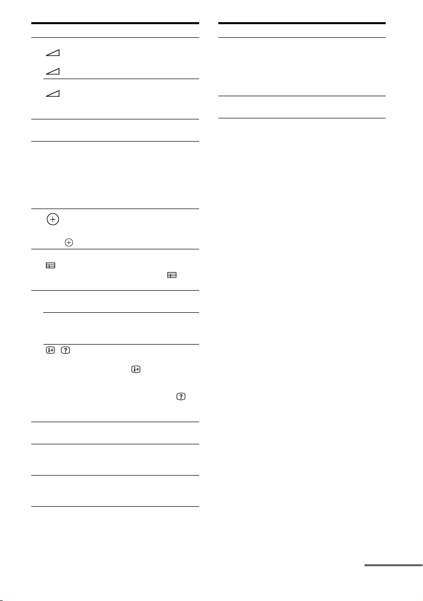
Name and function
O TV VOL +/–a) (RM-AAP051 only)
P DISC SKIP
Q RETURN/EXIT O
R
S GUIDE
T DISPLAY
U NIGHT MODE
Activates the Night Mode function (page 69).
V SHIFT
The button lights up and activates the buttons
with pink printing.
W TV
a)
(RM-AAP052 only)
+/–
Press TV (W), then press TV VOL +/– or
+/– to adjust the TV volume level.
a)
MASTER VOL +/–
a)
+/–
(RM-AAP052 only)
(RM-AAP051 only)
Adjust the volume level of all speakers at the
same time.
a)
Skips disc when using a multi-disc changer.
a)
Returns to the previous menu or exits the menu
while the menu or on-screen guide is displayed
on the TV screen.
To return to the previous menu of Sony TV,
press TV (W) and then press RETURN/EXIT
O.
a)
,
V/v/B/b
a)
Press V/v/B/b to select the menu items, then
press to enter the selection.
a)
(RM-AAP051 only)
a)
(Guide) (RM-AAP052 only)
Press TV (W), then press GUIDE or to
display the on-screen program guide.
a)
Views information on the display.
a)
DISPLAY
(RM-AAP051 only)
Press TV (W), then press DISPLAY to display
information of TV.
, (Info, Text reveal) (RM-AAP052
only)
Press TV (W), then press to display
information such as current channel number and
screen mode.
In text mode: Press TV (W), then press to
reveal hidden information (e.g. answers to a
quiz).
The button light up and activates the buttons
with yellow printing.
Name and function
X THEATER (RM-AAP051 only)
THEATRE (RM-AAP052 only)
Sets the optimal picture settings automatically
for watching movies when you connect a Sony
TV that is compatible with the THEATER or
THEATRE button function (page 73).
Y RM SET UP
Set up the remote.
a)
See the table on page 18 for information on the
buttons that you can use to control each
component.
b)
The following buttons have tactile dots. Use the
tactile dots as reference when operating the
receiver.
– number 5, VIDEO 1
– N, CATEGORY MODE (RM-AAP051 only)
– PRESET +, TV CH + (RM-AAP051 only),
PROG + (RM-AAP052 only),
c
(RM-AAP052 only)
Notes
• Some functions explained in this section may not
work depending on the model.
• The above explanation is intended to serve as an
example only. Therefore, depending on the
component, the above operation may not be
possible or may operate differently than described.
continued
17
GB
Page 18
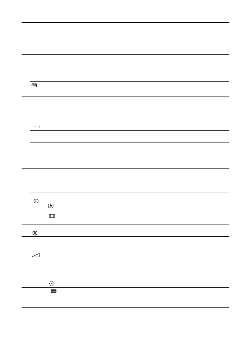
To control other Sony components
Name
B AV ?/1
D Numeric
buttons
-/--, >10
ENTER
*2
(Text)
F Color buttons
H TOOLS/
OPTIONS
MENU, HOME
I
J ./>
<
<
/
m/TUNING –,
M/TUNING +
N, X, x
K PRESET +/–,
TV CH +/–*1,
PROG +/–
*2
L F1, F2
M BD/DVD TOP
MENU, BD/
DVD MENU
TV INPUT*1,
*2
(Input
select), *2
(Text hold),
WIDE*1, *2
(Wide mode)
N
O
MUTING
MASTER
,
*2
*1
VOL +/–*1, TV
VOL +/–*1,
*2
+/–
DISC SKIP
P
Q RETURN/
EXIT O
V/v/B/b,
R
GUIDE*1, *2
S
(Guide)
DISPLAY
T
*1
RM-AAP051 only.
*2
RM-AAP052 only.
*3
DVD player only.
*4
LD player only.
GB
18
TV VCR DVD
zz z z z z z z z z z z
zz z z z z z z z z z z z z
zz z z z z z z z z z
zz z z z z z*4zz zzz
zz
zz*3zz z
zzzzz zz
zz z z z z z z z z
zz z z z z z z z*5zz z
zzzzz z z
zz z z z z z z z z z z
zz z z z z z z z z z z
zz z z z z*4zzz
z
z
z
zzzzzzzzz z
zz z z z z z z z z
zz*3zzz z z
zz z z z z z z z z
Blu-ray
HDD
player,
DVD/
VCR
combo
disc
player
Recorder
PSX Video
zz
zz z
zz z
CD
player,
LD
player
*6
*5
Deck B only.
*6
Video CD only.
*7
m/M only.
Digital
CATV
terminal
DSS*1Digital
*1
terrestrial
receiver
satellite/
Tape
DAT
CD
player,
MD
deck
DIGITAL
MEDIA
PORT
device
*7
deck
deck
A/B
*2
z
Page 19
Connections
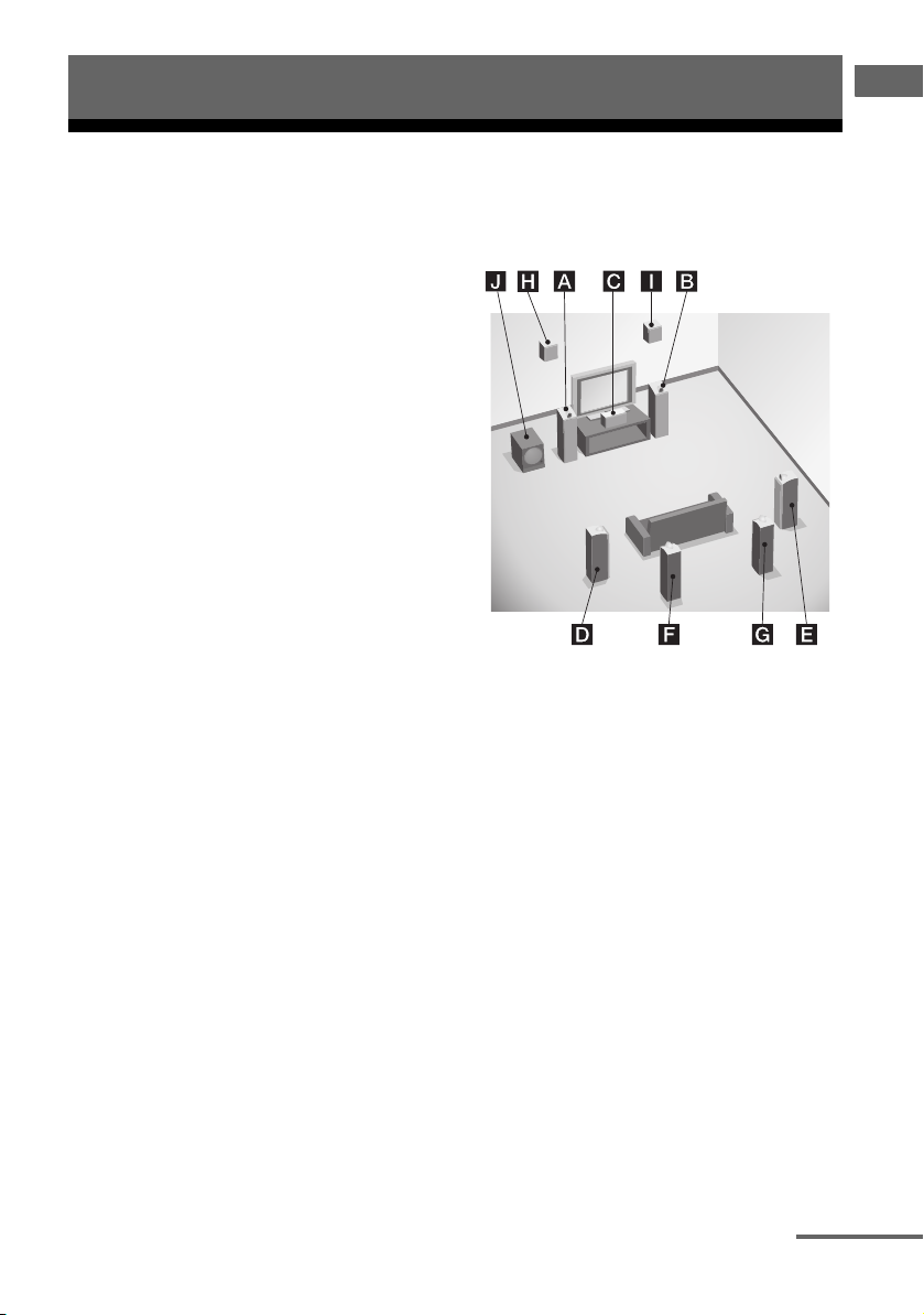
1: Installing the speakers
Connections
This receiver allows you to use a 7.1 channel
system (7 speakers and one subwoofer).
To fully enjoy theater-like multi channel
surround sound requires five speakers (two
front speakers, a center speaker, and two
surround speakers) and a subwoofer (5.1
channel).
You can enjoy high fidelity reproduction of
DVD software recorded sound in the Surround
EX format if you connect additional one
surround back speaker (6.1 channel) or two
surround back speakers (7.1 channel).
You can enjoy vertical sound effects if you
connect additional two front high speakers
(7.1 channel) in PLIIz mode (page 66).
Example of speaker system
configuration
AFront speaker (Left)
BFront speaker (Right)
CCenter speaker
DSurround speaker (Left)
ESurround speaker (Right)
FSurround back speaker (Left)*
GSurround back speaker (Right)*
HFront high speaker (Left)*
IFront high speaker (Right)*
JSubwoofer
* You cannot use the surround back speakers
and the front high speakers simultaneously.
continued
19
GB
Page 20
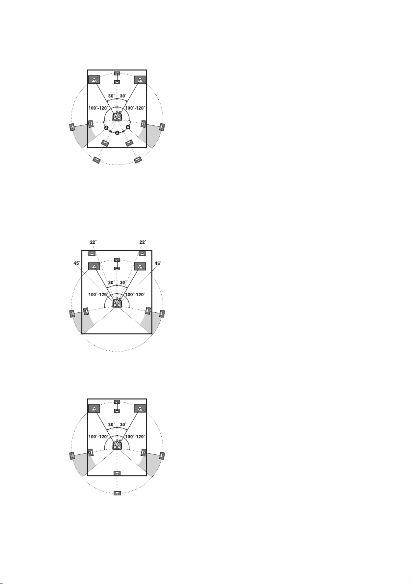
Tips
• When you connect a 7.1 channel speaker system
with two surround back speakers, all angle A
should be the same.
• When you connect a 7.1 channel speaker system
with two front high speakers, place the front high
speakers
– at an angle between 22° to 45°.
– at least 3.3 feet (1 meter) directly above the front
speakers.
• When you connect a 6.1 channel speaker system,
place the surround back speaker behind the
listening position.
• Since the subwoofer does not emit highly
directional signals, you can place it wherever you
want.
GB
20
Page 21
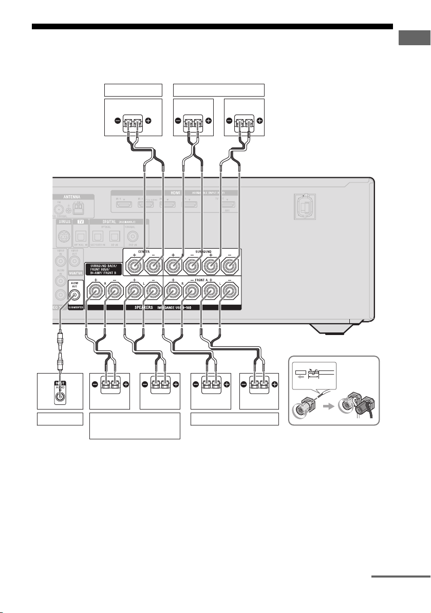
2: Connecting the speakers
Before connecting cords, be sure to disconnect the AC power cord (mains lead).
Connections
A
Subwoofer
Center speaker
Right
b)
Surround back/Front high/
Bi-amplifier/Front B
speaker
B
Surround speaker
Right Left
B
B
B
13/32"
(10 mm)
Left
Front A speaker
a)
LeftRight
A Monaural audio cord (not supplied)
B Speaker cord (not supplied)
continued
21
GB
Page 22
a)
Notes on the SPEAKERS SURROUND BACK/
FRONT HIGH/BI-AMP/FRONT B terminals
connection.
– If you connect only one surround back speaker,
connect it to L of this terminals.
– If you are not using surround back speaker or
front high speakers, and you have an additional
front speaker system, connect the additional
front speaker system to this terminals.
Set “SB Assign” to “Speaker B” in the Speaker
Settings menu (page 91).
You can select the front speaker system you
want using the SPEAKERS button on the
receiver (page 37).
– If you are not using surround back speaker or
front high speakers, you can connect the front
speakers to this terminals using bi-amplifier
connection (page 22).
Set “SB Assign” to “BI-AMP” in the Speaker
Settings menu (page 91).
b)
When you connect a subwoofer with an auto
standby function, turn off the function when
watching movies. If the auto standby function is
set to on, it turns to standby mode automatically
based on the level of the input signal to a
subwoofer, then sound may not be output.
Notes
• Before connecting the AC power cord (mains
lead), make sure that metallic wires of the speaker
cords are not touching each other between the
SPEAKERS terminals.
• After you have install and connect your speaker, be
sure to select the speaker pattern from the Speaker
Settings menu (page 91).
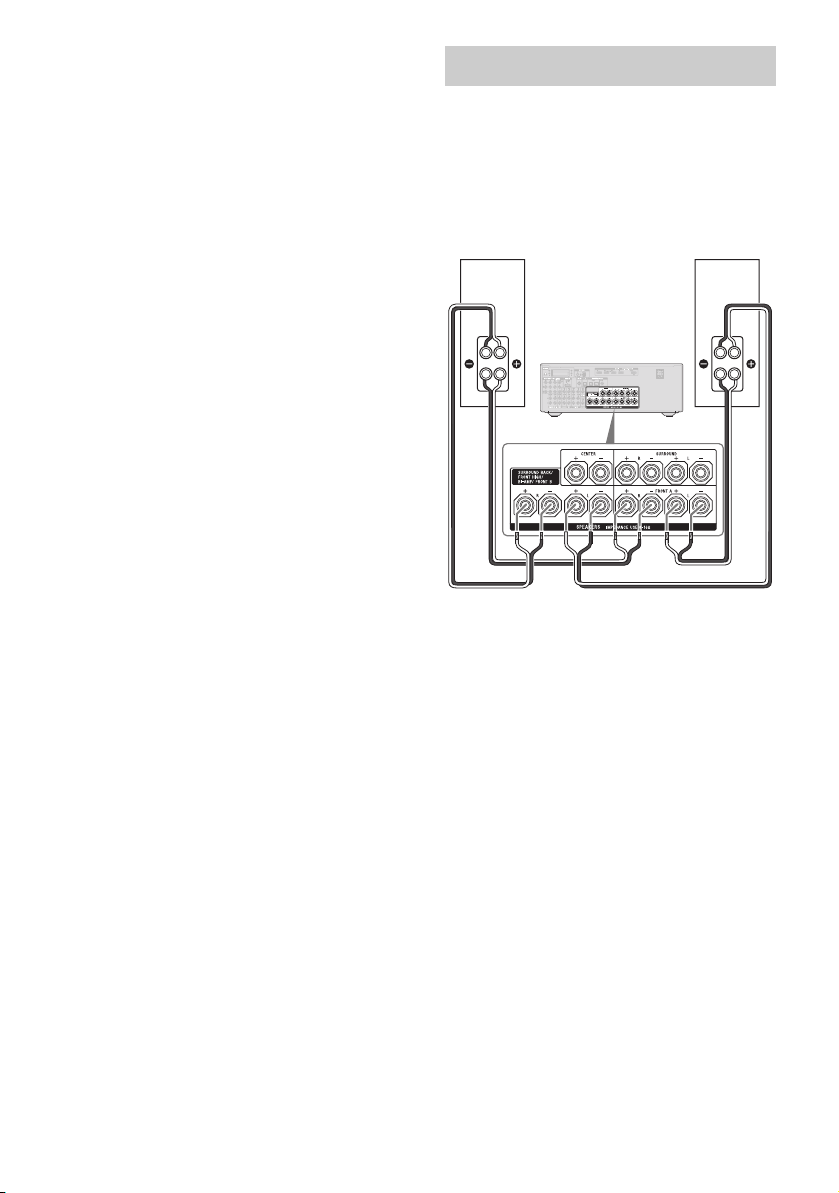
Bi-amplifier connection
If you are not using surround back speakers or
front high speakers, you can connect the front
speakers to the SPEAKERS SURROUND
BACK/FRONT HIGH/BI-AMP/FRONT B
terminals using a bi-amplifier connection.
Front speaker
(Right)
Hi
Lo
Connect the jacks on the Lo (or Hi) side of the
front speakers to the SPEAKERS FRONT A
terminals, and connect the jacks on the Hi (or
Lo) side of the front speakers to the
SPEAKERS SURROUND BACK/FRONT
HIGH/BI-AMP/FRONT B terminals.
Make sure that metal fittings of Hi/Lo attached
to the speakers have been removed from the
speakers. Not doing so may cause a
malfunction of the receiver.
After you have made the bi-amplifier
connection, set “SB Assign” to “BI-AMP” in
the Speaker Settings menu (page 91).
Front speaker
(Left)
Hi
Lo
22
GB
Page 23
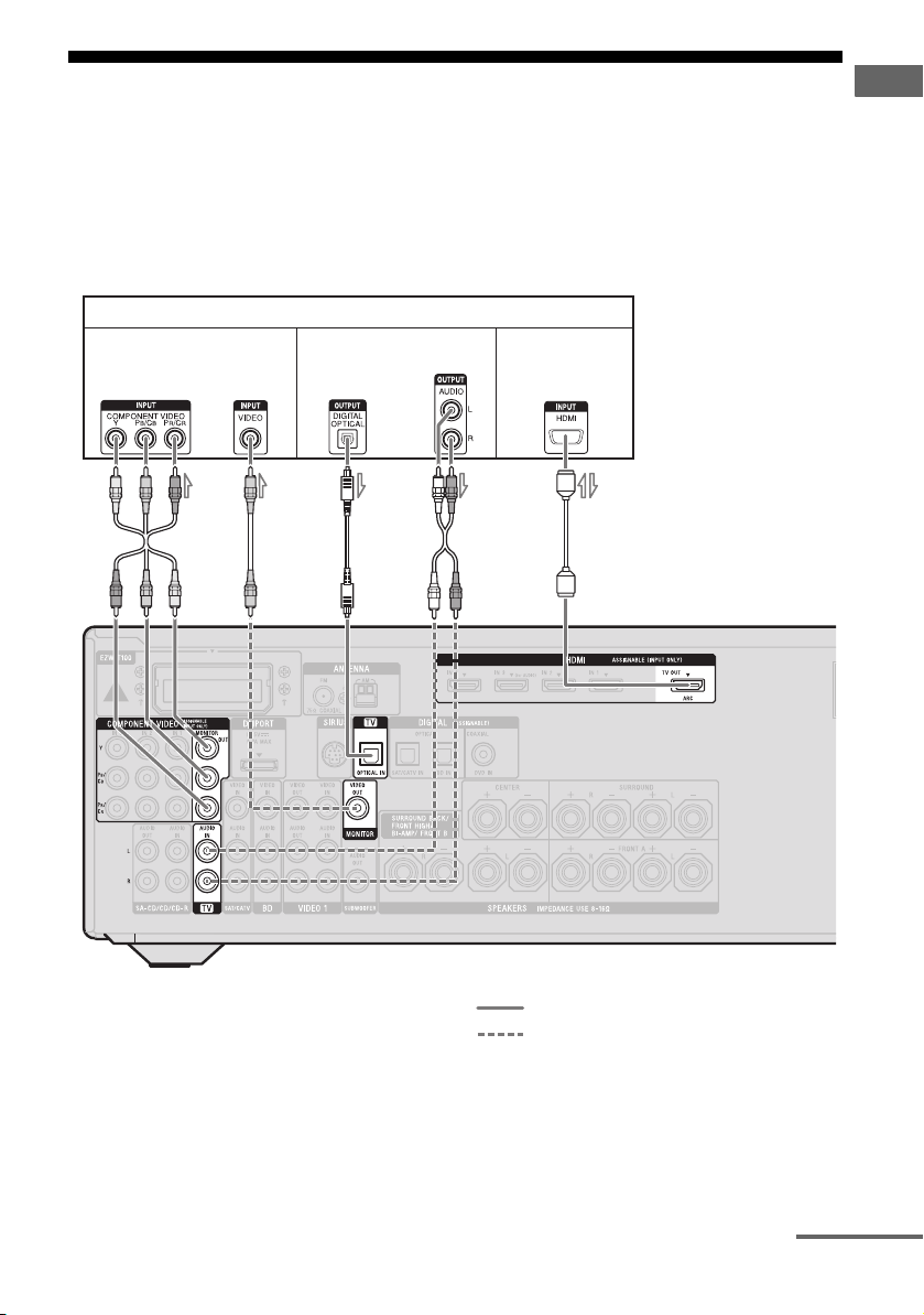
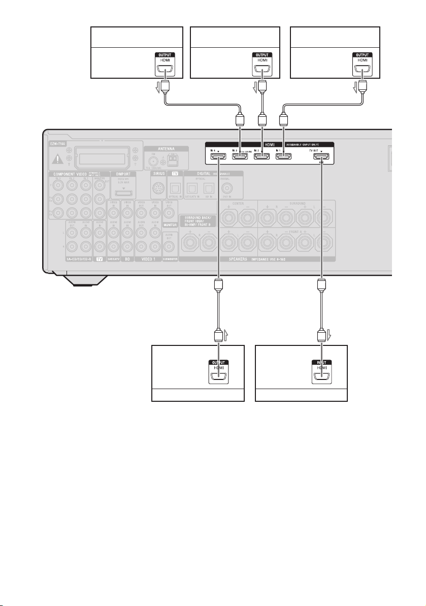
3: Connecting the TV
You can watch the selected input image when
you connect the HDMI TV OUT or
MONITOR OUT jack to a TV. You can
operate this receiver using a GUI (Graphical
User Interface) if you connect HDMI TV OUT
jack to a TV.
TV
Video signals
Audio signals
Connections
It is not necessary to connect all the cables.
Connect audio and video cords according to
the jacks of your components.
Before connecting cords, be sure to disconnect
the AC power cord (mains lead).
Audio/video
signals
ARC
AB
C
a)
D
A Component video cord (not supplied)
B Video cord (not supplied)
a)
E
b)
Recommended connection
Alternative connection
C Optical digital cord (not supplied)
D Audio cord (not supplied)
E HDMI cable (not supplied)
Sony recommends that you use an HDMI-authorized cable or Sony HDMI cable.
continued
23
GB
Page 24
a)
To enjoy TV multi channel surround sound
broadcasting from the speakers connected to the
receiver, connect C or E.
Be sure to turn off the TV’s volume or activate the
TV’s muting function.
b)
If your TV is compatible with the Audio Return
Channel (ARC) function, the TV sound will output
from the speakers connected to the receiver via
HDMI TV OUT connection. In this case, set
“ARC” to “ON” in HDMI Settings menu
(page 100).
Notes
• Be sure to turn on the receiver when the video and
audio signals of a playback component are being
output to a TV via the receiver. If the power supply
of the receiver is not turned on, neither video nor
audio signals will be transmitted.
• Connect image display components such as a TV
monitor or a projector to the HDMI TV OUT or
MONITOR OUT jack on the receiver. You may
not be able to record, even if you connect recording
components.
• Depending on the status of the connection between
the TV and the antenna (aerial), the image on the
TV screen may be distorted. In this case, place the
antenna (aerial) farther away from the receiver.
• When connecting optical digital cords, insert the
plugs straight in until they click into place.
• Do not bend or tie optical digital cords.
Tips
• All the digital audio jacks are compatible with
32 kHz, 44.1 kHz, 48 kHz, and 96 kHz sampling
frequencies.
• The receiver has a video conversion function. For
details, see “Function for conversion of video
signals” (page 34).
• When you connect the audio output jack of the TV
to the TV IN jacks of the receiver to output the TV
sound from the speakers connected to the receiver,
set the sound output jack of the TV to “Fixed” if it
can be switched between either “Fixed” or
“Variable”.
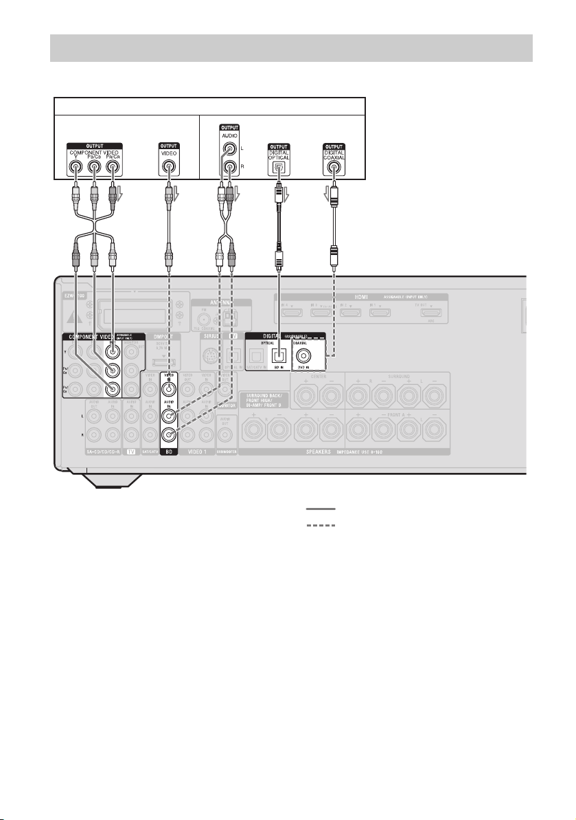
4a: Connecting the audio components
The following illustration shows how to
connect a Super Audio CD player, CD player,
CD recorder and DIGITAL MEDIA PORT
adapter. Before connecting cords, be sure to
disconnect the AC power cord (mains lead).
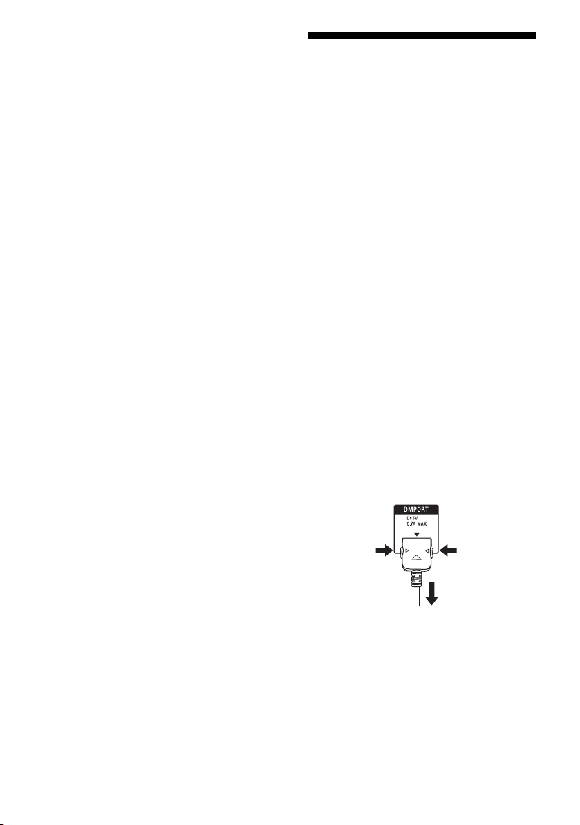
Notes on connecting DIGITAL
MEDIA PORT adapter
• Do not connect or disconnect the DIGITAL
MEDIA PORT adapter while the receiver is
turned on.
• Be sure to make DMPORT connections
firmly, insert the connector straight in.
• As the connector of the DIGITAL MEDIA
PORT adapter is fragile, be sure to handle
with care when placing or moving the
receiver.
• When connecting the DIGITAL MEDIA
PORT adapter, be sure the connector is
inserted with the arrow mark facing towards
the arrow mark on the DMPORT jack.
To detach the DIGITAL MEDIA
PORT adapter from DMPORT
jack
1
2
Press and hold both sides of the connector and
then pull out the connector.
24
GB
Page 25
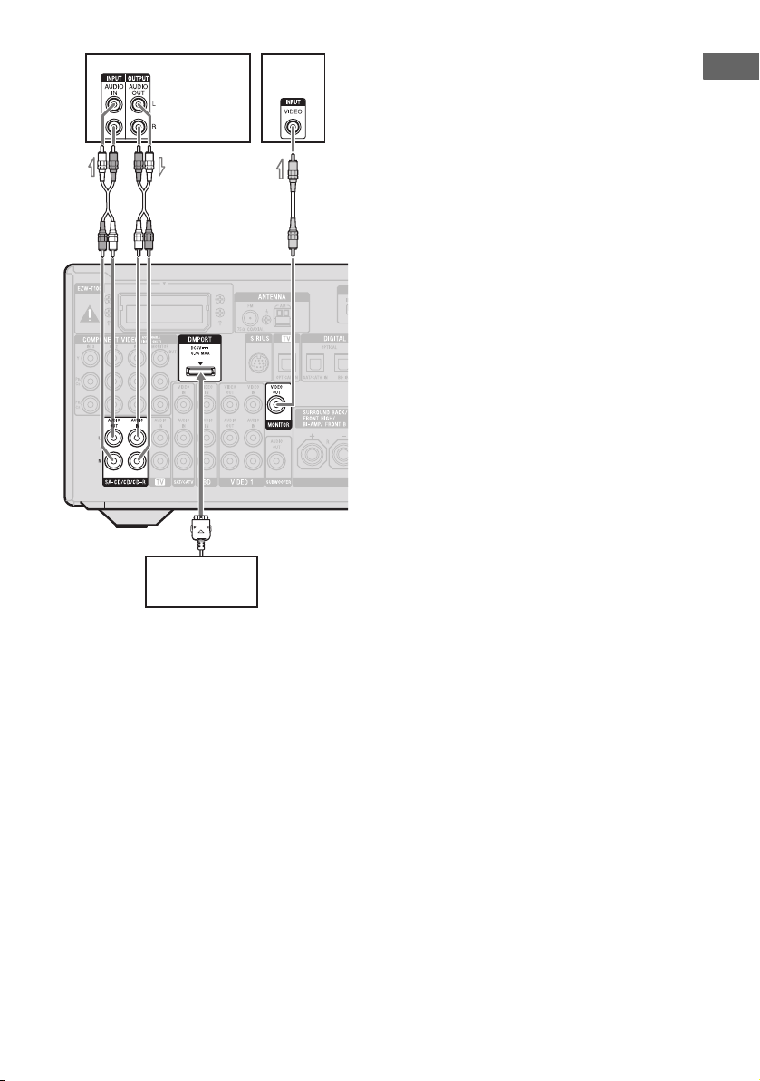
Super Audio
CD player,
CD player,
CD recorder
TV
*
Connections
A
DIGITAL MEDIA
PORT adapter
B
A Audio cord (not supplied)
B Video cord (not supplied)
* You can enjoy the images from the components
connected to the DIGITAL MEDIA PORT adapter
when you connect the TV to the receiver.
25
GB
Page 26
4b: Connecting the video components
Components to be connected
Connect your video components according to
the table below.
Component Page
Blu-ray disc player* 27, 30
DVD player* 27, 31
DVD recorder* 27, 31
Satellite tuner*,
Cable TV tuner*
“PlayStation 3” 27
VCR 33
Camcorder, video game, etc. 33
* We recommend that you connect your video
components via HDMI connection if they have
HDMI jacks.
If you want to connect several
digital components, but cannot
find an unused input
See “Enjoying the sound/images from other
inputs” (page 85).
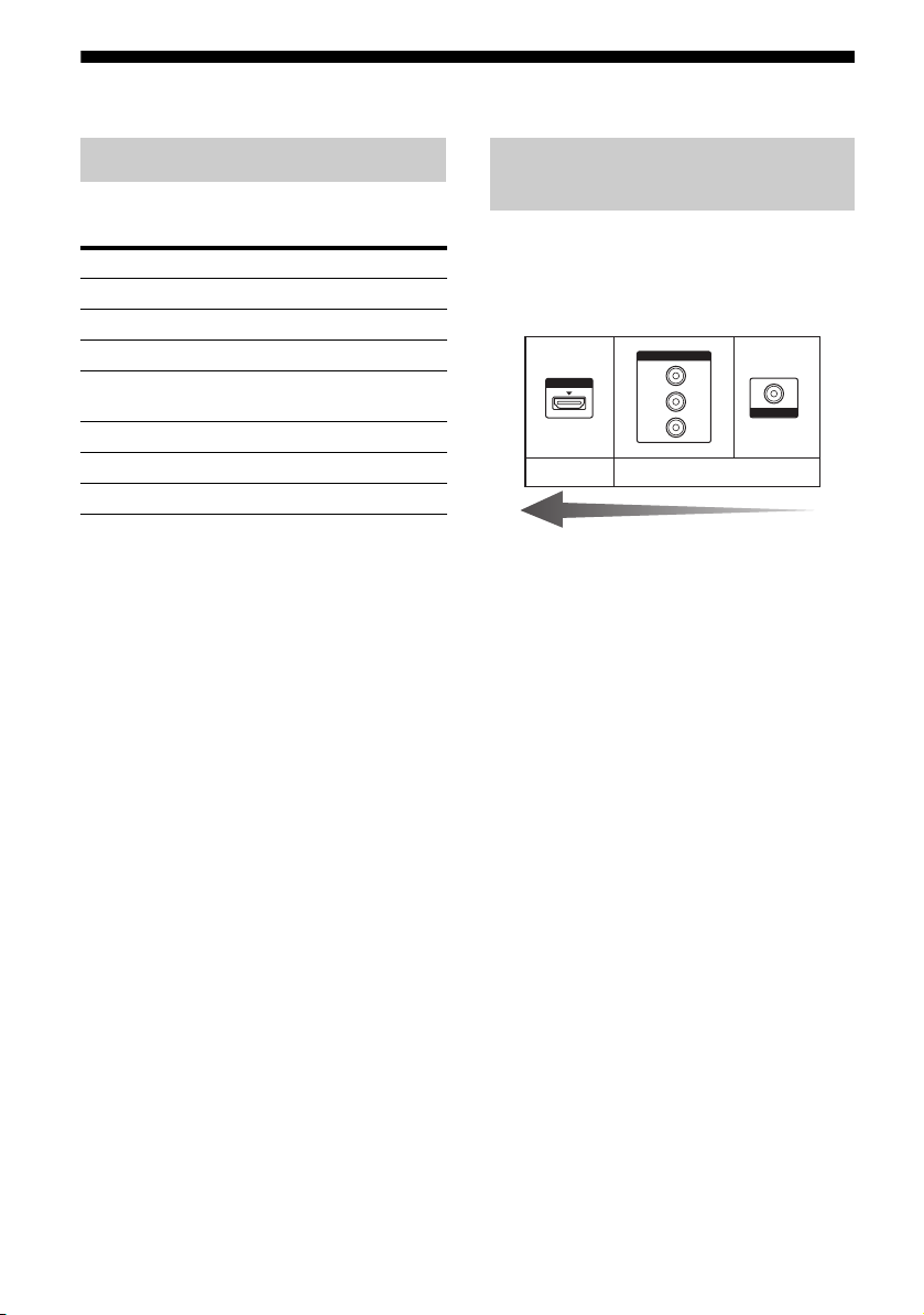
27, 32
Video input/output jacks to be
connected
The image quality depends on the connecting
jack. See the illustration that follows. Select
the connection according to the jacks on your
components.
COMPONENT VIDEO
HDMI
Digital Analog
Converting video signals
This receiver is equipped with a function for
up-converting video signals. For details, see
“Function for conversion of video signals”
(page 34).
Notes
• Before connecting cords, be sure to disconnect the
AC power cord (mains lead).
• It is not necessary to connect all the cords. Connect
according to the availability of jacks on the
connected components.
• Be sure to turn on the receiver when the video and
audio signals of a playback component are being
output to a TV via the receiver. If the power supply
of the receiver is not turned on, neither video nor
audio signals will be transmitted.
• When connecting optical digital cords, insert the
plugs straight in until they click into place.
• Do not bend or tie optical digital cords.
Tip
All the digital audio jacks are compatible with
32 kHz, 44.1 kHz, 48 kHz, and 96 kHz sampling
frequencies.
Y
P
B
/
C
B
P
R
/
C
R
High quality image
VIDEO
26
GB
Page 27

Connecting components with
HDMI jacks
HDMI is the abbreviated name for HighDefinition Multimedia Interface. It is an
interface which transmits video and audio
signals in digital format.
Sony recommends that you connect
components to the receiver using an HDMI
cable.
By connecting Sony “BRAVIA” Synccompatible components using HDMI cables,
operations can be simplified. See ““BRAVIA”
Sync Features” (page 70).
HDMI features
• A digital audio signals transmitted by HDMI
can be output from the speakers connected to
the receiver. This signal supports Dolby
Digital, DTS, and Linear PCM.
• The receiver can receive Multi Linear PCM
(up to 8 channels) with a sampling frequency
of 192 kHz or less with an HDMI
connection.
• Analog video signals input to the VIDEO
jack or COMPONENT VIDEO jacks can be
up-converted as HDMI signals (page 34).
Audio signals are not output from an HDMI
TV OUT jack when the image is converted.
• This receiver supports High Bitrate Audio
(DTS-HD Master Audio, Dolby TrueHD),
Deep Color (Deep Colour), x.v.Color
(x.v.Colour) and 3D transmission.
• This receiver supports the Control for HDMI
function. For details, see ““BRAVIA” Sync
Features” (page 70).
Connections
continued
27
GB
Page 28
Satellite tuner,
Cable TV tuner
Audio/video
signals
DVD player,
DVD recorder
Audio/video
signals
Blu-ray disc player
Audio/video
signals
A
Audio/video
signals
A
A
Audio/video
signals
A
A
ARC
“PlayStation 3”
TV, etc.*
A HDMI cable (not supplied)
Sony recommends that you use an HDMI-authorized cable or Sony HDMI cable.
* For details on the audio connection of TV to the
receiver, see page 23.
Notes
• HDMI 3 input has a better sound quality. When
you need a higher sound quality, connect your
component to the HDMI IN 3 (for AUDIO) jack
and select HDMI 3 as input.
• Be sure to change the initial setting of the HDMI
1–4 input button on the remote so that you can use
the button to control your components. For details,
see “Programming the remote” (page 112).
GB
28
• You can also rename the HDMI input so that it can
be displayed on the receiver’s display. For details,
see “Naming the input (Name Input)” (page 47).
Page 29

Notes on connecting cables
• Use a High Speed HDMI cable. If you use a
Standard HDMI cable, 1080p, Deep Color
(Deep Colour) or 3D images may not be
displayed properly.
• We do not recommend using an HDMI-DVI
conversion cable. When you connect an
HDMI-DVI conversion cable to a DVI-D
component, the sound and/or the image may
not be output. Connect other audio cords or
digital connecting cords, then set “Input
Assign” in the Input Option menu when the
sound is not output correctly.
Notes on HDMI connections
• An audio signal input to the HDMI IN jack
is output from the SPEAKERS jacks, HDMI
TV OUT jack and PHONES jack. It is not
output from any other audio jacks.
• Video signals input to the HDMI IN jack can
only be output from the HDMI TV OUT
jack. The video input signals cannot be
output from the VIDEO OUT jacks or
MONITOR OUT jacks.
• The audio and video signals of HDMI input
are not output from the HDMI TV OUT jack
while the GUI menu is displayed.
• When you want to listen to the sound from
the TV speaker, set “Audio Out” to
“TV+AMP” in the HDMI Settings menu
(page 98). If you cannot play back multi
channel audio source, set to “AMP”.
However, the sound will not output from the
TV speaker.
• DSD signals of Super Audio CD are not
input and output.
• Be sure to turn on the receiver when the
video and audio signals of a playback
component are being output to a TV via the
receiver. If you set “Pass Through” to
“OFF”, video and audio signals will not be
transmitted when the power is turned off.
• Audio signals (sampling frequency, bit
length, etc.) transmitted from an HDMI jack
may be suppressed by the connected
component. Check the setup of the
connected component if the image is poor or
the sound does not come out of a component
connected via the HDMI cable.
• Sound may be interrupted when the
sampling frequency, the number of channels
or audio format of audio output signals from
the playback component is switched.
• When the connected component is not
compatible with copyright protection
technology (HDCP), the image and/or the
sound from the HDMI TV OUT jack may be
distorted or may not be output.
In this case, check the specification of the
connected component.
• You can enjoy High Bitrate Audio (DTS-HD
Master Audio, Dolby TrueHD), multi
channel Linear PCM only with an HDMI
connection.
• Set the image resolution of the playback
component to more than 720p/1080i to
enjoy High Bitrate Audio (DTS-HD Master
Audio, Dolby TrueHD).
• The image resolution of playback
component may need certain settings be
made before you can enjoy multi channel
Linear PCM. Refer to the operating
instructions of the playback component.
• To enjoy 3D images, connect 3D-compatible
TV and video components (Blu-ray disc
player, Blu-ray disc recorder, “PlayStation
3”, etc.) to the receiver using High Speed
HDMI cables, put on 3D glasses, and then
play back a 3D-compatible content.
• Depending on the TV or the video
component, 3D images may not be
displayed. Check the 3D image formats
supported by the receiver (page 131).
• Not every HDMI component supports all
functions that are defined by the specified
HDMI version. For example, components
that support HDMI, version 1.4, may not
support Audio Return Channel (ARC).
• Refer to the operating instructions of each
connected component for details.
Connections
29
GB
Page 30
Connecting a Blu-ray disc player
The following illustration shows how to connect a Blu-ray disc player.
Blu-ray disc player
Video signals Audio signals
A
CB
A Component video cord (not supplied)
B Video cord (not supplied)
C Audio cord (not supplied)
D Optical digital cord (not supplied)
E Coaxial digital cord (not supplied)
Notes
• The initial setting of the COMPONENT VIDEO
IN 1 jacks are Blu-ray disc player. If you want to
connect your Blu-ray disc player to the
COMPONENT VIDEO IN 2 or IN 3 jacks, set
“Input Assign” in the Input Option menu (page 85).
• To input multi channel digital audio from the
Blu-ray disc player, set the digital audio output
setting on the Blu-ray disc player. Refer to the
operating instructions supplied with the Blu-ray
disc player.
DE
*
Recommended connection
Alternative connection
* When you connect a component equipped with an
COAXIAL jack, set “Input Assign” in the Input
Option menu (page 85).
30
GB
Page 31

Connecting a DVD player, DVD recorder
The following illustration shows how to connect a DVD player or DVD recorder.
DVD player, DVD recorder
Video signals Audio signals
AB*C
Connections
A Component video cord (not supplied)
B Optical digital cord (not supplied)
C Coaxial digital cord (not supplied)
Notes
• The initial setting for the DVD input button is as
follows:
– RM-AAP051: DVD player
– RM-AAP052: DVD recorder
To control other components, be sure to change the
initial setting of the DVD input button on the
remote. For details, see “Programming the remote”
(page 112).
• You can also rename the DVD input so that it can
be displayed on the receiver’s display. For details,
see “Naming the input (Name Input)” (page 47).
Recommended connection
Alternative connection
* When you connect a component equipped with an
OPTICAL jack, set “Input Assign” in the Input
Option menu.
• The initial setting of the COMPONENT VIDEO
IN 2 jacks are DVD player or DVD recorder.
If you want to connect your DVD player or DVD
recorder to the COMPONENT VIDEO IN 1 or IN
3 jacks, set “Input Assign” in the Input Option
menu (page 85).
• To input multi channel digital audio from the DVD
player or DVD recorder, set the digital audio
output setting on the DVD player or DVD recorder.
Refer to the operating instructions supplied with
the DVD player or DVD recorder.
31
GB
Page 32

Connecting a satellite tuner, cable TV tuner
The following illustration shows how to connect a satellite tuner or cable TV tuner.
Satellite tuner, Cable TV tuner
Video signals Audio signals
BA
C
A Component video cord (not supplied)
B Video cord (not supplied)
C Audio cord (not supplied)
D Optical digital cord (not supplied)
Note
The initial setting of the COMPONENT VIDEO IN
3 jacks are satellite tuner or cable TV tuner. If you
want to connect your satellite tuner or cable TV
tuner to the COMPONENT VIDEO IN 1 or IN 2
jacks, set “Input Assign” in the Input Option menu
(page 85).
D
Recommended connection
Alternative connection
32
GB
Page 33

Connecting components with analog video and audio jack
The following illustration shows how to connect a component which has analog jacks such as a
DVD recorder, VCR, etc.
DVD recorder, VCR
Audio signals Video signals
Connections
A
B
Camcorder,
video game
(On the front panel)
C
A Audio cord (not supplied)
B Video cord (not supplied)
C Audio/video cord (not supplied)
Notes
• Be sure to change the initial setting of the VIDEO
1 input button on the remote so that you can use the
button to control your DVD recorder. For details,
see “Programming the remote” (page 112).
• You can also rename the VIDEO 1 input so that it
can be displayed on the TV screen and display. For
details, see “Naming the input (Name Input)”
(page 47).
continued
33
GB
Page 34

Function for conversion of video signals
This receiver is equipped with a function for converting video signals.
Video signals and component video signals can be output as HDMI video signals (HDMI TV OUT
jack only).
INPUT jack OUTPUT jack
HDMI IN
COMPONENT VIDEO IN
: Same type of signal as that of the input signal is output.
: Video signals are upconverted and output.
HDMI TV OUT
COMPONENT VIDEO MONITOR OUT
MONITOR VIDEO OUTVIDEO IN
As the initial setting, video signals input from the connected component are output as shown in the
table above. We recommend that you set the video conversion function to match the resolution of
the monitor you are using. For details, see “Video Settings menu” (page 97).
Notes on converting video
signals
• When video signals from a VCR, etc., are
• Converted HDMI image output does not
support x.v.Color (x.v.Colour), Deep Color
(Deep Colour) and 3D image.
converted on this receiver and then output to
your TV, depending on the status of the
video signal output, the image on the TV
screen may appear distorted horizontally or
no image may be output.
• HDMI video signals cannot be converted to
component video signals and video signals.
• The converted video signals are not output
from the MONITOR VIDEO OUT and
COMPONENT VIDEO MONITOR OUT
jack.
• When you play back a VCR with an image
improvement circuit, such as TBC, the
images may be distorted or may not be
To connect a recording
component
When recording, connect the recording
component to the VIDEO OUT jacks of the
receiver. Connect cords for input and output
signals to the same type of jack, as VIDEO
OUT jacks do not have an up-conversion
function.
Note
Signals output from the HDMI TV OUT or
MONITOR OUT jacks may not be recorded
properly.
output. In this case, set the image
improvement circuit function to off.
• The resolution of the signals output to the
HDMI TV OUT jacks are converted up to
1080p.
• COMPONENT VIDEO MONITOR OUT
jacks have restrictions on resolution when
the resolution of video signals protected by
copyright technology is converted.
Resolution of up to 480p can be output to the
COMPONENT VIDEO MONITOR OUT
jacks. The HDMI TV OUT jack has no
restriction on resolution.
34
GB
Page 35

5: Connecting the antennas (aerials)
6: Inserting the wireless transmitter/transceiver
Connections
Connect the supplied AM loop antenna
(aerial) and FM wire antenna (aerial).
Before connecting the antennas (aerials), be
sure to disconnect the AC power cord (mains
lead).
FM wire antenna (aerial) (supplied)
AM loop antenna (aerial)
(supplied)
To use the S-AIR function, you need to insert
the wireless transmitter (not supplied) into the
S-AIR main unit and the wireless transceiver
(not supplied) into the S-AIR sub unit.
Notes
• Before inserting the wireless transmitter/
transceiver, be sure to disconnect the AC power
cord (mains lead).
• Do not touch the terminals of the wireless
transmitter/transceiver.
To insert the wireless
transmitter into the S-AIR main
unit
1
Remove the screws.
Notes
• To prevent noise pickup, keep the AM loop
antenna (aerial) away from the receiver and other
components.
• Be sure to fully extend the FM wire antenna
(aerial).
• After connecting the FM wire antenna (aerial),
keep it as horizontal as possible.
Note
Remove the screws pointed with mark. Do
not remove other screws.
continued
35
GB
Page 36

2 Insert the wireless transmitter.
EZW-T100 slot
Wireless transmitter
Notes
• Insert the wireless transmitter with the S-AIR
logo facing up.
• Insert the wireless transmitter so that the V
marks are aligned.
• Do not insert other than the wireless
transmitter into the EZW-T100 slot.
3 Use the screws that you removed from
step 1 to fasten the wireless
transmitter.
7: Connecting the AC power cord (mains lead)
Connect the AC power cord (mains lead) to a
wall outlet.
Notes
• Before connecting the AC power cord (mains
lead), make sure that metallic wires of the speaker
cords are not touching each other between the
SPEAKERS terminals.
• Connect the AC power cord (mains lead) firmly.
AC power cord (mains lead)
Note
Do not use other screws to fasten the wireless
transmitter.
To insert the wireless
transceiver into the S-AIR sub
unit
Refer to the operating instructions supplied
with the surround amplifier and S-AIR
receiver.
GB
36
To the wall outlet
Page 37

Preparing the Receiver
Initializing the receiver
Before using the receiver for the first time,
initialize the receiver by performing the
following procedure. This procedure can also
be used to return settings you have made to
their initial settings.
Be sure to use the buttons on the receiver for
this operation.
?/1
1 Press ?/1 to turn off the
receiver.
2 Hold down ?/1 for 5 seconds.
After “CLEARING” appears on the
display for a while, “CLEARED!”
appears.
All the settings you have changed or
adjusted are reset to the initial settings.
Selecting the front speaker system
You can select the front speakers you want to
drive.
Be sure to use the buttons on the receiver for
this operation.
SPEAKERS
Press SPEAKERS repeatedly to
select the front speaker system
you want to drive.
To select the front speakers
connected to
The SPEAKERS FRONT A
terminals
The SPEAKERS SURROUND
BACK/FRONT HIGH/BI-AMP/
FRONT B terminals
Both the SPEAKERS FRONT A and
SPEAKERS SURROUND BACK/
FRONT HIGH/BI-AMP/FRONT B
terminals (parallel connection)
* To select “SP B” or “SP A B”, set “SB Assign” to
“Speaker B” in the Speaker Settings menu
(page 91).
Light up
SP A
SP B*
SP A B*
Preparing the Receiver
To turn off the speaker output
Press SPEAKERS repeatedly until the “SP A”
and “SP B” indicators on the display do not
light up. “SPK OFF” appears on the display.
Note
You cannot switch the front speaker system by
pressing SPEAKERS when the headphones are
connected.
37
GB
Page 38

Calibrating the
appropriate speaker
settings automatically
(Auto Calibration)
This receiver is equipped with DCAC (Digital
Cinema Auto Calibration) function which
allows you to perform automatic calibration as
follows:
• Check the connection between each speaker
and the receiver.
• Adjust the speaker level.
• Measure the distance of each speaker from
your listening position.
• Measure the speaker size.
• Measure the speaker polarity.
• Measure the frequency characteristics.
a)
The measurement result is not utilized when
“Analog Direct” is selected.
b)
The measurement result is not utilized when
signals with a sampling frequency of more than
96 kHz are being received.
c)
The measurement result is not utilized when
signals with a sampling frequency of more than
48 kHz are being received.
The DCAC is designed to obtain proper sound
balance in your room. However, you can
adjust the speaker levels and balance manually
according to your preference. For details, see
“Test Tone” (page 93).
a)
a)b)
a)
a)c)
Before you perform Auto
Calibration
Before you perform Auto Calibration, check
the following items.
• Set up and connect the speakers
(page 19–21).
• Connect only the supplied optimizer
microphone to the AUTO CAL MIC jack.
Do not connect other microphones to this
jack.
• Set “SB Assign” to “BI-AMP” in the
Speaker Settings menu if you use
bi-amplifier connection (page 91).
• Set “SB Assign” to “Speaker B” in the
Speaker Settings menu if you use speakers
front B connection (page 91).
• Pair the surround amplifier to S-AIR main
unit if you want to use surround amplifier.
• Make sure the speaker output is not set to
“SPK OFF” (page 37).
• Disconnect the headphones.
• Remove any obstacles in the path between
the optimizer microphone and the speakers
to avoid measurement errors.
• Make sure the environment is quiet to avoid
the effect of noise and get a more accurate
measurement.
• Select the seating position as position 1, 2 or
3 to save the Auto Calibration result
(page 90).
Notes
• During the measurement, the sound that comes out
of the speakers is very loud. The volume of the
sound cannot be adjusted. Pay attention to the
presence of children or to the effect on your
neighborhood.
• If the muting function has been activated before
you perform Auto Calibration, the muting function
will be set to off automatically.
38
GB
Page 39

1: Setting up the Auto
Calibration
When using surround back
speakers
Optimizer
microphone
On setting up the active
subwoofer
• When a subwoofer is connected, turn on the
subwoofer and turn up the volume
beforehand. Turn the MASTER VOLUME
to just before the mid-point.
• If you connect a subwoofer with a crossover
frequency function, set the value to
maximum.
• If you connect a subwoofer with an auto
standby function, set it to off (deactivated).
Preparing the Receiver
When using front high
speakers
* Be sure to set the speaker pattern setting with front
high speakers (page 91).
*
1 Connect the supplied optimizer
microphone to the AUTO CAL
MIC jack.
2 Set up the optimizer
microphone.
Place the optimizer microphone at your
listening position. Use a stool or tripod so
that the optimizer microphone remains at
the same height as your ears.
Note
Depending on the characteristics of the subwoofer
you are using, the setup distance value may be
further away from the actual position.
39
GB
Page 40

2: Performing Auto Calibration
4 Press V/v repeatedly to select
“Auto Cal. Start”, then press
or b.
?/1
Input
buttons
GUI
MODE
V/v/b,
MENU
MUTING/
MASTER
VOL +/–/
2 +/–
1 Press GUI MODE.
After “MENU ON” appears on the
display for a while, “GUI” appears and
the GUI menu appears on the TV screen.
Press MENU if the GUI menu does not
appear on the TV screen.
2 Press V/v repeatedly to select
“Settings”, then press or b.
The Settings menu list appears on the TV
screen.
5 Press to select “START”.
6 The measurement starts in five
seconds.
Auto Calibration
Count Down
Please press enter key
to stop.
5
CANCEL
RETURN
7 Measurement starts.
The measurement process will take
approximately 30 seconds with a test
tone. Wait until the measurement process
completes.
Auto Calibration
TONE T.S.P.
Tips
• Operations other than turning the receiver on or off
are deactivated during the measurement.
• The measurements may not be performed correctly
or Auto Calibration cannot be performed when
special speakers, such as dipole speakers are used.
WOOFER
3 Press V/v repeatedly to select
“Auto Cal.”, then press or b.
GB
40
Page 41

To cancel Auto Calibration
The Auto Calibration function will be
canceled when you do the following during the
measurement process:
–Press ?/1.
– Press the input buttons on the remote or
press the INPUT SELECTOR +/–
repeatedly on the receiver.
– Press MUTING (RM-AAP051 only) or
(RM-AAP052 only) on the remote. You can
also use MUTING on the receiver.
– Press SPEAKERS on the receiver.
– Change the volume level.
– Connect the headphones.
–Press
.
3: Confirming/saving the
measurement results
1 Confirm the measurement
result.
When the measurement ends, a beep
sounds.
Auto Calibration
Save
Note
If an error code appears on the screen, see
“Message list after Auto Calibration
measurement” (page 43).
2 View the measurement result.
Press V/v repeatedly to select the item
you want, then press .
Item and explanation
Retry
Performs the Auto Calibration again.
Save
Saves the measurement results and exits the
setting process.
Warning
Displays warning concerning the
measurement results. See “Message list after
Auto Calibration measurement” (page 43).
Phase*
Displays the phase of each speaker (in phase/
out of phase).
Distance
Displays the measurement result for speaker
distance.
Level
Displays the measurement result for speaker
level.
Exit
Exits the setting process without saving the
measurement results.
* When the speaker(s) is (are) out of the phase,
“OUT” is displayed on the TV screen. The
“+” and “–” terminals of the speaker may be
connected the other way around.
However, depending on the speaker s, “OUT”
appears on the TV screen even though the
speakers are connected properly. This is
because of the speakers’ specifications. In
this case, you can continue to use the
receiver.
3 Save the measurement result.
Select “Save” in step 2.
Preparing the Receiver
continued
41
GB
Page 42
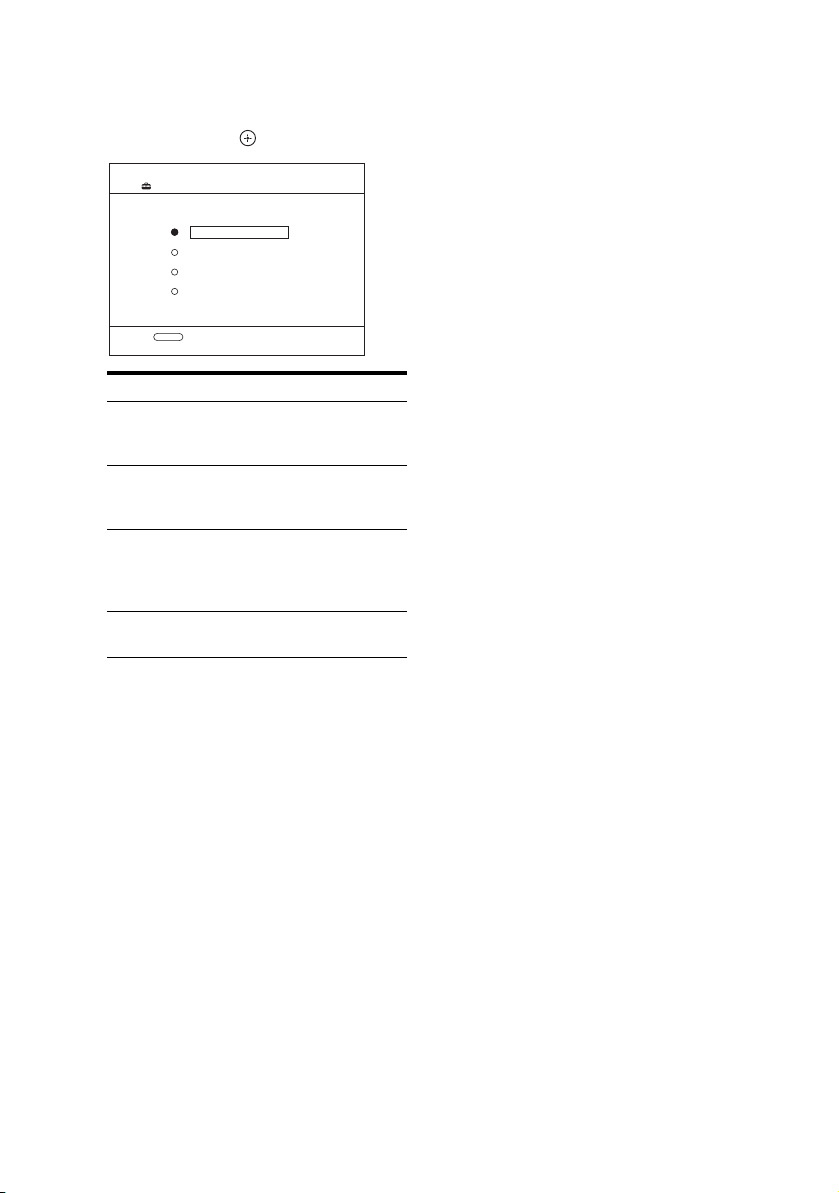
4 Select the Auto Calibration
Typ e.
Press V/v repeatedly to select “Auto Cal.
Type”, then press .
Auto Calibration
Auto Cal. Type
Full Flat
Engineer
Front Reference
Off
RETURN
Calibration type and explanation
Full Flat
Makes the measurement of frequency from
each speaker flat.
Engineer
Sets the frequency to one that matches that of
the Sony listening room standard.
Front Reference
Adjusts the characteristics of all the speakers
to match the characteristics of the front
speaker.
Off
Sets the Auto Calibration to off.
5 Disconnect the optimizer
microphone after you have
finished.
Note
If you have reposition your speaker, we recommend
that you perform Auto Calibration again to enjoy the
surround sound.
Tip
The size of a speaker (“Large”/“Small”) is
determined by the low frequency characteristics.
The measurement results may vary, depending on
the position of the optimizer microphone and
speakers, and the shape of the room. It is
recommended that you follow the measurement
results. However, you can change those settings in
the Speaker Settings menu. Save the measurement
results first, then try to change the settings if you
want.
GB
42
Page 43

Message list after Auto Calibration measurement
Display and explanation
Error Code 31
The SPEAKERS is set to off. Set it to others and perform the Auto Calibration again.
Error Code 32
None of the speakers were detected. Make sure that the optimizer microphone is connected properly and
perform the measurement again.
If the optimizer microphone is connected properly but the error code appears, the optimizer microphone cable
may be damaged or improperly connected.
Error Code 33
• None of the front speakers are connected or only one front speaker is connected.
• The optimizer microphone is not connected.
• Either the surround left or surround right speaker is not connected.
• Surround back speakers or front high speakers are connected even though surround speakers are not
connected. Connect the surround speaker(s) to the SPEAKERS SURROUND terminals.
• The surround back speaker is connected only to the SPEAKERS SURROUND BACK/FRONT HIGH/
BI-AMP/FRONT B R terminals. When you connect only one surround back speaker, connect it to the
SPEAKERS SURROUND BACK/FRONT HIGH/BI-AMP/FRONT B L terminals.
• Either the front left high or front right high speaker is not connected.
Warning 40
The measurement has completed. However, the noise level is high. You may be able to perform the
measurement properly if you try it again, even though the measurement cannot be performed in all
environments. Try to perform the measurement in a quiet environment.
Warning 41
The sound input from the optimizer microphone is outside the acceptable range. It is louder than the loudest
sound that can be measured. Try to perform the measurement when the environment is quiet enough to allow
proper measurement.
Warning 42
The volume of the receiver is out of the acceptable range. Try to perform the measurement when the
environment is quiet enough to allow proper measurement.
Warning 43
The distance and position of a subwoofer cannot be detected. This may be caused by noise. Try to perform the
measurement in a quiet environment.
NO WARNING
There is no warning information.
Preparing the Receiver
When “Error Code” appears
Check the error and perform Auto Calibration
again.
1 When you press , “RETRY?” appears.
2 Press B/b to select “YES”.
3 Press .
The measurement starts in five seconds.
When “Warning” appears
If a warning on the measurement result is
present, detailed information is displayed.
Press to return to step 1 of “3: Confirming/
saving the measurement results” (page 41).
Tip
Depending on the position of the subwoofer, the
measurement results for polarity may vary.
However, there will be no problems even if you
continue to use the receiver with that value.
43
GB
Page 44

Guide to on-screen display operation
You can display the menu of the receiver on
the TV screen and select the function you want
to use on the TV screen by pressing V/v/B/b
and on the remote.
To display the menu of the receiver on the TV
screen, make sure that the receiver is in “GUI
MODE” following the steps in “To turn “GUI
MODE” on and off” (page 44).
GUI MODE
V/v/B/b,
RETURN/
EXIT O
TOOL S/
OPTIONS
MENU
2 Press V/v repeatedly to select a
menu you want, then press .
The menu item list appears on the TV
screen.
Example: When you select “Settings”.
Auto Cal.
Speaker
Surround
EQ
Settings
Audio
3 Press V/v repeatedly to select
the menu item you want to
adjust, then press to enter
the menu item.
4 Repeat steps 2 and 3 to select
the parameter you want.
Using the menu
1 Press GUI MODE.
After “MENU ON” appears on the
display for a while, “GUI” appears and
the GUI menu appears on the TV screen.
Press MENU if the GUI menu does not
appear on the TV screen.
BD
Input
DVD
SAT/CATV
TV
VIDEO 1
44
Music
Video
GB
To return to the previous screen
Press RETURN/EXIT O.
To exit the menu
Press MENU.
To turn “GUI MODE” on and off
Press GUI MODE. “MENU ON” or “MENU
OFF” appears on the display, depending on the
mode selected.
Page 45

Overview of the main menus
Menu icon Description
Input Selects the input source
component connected to the
receiver (page 46).
Music Selects the music from the
audio component connected
to the DIGITAL MEDIA
PORT adapter (page 48).
Video Selects the images from the
video components connected
to the DIGITAL MEDIA
PORT adapter (page 48).
FM/AM/SR Selects the built-in FM/AM
radio or satellite tuner
connected (page 53, 57).
Settings You can adjust the settings of
the speakers, the surround
effect, equalizer, audio,
video and other inputs
connected to the HDMI jacks
(page 89).
2 Press V/v repeatedly to select a
menu you want, then press
or b to enter the menu.
The menu item list appears on the TV
screen.
Example: when you select “Input”.
BD
Input
DVD
SAT/CATV
TV
VIDEO 1
3 Press TOOLS/OPTIONS while
the menu item list is displayed.
The option menu appears.
Preparing the Receiver
Using the option menus
When you press TOOLS/OPTIONS, the
option menus for the selected main menu are
displayed. You can select a related function
without reselecting the menu.
1 Press GUI MODE.
After “MENU ON” appears on the
display for a while, “GUI” appears and
the GUI menu appears on the TV screen.
Press MENU if the GUI menu does not
appear on the TV screen.
BD
Input
Music
Video
DVD
SAT/CATV
TV
VIDEO 1
BD
Input
DVD
SAT/CATV
TV
VIDEO 1
Input Assign
Name lnput
4 Press V/v repeatedly to select
the option menu item you want,
then press or b.
5 Press V/v repeatedly to select
the parameter you want, then
press .
To exit the menu
Press MENU.
45
GB
Page 46
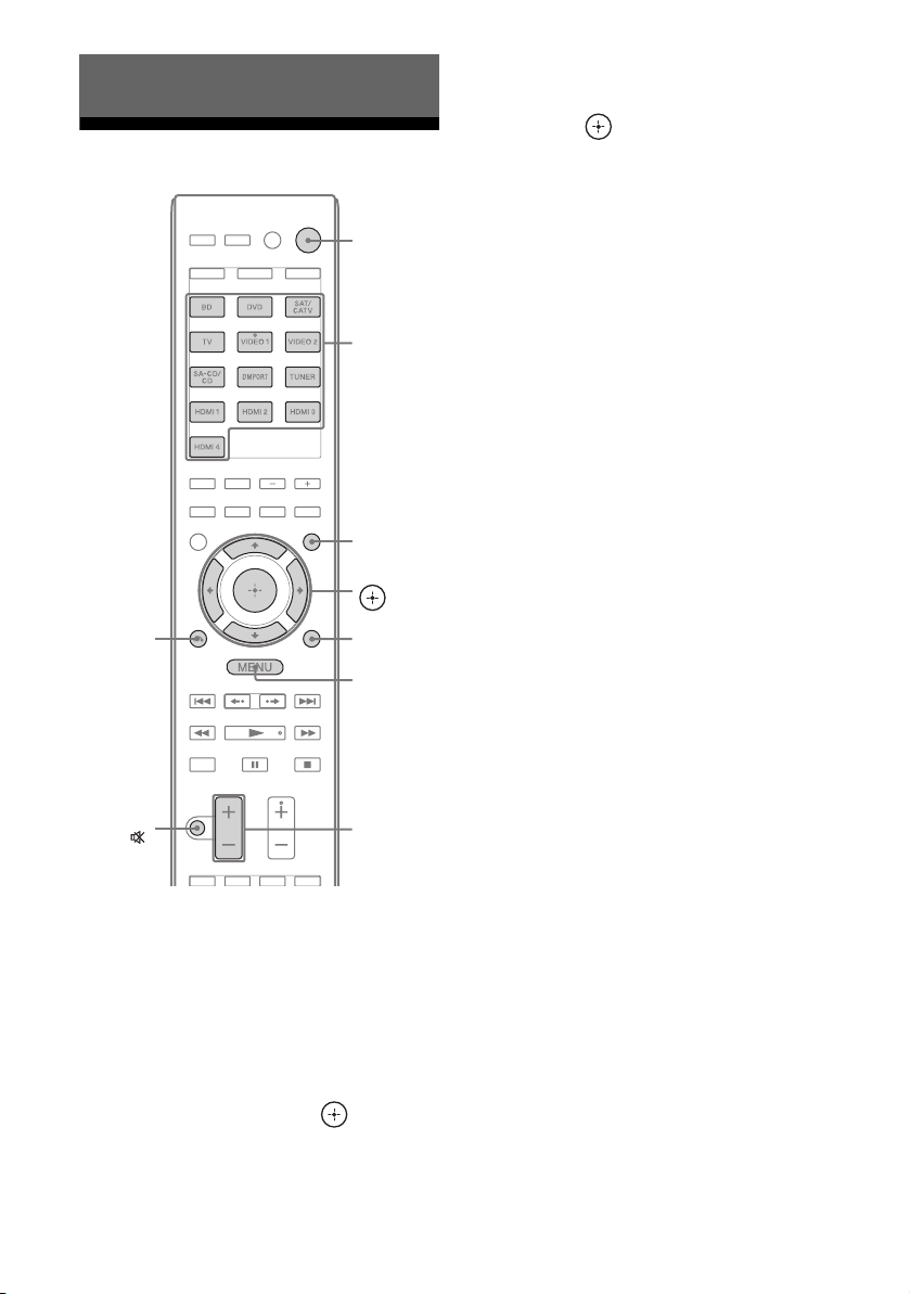
Basic Operations
Playback
3 Press V/v repeatedly to select
the component you want, then
press .
The selected input appears on the TV
screen.
RETURN/
EXIT O
MUTING/
Press GUI MODE.
1
After “MENU ON” appears on the
display for a while, “GUI” appears and
the GUI menu appears on the TV screen.
Press MENU if the GUI menu does not
appear on the TV screen.
?/1
Input
buttons
GUI MODE
V/v/B/b,
TOOLS/
OPTIONS
MENU
MASTER
VOL +/ –/
2 +/–
4 Turn on the component and
start playback.
5 Press MASTER VOL +/–
(RM-AAP051 only) or
(RM-AAP052 only) to adjust the
volume.
You can also use MASTER VOLUME on
the receiver.
2 +/–
6 Press SOUND FIELD +/– to
enjoy the surround sound.
You can also use 2CH/A.DIRECT,
A.F.D., MOVIE, MUSIC button on the
receiver.
For details, see page 65.
Tips
• You can press INPUT SELECTOR +/– on the
receiver repeatedly or press input buttons on the
remote to select the component you want.
• You can adjust the volume differently depending
on the speed with which you turn the MASTER
VOLUME on the receiver.
To turn the volume up or down quickly: turn the
knob quickly.
To make fine adjustment: turn the knob slowly.
• You can adjust the volume differently depending
on the length of time you press and hold the
MASTER VOL +/– (RM-AAP051 only) or
2 +/– (RM-AAP052 only) button on the remote.
To turn the volume up or down quickly: press and
hold the button.
To make a fine adjustment: press the button and
release it immediately.
2 Press V/v repeatedly to select
“Input”, then press or b.
The menu item list appears on the TV
screen.
GB
46
Page 47

To activate the muting function
Press MUTING (RM-AAP051 only) or
(RM-AAP052 only) on the remote.
You can also use MUTING on the receiver.
The muting function will be canceled when
you do the following.
• Press MUTING (RM-AAP051 only) or
(RM-AAP052 only) again.
• Increase the volume.
• Turn off the receiver.
• Perform Auto Calibration.
To cancel naming input
Press RETURN/EXIT O.
Viewing information on the
display
You can check the sound field, etc., by
changing the information on the display.
Basic Operations
To avoid damaging your
speakers
Before you turn off the receiver, be sure to turn
down the volume level.
Naming the input (Name Input)
You can enter a name of up to 8 characters for
inputs and display it.
This is convenient for labeling the jacks with
the names of the connected components.
1 Press V/v repeatedly on the
“Input” screen to select the
input you want.
2 Press TOOLS/OPTIONS.
The option menu appears.
3 Press V/v repeatedly to select
“Name Input”, then press .
BD
Input
DVD
SAT/CATV
TV
VIDEO 1
Input Assign
Name lnput
AMP
DISPLAY
Press AMP, then press DISPLAY
repeatedly.
You can also use DISPLAY on the receiver.
Each time you press DISPLAY, the display
will change as follows.
Input name you selected
name t Sound field currently applied t
Volume level t Stream information
a)
t Original input
FM and AM band
Program Service nameb) or preset station
a)
name
t Frequency t Program Type
b)
indication
Current Time indication (in 24-hour system
mode)
Volume level
t Radio Text indicationb) t
b)
t Sound field currently applied t
4 Press V/v/B/b to select a
character, then press .
The name you entered is registered.
continued
47
GB
Page 48

SIRIUS Satellite Radio (Models
of area code U2, CA2 only)
Channel name t Channel number t
Category name t Artist name/Feature t
Song/program title t Composer name t
Signal strength t Sound field type t
Volume level
a)
Index name appears only when you have assigned
one to the input or preset station (page 56). Index
name does not appear when only blank spaces
have been entered or it is the same as the input
name.
b)
During RDS reception only (Models of area code
CEK, ECE, AU1, TW2 only) (page 56).
Note
Character or marks may not be displayed for some
languages.
Tip
You cannot switch the display while “GUI” is shown
on the display. Press GUI MODE repeatedly to
select “MENU OFF”.
Enjoying sound/images from the components connected to the DIGITAL MEDIA PORT
The DIGITAL MEDIA PORT (DMPORT)
allows you to enjoy picture and sound from a
network system such as a portable audio/video
source or computer.
For details on connecting the DIGITAL
MEDIA PORT adapter, see “Connecting
audio components” (page 24).
You can use the following Sony DIGITAL
MEDIA PORT adapters:
• TDM-BT1/BT10 Bluetooth™ Wireless
Audio Adapter
• TDM-NW10 DIGITAL MEDIA PORT
Adapter
•TDM-NC1 Wireless Network Audio Client
• TDM-iP10/iP50 DIGITAL MEDIA PORT
Adapter
• TDM-MP10 DIGITAL MEDIA PORT
Adapter
48
The DIGITAL MEDIA PORT adapter is an
optional product.
Notes
• Do not connect an adapter other than the DIGITAL
MEDIA PORT adapter to the DMPORT jack.
• Before disconnecting the DIGITAL MEDIA
PORT adapter, be sure to turn off the receiver.
• Do not connect or disconnect the DIGITAL
MEDIA PORT adapter while the receiver is turned
on.
• Depending on the type of DIGITAL MEDIA
PORT adapter, video output may not be possible.
• The DIGITAL MEDIA PORT adapters are
available for purchase depending on the area.
GB
Page 49
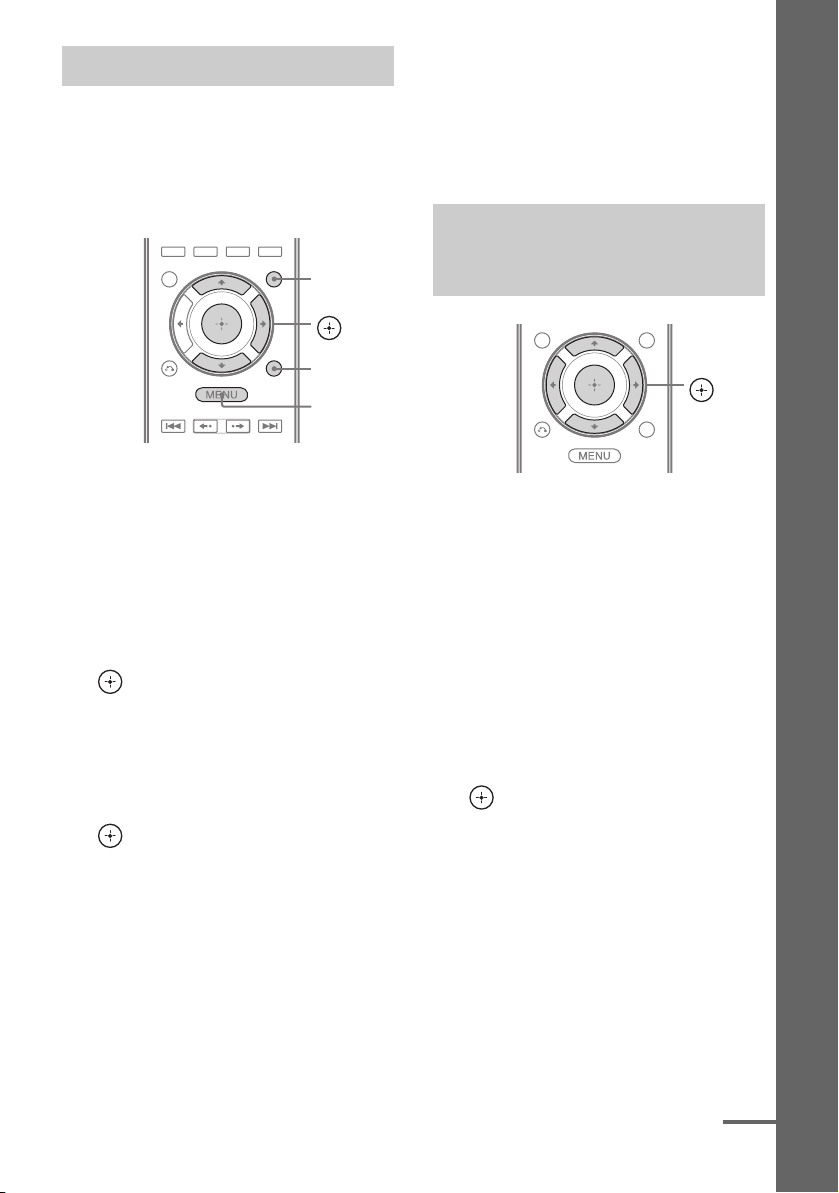
Selecting the operation screen
You can select an operation screen using the
GUI menu, depending on the DIGITAL
MEDIA PORT adapter you want to use. For
some adapter, such as TDM-BT1, the
operation screen is fixed and you cannot
change it on the GUI screen.
GUI MODE
V/v/b,
If the option menu does not appear on the
screen, refer to the operating instructions
of the connected component.
When an adapter other than iPod is
connected, a hierarchical menu does not
appear.
Operating the component
connected to the DIGITAL MEDIA
PORT adapter
Basic Operations
TOOLS/
OPTIONS
MENU
1 Press GUI MODE.
After “MENU ON” appears on the
display for a while, “GUI” appears and
the GUI menu appears on the TV screen.
Press MENU if the GUI menu does not
appear on the TV screen.
2 Press V/v repeatedly to select
“Music” or “Video”, then press
or b.
3 Press TOOLS/OPTIONS.
The option menu appears.
4 Press V/v repeatedly to select
the mode you want, then press
.
The details of each mode are as follows:
• System GUI
This mode is for the TDM-iP50 and
TDM-NC1. The list of tracks will be
displayed on the GUI screen of the
receiver. You can select a track you
want and play it back on each GUI
screen.
•iPod
This mode is for the TDM-iP50.
V/v/B/b,
To operate the TDM-iP50 or
TDM-NC1 using the GUI menu of
the receiver
1 Make sure that “System GUI” is
selected in step 4 in “Selecting
the operation screen”
(page 49).
2 Press V/v/B/b repeatedly to
select the content you want
from the contents list displayed
on the GUI screen, then press
to play it back.
The following content lists are just
examples. They may vary depending on
the components connected to the receiver.
continued
49
GB
Page 50

Contents list for audio
iPod Playlists > Playlist > Track
Artists > Artist > Album > Track
Albums > Album > Track
Songs > Track
Genres > Genre > Artist > Album > Track
Composers > Composer > Track
Audiobooks > Audiobook > Track
Network Client Music Surfin
Playlist
Web Radio
Music Library
a)
Displayed only when M-crew Server is connected.
b)
Displayed only when a DLNA server other than
M-crew Server is connected.
c)
Displayed as “Genre”, “Artist” or “Album”,
a)
> Albumc) > Track
a)
> Playlist > Track
a)
> Station > Program
b)
> Album > Track
depending on setting of “List Mode”.
Contents list for video
iPod Movies > Content
TV Shows > Episode > Content
Music Videos > Artist > Content
Video Playlists > Video Playlist > Content
Video Podcasts > Episode > Content
Playing the selected track
During playback of the selected track, the
displayed screen changes depending on the
DIGITAL MEDIA PORT adapter connected.
Example of a “System GUI” screen
Music Player
Title Sample
Artist Sampl...
Album Sample
RETURN OPTIONS
You can operate the components connected to
the DIGITAL MEDIA PORT adapter using
the following buttons on the remote of the
receiver.
b
B•/•
N
1/1
0:17
./>
m/M
x
X
3 Press MASTER VOL +/–
(RM-AAP051 only) or
(RM-AAP052 only) to adjust the
volume.
To operate the TDM-iP50 using
the iPod menu
Make sure that “iPod” is selected in step 4 in
“Selecting the operation screen” (page 49).
For details on operating the iPod, refer to the
operating instructions supplied with the iPod.
GB
50
2 +/–
To Do the following
Play Press N.
Pause Press X. To resume play,
press the button again.
Stop Press x.
Find the beginning of a
Press ..
track during playback, or
find the beginning of the
previous track
Find the beginning of the
Press >.
next track
Skip to the previous/next
Press B•/•b.
album
Go backward/forward Press m/M.*
* Fast-backward/forward while pressing and
holding the m/M button.
Page 51

Selecting the playback mode
1 Play back the track you want to
listen to following the steps in
“Operating the component
connected to the DIGITAL
MEDIA PORT adapter”
(page 49).
2 Press TOOLS/OPTIONS.
The option menu appears.
3 Press V/v repeatedly to select
“Repeat”, “Shuffle”, “List
Mode” or “Audiobook”, then
press or b.
4 Press V/v repeatedly to select
the mode you want to select
from the following, then press
.
x Repeat (TDM-iP50 only)
•OFF
•One
•All
x Shuffle (TDM-iP50 only)
•OFF
• Songs
• Albums
DIGITAL MEDIA PORT message
list
Message and explanation
No Adapter
The adapter is not connected.
No Device
There is no device connected to the adapter.
No Audio
No audio file was found.
Loading
The data is being read.
No Server*
There is no server connected.
No Track*
No track was found.
No Item
No item was found.
Connecting*
Connecting to the server.
Configuring*
The network is setting up.
Warning*
Check the display of the DIGITAL MEDIA PORT
adapter.
Searching*
Searching the server.
*TDM-NC1 only.
Basic Operations
x List Mode (TDM-NC1 only)
•All Tracks
•Disc List
• Artist List
•Genre List
x Audiobook (TDM-iP50 only)
•Low
• Normal
•High
51
GB
Page 52

Using the Sleep Timer
Recording using the
You can set the receiver to turn off
automatically at a specified time.
AMP
SLEEP
Press AMP, then press SLEEP
repeatedly while the power is on.
“SLEEP” lights up on the display.
Each time you press the button, the display
changes cyclically as follows:
0:30:00 t 1:00:00 t 1:30:00 t 2:00:00
t OFF
receiver
You can record from a video/audio component
using the receiver. Refer to the operating
instructions supplied with your recording
component.
Recording onto a CD-R
You can record onto a CD-R using the
receiver. Refer to the operating instructions
supplied with your CD recorder.
1 Press one of the input buttons
to select the playback
component.
You can also use INPUT SELECTOR +/–
on the receiver.
2 Prepare the playback
component for playing.
For example, tune to the radio station you
want to record (page 53).
3 Prepare the recording
component.
Insert a blank CD-R into the CD recorder
and adjust the recording level.
4 Start recording on the
recording component, then
start playback on the playback
component.
Note
Sound adjustments do not affect the signal output
from the SA-CD/CD/CD-R AUDIO OUT jacks.
Tip
To check the remaining time before the receiver
turns off, press SLEEP. The remaining time appears
on the display. If you press SLEEP again, the Sleep
Timer will be canceled.
GB
52
Page 53
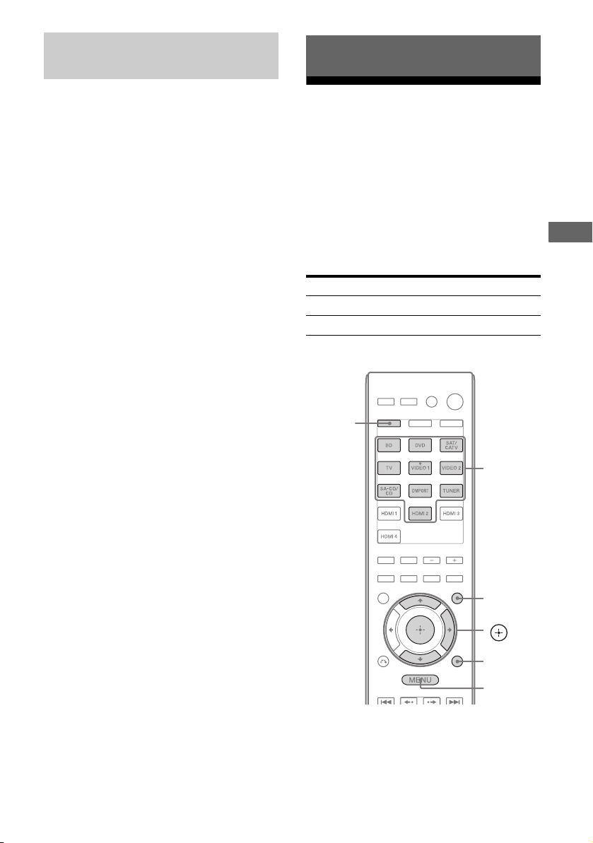
Recording onto a recording
media
Tuner Operations
1 Press the input button of the
playback component.
You can also use INPUT SELECTOR
+/– on the receiver.
2 Prepare the playback
component for playing.
For example, insert the video tape you
want to copy into the VCR.
3 Prepare the recording
component.
Insert a blank video tape, etc. into the
recording component (connected to
VIDEO 1 OUT jacks) for recording.
4 Start recording on the
recording component, then
start playback on the playback
component.
Notes
• Some sources contain copy guards to prevent
recording. In this case, you may not be able to
record from the source.
• Only analog input signals are output from the
analog output jack (for recording).
• HDMI sound cannot be recorded.
Listening to FM/AM radio
You can listen to FM and AM broadcasts
through the built-in tuner. Before operation,
make sure you have connected the FM and
AM antennas (aerials) to the receiver (page
35).
Tip
The tuning scale for direct tuning differs depending
on the area code as shown in the following table. For
details on area codes, see page 4.
Area code FM AM
U2, CA2 100 kHz 10 kHz*
CEK, ECE, AU1, TW2 50 kHz 9 kHz
* The AM tuning scale can be changed (page 55).
SHIFT
Numeric
buttons
Tuner Operations
GUI MODE
V/v/b,
TOOLS/
OPTIONS
MENU
53
GB
Page 54

Tuning into a station
automatically (Auto Tuning)
Tuning into a station directly
(Direct Tuning)
1 Press GUI MODE.
After “MENU ON” appears on the
display for a while, “GUI” appears and
the GUI menu appears on the TV screen.
Press MENU if the GUI menu does not
appear on the TV screen.
2 Press V/v repeatedly to select
“FM” or “AM”, then press or
b.
The FM or AM menu list appears on the
TV screen.
3 Press V/v repeatedly to select
“Auto Tuning”, then press
or b.
4 Press V/v.
Press V to scan from low to high, press v
to scan from high to low.
The receiver stops scanning whenever a
station is received.
In case of poor FM stereo
reception
1 Tune in the station you want to listen to
using Auto Tuning, Direct Tuning
(page 54), or select the preset station you
want (page 55).
2 Press TOOLS/OPTIONS.
3 Press V/v repeatedly to select “FM Mode”,
then press or b.
4 Press V/v repeatedly to select “MONO”,
then press .
You can enter the frequency of a station
directly by using the numeric buttons.
1 Press GUI MODE.
After “MENU ON” appears on the
display for a while, “GUI” appears and
the GUI menu appears on the TV screen.
Press MENU if the GUI menu does not
appear on the TV screen.
2 Press V/v repeatedly to select
“FM” or “AM”, then press or
b.
The FM or AM menu list appears on the
TV screen.
3 Press V/v repeatedly to select
“Direct Tuning”, then press
or b.
4 Press SHIFT, then press
numeric buttons to enter the
frequency.
Example 1: FM 102.50 MHz
Select 1 b 0 b 2 b 5 (b 0*)
Example 2: AM 1,350 kHz
Select 1 b 3 b 5 b 0
* Press 0 for models of area code CEK,
ECE, AU1, TW2 only.
Tip
If you have tuned in an AM station, adjust
the direction of the AM loop antenna
(aerial) for optimum reception.
5 Press .
54
If you cannot tune in a station
“– – – .– – MHz” appears and then the screen
returns to the current frequency.
Make sure you have entered the right
frequency. If not, repeat step 4. If you still
cannot tune in a station, the frequency is not
used in your area.
GB
Page 55

Changing the AM tuning scale
(Models of area code U2, CA2 only)
You can change the AM tuning scale to either
9 kHz or 10 kHz on the receiver.
?/1
Presetting FM/AM radio stations (Preset Tuning)
You can preset up to 30 FM and 30 AM
stations. Then you can easily tune in the
stations you often listen to.
GUI MODE
V/v/b,
DISPLAY
1 Press ?/1 to turn off the
receiver.
2 While holding down DISPLAY,
press ?/1 on the receiver.
3 Change the current AM tuning
scale to 9 kHz (or 10 kHz).
To reset the scale to 10 kHz (or 9 kHz),
repeat the procedure above.
Note
All preset stations will be erased when you change
the tuning scale.
TOOLS/
OPTIONS
MENU
1 Press GUI MODE.
After “MENU ON” appears on the
display for a while, “GUI” appears and
the GUI menu appears on the TV screen.
Press MENU if the GUI menu does not
appear on the TV screen.
2 Press V/v repeatedly to select
“FM” or “AM”, then press or
b.
The FM or AM menu list appears on the
TV screen.
3 Tune in the station that you
want to preset using Auto
Tuning (page 54) or Direct
Tuning (page 54).
In case of poor FM stereo reception,
switch the FM reception mode (page 54).
4 Press TOOLS/OPTIONS.
The option menu appears.
Tuner Operations
5 Press V/v repeatedly to select
“Memory”, then press or b.
continued
55
GB
Page 56

6 Press V/v repeatedly to select a
preset number, then press .
The station is stored as the selected preset
number.
7 Repeat steps 3 to 6 to preset
another station.
You can store station as follows:
• AM band: AM 1 to AM 30
• FM band: FM 1 to FM 30
Tuning to preset stations
1 Repeat steps 1 and 2 of
“Presetting FM/AM radio
stations (Preset Tuning)”.
2 Press V/v repeatedly to select
the preset station you want.
Preset numbers from 1 to 30 are available.
Naming preset stations (Name
Input)
1 On “FM” or “AM” screen, press
V/v repeatedly to select the
preset number on which you
have stored the station and
which you want to name.
2 Press TOOLS/OPTIONS.
The option menu appears.
3 Press V/v repeatedly to select
“Name Input”, then press or
b.
Using the Radio Data System (RDS)
(Models of area code CEK, ECE,
AU1, TW2 only)
This receiver allows you to use Radio Data
System (RDS), which enables radio stations to
send additional information along with the
regular program signal. This receiver offers
convenient RDS features, such as Program
Service name display.
Notes
• RDS is operable only for FM stations.
• Not all FM stations provide RDS service, nor do
they provide the same type of services. If you are
not familiar with the RDS services in your area,
check with your local radio stations for details.
Receiving RDS broadcasts
Simply select a station on the FM
band using Direct Tuning (page 54),
Auto Tuning (page 54), or Preset
Tuning (page 55).
When you tune in a station that provides RDS
services, “RDS” lights up and the program
service name appears on the display.
Note
RDS may not work properly if the station you tuned
to is not transmitting the RDS signal properly or if
the signal strength is weak.
Tip
When a Program Service name is displayed, you can
check the frequency by pressing DISPLAY
repeatedly (page 47).
4 Press V/v/B/b to select a
character, then press .
The name you entered is registered.
GB
56
Page 57

Listening to Satellite Radio
(Models of area code U2, CA2 only)
To listen to Satellite Radio, you’ll need to
connect a SIRIUS Satellite Radio tuner (sold
separately) to your Sirius-Ready receiver.
SIRIUS Satellite Radio is available to
residents of the US (except Alaska and
Hawaii) and Canada.
Satellite Radio delivers a variety of
commercial-free music from categories
ranging from Pop, Rock, Country, R&B,
Dance, Jazz, Classical and many more plus
coverage of all the top professional and
college sports including play by play games
from select leagues and teams. Additional
programming includes expert sports talk,
uncensored entertainment, comedy, family
programming, local traffic and weather and
news from your most trusted sources.
Once you’ve purchased a SIRIUS tuner you’ll
need to activate it and subscribe to begin
enjoying the service. Easy to follow
installation and setup instructions are provided
with the SIRIUS tuner. There are a variety of
programming packages available, including
the option of adding “The Best of XM”
programming to the SIRIUS service. The
“Best of XM” service is not available to
SIRIUS Canada subscribers at this time.
Please check with SIRIUS Canada for any
updates using the numbers and web address
below.
SIRIUS and all related marks and logos are
trademarks of Sirius XM Radio Inc. and its
subsidiaries. All other marks and logos are the
property of their respective owners. All rights
reserved. SIRIUS subscription sold separately.
Taxes and a one-time activation fee may apply.
SIRIUS tuner required (sold separately) to receive
the SIRIUS service. All programming and fees
subject to change. It is prohibited to copy,
decompile, disassemble, reverse engineer, hack,
manipulate or otherwise make available any
technology or software incorporated in receivers
compatible with the SIRIUS Satellite Radio System.
Service not available in Alaska or Hawaii.
Tuner Operations
Family friendly packages are also available to
restrict channels featuring content that may be
inappropriate for children.
To subscribe to SIRIUS, U.S. and Canadian
customers can call 1-888-539-SIRI (1-888539-7474) or visit sirius.com (US) or
siriuscanada.ca (Canada).
57
GB
Page 58

Connecting the SIRIUS
Preparing to listen to the
Satellite Radio
Connect the SiriusConnect Home tuner. When
you use the SiriusConnect Home tuner with
this receiver, be sure to connect the AC power
adaptor supplied with the tuner to a wall outlet.
SIRIUS jack
Note
Keep the SiriusConnect Home tuner, antenna, and
AC power adaptor away from the speaker cords and
the power cord to avoid picking up noise.
SIRIUS Satellite Radio
GUI MODE
V/v/b,
TOOL S/
OPTIONS
MENU
Checking the SIRIUS Radio ID
Press GUI MODE.
1
After “MENU ON” appears on the
display for a while, “GUI” appears and
the GUI menu appears on the TV screen.
Press MENU if the GUI menu does not
appear on the TV screen.
2 Press V/v repeatedly to select
“SR”, then press or b.
3 Press TOOLS/OPTIONS, then
press V/v repeatedly to select
“Sirius ID”, then press or b.
58
4 Check the SIRIUS ID on the TV
screen and write it in the space
provided here.
ID:_________________________________
You can also check the SIRIUS ID using
the display on the receiver.
GB
Page 59

Checking receiving conditions
(Antenna Aiming)
1 Press GUI MODE.
After “MENU ON” appears on the
display for a while, “GUI” appears and
the GUI menu appears on the TV screen.
Press MENU if the GUI menu does not
appear on the TV screen.
2 Press V/v repeatedly to select
“SR”, then press or b.
Selecting a channel of the SIRIUS Satellite Radio
SHIFT
Numeric
buttons
3 Press TOOLS/OPTIONS, then
press V/v repeatedly to select
“Antenna”, then press or b.
4 While checking the quality of
the reception, adjust the
direction of the antenna to
obtain the best reception.
To exit the menu
Press MENU.
Tuner Operations
GUI MODE
V/v/b,
TOOLS/
OPTIONS
MENU
Selecting a channel by category
(Category Mode)
You can select a channel from one category or
all the categories.
1 Press GUI MODE.
After “MENU ON” appears on the
display for a while, “GUI” appears and
the GUI menu appears on the TV screen.
Press MENU if the GUI menu does not
appear on the TV screen.
2 Press V/v repeatedly to select
“SR”, then press or b.
continued
59
GB
Page 60

3 Press V/v repeatedly to select
the category, then press or
b.
• All: You can select a channel from all
the categories.
• (category name): You can select a
channel from one category.
Note
When the “Preset Mode” screen is displayed,
press TOOLS/OPTIONS, then press V/v
repeatedly to select “Category Mode”.
4 Press V/v repeatedly to select
the channel, then press .
The selected channel is being received.
The channel information is displayed on
the TV screen.
Note
When you select a channel in the “Category Mode”,
the channel you selected may not be the one in the
category you want. This is because one channel may
belong to more than one category.
Selecting a channel by inputting
the channel number directly
(Direct Tuning)
1 Press GUI MODE.
After “MENU ON” appears on the
display for a while, “GUI” appears and
the GUI menu appears on the TV screen.
Press MENU if the GUI menu does not
appear on the TV screen.
2 Press V/v repeatedly to select
“SR”, then press or b.
3 Press TOOLS/OPTIONS.
The option menu appears.
4 Press V/v repeatedly to select
“Direct Tuning”, then press
or b.
5 Press SHIFT, then press the
numeric buttons to enter the
channel number.
6 Press .
The selected channel is tuned in.
60
GB
Page 61

Presetting SIRIUS Satellite Radio channels
You can select the channels you want directly
by presetting them using the preset numbers.
You can preset up to 30 SIRIUS Satellite
Radio channels.
6 Press V/v repeatedly to select
the preset channel you want,
then press .
Preset channels from 1 to 30 are available,
and a default channel is preset for all the
preset channels when you purchase the
receiver.
The selected channel is registered as the
preset channel you selected in step 3.
GUI MODE
V/v/b,
TOOL S/
OPTIONS
MENU
Presetting channels using the
preset numbers
1 Press GUI MODE.
After “MENU ON” appears on the
display for a while, “GUI” appears and
the GUI menu appears on the TV screen.
Press MENU if the GUI menu does not
appear on the TV screen.
2 Press V/v repeatedly to select
“SR”, then press or b.
3 Select a channel you want to
preset using Category Tuning
(page 59) or Direct Tuning
(page 60).
7 Repeat steps 3 to 6 to preset
another channel.
Tuner Operations
Selecting the channel by using
the preset numbers
1 Repeat steps 1 and 2 of
“Presetting channels using the
preset numbers” (page 61).
2 Press V/v repeatedly to select
the preset number from the
preset list, then press .
You can select stored preset channels
from 1 to 30.
Notes
• The channel information you have preset may be
changed if SIRIUS Satellite Radio Inc. change
their channel programming.
• When the “Category Mode” screen is displayed,
press TOOLS/OPTIONS, then press V/v
repeatedly to select “Preset Mode”.
4 Press TOOLS/OPTIONS.
The option menu appears.
5 Press V/v repeatedly to select
“Memory”, then press or b.
61
GB
Page 62

Restricting access to
specific channels
4 Press V/v repeatedly to select
“ON”, then press .
“Enter your 4-digit lock code.” appears.
(Parental Lock)
You can restrict access to certain channels
using your own lock code. The lock code is set
to “0000” as the default.
Change the lock code before you use this
function for the first time. See “To change the
lock code (Lock Code)” (page 62).
SHIFT
Numeric
buttons
V/v/b,
RETURN/
EXIT O
TOOLS/
OPTIONS
1 Select a channel you want to
lock using Category Mode
(page 59) or Direct Tuning
(page 60).
2 Press TOOLS/OPTIONS.
The option menu appears.
5 Press SHIFT, then press the
numeric buttons to enter your
4-digit lock code.
“The channel has been locked.” appears
and the Parental Lock is set.
To delete the numbers you have entered,
go back to step 2 by pressing RETURN/
EXIT O, and then repeat the procedure
above from step 2.
To change the lock code (Lock
Code)
1
Select a channel you want to change
the lock code using Category Mode
(page 59) or Direct Tuning (page 60).
2 Press TOOLS/OPTIONS.
The option menu appears.
3 Press V/v repeatedly to select “Lock
Code”, then press .
“Enter your 4-digit lock code.” appears.
4 Press SHIFT, then press the numeric
buttons to enter your 4-digit lock code.
“Enter a new lock code.” appears.
5 Enter a new 4-digit lock code using the
numeric buttons.
“To confirm, enter your new lock code
again.” appears.
6 Reenter the new lock code with the
numeric buttons.
“The lock code has been changed.”
appears.
3 Press V/v repeatedly to select
“Parental Lock”, then press
or b.
GB
62
Page 63

To listen to the locked channels
1
Select a locked channel you want to
listen to using Direct Tuning (page 60).
“Enter your 4-digit lock code.” appears.
2 Press SHIFT, then press the numeric
buttons to enter your 4-digit lock code.
The channel is tuned in.
To cancel the Parental Lock
1
Select a channel you want to unlock
using Direct Tuning (page 60).
2 Press TOOLS/OPTIONS.
The option menu appears.
3 Press V/v repeatedly to select
“Parental Lock”, then press or b.
4 Press V/v repeatedly to select “OFF”,
then press .
“Enter your 4-digit lock code.” appears.
5 Press SHIFT, then press the numeric
buttons to enter your 4-digit lock code.
“The channel has been unlocked.” appears
and the channel is unlocked.
Notes
• When you select a channel using Category Mode,
locked channels are skipped.
• When the receiver is reset to the initial settings, the
lock code returns to the default (0000), but the
Parental Lock settings are not removed.
• You cannot preset locked channels. If you set the
Parental Lock for a preset channel, the preset
information for that channel returns to the default.
• You cannot set the Parental Lock for channel 0 and
channel 184.
• You can set only one lock code on the receiver.
You cannot set individual lock codes for each
channel.
Tuner Operations
continued
63
GB
Page 64

SIRIUS Satellite Radio message list
Message
appears on
TV screen
[Display]
Antenna
[ANTENNA]
Acquiring
[ACQUIRING]
UNSUB CH
[CALL 888,
539-SIRI]*
SR Tuner
[SR TUNER]
Invalid
[INVALID]
Locked CH
[LOCKED CH]
SUB UPDT
[SUB UPDT]
Updating
[UPDATING]
FW UPDT
[FW UPDT]
– – – – There is no text information in the
* “CALL 888” and “539-SIRI” appears on the display alternately.
Explanation Remedies
The antenna is not connected
properly.
The receiving condition is not
good.
You have not subscribed for the
selected channel.
The SiriusConnect Home tuner is
not connected properly.
You have entered an invalid
channel number.
The selected channel is locked. —
The subscription information has
been updated.
Channel information is being
updated.
The SiriusConnect Home tuner
firmware is being updated.
channel.
Check the connection between the SiriusConnect
Home tuner and the antenna.
Try moving the antenna to another location.
For details about the antenna location, refer to the
operating instructions supplied with the SiriusConnect
Home tuner.
—
Check all the connections, and then turn the system on
ag ain. Also ma ke sure if the AC adaptor supplied with
the SiriusConnect Home tuner is connected to a wall
socket.
The channel to be tuned-in is void due to the change
by the broadcast service, or the receiving condition is
not good.
—
—
—
This is not an error. The text information may not be
displayed depending on the system condition, for
example, right after the system has received a channel.
64
GB
Page 65

Enjoying Surround Sound
Note
You cannot select “Analog Direct” when you select
DVD, DMPORT and HDMI 1-4 as input.
Selecting the sound field
This receiver can create multi channel
surround sound. You can select one of the
optimized sound fields from the receiver’s
preprogrammed sound fields.
.
SOUND
FIELD +/–
Press SOUND FIELD +/– repeatedly
to select the sound field you want.
You can also use 2CH/A.DIRECT, A.F.D.,
MOVIE or MUSIC on the receiver.
2 channel sound mode
You can switch the output sound to 2 channel
sound regardless of the recording formats of
the software you are using, the playback
component connected, or the sound field
settings of the receiver.
Auto Format Direct (A.F.D.)
mode
The Auto Format Direct (A.F.D.) mode allows
you to listen to high fidelity sound and select
the decoding mode for listening to a 2 channel
stereo sound as multi channel sound.
x A.F.D. AUTO (A.F.D. Auto)
Presets the sound as it was recorded/encoded
without adding any surround effects.
x MULTI ST. (Multi Stereo)
Outputs 2 channel left/right signals from all
speakers. However, sound may not be output
from certain speakers depending on the
speaker settings.
Movie mode
You can take advantage of surround sound
simply by selecting one of the receiver’s preprogrammed sound fields. They bring the
exciting and powerful sound of movie theaters
into your home.
Enjoying Surround Sound
x 2CH ST. (2ch Stereo)
The receiver outputs the sound from the front
left/right speakers only. There is no sound
from the subwoofer.
Standard 2 channel stereo sources completely
bypass the sound field processing and multi
channel surround formats are downmixed to 2
channel.
x A. DIRECT (Analog Direct)
You can switch the audio of the selected input
to 2 channel analog input. This function
enables you to enjoy high quality analog
sources without any adjustment.
When using this function, only the volume and
front speaker level can be adjusted.
x C.ST.EX A (Cinema St EX A
DCS )
Reproduces the sound characteristics of the
Sony Pictures Entertainment “Cary Grant
Theater” cinema production studio. This is a
standard mode, great for watching almost any
type of movie.
x C.ST.EX B (Cinema St EX B
DCS )
Reproduces the sound characteristics of the
Sony Pictures Entertainment “Kim Novak
Theater” cinema production studio. This mode
is ideal for watching science-fiction or action
movies with lots of sound effects.
continued
65
GB
Page 66

x C.ST.EX C (Cinema St EX C
DCS )
Reproduces the sound characteristics of the
Sony Pictures Entertainment scoring stage.
This mode is ideal for watching musicals or
films where orchestra music is featured in the
soundtrack.
x V.MULTI DIM. (V.M. Dimension
DCS )
Creates many virtual speakers from a single
pair of actual surround speakers.
x PLII MV (PLII Movie)
Performs Dolby Pro Logic II Movie mode
decoding. This setting is ideal for movies
encoded in Dolby Surround. In addition, this
mode can reproduce sound in 5.1 channel for
watching videos of overdubbed or old movies.
x PLIIx MV (PLIIx Movie)
Performs Dolby Pro Logic IIx Movie mode
decoding. This setting expands Dolby Pro
Logic II Movie or Dolby Digital 5.1 to discrete
7.1 movie channels.
x PLIIz (PLIIz Height)
Performs Dolby Pro Logic IIz mode decoding.
This setting increases flexibility to expand a
5.1 to a 7.1 channel system. Its vertical
component gives a dimension of presence and
depth.
x NEO6 CIN (Neo:6 Cinema)
Performs DTS Neo:6 Cinema mode decoding.
A source recorded in 2 channel format is
decoded into 7 channels.
x HALL (Hall)
Reproduces the acoustics of a classical concert
hall.
x JAZZ (Jazz Club)
Reproduces the acoustics of a jazz club.
x CONCERT (Live Concert)
Reproduces the acoustics of a 300-seat live
house.
x STADIUM (Stadium)
Reproduces the feeling of a large open-air
stadium.
x SPORTS (Sports)
Reproduces the feeling of sports broadcasting.
x PORTABLE (Portable Audio)
Reproduces a clear enhanced sound image
from your portable audio device. This mode is
ideal for MP3 and other compressed music.
x PLII MS (PLII Music)
Perform Dolby Pro Logic II Music mode
decoding. This setting is ideal for normal
stereo sources such as CDs.
x PLIIx MS (PLIIx Music)
Performs Dolby Pro Logic IIx Music mode
decoding. This setting is ideal for normal
stereo sources such as CDs.
x PLIIz (PLIIz Height)
Performs Dolby Pro Logic IIz mode decoding.
This setting increases flexibility to expand a
5.1 to a 7.1 channel system. Its vertical
component gives a dimension of presence and
depth.
Music mode
You can take advantage of surround sound
simply by selecting one of the receiver’s
preprogrammed sound fields. They bring the
exciting and powerful sound of concert halls
into your home.
GB
66
x NEO6 MUS (Neo:6 Music)
Performs DTS Neo:6 Music mode decoding.
A source recorded in 2 channel format is
decoded into 7 channels. This setting is ideal
for normal stereo sources such as CDs.
Page 67

When headphones are
connected
You can only select this sound field if the
headphones are connected to the receiver.
x HP 2CH (HP (2 ch))
This mode is selected automatically if you use
headphones (except Analog Direct). Standard
2 channel stereo sources completely bypass
the sound field processing and multi channel
surround formats are downmixed to 2
channels except LFE signals.
Note
When headphones are connected to the S-AIR
surround amplifier, the sound field is automatically
set to “HP (2 ch)”.
x HP DIRECT (HP (Direct))
This mode is selected automatically if you use
headphones when “Analog Direct” is selected.
Outputs the analog signals without processing
by the equalizer, sound field, etc.
If you connect a subwoofer
This receiver will generate a low frequency
signal for output to the subwoofer when there
is no LFE signal, which is a low-pass sound
effect output from a subwoofer to a 2 channel
signal. However, the low frequency signal is
not generated for “Neo:6 Cinema” or “Neo:6
Music” when all speakers are set to “Large”.
In order to take full advantage of the Dolby
Digital bass redirection circuitry, we
recommend setting the subwoofer’s cut off
frequency as high as possible.
Notes on sound fields
• Depending on the speaker pattern settings, some
sound fields may not be available.
• You cannot select PLIIx and PLIIz at the same
time.
– PLIIx is available only when the speaker pattern
is set to a setting with surround back speaker(s).
– PLIIz is available only when the speaker pattern
is set to a setting with front high speakers.
• The sound fields for music and movies do not work
in the following cases.
– Signals with a sampling frequency of more than
48 kHz are being received.
– Signals with more than 5.1 channel are being
received (except PLIIz).
• When one of the sound fields for music is selected,
no sound is output from the subwoofer if all the
speakers are set to “Large” on the Speaker Settings
menu. However, the sound will be output from the
subwoofer if
– the digital input signal contains LFE signals.
– the front or surround speakers are set to “Small”.
– the sound field for movie is selected.
– “Portable Audio” is selected.
• The effects provided by the virtual speakers may
cause increased noise in the playback signal.
• When listening with sound fields that employ the
virtual speakers, you will not be able to hear any
sound coming directly from the surround speakers.
Tips
• You can identify the encoding format of DVD
software, etc., by looking at the logo on the
package.
• Dolby Pro Logic IIx and Dolby Pro Logic IIz
decoding are effective when multi channel signals
are input.
• Sound fields with DCS marks use DCS
technology. For details on Digital Cinema Sound
(DCS), see “Glossary” (page 117).
To turn off the surround effect
for movie/music
Press SOUND FIELD +/– repeatedly to select
“2CH ST.” or “A.F.D. AUTO”.
You can also press 2CH/A.DIRECT
repeatedly on the receiver to select “2CH ST.”
or press A.F.D. repeatedly on the receiver to
select “A.F.D. AUTO”.
Enjoying Surround Sound
67
GB
Page 68

When connecting Blu-ray disc players and other next generation HD
players
Digital audio formats that this receiver can decode depend on digital audio input jacks for the
components connected. This receiver supports the following audio formats.
Audio format
Maximum number
of channels
Dolby Digital 5.1 aa
Dolby Digital EX 6.1 aa
Dolby Digital Plus
Dolby TrueHD
a)
a)
7.1 × a
7.1 × a
DTS 5.1 aa
DTS-ES 6.1 aa
DTS 96/24 5.1 aa
DTS-HD
High Resolution Audio
DTS-HD
Master Audio
a)b)
Multi channel Linear PCM
a)
Audio signals are output in another format if the playback component does not correspond to the format. For
details, refer to the operating instructions of the playback component.
b)
Signals with a sampling frequency of more than 96 kHz are played back at 96 kHz or 88.2 kHz.
a)
a)
7.1
7.1
7.1 × a
Connection of the playback component and
the receiver
COAXIAL/OPTICAL HDMI
× a
× a
68
GB
Page 69

Enjoying the surround
effect at low volume
levels
(NIGHT MODE)
This function allows you to retain a theater like
environment at low volume levels. This
function can be used with other sound fields.
When watching a movie late at night, you will
be able to hear the dialog clearly even at a low
volume level.
NIGHT
MODE
Press NIGHT MODE to select
“NIGHT ON”.
The NIGHT MODE function is activated. The
NIGHT MODE is set to on and off as you
press NIGHT MODE.
Note
This function does not work in the following cases.
– Sound Field is set to “Analog Direct”.
– Signals with a sampling frequency of more than
48 kHz are being received.
Tip
While this function is on, the Bass, Treble, and
Effect Levels increase, and “D.Range Comp” is
automatically set to “MAX”.
Resetting sound fields to the initial settings
Be sure to use the buttons on the receiver for
this operation.
?/1
MUSIC
1 Press ?/1 to turn off the
receiver.
2 While holding down MUSIC,
press ?/1.
“S.F. CLEAR” appears on the display and
all sound fields are reset to their initial
setting.
Enjoying Surround Sound
69
GB
Page 70

“BRAVIA” Sync Features
What is “BRAVIA” Sync?
“BRAVIA” Sync is compatible with Sony TV,
Blu-ray disc/DVD player, AV amplifier, etc.,
that is equipped with the Control for HDMI
function.
By connecting Sony components that are
compatible with the “BRAVIA” Sync with an
HDMI cable (not supplied), operation is
simplified as follows:
• One-Touch Play (page 72)
• System Audio Control (page 72)
• System Power Off (page 73)
• Theater/Theatre Mode Sync (page 73)
• Audio Return Channel (page 74)
Control for HDMI is a mutual control function
standard used by HDMI CEC (Consumer
Electronics Control) for HDMI (HighDefinition Multimedia Interface).
We recommend that you connect the receiver
to products featuring “BRAVIA” Sync.
Note
Depending on the connected component, the
Control for HDMI function may not work. Refer to
the operating instructions of the component.
Preparing for the “BRAVIA” Sync
The receiver is compatible with the “Control
for HDMI-Easy Setting” function.
• If your TV is compatible with the “Control
for HDMI-Easy Setting” function, you can
set the Control for HDMI function of the
receiver and playback components
automatically by setting the TV (page 70).
• If your TV is not compatible with the
“Control for HDMI-Easy Setting” function,
set the Control for HDMI function of the
receiver, playback components and TV
individually (page 71).
If your TV is compatible with the
“Control for HDMI-Easy Setting”
function
The Control for HDMI function of the receiver
can be turned on simultaneously by turning on
the Control for HDMI function of the TV.
1 Connect the receiver, TV and playback
components via HDMI connection
(page 27).
(The respective components must be
compatible with the Control for HDMI
function).
2 Turn on the receiver, TV and playback
components.
70
3 Turn the Control for HDMI function of
the TV on.
The Control for HDMI function of the
receiver and all the connected components
are turned on simultaneously. When the
setup is completed, “COMPLETE” will
appear.
For details on setup of the TV, refer to the
operating instructions of your TV.
GB
Page 71

If your TV is not compatible with
the “Control for HDMI-Easy
Setting” function
GUI MODE
V/v/b,
MENU
Perform the steps given in “If your TV is
1
compatible with the “Control for HDMIEasy Setting” function” (page 70).
2 Press GUI MODE.
After “MENU ON” appears on the display
for a while, “GUI” appears and the GUI
menu appears on the TV screen.
Press MENU if the GUI menu does not
appear on the TV screen.
3 Press V/v repeatedly to select
“Settings”, then press or b.
The Settings menu list appears on the TV
screen.
4 Press V/v repeatedly to select “HDMI”,
then press or b.
5 Press V/v repeatedly to select “Ctrl for
HDMI”, then press or b.
6 Press V/v repeatedly to select “ON”,
then press .
The Control for HDMI function is set to on.
7 Set the Control for HDMI function of the
connected component to on.
If the Control for HDMI function for the
connected component is already set to on,
you do not need to change the setting.
For details on setting the TV and connected
components, refer to the operating
instructions of the respective components.
Notes
• Before you do the “Control for HDMI-Easy
Setting” from the TV, be sure to turn on the TV,
connected components and receiver.
• If the playback components cannot function after
you have made the settings for “Control for HDMIEasy Setting”, check the Control for HDMI setting
on your TV.
• If the connected components do not support
“Control for HDMI-Easy Setting”, you need to set
the Control for HDMI function for the connected
components to on before you perform the “Control
for HDMI-Easy Setting” from the TV.
“BRAVIA” Sync Features
71
GB
Page 72

Playing back components
Enjoying the TV sound
with one-touch operation
(One-Touch Play)
By a simple operation (one-touch),
components connected to the receiver with
HDMI connections start automatically. You
can enjoy the sound/image using connected
components.
When you set “Pass Through” to “AUTO” or
“ON”, sound and image can be output only
from the TV while the receiver remains in
standby mode.
When you start playback a connected
component, the receiver and TV operation are
simplified as follow:
Receiver and TV
Turns on (if in standby mode)
Switches to appropriate HDMI input
Notes
• Depending on the TV, the start of the content may
not be output.
• Depending on the settings, the receiver may not
turns on when “Pass Through” is set to “AUTO” or
“ON”.
Tip
You can also select a connected component, such as
DVD/Blu-ray disc player using the TV menu. The
receiver and TV will automatically switch to the
appropriate HDMI input.
GB
72
from the speakers
connected to the receiver
(System Audio Control)
You can enjoy the TV sound from the speakers
connected to the receiver by a simple
operation.
You can operate System Audio Control
function using the TV menu. For details, refer
to the operating instructions of the TV.
TV Receiver
Sets System Audio
Control to on
Minimizes TV
volume
You can also use the System Audio Control
function as follows.
• If you turn on the receiver while the TV is
turned on, the System Audio Control
function will automatically be set to on and
the TV sound will output from the speakers
connected to the receiver. However, if you
turn off the receiver, the sound will output
from the TV speakers.
• When you adjust the TV volume, the
receiver’s volume is adjusted
simultaneously.
Notes
• If System Audio Control does not function
according to your TV setting, refer to the operating
instructions of the TV.
• When “Ctrl for HDMI” is set to “ON”, the “Audio
Out” settings in the HDMI Settings menu will set
automatically depending on the System Audio
Control settings.
• When you connect a TV that does not have System
Audio Control function, the System Audio Control
function does not work.
• If the TV is turned on before turning on the
receiver, the TV sound will not be output for a
moment.
• Turns on (if in
standby mode)
• Switches to
appropriate
HDMI input
Outputs TV
sound
Page 73

Turning off the receiver
with the TV
(System Power Off)
When you turn the TV off by using the
POWER button on the TV’s remote, the
receiver and the connected components turn
off automatically.
You can also use the receiver’s remote to turn
off the TV.
AV ?/1
TV
Press TV, then press AV ?/1.
The TV, receiver and the components
connected via HDMI are turned off.
Notes
• Set the TV Standby Synchro to “ON” before using
the System Power Off function. For details, refer to
the operating instructions of the TV.
• Depending on the status, the connected
components may not be turned off. For details,
refer to the operating instructions of the connected
components.
Enjoying movies with the optimum sound field (Theater/Theatre Mode Sync)
THEATER/
THEATRE
Press THEATER or THEATRE on
the remote of the receiver, TV, or
the Blu-ray disc player, while
pointing the remote towards the TV.
The sound field switches to “C.ST.EX B”.
To return to the previous sound field, press
THEATER or THEATRE again.
Note
The sound field may not switch depending on the
TV.
Tip
The sound field may be changed back to the
previous one when you change the TV’s input.
“BRAVIA” Sync Features
73
GB
Page 74
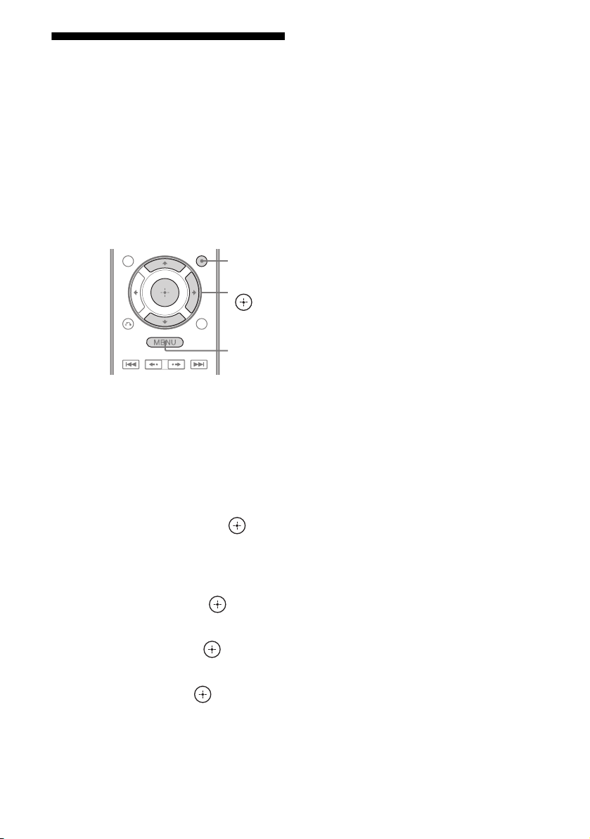
Enjoying the TV sound via
an HDMI cable
(Audio Return Channel)
The Audio Return Channel (ARC) function
enables the TV outputs the audio signals to the
receiver via an HDMI cable connected to the
HDMI TV OUT jack.
You can enjoy the TV sound from the speakers
connected to the receiver without connecting
the TV AUDIO IN or TV OPTICAL IN jack.
GUI
MODE
V/v/b,
MENU
1 Press GUI MODE.
After “MENU ON” appears on the
display for a while, “GUI” appears and
the GUI menu appears on the TV screen.
Press MENU if the GUI menu does not
appear on the TV screen.
Notes
• This function does not work when you set “Ctrl for
HDMI” to “OFF” in the HDMI Settings menu.
• This function is only available when
– your TV is compatible with Audio Return
Channel (ARC) function.
– INPUT MODE is set to “AUTO”.
2 Press V/v repeatedly to select
“Settings”, then press or b.
The Settings menu list appears on the TV
screen.
3 Press V/v repeatedly to select
“HDMI”, then press or b.
4 Press V/v repeatedly to select
“ARC”, then press or b.
5 Press V/v repeatedly to select
“ON”, then press .
GB
74
Page 75

S-AIR Operations
About S-AIR products
Room B
S-AIR sub unit
(S-AIR receiver)
This receiver is compatible with the S-AIR
function (page 119), which allows wireless
sound transmission between S-AIR products.
There are two types of S-AIR product.
• S-AIR main unit (this receiver):
The S-AIR main unit is for transmitting
sound.
You can use up to 3 S-AIR main units. (The
number of usable S-AIR main unit depends
on the use environment.)
• S-AIR sub unit (not supplied):
The S-AIR sub unit is for receiving sound.
– Surround amplifier: You can enjoy
surround and surround back speakers
sound wirelessly. For details, refer to the
operating instructions supplied with the
surround amplifier.
– S-AIR receiver: You can enjoy system
sound in another room.
These S-AIR products can be purchased as an
option (the S-AIR product lineup differs
depending on the area).
See the notes or instructions for the S-AIR sub
unit in this manual only when the S-AIR sub
unit is used.
Notes
• The S-AIR menu and parameters only available
when you have inserted the wireless transmitter.
• When the speaker pattern is set to a setting with
front high speakers, the surround back speakers
sound is not output from surround amplifier even if
the surround amplifier is used.
Room A
S-AIR main unit
(this receiver)
S-AIR sub unit
(surround amplifier)
S-AIR Operations
75
GB
Page 76

About environments where
S-AIR products (S-AIR main unit
and sub unit) are used
Setting up an S-AIR product
S-AIR products use a radio frequency of
2.4 GHz. Certain electronic equipment or
other factors may cause lost connection or
instability in S-AIR reception.
• Electronic equipment influence
The following may cause interference or
cross talk.
– Cellular phones, cordless phones
– Wireless LAN, personal computers
– Game machines using radio signals
–Microwave ovens
• Other factors
The following may cause poor reception.
– Materials or structures, such as walls and
floors
– The location where an S-AIR product is
placed
When using S-AIR products, place them as
far as possible from the above electronic
equipment, or place where S-AIR reception
is stable.
Before using an S-AIR product, be sure to
perform the following settings to establish the
sound transmission.
• Inserting the wireless transmitter/transceiver
(page 35).
• Establishing sound transmission between
the S-AIR main unit and S-AIR sub unit (ID
setting) (page 77).
• Pairing the S-AIR main unit with a specific
S-AIR sub unit (Pairing operation)
(page 78).
GUI MODE
V/v/b,
RETURN/
EXIT O
MENU
76
GB
Page 77

Establishing sound transmission
between the S-AIR main unit and
S-AIR sub unit (ID setting)
When you match the ID of the S-AIR main
unit and the S-AIR sub unit, you can establish
sound transmission. You can use multiple
S-AIR main unit by setting a different ID for
each unit.
8 Set the S-AIR sub unit to the same ID.
Sound transmission is established as
follows (example):
S-AIR main unit (this receiver)
ID A
To set the ID of the S-AIR main
unit
1
Press GUI MODE.
After “MENU ON” appears on the display
for a while, “GUI” appears and the GUI
menu appears on the TV screen.
Press MENU if the GUI menu does not
appear on the TV screen.
2 Press V/v repeatedly to select
“Settings”, then press or b.
The Settings menu list appears on the TV
screen.
3 Press V/v repeatedly to select “S-AIR”,
then press or b.
Note
When the S-AIR transmitter (not supplied) is not
inserted into the S-AIR main unit, “S-AIR”
cannot be selected.
4 Press V/v repeatedly to select “S-AIR
ID”, then press or b.
The S-AIR ID menu appears.
5 Press V/v repeatedly to select the ID
(A, B or C) you want, then press .
The ID of the S-AIR main unit is set. “Set
S-AIR ID of the sub unit to the same as that
of the main unit” appears.
6 Press .
ID A
S-AIR sub unit S-AIR sub unit
Tip
To confirm the current ID, performs steps 1 to 3
above. When you pair the S-AIR main unit with
the S-AIR sub unit (page 78), “(Pairing)”
appears beside the ID on the TV screen in the
GUI menu.
ID A
To exit the menu
Press MENU.
To set the ID of the S-AIR sub
unit
Be sure to match the ID on S-AIR sub unit you
want to the S-AIR main unit.
For details on setting the ID of the surround
amplifier and S-AIR receiver, refer to the
operating instructions supplied with the
surround amplifier and S-AIR receiver.
S-AIR Operations
7 Press GUI MODE.
The GUI menu turns off.
continued
77
GB
Page 78

To use multiple S-AIR main
units
You can use multiple S-AIR main units by
setting a different ID for each component.
Sound transmission is established as follows
(example):
S-AIR main unit
(this receiver)
Other S-AIR main
unit
ID A ID B
x Before pairing
Sound transmission is established by the ID
(example).
Your room
S-AIR main unit
(this receiver)
ID A
Neighbor
ID A ID A ID B
S-AIR sub
unit
S-AIR sub
unit
S-AIR sub unit
Notes
• Sources with copyright protection may not be
playable on S-AIR sub unit.
• If you have connected surround amplifier,
surround sound will not be output from S-AIR
main unit.
Pairing the S-AIR main unit with
a specific S-AIR sub unit
(Pairing operation)
To establish sound transmission, you need to
set the same ID for your S-AIR main unit and
S-AIR sub unit.
However, if your neighbors have S-AIR
products and their IDs are the same as yours,
your neighbors could receive the sound of
your S-AIR main unit or vice versa.
To prevent this, you can pair the S-AIR main
unit with a specific S-AIR sub unit by
performing the pairing operation.
ID A
S-AIR sub unit S-AIR sub unit
ID A
x After pairing
Sound transmission is established between the
paired S-AIR main unit and S-AIR sub unit(s)
only.
Your room
S-AIR main unit
(this receiver)
ID A ID A
S-AIR sub unit S-AIR sub unit
Pairing
Neighbor
No transmission
78
GB
Page 79

To perform pairing
1 Place the S-AIR sub unit that
you want to pair near the S-AIR
main unit.
2 Match the IDs of the S-AIR main
unit and the S-AIR sub unit.
• To set the ID of the S-AIR main unit,
see “To set the ID of the S-AIR main
unit” (page 77).
• To set the ID of the S-AIR sub unit,
refer to the operating instructions
supplied with the S-AIR sub unit.
3 Press GUI MODE.
After “MENU ON” appears on the
display for a while, “GUI” appears and
the GUI menu appears on the TV screen.
Press MENU if the GUI menu does not
appear on the TV screen.
4 Press V/v repeatedly to select
“Settings”, then press or b.
The Settings menu list appears on the TV
screen.
5 Press V/v repeatedly to select
“S-AIR”, then press or b.
Note
When the S-AIR transmitter (not supplied) is
not inserted into the S-AIR main unit, “S-AIR”
cannot be selected.
6 Press V/v repeatedly to select
“Pairing”, then press or b.
“Put the S-AIR sub unit near the S-AIR
main unit. Turn on power and start
pairing.” appears on the TV screen. The
S-AIR main unit is ready to start pairing.
7 Press B/b repeatedly to select
“Yes”, then press .
The S-AIR main unit starts pairing.
“Pairing. Do the pairing operation with
the S-AIR sub unit.” appears.
8 Start pairing of the S-AIR sub
unit.
Refer to the operating instructions of the
S-AIR sub unit.
Notes
• Perform pairing within 5 minutes in step 7. If
you do not, pairing is recognized as failed,
and the screen changes accordingly. In this
case, see “If pairing fails” (page 79).
• When sound transmission is established,
“Pairing complete. To do the pairing another
one, select “Continue”.” appears.
9 Press B/b repeatedly to select
“Finish” or “Continue”, then
press .
• “Finish”: Finishes pairing.
• “Continue”: Continues to perform
pairing to another S-AIR sub unit.
Tip
You can confirm the pairing completion or the
current ID by checking the “S-AIR Settings”
screen. “Pairing” appears beside the current
S-AIR ID.
10Press GUI MODE.
The GUI menu turns off.
Note
After you have performed pairing, if you select
the “S-AIR ID” menu, the ID setting (“A”, “B”
or “C”) that you last used is displayed.
If pairing fails
“Pairing failed. Retry?” appears.
To perform pairing again, select “Yes”.
To finish pairing, select “No”.
To quit pairing during setting
Press RETURN/EXIT O.
To cancel pairing
Perform the ID setting of the main unit
according to the procedure of “To set the ID of
the S-AIR main unit” (page 77). If you reset
the ID (even the same ID again), pairing is
canceled.
S-AIR Operations
79
GB
Page 80

Enjoying the system’s sound in another room
(For the S-AIR receiver only (not
supplied))
You can enjoy the system’s sound in another
room by using the S-AIR receiver. The S-AIR
receiver can be placed in another room for
enjoying the system’s sound there.
For details of the S-AIR receiver, refer to the
operating instructions supplied with the S-AIR
receiver.
2 Press GUI MODE.
After “MENU ON” appears on the
display for a while, “GUI” appears and
the GUI menu appears on the TV screen.
Press MENU if the GUI menu does not
appear on the TV screen.
3 Press V/v repeatedly to select
“Settings”, then press or b.
The Settings menu list appears on the TV
screen.
4 Press V/v repeatedly to select
“S-AIR”, then press or b.
GUI MODE
V/v/b,
MENU
1 Set the ID of the S-AIR receiver
to match the ID of the S-AIR
main unit.
• To set the ID of the S-AIR main unit,
see “To set the ID of the S-AIR main
unit” (page 77).
• To set the ID of the S-AIR receiver,
refer to the operating instructions
supplied with the S-AIR receiver.
Notes
• When you are using another S-AIR sub unit,
such as a surround amplifier, do not change
the ID of the S-AIR main unit. Set the ID of
the S-AIR receiver to match the ID of the
S-AIR main unit.
• When you pair the S-AIR main unit and
another S-AIR sub unit, such as a surround
amplifier, you also need to pair the S-AIR
main unit and the S-AIR receiver. For details,
see “Pairing the S-AIR main unit with a
specific S-AIR sub unit (Pairing operation)”
(page 78).
Note
When the S-AIR transmitter (not supplied) is
not inserted into the S-AIR main unit, “S-AIR”
cannot be selected.
5 Press V/v repeatedly to select
“S-AIR Mode”, then press
or b.
6 Press V/v repeatedly to select
the setting you want, then
press .
• Party: The S-AIR receiver outputs
sound according to the input selected on
the S-AIR main unit.
• Separate: You can select the input you
want for the S-AIR receiver while the
input of the S-AIR main unit remain
unchanged. When “Separate” is
selected, you can only select “SA-CD/
CD”, “DMPORT”, “FM TUNER”,
“AM TUNER”, “SIRIUS”* and the
input that is currently selected on the
S-AIR main unit.
Note
When the input selected on the S-AIR
receiver is same as S-AIR main unit, the
input of the S-AIR receiver will change
according to the S-AIR main unit.
7 Press GUI MODE.
The GUI menu turns off.
80
GB
Page 81

8 Select the desired input on the
S-AIR receiver.
xWhen “Party” is set
The S-AIR receiver’s input changes
sequentially as you change the input on
the S-AIR main unit or S-AIR receiver.
xWhen “Separate” is set
The S-AIR receiver’s input changes by
pressing S-AIR CH of the S-AIR
receiver.
Note
When TUNER (FM/AM band) is selected on
the S-AIR main unit, you can only select the
same band for the tuner on the S-AIR receiver.
However, you can select input other than
TUNER on the S-AIR receiver.
9 Adjust the volume on the S-AIR
receiver.
* Models of area code U2, CA2 only.
Notes
• The sound of the S-AIR receiver may be cut off by
operation of the S-AIR main unit.
• When the sound is other than 2 channel stereo,
multi channel sound is downmixed to 2 channel.
• Signals with a sampling frequency of more than
96 kHz cannot output to the S-AIR receiver.
To control the system from the
S-AIR receiver
You can control the system from the S-AIR
receiver by using the following buttons.
Press Operation
N, X, x,
./>
S-AIR CH Change the function of the
For details, refer to the operating instructions
of the S-AIR receiver.
Share the same operations on the
remote
system
Changing the channel for better sound transmission
If you use multiple wireless systems which
share the 2.4 GHz band, such as wireless LAN
or Bluetooth, the transmission of S-AIR
products or other wireless systems may be
unstable. In this case, transmission may be
improved by changing the “RF Change”
setting.
GUI MODE
V/v/b,
MENU
1 Press GUI MODE.
After “MENU ON” appears on the
display for a while, “GUI” appears and
the GUI menu appears on the TV screen.
Press MENU if the GUI menu does not
appear on the TV screen.
2 Press V/v repeatedly to select
“Settings”, then press or b.
The Settings menu list appears on the TV
screen.
3 Press V/v repeatedly to select
“S-AIR”, then press or b.
Note
When the S-AIR transmitter (not supplied) is
not inserted into the S-AIR main unit, “S-AIR”
cannot be selected.
S-AIR Operations
continued
81
GB
Page 82

4 Press V/v repeatedly to select
“RF Change”, then press or
b.
5 Press V/v repeatedly to select
the setting you want, then
press .
• AUTO: Normally select this. The
system changes “RF Change” to “ON”
or “OFF” automatically.
• ON: The system transmits sound by
searching for a better channel for
transmitting.
• OFF: The system transmits sound by
fixing the channel for transmitting.
6 Press GUI MODE.
The GUI menu turns off.
7 When you set “RF Change” to
“OFF”, select the ID so that
sound transmission is most
stable.
Notes
• In most cases, you will not need to change this
setting.
• If “RF Change” is set to “OFF”, transmission
between the S-AIR main unit and S-AIR sub unit
can be performed using one of the following
channels.
– S-AIR ID A: equivalent channel for IEEE
802.11b/g channel 1
– S-AIR ID B: equivalent channel for IEEE
802.11b/g channel 6
– S-AIR ID C: equivalent channel for IEEE
802.11b/g channel 11
• The transmission may be improved by changing
the transmission channel (frequency) of the other
wireless system(s). For details, refer to the
operating instructions of the other wireless
system(s).
Stabilizing S-AIR reception
Check the following when S-AIR reception is
poor or unstable.
– Confirm the wireless adapters are inserted
correctly (page 35).
– Confirm that the S-AIR IDs of the S-AIR
main unit and sub unit are the same
(page 77).
When S-AIR reception is poor
Check the following.
• Keep cords that are connected to the S-AIR
product (AC power cord (mains lead),
speaker cords, or other cords) away from the
wireless adapter and slot.
• Keep as much space as possible around
S-AIR products.
– Avoid placing S-AIR products on top of or
directly below other electronic equipment.
– Avoid placing S-AIR products in a closed
rack, metal rack or under a table.
82
GB
Page 83

• Adjust the location (height, orientation, and
place in the room) of S-AIR products until
reception is the most stable.
– Place so that the wireless adapters of the
S-AIR main unit and sub unit are closer.
Enjoying the S-AIR receiver while the S-AIR main unit is in standby mode
(For the S-AIR receiver only (not
supplied))
You can enjoy the S-AIR receiver while the
S-AIR main unit is in standby mode by setting
“S-AIR Stby” to “ON”.
– Place so that S-AIR products are separated
from other wireless devices.
– Place so that S-AIR products are separated
from metal doors or tables.
If you still cannot improve S-AIR reception,
change the “RF Change” setting (page 81).
GUI MODE
V/v/b,
MENU
1 Press GUI MODE.
After “MENU ON” appears on the
display for a while, “GUI” appears and
the GUI menu appears on the TV screen.
Press MENU if the GUI menu does not
appear on the TV screen.
2 Press V/v repeatedly to select
“Settings”, then press or b.
The Settings menu list appears on the TV
screen.
3 Press V/v repeatedly to select
“S-AIR”, then press or b.
Note
When the S-AIR transmitter (not supplied) is
not inserted into the S-AIR main unit, “S-AIR”
cannot be selected.
S-AIR Operations
4 Press V/v repeatedly to select
“S-AIR Stby”, then press or
b.
continued
83
GB
Page 84

5 Press V/v repeatedly to select
the setting you want.
• ON: You can enjoy the S-AIR receiver
while the S-AIR main unit is in standby
mode or turned on.
• OFF: You cannot enjoy the S-AIR
receiver while the S-AIR main unit is in
standby mode.
Advanced Operations
Switching between
digital and analog audio
(INPUT MODE)
To exit the menu
Press MENU.
Notes
• When you set “S-AIR Stby” to “ON”, the power
consumption increases during the standby mode.
• When the wireless transmitter is removed from the
S-AIR main unit, “S-AIR Stby” is set to “OFF”
automatically.
• If you have selected TUNER (FM/AM band) on
the S-AIR main unit before you turn it off and
“S-AIR Stby” is set to “ON”, you can only select
the same band for the tuner on the S-AIR receiver.
However, you can select input other than TUNER
on the S-AIR receiver.
• The sound of the S-AIR receiver may be cut off by
operation of the S-AIR main unit.
• When the receiver is in standby mode,
“A.STANDBY” appears on the display if “S-AIR
Stby” is set to “ON”.
When you connect components to both digital
and analog audio input jacks on the receiver,
you can fix the audio input mode to either of
them, or switch from one to the other,
depending on the type of material you intend
to watch.
1 Press INPUT SELECTOR +/– on
the receiver to select the input.
You can also use the input buttons on the
remote.
2 Press INPUT MODE repeatedly
on the receiver to select the
audio input mode.
The selected audio input mode appears on
the display.
Audio input modes
x AUTO
Gives priority to digital audio signals when
there are both digital and analog connections.
If there are no digital audio signals, analog
audio signals are selected.
84
x ANALOG
Specifies the analog audio signals input to the
AUDIO IN (L/R) jacks.
GB
Page 85

Notes
• Some audio input modes may not be set up
depending on the input.
• When either the HDMI 1-4 input, DMPORT input
or SIRIUS* is selected, “------” appears on the
display, and you cannot select other modes. Select
an input mode other than the HDMI 1-4 input,
DMPORT input or SIRIUS* then set the audio
input mode.
• When “Analog Direct” is being used, audio input is
automatically set to “ANALOG”. You cannot
select other modes.
* Models of area code U2, CA2 only.
Enjoying the sound/ images from other inputs
You can reassign audio and/or video signals to
another input when they are not currently
being used.
For example when you want to connect your
DVD player but cannot find an unused input:
DVD player
To OP TI CAL
BD IN jack
(audio signal)
To COMPONENT
VIDEO IN 1 jacks
(video signal)
Receiver
Assign to DVD input jack
using “Input Assign” in
the Input Option menu.
1 Press GUI MODE.
After “MENU ON” appears on the
display for a while, “GUI” appears and
the GUI menu appears on the TV screen.
Press MENU if the GUI menu does not
appear on the TV screen.
2 Press V/v repeatedly to select
“Input”, then press or b.
BD
Input
DVD
SAT/CATV
TV
VIDEO 1
Advanced Operations
3 Press V/v repeatedly to select
the input name you want to
assign.
continued
85
GB
Page 86

4 Press TOOLS/OPTIONS.
BD
Input
DVD
SAT/CATV
TV
VIDEO 1
Input Assign
Name lnput
5 Press V/v repeatedly to select
“Input Assign”, then press
or b.
The “Input Assign” screen appears.
6 Select the audio and/or video
signals you want to assign to
the input which you selected in
step 3 using V/v/B/b.
Input Assign
Select Video Select Audio
COMP.2
COMP.3
CVBS
SAT OPT
DVD C OAX
ANALOG
RETURN
7 Press to enter the setting.
GB
86
Page 87

Input name
Assignable
video input
jacks
Assignable
audio input
jacks
* Initial setting
COMP.1 a* aaaaa
COMP.2 aa* aaaa
COMP.3 aaa* aaa
CVBS a – aa* a*–
HDMI1 aaaaaa
HDMI2 aaaaaa
HDMI3 aaaaaa
HDMI4 aaaaaa
NONE – a –––a*
BD OPT a* a – aaa
SAT OPT – aa* aaa
DVD COAX aa* aaaa
ANALOG a – aa* a* a*
BD DVD SAT/CATV VIDEO 1 VIDEO 2 SA-CD/CD/
Notes
• You cannot assign optical signals from an input
source to the optical input jacks on the receiver.
• When you assign the digital audio input, the
INPUT MODE setting may change automatically.
• You cannot reassign more than one HDMI input to
the same input.
• You cannot reassign more than one digital audio
input to the same input.
• You cannot reassign more than one component
video input to the same input.
CD-R
Advanced Operations
87
GB
Page 88

Using a bi-amplifier connection
1
Press GUI MODE.
After “MENU ON” appears on the
display for a while, “GUI” appears and
the GUI menu appears on the TV screen.
Press MENU if the GUI menu does not
appear on the TV screen.
2 Press V/v repeatedly to select
“Settings” then press or b.
The Settings menu list appears on the TV
screen.
3 Press V/v repeatedly to select
“Speaker”, then press or b.
4 Press V/v repeatedly to select
“SP Pattern”, then press or
b.
5 Press V/v repeatedly to select
the appropriate speaker pattern
so that there are no surround
back speakers and front high
speakers, then press .
Notes
• Set “SB Assign” to “BI-AMP” before you perform
Auto Calibration.
• If you set “SB Assign” to “BI-AMP”, the speaker
level and distance settings of the surround back
speakers and front high speakers become invalid,
and those of the front speakers are used.
• If you set “SP Pattern” to a setting with surround
back speakers or front high speakers, you cannot
set “SB Assign” to “BI-AMP”.
6 Press V/v repeatedly to select
“SB Assign”, then press or
b.
7 Press V/v repeatedly to select
“BI-AMP”, then press .
The same signals output from the
SPEAKERS FRONT A terminals can be
output from the SPEAKERS
SURROUND BACK/FRONT HIGH/
BI-AMP/FRONT B terminals.
To exit the menu
Press MENU.
GB
88
Page 89

Using the setting menu
You can adjust various settings for speakers,
surround effects, etc. using the setting menu.
To display the menu of the receiver on the TV
screen, make sure that the receiver is in “GUI
MODE” by following the steps in “To turn
“GUI MODE” on and off” (page 44).
GUI MODE
V/v/b,
2 Press V/v repeatedly to select
“Settings”, then press or b
to enter the menu mode.
The Setting menu list appears on the TV
screen.
Auto Cal.
AM
AM
Speaker
SR
Surround
SR
EQ
Settings
Audio
RETURN/
EXIT O
1 Press GUI MODE.
After “MENU ON” appears on the
display for a while, “GUI” appears and
the GUI menu appears on the TV screen.
Press MENU if the GUI menu does not
appear on the TV screen.
BD
Input
Music
Video
DVD
SAT/CATV
TV
VIDEO 1
MENU
3 Press V/v repeatedly to select
the menu item you want, then
press or b.
Example: When you select “Auto Cal.”.
Auto Cal.
Speaker
Surround
EQ
Settings
Audio
4 Press V/v repeatedly to select
the parameter you want, then
press or b.
To return to the previous screen
Press RETURN/EXIT O.
To exit the menu
Press MENU.
Advanced Operations
Note
appears for models of area code U2, CA2 only.
SR
continued
89
GB
Page 90

Setting menu list
Menu Description
Auto Cal. Sets the speaker level or
distance and makes the
measurement automatically
(page 90).
Speaker Sets the speaker position
manually (page 91).
Surround Adjusts the sound field
(surround effect) you choose
(page 95).
EQ Adjusts the equalizer (bass/
treble sound) (page 96).
Audio Sets various sound items
(page 96).
Video Adjusts the resolution of
analog video signals (page
97).
HDMI Makes settings for sound/
images from components
connected to the HDMI jacks
(page 98).
System Sets the receiver switch to
standby mode automatically
(page 100).
S-AIR Makes settings for S-AIR
operations (page 75).
Auto Calibration menu
You can make settings for the Auto
Calibration function to suit your preference.
Auto Cal. Start (Auto Calibration
start)
Lets you perform Auto Calibration. For
details, see “2: Performing Auto Calibration”
(page 40).
Auto Cal. Type (Auto Calibration
type)
Lets you select the Auto Calibration type for
each seating position. For details, see step 4 of
“3: Confirming/saving the measurement
results” (page 41).
Note
You can select this parameter only when you have
performed the Auto Calibration and saved the
measurement result.
90
Position
You can register 3 patterns as Position 1, 2,
and 3, depending on the listening position,
listening environment, and measurement
conditions.
GB
Page 91

To register settings for the
listening environment
You can select the seating position you want
and register the measurement results of the
Auto Calibration for that seating position.
1 Press V/v repeatedly to select
“Position”, then press or b.
2 Press V/v repeatedly to select the
position (Position 1, 2, 3) for which you
want to register the measurement
result, then press .
3 Press V/v repeatedly to select “Auto
Cal. Start”, then press or b.
The measurement results is registered as
the position you selected in step 2.
4 Press to select “START”.
5 Repeat step 1 to 3 to register another
seating position.
To select the registered seating
position
1
Press V/v repeatedly to select
“Position”, then press or b.
Speaker Settings menu
You can adjust each speaker manually.
You can also adjust the speaker levels after the
Auto Calibration is completed.
Note
The speaker settings are only for the current seating
position.
SP Pattern (Speaker pattern)
Select “SP Pattern” according to the speaker
system which you are using. You do not need
to select the speaker pattern after Auto
Calibration.
1 Press V/v repeatedly to select
“SP Pattern”, then press or b.
The “SP Pattern” screen appears.
2 Press V/v repeatedly to select the
speaker pattern you want, then press
.
3 Press RETURN/EXIT O.
2 Press V/v repeatedly to select the
position (Position 1, 2, 3) you want,
then press .
The registered seating position is selected.
Name Input (Naming position)
You can rename the position name.
1 Select the “Position” for which you want
to name.
2 Press V/v repeatedly to select “Name
Input”, then press or b.
3 Press V/v/B/b to select a character,
then press .
The name you entered is registered.
SB Assign (Surround back
speaker assign)
You can make settings for the surround back
speaker(s) or front high speaker(s). Before you
change “SB Assign” to “BI-AMP” or
“Speaker B”, be sure you have set “SP
Pattern” to a setting without surround back
speakers or front high speakers.
• Speaker B
If you connect an additional front speaker
system to the SPEAKERS SURROUND
BACK/FRONT HIGH/BI-AMP/FRONT B
terminals, select “Speaker B”.
• BI-AMP
If you connect front speakers to the
SPEAKERS SURROUND BACK/FRONT
HIGH/BI-AMP/FRONT B terminals using a
bi-amplifier connection, select “BI-AMP”.
continued
91
Advanced Operations
GB
Page 92

•OFF
If you do not use “Speaker B” or “BI-AMP”,
select “OFF”.
Note
Set “SB Assign” to “OFF”, then connect the
surround back speakers to this receiver when you
want to change the connection from a bi-amplifier
connection or speakers front B connection to a
surround back speakers connection. Re-set up the
speakers after you connect the surround back
speakers. See “Calibrating the appropriate speaker
settings automatically (Auto Calibration)”
(page 38).
Manual Setup
You can adjust each speaker manually on the
“Manual Setup” screen. You can also adjust
the speaker levels after the Auto Calibration is
completed.
To adjust the speaker level
You can adjust each speaker’s level (front left/
right, front left/right high, center, surround
left/right, surround back left/right,
subwoofer).
1 Press V/v/B/b repeatedly to select the
speaker on the screen for which you
want to adjust the level, then press .
2 Press B/b repeatedly to select “Lvl:”.
3 Press V/v repeatedly to set the level of
the selected speaker, then press .
For front left/right speakers, you can adjust
the level from –10.0 dB to +10.0 dB in
0.5 dB steps. For other speakers, you can
adjust the level from –20.0 dB to +10.0 dB
in 0.5 dB steps.
To adjust the distance from the
seating position to each
speaker
You can adjust the distance from the listening
position to each speaker (front left/right, front
left/right high, center, surround left/right,
surround back left/right, subwoofer).
1 Press V/v/B/b repeatedly to select the
speaker on the screen for which you
want to adjust the distance from the
seating position, then press .
2 Press B/b repeatedly to select “Dist:”.
3 Press V/v repeatedly to set the
distance of the selected speaker, then
press .
You can adjust the distance from 3 feet
3 inches to 32 feet 9 inches (1.00 meter to
10.00 meters) in 1 inch (0.01 meter) steps.
Notes
• Depending on the speaker pattern setting, some
parameters may not be available.
• This function does not work in the following cases.
– Sound Field is set to “Analog Direct”.
– Signals with a sampling frequency of more than
96 kHz are being received.
To adjust the size of each
speaker
You can adjust each speaker’s (front left/right,
front left/right high, center, surround left/right,
surround back left/right) size.
1 Press V/v/B/b repeatedly to select the
speaker on the screen for which you
want to adjust the size, then press .
2 Press B/b repeatedly to select “Size:”.
Note
When one of the sound fields for music is selected,
no sound is output from the subwoofer if all the
speakers are set to “Large”. However, the sound will
be output from the subwoofer if
– the digital input signal contains LFE signals.
– the front or surround speakers are set to “Small”.
– the sound field for movie is selected.
– “Portable Audio” is selected.
GB
92
Page 93

3 Press V/v repeatedly to set the size of
the selected speaker, then press .
•Large
If you connect large speakers that will
effectively reproduce bass frequencies,
select “Large”. Normally, select “Large”.
• Small
If the sound is distorted, or you feel a lack
of surround effects when using multi
channel surround sound, select “Small” to
activate the bass redirection circuitry and
output the bass frequencies of each
channel from the subwoofer or other
“Large” speakers.
Note
This function does not work when “Analog Direct”
is being used.
Tips
• The “Large” and “Small” settings for each speaker
determine whether the internal sound processor
will cut the bass signal from that channel.
When the bass is cut from a channel, the bass
redirection circuitry sends the corresponding bass
frequencies to the subwoofer or other “Large”
speakers.
However, since bass sound has a certain amount of
directionality, it is best not to cut it, if possible.
Therefore, even when using small speakers, you
can set them to “Large” if you want to output the
bass frequencies from that speaker. On the other
hand, if you are using a large speaker, but prefer
not to have bass frequencies output from that
speaker, set it to “Small”.
If the overall sound level is lower than you prefer,
set all speakers to “Large”. If there is not enough
bass, you can use the equalizer to boost the bass
levels.
• The surround back speakers will be set to the same
setting as that of the surround speakers.
• When the front speakers are set to “Small”, the
center, surround, and front high speakers are also
automatically set to “Small”.
• If you do not use the subwoofer, the front speakers
are automatically set to “Large”.
Crossover Frequency (Speaker
crossover frequency)
Lets you set the bass crossover frequency of
speakers that the speaker size has been set to
“Small” in the Speaker Settings menu.
Measured speaker crossover frequency is set
for each speaker after the Auto Calibration.
1 Press V/v repeatedly to select
the speaker on the screen you
want to adjust, then press .
2 Press V/v repeatedly to adjust
the value, then press .
Test Tone
You can select the test tone type on the “Test
Tone” screen.
Tips
• To adjust the level of all speakers at the same time,
press MASTER VOL +/–. You can also use
MASTER VOLUME on the receiver.
• The adjusted value is shown on the TV screen
during adjustment.
To output test tone from each
speaker
You can output test tone from the speakers in
sequence.
1 Press B/b repeatedly to select “Test
Tone”, then press .
2 Press V/v repeatedly to adjust the
parameter, then press .
•OFF
• AUTO
The test tone is output from each speaker
in sequence.
• FL, CNT, FR, SR, SB, SBR, SBL, SL,
LH, RH, SW
You can select which speakers will output
the test tone.
3 Press V/v repeatedly to adjust the
speaker level, then press .
continued
93
Advanced Operations
GB
Page 94

To output test tone from
adjacent speakers
You can output test tone from adjacent
speakers so that you can adjust the balance
between the speakers.
1 Press B/b repeatedly to select “Phase
Noise”, then press .
2 Press V/v repeatedly to adjust the
parameter, then press .
•OFF
• LH/FR, LH/RH, FL/RH, FL/SR, SL/FL,
SB/SL, SBL/SL, SBR/SBL, SR/SB,
SR/SBR, SR/SL, FR/SR, FR/SL,
CNT/FR, FL/CNT
Lets you output the test tone sequentially
from adjacent speakers.
Some items may not be displayed,
depending on the setting of the speaker
pattern.
3 Press V/v repeatedly to adjust the
speaker level, then press .
To output the source sound
from adjacent speakers
You can output the source sound from
adjacent speakers so that you can adjust the
balance between the speakers.
1 Press B/b repeatedly to select “Phase
Audio”, then press .
2 Press V/v repeatedly to adjust the
parameter, then press .
•OFF
• LH/FR, LH/RH, FL/RH, FL/SR, SL/FL,
SB/SL, SBL/SL, SBR/SBL, SR/SB,
SR/SBR, SR/SL, FR/SR, FR/SL,
CNT/FR, FL/CNT
Lets you output front 2 channel source
sound (instead of the test tone)
sequentially from adjacent speakers.
Some items may not be displayed,
depending on the setting of the speaker
pattern.
When a test tone is not output
from the speakers
• The speaker cords may not be connected
securely. Check to see if they are connected
securely and cannot be disconnected by
pulling on them slightly.
• The speaker cords may have the short-circuit
problem.
When a test tone is output from
a different speaker than the
speaker displayed on the TV
screen
The speaker pattern to the connected speaker
is not set up correctly. Make sure the speaker
connection and the speaker pattern match.
D.Range Comp (Dynamic range
compression)
Lets you compress the dynamic range of the
soundtrack. This may be useful when you want
to watch movies at low volumes late at night.
Dynamic range compression is possible with
Dolby Digital sources only.
x MAX
The dynamic range is compressed
dramatically.
x STD
The dynamic range is compressed as intended
by the recording engineer.
x AUTO
The dynamic range is applied automatically
with Dolby TrueHD source or other source is
set to “OFF”.
x OFF
The dynamic range is not compressed.
3 Press V/v repeatedly to adjust the
speaker level, then press .
GB
94
Page 95

Tips
• Dynamic range compressor lets you compress the
dynamic range of the soundtrack based on the
dynamic range information included in the Dolby
Digital signal.
• “STD” is the standard setting, but it only enacts
light compression. Therefore, we recommend
using the “MAX” setting. This greatly compresses
the dynamic range and lets you view movies late at
night at low volumes. Unlike analog limiters, the
levels are predetermined and provide a very natural
compression.
Distance Unit
Lets you select the unit of measure for setting
distances.
x FEET
The distance is displayed in feet.
x METER
The distance is displayed in meters.
Surround Settings menu
You can adjust the sound effect on the
“S.F. Select” screen.
Note
The setup items you can adjust on each menu vary
depending on the sound field.
S.F. Select (Sound field select)
You can select the surround sound field and
adjust the effect level on the “S.F. Select”
screen.
For details on the sound field, see “Enjoying
Surround Sound” (page 65).
To select the surround sound
field
1
Press V/v repeatedly to select
“S.F. Select”, then press or b.
2 Press V/v repeatedly to select
surround sound you want, then press
.
To adjust the effect level
1
Press V/v repeatedly to select
“S.F. Select”, then press or b.
2 Press V/v repeatedly to select
surround sound you want, then press
or b.
Note
Effect Level adjustment is valid only when
“Cinema St EX DCS ” is selected.
3 Press V/v repeatedly to select effect
level you want, then press .
•MAX
•STD
•MIN
95
Advanced Operations
GB
Page 96

EQ Settings menu
Audio Settings menu
You can use the following parameters to adjust
the tonal quality (bass/trebel level) of front
speakers.
Bass Treble
Level
(dB)
Frequency
(Hz)
Notes
• This function does not work in the following cases.
– Sound Field is set to “Analog Direct”.
– Signals with a sampling frequency of more than
48 kHz are being received.
• If the equalizer is adjusted while the receiver is
receiving signals with a sampling frequency of
more than 96 kHz, the signals will always be
played back at 96 kHz.
To adjust the equalizer on the
EQ screen
1
Press B/b repeatedly to select “Bass”
or “Treble”.
2 Press V/v repeatedly to adjust the gain,
then press .
You can make settings for the audio to suit
your preference.
A/V Sync (Synchronizes audio
with video output)
Lets you delay the output of audio to minimize
the time gap between audio output and visual
display. You can adjust the delay from 0 ms to
300 ms in 10 ms steps.
Notes
• This parameter is useful when you use a large LCD
or plasma monitor or a projector.
• This function does not work in the following cases.
– Sound Field is set to “Analog Direct”.
– Signals with a sampling frequency of more than
96 kHz are being received.
Dual Mono (Digital broadcast
language selection)
Lets you select the language you want to listen
to during digital broadcast. This feature only
functions for Dolby Digital sources.
x Main/Sub
Sound of the main language will be output
through the front left speaker and sound of the
sub language will be output through the front
right speaker simultaneously.
96
x Main
Sound of the main language will be output.
x Sub
Sound of the sub language will be output.
GB
Page 97

Dec. Priority (Digital audio input
decoding priority)
Lets you specify the input mode for the digital
signal input to the DIGITAL IN jacks or
HDMI IN jacks.
x AUTO
Automatically switches the input mode
between DTS, Dolby Digital, or PCM.
x PCM
When signals from the DIGITAL IN jack are
selected, PCM signals are given priority (to
prevent interruption when playback starts).
However, when other signals are input, there
may be no sound, depending on the format.
In this case, set this item to “AUTO”.
When signals from the HDMI IN jack are
selected, only PCM signals are output from the
connected player. When signals other than
PCM are received, set this item to “AUTO”.
Notes
• Even when “Dec. Priority” is set to “PCM”, the
sound may be interrupted at the very beginning of
the first track depending on the CD being played
back.
• When playback a DTS CD, set “Dec. Priority” to
“AUTO”.
Video Settings menu
You can make settings for video.
Resolution (Converting video
signals)
Lets you convert the resolution of analog video
input signals (component video and video) and
output from the HDMI TV OUT jack.
x AUTO
The resolution is set automatically, depending
on the connected TV.
x 480/576p
The resolution is set to 480p/576p. Video
signals are upconverted and output through the
receiver.
x 720p
The resolution is set to 720p. Video signals are
upconverted and output through the receiver.
x 1080i
The resolution is set to 1080i. Video signals
are upconverted and output through the
receiver.
Advanced Operations
x 1080p
The resolution is set to 1080p. Video signals
are upconverted and output through the
receiver.
Note
If you select a resolution that the connected TV does
not support in “Resolution” menu, the images from
the TV will not be output correctly.
97
GB
Page 98

Comp.Dec. (Component video
decoder)
If the image is distorted when you connect to
video game, set “Comp.Dec.” to “ON”. This
setting is only applicable for component video
input signals.
x ON
x OFF
HDMI Settings menu
You can make the required settings for
components connected to the HDMI jack.
Ctrl for HDMI (Control for HDMI)
Lets you turn the Control for HDMI function
on or off. For details, see “Preparing for the
“BRAVIA” Sync” (page 70).
x ON
x OFF
Note
When you set “Ctrl for HDMI” to “ON”, “Audio
Out” may be changed automatically.
Pass Through
Lets you output the HDMI signals to the TV
even when the receiver is in standby mode.
x ON
When the receiver is in the standby mode, the
receiver continuously outputs HDMI signals
from the receiver’s HDMI TV OUT jack.
98
x AUTO
When the TV is turned on while the receiver is
in the standby mode, the receiver outputs
HDMI signals from the receiver’s HDMI TV
OUT jack. Sony recommends this setting if
you use a TV that is compatible with
“BRAVIA” Sync. This setting saves power in
the standby mode compared with the “ON”
setting.
x OFF
The receiver does not output HDMI signals
when in the standby mode.
Turn on the receiver to enjoy the connected
component’s source on the TV. This setting
saves power in the standby mode compared
with the “ON” setting.
GB
Page 99

Notes
• This parameter is not available when “Ctrl for
HDMI” is set to “OFF”.
• When “AUTO” is selected, it may take a little more
time for the image and sound to be output to the TV
than when “ON” is selected.
• When the receiver is in standby mode,
“A.STANDBY” appears on the display if “Pass
Through” is set to “AUTO” or “ON”. However,
“A.STANDBY” will disappear when “Pass
Through” is set to “AUTO” and no signals are
detected.
Audio Out (Setting HDMI audio
input)
Lets you set the audio output for HDMI from
the playback component connected to the
receiver via an HDMI connection.
x AMP
The HDMI audio signals from the playback
component is only output to the speakers
connected to the receiver. Multi channel sound
can be played back as it is.
Note
Audio signals are not output from the TV speakers
when “Audio Out” is set to “AMP”.
x TV+AMP
The sound is output from TV’s speaker and the
speakers connected to the receiver.
Notes
• The sound quality of the playback component
depends on the TV’s sound quality, such as the
number of channels, and the sampling frequency,
etc. When the TV has stereo speakers, the sound
output from the receiver is also stereo as that of the
TV, even if you play back multi channel source.
• When you connect the receiver to an image display
component (projector, etc.), sound may not be
output from the receiver. In this case, select
“AMP”.
• When you select the input that you have assigned
the HDMI input, sound does not output from the
TV.
SW Level (Subwoofer level for
HDMI)
Lets you set the level of the subwoofer to 0 dB
or +10 dB when PCM signals are input via an
HDMI connection. You can set the level for
each HDMI input independently.
x AUTO
Automatically sets the level to 0 dB or +10 dB
depending on the frequency.
x +10 dB
x 0 dB
SW L.P.F. (Subwoofer Low Pass
Filter for HDMI)
Lets you set the low pass filter of the
subwoofer when multi channel Linear PCM
signals are input via an HDMI connection.
Set the “SW L.P.F.” if your connected
subwoofer’s crossover frequency do not have
low pass filter.
x ON
The low pass filter of the subwoofer’s cut off
frequency is set to 120 Hz.
x OFF
The low pass filter of the subwoofer is turned
off.
Advanced Operations
99
GB
Page 100

ARC (Audio Return Channel)
Lets you enjoy the TV sound from the
speakers connected to the receiver via an
HDMI cable. For details, see “Enjoying the
TV sound via an HDMI cable” (page 74).
x ON
Audio signal is input to the HDMI TV OUT
jack.
x OFF
Audio signal is input to the TV OPTICAL IN
or TV AUDIO IN jack.
Note
This parameter is not available when “Ctrl for
HDMI” is set to “OFF”.
System Settings menu
You can customize the settings of the receiver.
Auto Standby
Lets you set the receiver switch to standby
mode automatically when you do not operate
the receiver or when there is no signals input to
the receiver.
x ON
Switches to standby mode after approximately
30 minutes.
x OFF
Does not switch to standby mode.
Notes
• This function does not work in the following cases.
– TUNER input is selected.
– S-AIR receiver or surround amplifier is used.
• If you use the Auto standby mode and the Sleep
Timer at the same time, the Sleep Timer has
priority.
100
GB
 Loading...