

Sony STR-DH720,STR-DH720HP Service Manual
SERVICE MANUAL
Published by Sony EMCS (Malaysia) PG Tec
Sony Corporation
MULTI CHANNEL AV RECEIVER
US Model
STR-DH720/DH720HP
Canadian Model
AEP Model
STR-DH720
STR-DH720/DH720HP
Ver. 1.2 2011.10
9-890-560-03
2011J80-1
©
2011.10
AUDIO POWER SPECIFICATIONS
POWER OUTPUT AND TOTAL HARMONIC
DISTORTION:
(US model only)
With 8 ohm loads, both channels driven, from
20 – 20,000 Hz; rated 95 watts per channel
minimum RMS power, with no more than 0.09%
total harmonic distortion from 250 milliwatts to
rated output.
Amplifi er section
US model
1)
Minimum RMS Output Power
(8 ohms, 20 Hz – 20 kHz, THD 0.09%)
95 W + 95 W
Stereo Mode Output Power
(8 ohms, 1 kHz, THD 1%)
105 W + 105 W
Surround Mode Output Power
2)
(8 ohms, 1 kHz, THD 10%)
140 W per channel
CND model
1)
Minimum RMS Output Power
(8 ohms, 20 Hz – 20 kHz, THD 0.09%)
85 W + 85 W
Stereo Mode Output Power
(8 ohms, 1 kHz, THD 1%)
105 W + 105 W
Surround Mode Output Power
2)
(8 ohms, 1 kHz, THD 10%)
140 W per channel
ECE model
1)
Minimum RMS Output Power
(8 ohms, 20 Hz – 20 kHz, THD 0.09%)
85 W + 85 W
Stereo Mode Output Power
(8 ohms, 1 kHz, THD 1%)
100 W + 100 W
Surround Mode Output Power
2)
(8 ohms, 1 kHz, THD 10%)
140 W per channel
1)
Measured under the following conditions:
Area Power requirements
US, CND 120 V AC, 60 Hz
ECE 230 V AC, 50 Hz
2)
Reference power output for front, center, surround,
surround back and front high speakers. Depending
on the sound fi eld settings and the source, there
may be no sound output.
Frequency response
Analog 10 Hz – 70 kHz,
+0.5/–2 dB (with
sound fi eld and
equalizer bypassed)
Input
Analog Sensitivity: 500 mV/
50 kohms
S/N
3)
: 96 dB
(A, 500 mV
4)
)
Digital (Coaxial) Impedance: 75 ohms
S/N: 100 dB
(A, 20 kHz LPF)
Digital (Optical) S/N: 100 dB
(A, 20 kHz LPF)
Output (Analog)
AUDIO OUT Voltage: 500 mV/
1 kohms
SUBWOOFER Voltage: 2 V/1 kohm
Equalizer
Gain levels ±6 dB, 1 dB step
3)
INPUT SHORT (with sound fi eld and equalizer
bypassed).
4)
Weighted network, input level.
SPECIFICATIONS
This receiver incorporates Dolby* Digital and ProLogic Surround and
the DTS** Digital Surround System.
* Manufactured under license from Dolby Laboratories. Dolby,
Pro Logic, and the double-D symbol are trademarks of Dolby
Laboratories.
** Manufactured under license under U.S. Patent #’s: 5,451,942;
5,956,674; 5,974,380; 5,978,762; 6,226,616; 6,487,535; 7,212,872;
7,333,929; 7,392,195; 7,272,567 & other U.S. and worldwide
patents issued & pending. DTS and the Symbol are registered
trademarks, & DTS HD, DTS-HD Master Audio, and the DTS logos
are trademarks of DTS, Inc. Product includes software.© DTS, Inc.
All Rights Reserved.
This receiver incorporates High-Definition Multimedia Interface
(HDMI™) technology. HDMI, the HDMI logo and High-Definition
Multimedia Interface are trademarks or registered trademarks of HDMI
Licensing LLC in the United States and other countries.
“x.v.Color (x.v.Colour)” and “x.v.Color (x.v.Colour)” logo are trademarks
of Sony Corporation.
“BRAVIA” is a trademark of Sony Corporation.
“PlayStation” is a registered trademark of Sony Computer Entertainment
Inc.
The font type (Shin Go R) installed in this receiver is provided by
MORISAWA & COMPANY LTD. These names are the trademarks of
MORISAWA & COMPANY LTD., and the copyright of the font also
belongs to MORISAWA & COMPANY LTD.
iPhone, iPod, iPod classic, iPod nano, and iPod touch are trademarks
of Apple Inc., registered in the U.S. and other countries.
All other trademarks and registered trademarks are of their respective
holders. In this manual, ™ and ® marks are not specifi ed.
“Made for iPod” and “Made for iPhone” mean that an electronic
accessory has been designed to connect specifi cally to iPod or iPhone,
respectively, and has been certified by the developer to meet Apple
performance standards.
Apple is not responsible for the operation of this device or its compliance
with safety and regulatory standards. Please note that the use of this
accessory with iPod or iPhone may affect wireless performance.
MPEG Layer-3 audio coding technology and patents licensed from
Fraunhofer IIS and Thomson.
“WALKMAN” is a registered trademark of Sony Corporation.
“MICROVAULT” is a trademark of Sony Corporation.
Windows Media is either a registered trademark or trademark of Microsoft
Corporation in the United States and/or other countries.
– Continued on next page –
STR-DH720/DH720HP
2
SAFETY-RELATED COMPONENT WARNING!
COMPONENTS IDENTIFIED BY MARK 0 OR DOTTED LINE
WITH MARK 0 ON THE SCHEMATIC DIAGRAMS AND IN
THE PARTS LIST ARE CRITICAL TO SAFE OPERATION.
REPLACE THESE COMPONENTS WITH SONY PARTS
WHOSE PART NUMBERS APPEAR AS SHOWN IN THIS
MANUAL OR IN SUPPLEMENTS PUBLISHED BY SONY.
ATTENTION AU COMPOSANT AYANT RAPPORT
À LA SÉCURITÉ!
LES COMPOSANTS IDENTIFIÉS PAR UNE MARQUE 0 SUR
LES DIAGRAMMES SCHÉMATIQUES ET LA LISTE DES
PIÈCES SONT CRITIQUES POUR LA SÉCURITÉ DE
FONCTIONNEMENT. NE REMPLACER CES COMPOSANTS
QUE PAR DES PIÈCES SONY DONT LES NUMÉROS SONT
DONNÉS DANS CE MANUEL OU DANS LES SUPPLÉMENTS PUBLIÉS PAR SONY.
FM tuner section
Tuning range 87.5 MHz – 108.0 MHz
Antenna (aerial) FM wire antenna (aerial)
Antenna (aerial) terminals 75 ohms, unbalanced
Intermediate frequency 10.7 MHz
AM tuner section
Tuning range
Area Tuning scale
10 kHz step 9 kHz step
US, CND 530 kHz – 531 kHz –
1,710 kHz 1,710 kHz
ECE – 531 kHz –
1,602 kHz
Antenna (aerial) Loop antenna (aerial)
Intermediate frequency
450 kHz
Video section
Inputs/Outputs
Video: 1 Vp-p/75 ohms
COMPONENT VIDEO:
Y: 1 Vp-p, 75 ohms
P
B
: 0.7 Vp-p, 75 ohms
P
R
: 0.7 Vp-p, 75 ohms
80 MHz HD Pass Through
iPhone/iPod section
DC 5V 1.0 A MAX
USB section
Supported bit rate* MP3 (MPEG 1 Audio Layer-3):
32 kbps - 320 kbps,VBR
WMA: 48 kbps - 192 kbps
AAC: 48 kbps - 320 kbps
*Compatibility with all encoding/writing software,
recording devices and recording media cannot be
guarantee.
Transfer speed Full-speed
Supported USB device
Mass Storage Class
Maximum current 500 mA
General
Power requirements
Area code Power requirements
US, CND 120 V AC, 60 Hz
ECE 230 V AC, 50/60 Hz
Power consumption 240 W
Power consumption (during standby mode)
0.3 W (When “Ctrl for HDMI” is set to “OFF”)
Dimensions (width/height/depth) (Approx.)
430 mm × 157.5 mm × 322 mm (17 in × 6 1/4 in ×
12 3/4 in) including projecting parts and controls
Mass (Approx.) 8.0 kg (17 lb 11 oz)
Design and specifi cations are subject to change without notice.
Halogenated fl ame retardants are not used in the certain printed wiring
boards.
Supplied accessories
• Operating Instructions
• Quick Setup Guide
• GUI Menu List
• FM wire antenna (aerial) (1)
• AM loop antenna (aerial) (1)
• Remote commander (1)
– RM-AAU106 (US and CND models only)
– RM-AAU107 (Other models)
• R6 (size AA) batteries (2)
• Optimizer microphone (ECM-AC2) (1)
• Abbreviation
CND : Canadian model
ECE : Continental European, East European and Russian models
SAFETY CHECK-OUT (US MODEL)
After correcting the original service problem, perform the following safety
check before releasing the set to the customer:
Check the antenna terminals, metal trim, “metallized” knobs, screws, and
all other exposed metal parts for AC leakage.
Check leakage as described below.
LEAKAGE TEST
The AC leakage from any exposed metal part to earth ground and from
all exposed metal parts to any exposed metal part having a return to chassis, must not exceed 0.5 mA (500 microamperes.). Leakage current can be
measured by any one of three methods.
1. A commercial leakage tester, such as the Simpson 229 or RCA WT-
540A. Follow the manufacturers’ instructions to use these instruments.
2. A battery-operated AC milliammeter. The Data Precision 245 digital
multimeter is suitable for this job.
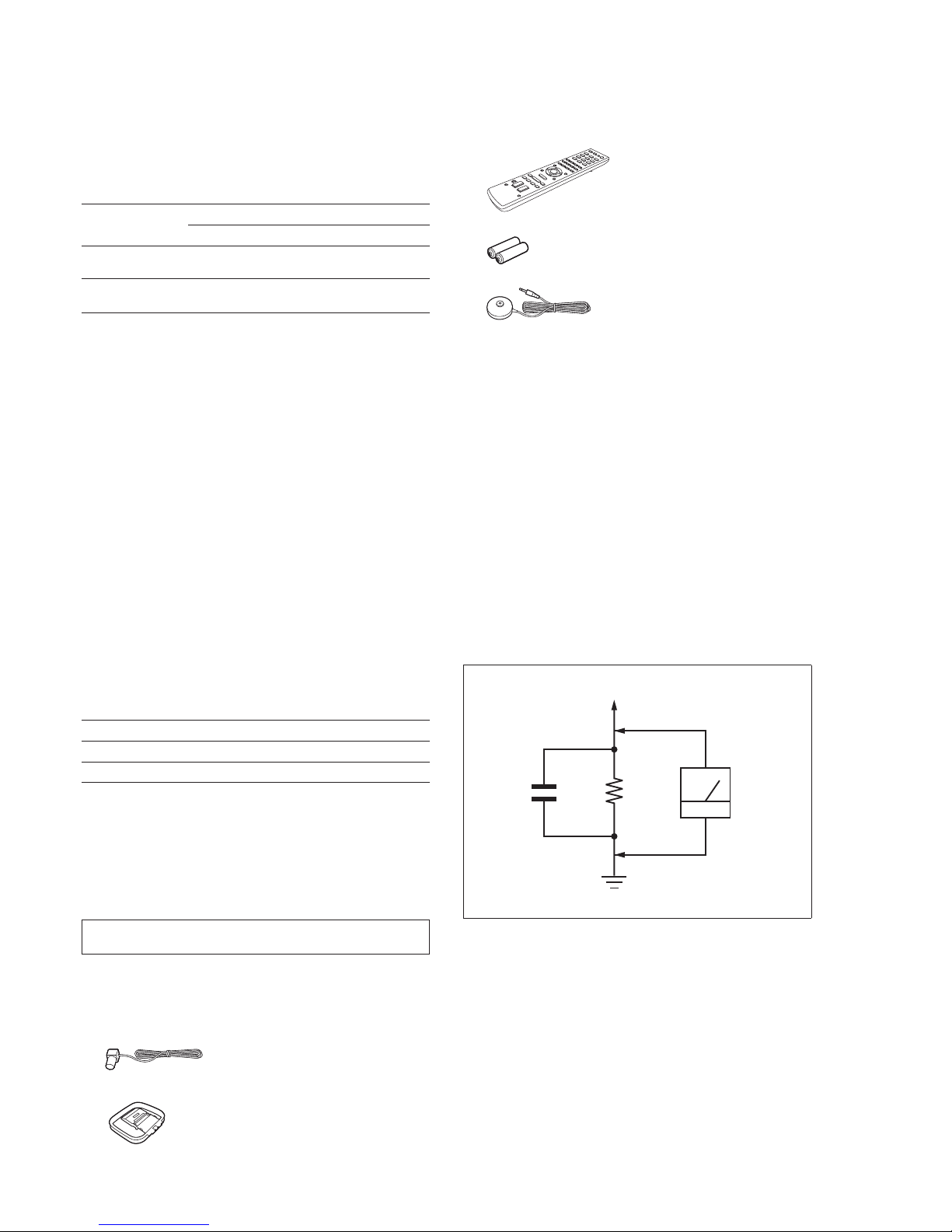
3. Measuring the voltage drop across a resistor by means of a VOM or
battery-operated AC voltmeter. The “limit” indication is 0.75 V, so
analog meters must have an accurate low-voltage scale. The Simpson 250 and Sanwa SH-63Trd are examples of a passive VOM that
is suitable. Nearly all battery operated digital multimeters that have a
2 V AC range are suitable. (See Fig. A)
1.5 kΩ0.15 μF
AC
voltmeter
(0.75 V)
To Exposed Metal
Parts on Set
Earth Ground
Fig. A. Using an AC voltmeter to check AC leakage.
STR-DH720/DH720HP
3
TABLE OF CONTENTS
1. SERVICING NOTES
...................................................... 3
2. DISASSEMBLY
2-1. Case ..................................................................................... 5
2-2. D-VIDEO Board ................................................................. 6
2-3. Front Panel Section ............................................................. 6
2-4. Back Panel Section ............................................................. 7
2-5. DIGITAL Board .................................................................. 7
2-6. MAIN Board Section .......................................................... 8
2-7. MAIN Board ....................................................................... 8
3. TEST MODE ..................................................................... 9
4. ELECTRICAL ADJUSTMENT ....................................11
5. DIAGRAMS
5-1. Block Diagram – TUNER/AUDIO Section – ................... 13
5-2. Block Diagram – DIGITAL Section – .............................. 14
5-3. Block Diagram – STANDBY-A VIDEO PC Section–...... 15
5-4. Block Diagram – D-VIDEO Section – ............................. 16
5-5. Block Diagram – KEY/DISPLAY/USB Section – ........... 17
5-6. Block Diagram – POWER KEY Section – ....................... 18
5-7. Printed Wiring Board – DIGITAL Board (Side A) – ........ 20
5-8. Printed Wiring Board – DIGITAL Board (Side B) – ........ 21
5-9. Schematic Diagram – DIGITAL Board (1/4) –................. 22
5-10. Schematic Diagram – DIGITAL Board (2/4) –................. 23
5-11. Schematic Diagram – DIGITAL Board (3/4) –................. 24
5-12. Schematic Diagram – DIGITAL Board (4/4) –................. 25
5-13. Printed Wiring Board – MAIN Board – ............................ 26
5-14. Schematic Diagram – MAIN Board (1/4) – ...................... 27
5-15. Schematic Diagram – MAIN Board (2/4) – ...................... 28
5-16. Schematic Diagram – MAIN Board (3/4) – ...................... 29
5-17. Schematic Diagram – MAIN Board (4/4) – ...................... 30
5-18. Printed Wiring Board – D-VIDEO Board (Side A) – ....... 31
5-19. Printed Wiring Board – D-VIDEO Board (Side B) – ....... 32
5-20. Schematic Diagram – D-VIDEO Board (1/4) – ................ 33
5-21. Schematic Diagram – D-VIDEO Board (2/4) – ................ 34
5-22. Schematic Diagram – D-VIDEO Board (3/4) – ................ 35
5-23. Schematic Diagram – D-VIDEO Board (4/4) – ................ 36
5-24. Printed Wiring Board –
STANDBY-A VIDEO PC Board – ................................... 37
5-25. Schematic Diagram –
STANDBY-A VIDEO PC Board – ................................... 38
5-26. Printed Wiring Boards – PANEL Section – ...................... 39
5-27. Schematic Diagram – PANEL Section – .......................... 40
5-28. Printed Wiring Board – DCDC Board – ........................... 41
5-29. Schematic Diagram – DCDC Board – .............................. 42
5-30. Printed Wiring Board – USB Board – .............................. 43
5-31. Schematic Diagram– USB Board – .................................. 44
5-32. Printed Wiring Board – HEADPHONE Board – .............. 45
5-33. Schematic Diagram – HEADPHONE Board – ................. 45
5-34. Printed Wiring Board – TEMP-SENSOR Board – ........... 45
5-35. Schematic Diagram – TEMP-SENSOR Board – .............. 45
6. EXPLODED VIEWS
6-1. Case Section ...................................................................... 65
6-2. DCDC Board ..................................................................... 66
6-3. Front Panel Section ........................................................... 67
6-4. Back Panel Section ........................................................... 68
6-5. Chassis Section ................................................................. 69
7. ELECTRICAL PARTS LIST ..................................... 70
SECTION 1
SERVICING NOTES
Part No.
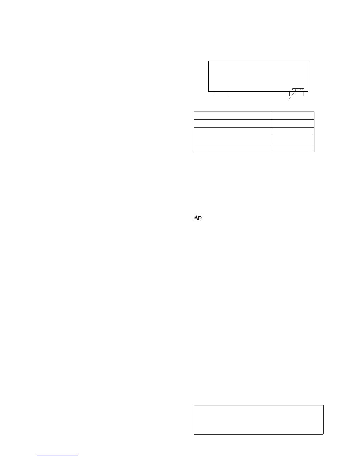
MODEL IDENTIFICATION
–BACK PANEL–
Model Part No.
STR-DH720: US 4-261-825-3
[]
STR-DH720: Canadian 4-261-825-4
[]
STR-DH720: AEP 4-261-825-5
[]
STR-DH720HP: US 4-261-825-7
[]
Notes on chip component replacement
• Never reuse a disconnected chip component.
• Notice that the minus side of a tantalum capacitor may be
damaged by heat.
UNLEADED SOLDER
Boards requiring use of unleaded solder are printed with the
lead-free mark (LF) indicating the solder contains no lead.
(Caution: Some printed circuit boards may not come printed with
the lead free mark due to their particular size)
: LEAD FREE MARK
Unleaded solder has the following characteristics.
• Unleaded solder melts at a temperature about 40 °C higher
than ordinary solder.
Ordinary soldering irons can be used but the iron tip has to be
applied to the solder joint for a slightly longer time.
Soldering irons using a temperature regulator should be set to
about 350 °C.
Caution: The printed pattern (copper foil) may peel away if
the heated tip is applied for too long, so be careful!
• Strong viscosity
Unleaded solder is more viscous (sticky, less prone to fl ow)
than ordinary solder so use caution not to let solder bridges
occur such as on IC pins, etc.
• Usable with ordinary solder
It is best to use only unleaded solder but unleaded solder may
also be added to ordinary solder.
Special Component Notice
The components identified by mark 9 contain confidential
information.
Strictly follow the instructions whenever the components are
repaired and/or replaced.
Notice pour composants spéciaux
Les composants identifiés par la marque 9 contiennent des
informations confi dentielles.
Suivre scrupuleusement les instructions chaque fois qu’un composant est remplacé et / ou réparé.
Note: Refer to supplement-1 for the printed wiring board,
schematic diagram and electrical parts list of D-VIDEO
board (Suffix-21), DIGITAL board (Suffix-21), DCDC
board (Suffi x-21), MAIN board (Suffi x-24) and STANDBY-
AVIDEO MT PC Board (Suffi x-24).
Ver. 1.2
STR-DH720/DH720HP
4
NOTE OF REPLACING THE IC1500 AND IC1600 ON THE
DCDC BOARD
IC1500 and IC1600 on the DCDC board cannot exchange with
single. When these parts on the DCDC board are damaged,
exchange the entire mounted board.
NOTE OF REPLACING THE IC2106 ON THE DIGITAL
BOARD
IC2106 on the DIGITAL board cannot exchange with single.
When this part on the DIGITAL board is damaged, exchange the
entire mounted board.
NOTE OF REPLACING THE IC3500 AND IC3501 ON THE
D-VIDEO BOARD
IC3500 and IC3501 on the D-VIDEO board cannot exchange with
single. When these parts on the D-VIDEO board are damaged,
exchange the entire mounted board.
NOTICE OF BOARD VERSION CHECK
D-VIDEO board (Suffi x-11), DIGITAL board (Suffi x-11), DCDC
board (Suffix-11), MAIN board (Suffix-13) and STANDBY-A
VIDEO PC board (Suffi x-13) is synchronised. When any of the
mounted board replacement is necessary, check the defective
board version and order the same version of mounted board in
part list.
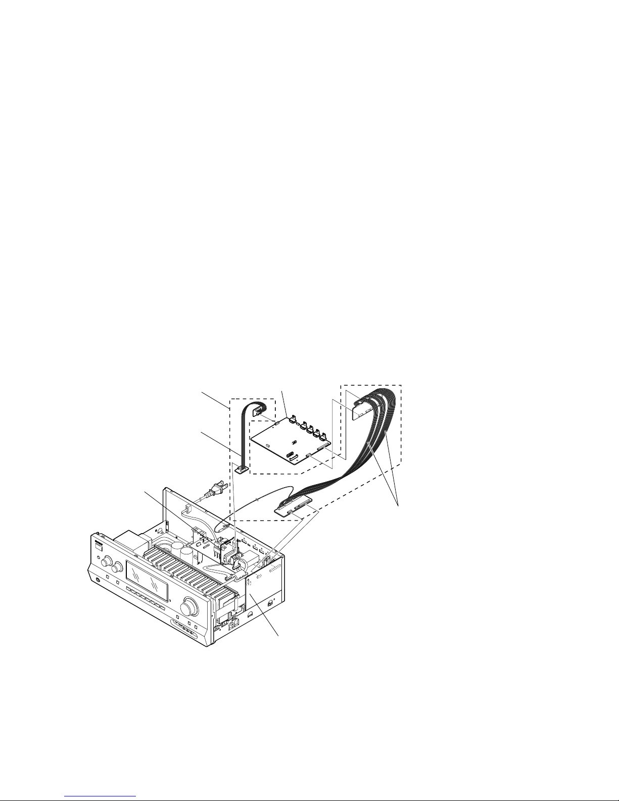
MICOM (IC2105) ON DIGITAL BOARD SERVICE POSITION
• In checking the MICOM (IC2105) on the DIGITAL board,
prepare a set of extension jigs (A-1825-238-A) which consists
of two extension cables.
Connect jig to the DCDC board (CN1501 (6P))
and D-VIDEO board (CN3510 (6P)).
Connect jig to the DIGITAL board (CN2513 (20P)),
(CN2603 (8P)) and D-VIDEO board (CN3003 (20P)),
(CN3004 (8P)).
DCDC board
D-VIDEO board
DIGITAL board
Extension jigs
(A-1825-238-A)
Ver. 1.2
STR-DH720/DH720HP
5
SECTION 2
DISASSEMBLY
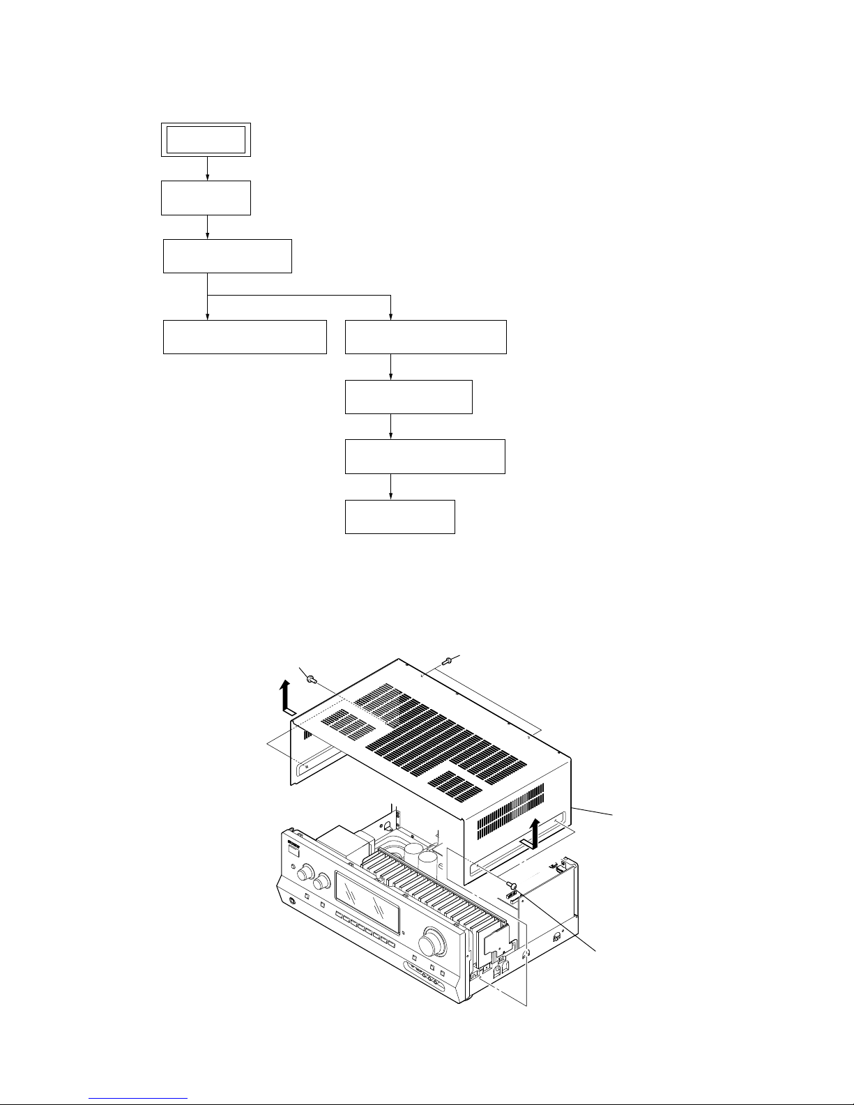
Note:
This set can be disassemble according to the following sequence.
Note:
Follow the disassembly procedure in the numerical order given.
2-1. CASE
2-2. D-VIDEO BOARD
(Page 6)
2-3. FRONT PANEL SECTION
(Page 6)
2-6. MAIN BOARD SECTION
(Page 8)
2-7. MAIN BOARD
(Page 8)
2-4. BACK PANEL SECTION
(Page 7)
2-5. DIGITAL BOARD
(Page 7)
2-1. CASE
(Page 5)
SET
3 two screws
(+BVTP 3 u 8)
4
4
2 two screws
(+BVST 4 u 8)
5 case
1 two screws
(+BVST 4 u 8)
STR-DH720/DH720HP
6
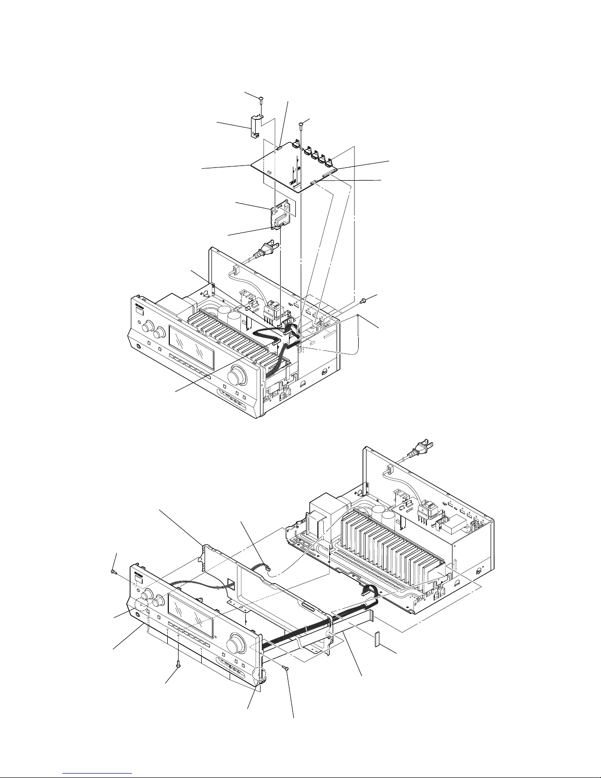
2-2. D-VIDEO BOARD
2-3. FRONT PANEL SECTION
1 wire (flat type) (25 core) (CN2116)
3 CN391 (5P)
2 cushion (R)
7 shield, sub chassis
5 seven screws
(+BVTP 3 u 8)
4 one screw
(+BVTP 3 u 8)
4 one screw
(+BVTP 3 u 8)
6 claw
6 claw
8 front panel section
5 one screw
(+BVTP 3 u 8)
8 CN3510 (6P)
9 CN3003 (20P)
9 CN3004 (8P)
0 D-VIDEO board
qa CN1500 (7P)
qs DCDC board
6 five screws
(+B 3 u 5)
C
B
C
B
1 cut the cable tie
2 CN3007 (13P)
3 CN3200 (8P)
4 one screw
(+BVTP 3 u 8)
7 bracket holder
Ver. 1.2

STR-DH720/DH720HP
7
2-4. BACK PANEL SECTION
2-5. DIGITAL BOARD
1 cut the cable tie
2 CNP902 (2P)
3 CN906 (4P)
5 five screws
(+BVTP 3 u 8)
4 wire (flat type)
(9 core) (CN2003)
(US, CND)
7 eight screws
(+BVTP 3 u 8)
8 CN271 (14P)
6 three screws
(+BVTP 3 u 8)
9 back panel section
1 CN2501 (4P)
2 CN2114 (19P)
2 CN2105 (19P)
3 DIGITAL board
STR-DH720/DH720HP
8
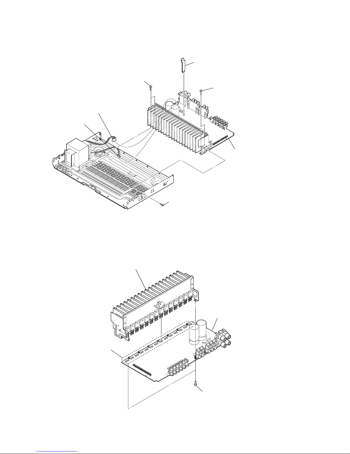
2-6. MAIN BOARD SECTION
3 heatsink block
2 two screws
(+BVTP 3 u 8)
4 MAIN board
1 Remove the
forty-two solders.
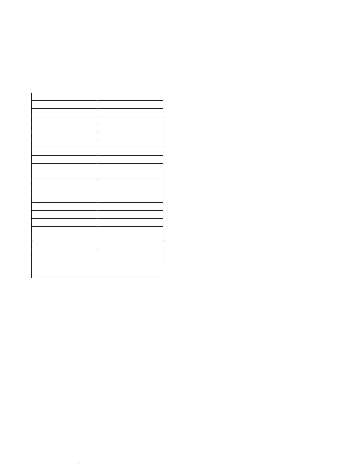
2-7. MAIN BOARD
Note: This illustration sees the MAIN board from back side.
4 one screw
(+BVTP 3 u 8)
6 two screws
(+BVTP 3 u 8)
7 MAIN board section
5 two screws
(+BVTP 3 u 8)
1 CNP920 (5P)
3 LOCK board
2 CNP930 (5P)

STR-DH720/DH720HP
9
SECTION 3
TEST MODE
AM CHANNEL STEP 9 kHz/10 kHz SELECTION MODE
(US and Canadian only)
* Either the 9 kHz step or 10 kHz step can be selected for the
AM channel step.
* Procedure:
1. Press the [
?/1
] button to turn on the main power.
2.
Turn the [INPUT SELECTOR] buttons to select the “AM TUNER”.
3. Press the [?/1] button to turn off the main power.
4. While pressing the [TUNING MODE] button, press the [?/1]
button to turn on the main power.
5. Either the message “9k STEP” or “10k STEP”.
6. After a few second, “AM 531
kHz
” or “AM 530
kHz
” appears,
select the desire step.
VACUUM FLUORESCENT DISPLAY TEST MODE
* All fl uorescent segments are tested.
When this test is activated, all segments light on at the same
time, then each segment lights on one after another.
* Procedure:
While depressing the [TUNING +] and the [DIMMER] but-
tons simultaneously, press the [
?/1
] button to turn on the main
power.
1. ALL segments light on.
LH RH SW
L RC
SBL SBRSB
SL SRS
xzIIPL
D + EX
LFE
COAX
HDMI
OPT
-ES
MSTR
96/24
HI RES
NEO:6
LBR
S-AIR
LPCM
TrueH D
SLEEP
D.RANGE
AAC ST
dB RDS
k Hz m
MHz ft.
DTS
DTS-HD
2. Press the [DISPLAY] control, confi rm display.
LH RH SW
LRC
SBL SBRSB
SL
SRS
zPL
+
LFE
COAX
HDMI
OPT
-ES
MSTR
96/24
HI RES
NEO:6
LBR
S-AIR
LPCM
TrueH D
SLEEP
D.RANGE
AAC
dB
k m
ft.
DTS
DTS-HD
3. Press the [DISPLAY] control, confi rm display.
LH RH SW
L R
SBL SBR
S
xIIPL
D EX
LFE
COAX
HDMI
OPT
-ES
MSTR
96/24
HI RES
NEO:6
LBR
S-AIR
LPCM
TrueH D
SLEEP
D.RANGE
ST
RDS
Hz
MHz
DTS
DTS-HD
4. Press the [DISPLAY] control, all segments light off.
SOUND FIELD CLEAR MODE
* The preset sound fi eld is cleared when this mode is activated.
Use this mode before returning the product to clients upon
completion of repair.
* Procedure:
1. While depressing the [MUSIC] button, press the [
?/1
] button
to turn on the main power.
2.
The message “S.F. CLEAR” appears for a moment and initialization is performed.
SOFTWARE VERSION DISPLAY MODE
The software version is displayed.
* Procedure:
1. While pressing the [TUNING MODE] and [DISPLAY] but-
tons, press the [
?/1
] button to turn on the main power.
2. The message “H7 ** MX.XX” appears.
**: Destination
X.XX: Software version
Each time the [DISPLAY] button is pressed, “H.VER X.XX”,
“S.VER X.XX” and “F.VER X.XX” appear in this order, and
returns to the “H7 ** MX.XX” display.
KEY CHECK MODE
* Button check
* Procedure:
1. While depressing the [TUNING +] and the [MUTING] buttons simultaneously, press the [
?/1
] button to turn on the
main power.
2. Either the message “REST 14” appears.
Every pressing of any button other than the [
?/1
] counts
down the buttons. The buttons which are already counted
once are not counted again. When all buttons are pressed
“REST 00” appears.
SWAP ALL MODE
* The signal will be swap to all channel so that all speaker will
have sound output.
* Procedure:
1. While depressing the [TUNING MODE] and the [MOVIE]
buttons simultaneously, press the [
?/1
] button to turn on the
main power.
2. “SWAP. MODE” appears.
INITIALIZE MODE
All preset contents are cleared when this mode is activated. Use
this mode before returning the product to clients upon completion
of repair.
(a) SHIPMENT MODE
* Procedure:
1. While pressing the [TUNING MODE] and [DIMMER] buttons, press the [
?/1
] button to turn on the main power.
2. The message “CLEARING” appears and the memories are
reset to the default values.
3. When done, the message “CLEARED” appears, the set will
power off.
(b) ALL CLEAR INITIALIZE
* Procedure:
1. While pressing the [TUNING MODE] and [MUTING] buttons, press the [?/1] button to turn on the main power.
2. The message “CLEARING” appears and the memories are
reset to the default values.
3. When done, the message “CLEARED” appears, the set will
power on.
(c) USER INITIALIZE
* Procedure:
1. Hold the [
?/1
] button for 5 seconds.
2. The message “CLEARING” appears on the display.
3. After few seconds, “CLEARED” appears.
PROTECTOR AUTO OFF
* To disable auto off after protector occur.
* Procedure:
1. While depressing the [INPUT MODE] and the [A.F.D.] buttons simultaneously, press the [
?/1
] button to turn on the main
power.
2. “PROT OFF” appears and switch on the set.
STR-DH720/DH720HP
10
HISTORY MODE
The state that the set is used is memorized.
* Procedure:
1. While pressing the [INPUT MODE] and [MUSIC] buttons,
press the [
?/1
] button to turn on the power and “HISTORY”
is displayed.
2. Each time the [ r ] [ R ] key of remote commander is pressed,
the item is switched in order as follows.
Items Display
Protector count COUNT XX
Total single power on time XXXXXHXX 01
Sound fi eld SND FLD
Input function FUNCTION
Input mode INP MODE
Digital select DIG IN
Stream information STREAM
Signal confi guration CO XXXXX
Headphones HP XXX
Volume VOL XX
Bass BASS XXX
Treble TREB XXX
Level FL/FR F XXXXXX
Level SL/SR S XXXXXX
Level CT/SW CWXXXXXX
Level BL/BR B XXXXXX
Level LH/RH H XXXXXX
Total power on time XXXXXHXX 02
Muting MUTE XXX
Power on counter
(Rebox test mode)
REBX.XXXX
Protector Type PROTXXXX
Temperature record TEM XXXX
DCAC TEST MODE
* Procedure:
1. While pressing [INPUT MODE] and [MOVIE] buttons, press
the [?/1] button to turn on the main power.
2. The message “SOURCE” or “MIC” appears.
Repeat step 1 to toggle between “SOURCE” and “MIC”.
SOURCE: normal mode
MIC: mode that output audio from mic input
USB UPDATE TEST MODE
To update Main MCU, Video MCU, DSP serial fl ash and Hudson
II software through USB.
* Procedure:
1. Plug in USB device in power off condition.
2. While pressing the [TONE MODE] and the [DISPLAY]
buttons, press the [
?/1
] button to turn on the main power.
3. The message “UPDATING” appears.
4. If the updating progress succeeds, the message “COMPLETE”
appears.
5. If the updating progress fails, the message “ERROR” appears.
USB UPDATE VERSION MODE
Function that displays the version number to check whether USB
update is necessary or not.
* Procedure:
1. While pressing [TONE MODE] and [DIMMER] buttons,
press the [
?/1
] button to turn on the main power.
2. The message “VER X.XXX” is displayed. “X.XXX” is
calculated by adding all fi rmware version.
Example:
(MAIN ver. + DSP ver. + HDMI ver. + FARO ver. + 6)/10 =
Displayed version
MAIN = 1.02, DSP = 1.01, HDMI = 1.00, FARO = 1.03
↓
(1.02 + 1.01 + 1.00 + 1.03 + 6)/10 = 1.006
1.006 = X.XXX

STR-DH720/DH720HP
11
SECTION 4
ELECTRICAL ADJUSTMENT
VIDEO CALIBRATION ADJUSTMENT
Adjustment to decide the standard of the video input signal.
Note: After replacing DIGITAL VIDEO board, or after “RESET” of the
special menu mode is executed, perform this adjustment.
1. Adjustment jig
The color pattern generator that can output 100% in NTSC/PAL/
HD color bar signal to the component and the composite at the
same time is necessary for the adjustment.
When there is no color pattern generator, it is possible to substitute
it by the Blu-ray Disc player that can output the component
terminal and the video terminal at the same time (Substitution
model name example: BDP-S350).
However, please do the following signal output confi rmation with
the oscilloscope beforehand when substituting it with the Blu-ray
Disc player.
2. Video calibration adjustment
2-1. Connection
color pattern
generator
or
Blu-ray
Disc player
set
HDMI TV
OUT
ANALOG VIDEO board
COMPONENT VIDEO
SAT/CATV (IN2)
SAT/CATV VIDEO IN jack
2-2. Procedure for color pattern generator
1. It connects of step 2-1, and then turn on the main power.
2. “SAT/CATV” is selected by using [INPUT SELECTOR] dial.
3. Input NTSC color bars signal from the color pattern generator.
4. Press the [
?/1
] button to turn off the main power.
5.
While pressing the [MOVIE] and [SPEAKERS] buttons, press
the [
?/1
] button to turn on the main power. When correctly
entering the test mode “FIN_ _ _” is displayed (press the
buttons again until the message appear).
6. The NTSC signal adjustment is begun when press the cross
(center of cursor) button of remote commander, and the display
changes from “N-MWX_ _ _” to “N-MWOCDV” little by little.
Finally, the display returns to the display of “FINN _ _”.
7. Input PAL color bars signal from the color pattern generator.
8. Perform step 6 to 7 for the PAL signal adjustment.
9. Input HD color bars signal (720p or 1080i) from the color
pattern generator.
10. Perform step 6 to 7 for the HD signal adjustment.
11. Then turn off the main power.
2-3. Procedure for Blu-ray Disc player
1. It connects of step 2-1, and then turn on the main power of set
and Blu-ray Disc player.
2. “SAT/CATV” is selected by using [INPUT SELECTOR] dial.
3. Press the OPEN/CLOSE button of the Blu-ray Disc player, and
DVD test disc “HLX-504 (Part No. J-6090-088-A)” or “HLX513 (Part No. J-2501-305-A)” is insert. The disc playback
automatically becomes start “Main Menu” is display.
4. “1.Color Bar 100%” of “1.Video Signal” is reproduced, and
100% in the color bar is displayed in the TV monitor, playing
the Blu-ray Disc player is pause playback.
5. Press the [
?/1
] button to turn off the main power of the set.
6.
While pressing the [MOVIE] and [SPEAKERS] buttons, press
the [
?/1
] button to turn on the main power of the set. When
correctly entering the test mode “FIN_ _ _” is displayed
(press the buttons again until the message appear).
7. The NTSC signal adjustment is begun when press the cross
(center of cursor) button of remote commander, and the display
changes from “N-MWX_ _ _” to “N-MWOCDV” little by little.
Finally, the display returns to the display of “FINN _ _”.
8. Press the OPEN/CLOSE button of the Blu-ray Disc player, and
change to DVD test disc “HLX-506 (Part No. J-6090-077-A)”
or “HLX-507 (Part No. J-6090-078-A)”. The disc playback
automatically becomes start “Main Menu” is display.
9. “1.Color Bar 100%” of “1.Video Signal” is reproduced, and
100% in the color bar is displayed in the TV monitor, playing
the Blu-ray Disc player is pause playback.
10. The PAL signal adjustment is begun when press the cross
(center of cursor) button of remote commander. Finally, the
display returns to the display of “FINN P _”.
11. Press the OPEN/CLOSE button of the Blu-ray Disc player, and
change to DVD test disc “HLX-104 (Part No. J-6090-199-A)”.
The disc playback automatically becomes start “Main Menu”
is display.
12. “59.94Hz, 1080i” → “1.Video Signal” → “1.Color Bar 100%”
is selected, and 100% in the color bar is displayed in the TV
monitor, playing the Blu-ray Disc player is pause playback.
13. The video output of the Blu-ray Disc player is switched 1080i
(The output from the component terminal of the Blu-ray Disc
player becomes 1080i output).
14. The HD signal adjustment is begun when press the cross
(center of cursor) button of remote commander. Finally, the
display returns to the display of “FINN P N”.
15. Then turn off the main power.

STR-DH720/DH720HP
12
FM AUTO STOP CHECK
generator
OUT (75 Ω)
set
Procedure:
1. Turn on the set.
2. Input the following signal from Signal Generator to FM antenna input directly.
* Carrier Frequency: A = 87.5 MHz, B = 98 MHz, C = 108 MHz
Deviation : 75 kHz
Modulation : 1 kHz
ANT input : 35 dBu (EMF)
Note:
Please use 75 ohm “coaxial cable” to connect SG and the set. You
cannot use video cable for checking.
Please use SG whose output impedance is 75 ohm.
3. Set to FM tuner function and scan the input FM signal with
automatic scanning.
4. Confi rm that input Frequency of A, B and C are detected and
automatic scanning stops.
The stop of automatic scanning means “The station signal is
received in good condition.”
STR-DH720/DH720HP
STR-DH720/DH720HP
1313
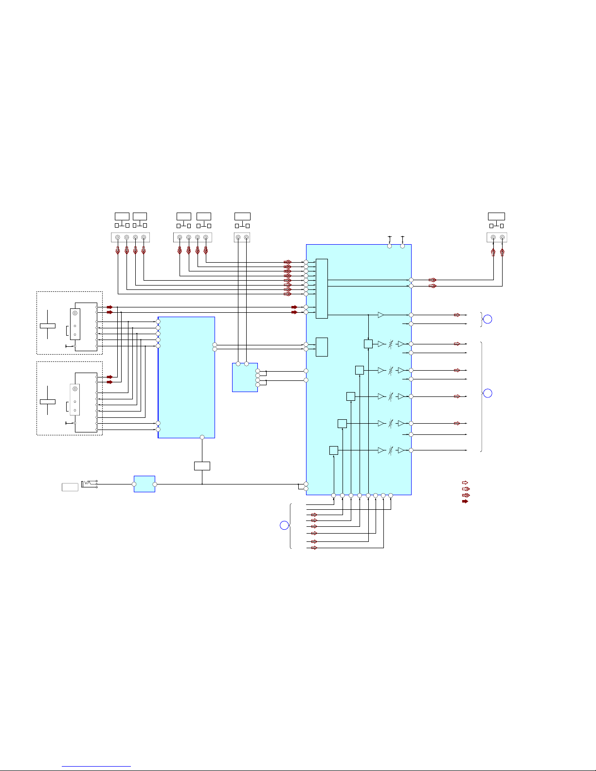
5-1. BLOCK DIAGRAM – TUNER/AUDIO Section –
SECTION 5
DIAGRAMS
C-CH
SR-CH
FR-CH
SL-CH
FL-CH
R-IN
L-IN
SW
SEL
C
SEL
SB
SEL
SL
SEL
R-CH
INR2
INL2
INL3
INR3
R-CH
R-CH
DIR
FUNCTION SELECT
IC400
VCCVEE
+7V
SEL
SW
MCU
I/F
-7V
SW OUT
SBL
SBR
C OUT
SL OUT
FL OUT
8
21
23
SYSTEM
CONTROL
IC2105 (1/5)
AUDIO AMP
IC101
TUNER_LAT
9
TUNER_MOSI
10
TUNER_CLK
EVOL_DATA
DCAC_MUTE
EVOL_CLK
TUNER_SD
TUNER_MISO
97
96
41
57
58
12 8
10
62
11
59
60
75
14
13
18
17
SBR-CH
R-CH
19
SW-CH
16
7166 70 68 69
SR OUT
FR OUT
72 73 67
48
47
52
51
42
41
46
45
SBL-CH
20
15
76
25
26
L
SEL
5
1
OP AMP
IC4121
5 3
1
2
617
6
1OUT
2+
AM
TN1
FM/AM TUNER UNIT
L-CH
US, CND
SD
CE
DO
DI
CLK
TU+9V
FM 75ȍ
COAXIAL
ANTENNA
R-CH
J401 (1/2)
J409
-1 -2 -4 -5
-4 -5 -7 -8
J4100
AUTO CAL
MIC
J401 (2/2)
-1 -2
SA-CD/CD
AUDIO IN
L R
TV
AUDIO IN
L R
J101 (1/2)
VIDEO 2 IN
AUDIO
L R
L R
VIDEO 1
AUDIO IN
L R
SAT/CATV
AUDIO IN
L R
VIDEO 1
AUDIO OUT
11
TUNER_RDS_CLK
22
TUNER_RDSDATA
ECE
AM
TN1
FM/AM TUNER UNIT
L-CH
SD
CE
DO
DI
CLK
TU+9V
FM 75ȍ
COAXIAL
ANTENNA
R-CH
RDS INT
RDS DATA
6LJQDOSDWK
: TUNER (FM/AM)
: VIDEO (AUDIO)
: CD (ANALOG)
: TUNER
5FKLVRPLWWHGGXHWR
VDPHDV/FK
$EEUHYLDWLRQ
&1' &DQDGLDQPRGHO
(&( &RQWLQHQWDO(XURSHDQ
(DVW(XURSHDQ
DQG5XVVLDQPRGHOV
DIGITAL
SECTION
(Page 14)
DIGITAL
SECTION
(Page 14)
POWER KEY
SECTION
(Page 18)
MIC MUTE
DRIVER
Q4121 - Q4123
A
B
C
STR-DH720/DH720HP
STR-DH720/DH720HP
1414
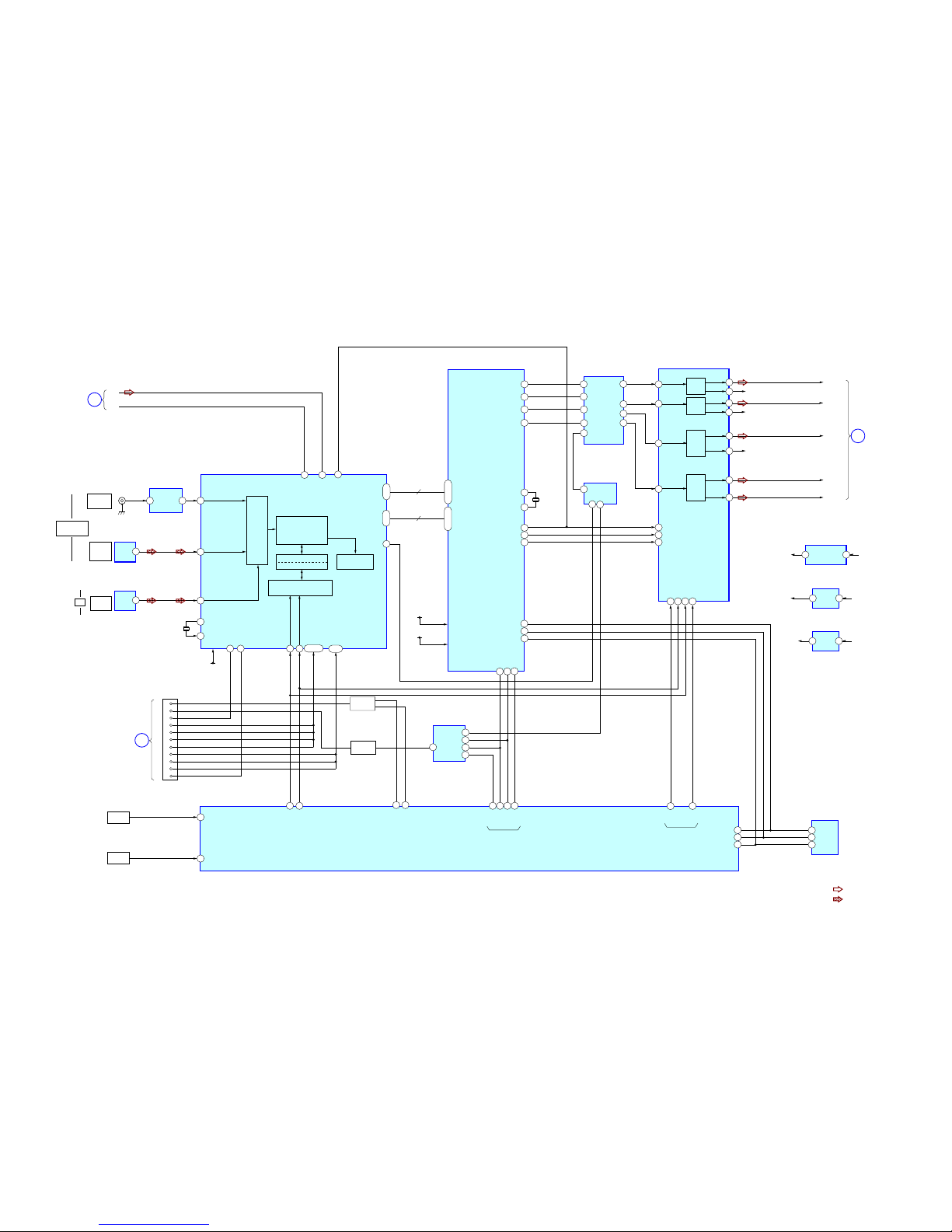
5-2. BLOCK DIAGRAM – DIGITAL Section –
55
56
57
DSP_MISO
DSP_MOSI
DSP_SPICLK
TUNER/
AUDIO
SECTION
(Page 13)
C
D-VIDEO
SECTION
(Page 16)
D
TUNER/
AUDIO
SECTION
(Page 13)
A
L-IN
R-IN
3 - 5
17 - 19
12 - 14
75, 97,103
6, 8 -10
74, 95,101
6LJQDOSDWK
: TUNER (FM/AM)
: DVD (DIGITAL)
5FKLVRPLWWHGGXHWR
VDPHDV/FK
R-CH
COAXIAL
BD/DVD IN
DIGITAL
(ASSIGNABLE)
OPTICAL
IN
TV
J2301
OPTICAL
SAT/CATV
IN
X2800
25MHz
CN2513
9
10
7
8
11
12
13
14
16
18
CEC DATA
SWITCH
1
482047
73
94
86
X2801
0+]
CLKIN
SBL/SBR_OUT
SL/SR_OUT
C/SW1_OUT
L/R_OUT
24
XTAL2
25
92
BCLK_OUT
MCLK_IN
98
LRCLK_OUT
SPICLK
Y0
B0
Y3
Y1
SEL
MOSI
MISO
IRQ/GPIO
FLAG1
FLAG2
99
70 71 68
40
39
88 89
2529 24
INPUT
DATA
DEMODULATOR
3D3E'(7(&7,21 LOCK
DETECTION
MICROPROCESSOR
I/F
&ELW'(7(&7,21
18
1
OUT
DIGITAL OPTICAL
RECEIVE
IC2352
DIGITAL AUDIO
INTERFACE RECEIVER
IC2006 (1/2)
23
WAVE SHAPER
IC2303
IC2010
24
9
REG
9
VDDI
9
VDDE
9
TEMP_SENSOR_1
VDD
9
9
+5V REG
IC2421
+5V
+7VVOUT VIN
DSP
IC2801
COM_CLK
COM_DATA
MC/SCL
MDI/SDA
33
31
TH251
TH252
26
TEMP_SENSOR_2
27
XTO
RXIN2/
'9'B&RD[LDO,Q
RXIN4/TV OPT IN
LRCK
1
OUT
IN2 OUT3
DIGITAL OPTICAL
RECEIVE
IC2351
32
RXIN3/
SAT/CATV OPT IN
XTI
SYSTEM
CONTROL
IC2105 (2/5)
1114
94
95
MUTE
LATCH
MUTE
ML/I2S
12
MC/IWL13MD/DM
DIN3
DIN4/DNC
FL OUT
R-CH
VO3L
VO3R
VO1L
VO1R
VO2L
VO2R
9
26
25
7
2
MCK
3
BCK
LRCK
4
D/A CONVERTER
IC2501
DAC
DIN2
SL OUT
R-CH
22
21
DAC
DIN1
C OUT
23
SW OUT
24
DAC
DAC
DSP
69
RXIN6/HDMI_ARC
RXIN7/HDMI_SPDIF
VINR
VINL
SCKO
IC2005
13
+9V
REG
+9V
+15V
Q2702 - Q2705
134
135
136
13
3
11
10
8
6
4
1
2
10
DAC
VO4L
VO4R
20
19
SBL OUT
8
2
5
1
SCHMITT TRIGGER
IC2009
EEPROM
IC2802
12
4
7
1
3
MUTING
IC2804
3
3
28
47 43
HDMI_CECIN
HDMI_CECOUT
SEL
NPCM
ERROR
INT
88
38
39
40
SCK
SI
SO
A3 Y0
Y3
Y1
Y2
A2
A1
A0
B0
CK
D
Q
SIGNAL SELECTOR
IC2805
MUTE
SWITCH
Q2706
Ver. 1 .1
STR-DH720/DH720HP
STR-DH720/DH720HP
1515
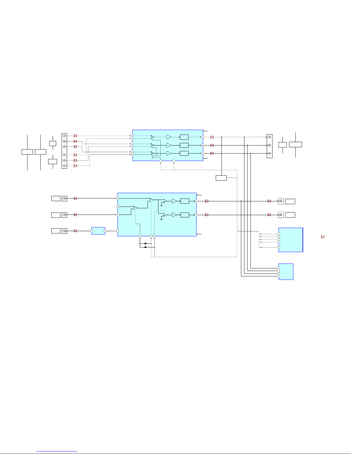
5-3. BLOCK DIAGRAM – STANDBY-A VIDEO PC Section –
14
13
5
7
9
1
75ȍ
DRIVER
6dB AMP
15
75ȍ
DRIVER
6dB AMP
V_COMP_SW2
V_SEL_SW2
V_MUTE
V_SEL_SW1
COMP_SW2
VSEL_2
COMP_DET
V_MUTE_1
VSEL_1
SYSTEM CONTROL
IC2105 (3/5)
-5V
-5V-3
+5V
+5V-3
VOUT1
VOUT2
VIN1
VIN4
VIN3
VIN2
VSEL_2
SW1
2
SW510SW2
INPUT SELECT
IC210
VIDEO AMP
IC203
CH1 IN2
CH2 IN2
CH3 IN2
CH1 IN3
CH2 IN3
CH3 IN3
4
SW2
COMP_SW2
6dB AMP
6dB AMP
6dB AMP
23
PS
V_MUTE_1
COMPONENT VIDEO SELECT
IC220
82
83
84
85
COMP_DET
81
A1P
A4P
C1P
B1P
VIDEO CONTROLLER
IC3201 (1/2)
219
223
221
249
VSEL_1
D204
VIDEO
DETECT
COMP_DET
Q202
Q201
3
5
10
15
13
12
CH1 OUT
CH2 OUT
CH3 OUT
24
22
20
V-1,-2
-5V-3
V+1,+2
+5V-3
75ȍ
DRIVER
75ȍ
DRIVER
75ȍ
DRIVER
4 1V-IN V-OUT
VIDEO 2 IN
VIDEO
Y
P
B
PR
Y
P
B
PR
J220 (1/2)
BD/DVD
(IN 1)
SAT/CATV
(IN 2)
ASSIGNABLE
(INPUT ONLY)
COMPONENT
VIDEO
5
6
7
-1
-2
-3
J211 (1/2)
J210 (1/2)
Y
P
R
PB
J220 (2/2)
MONITOR
OUT
COMPONENT
VIDEO
9
10
11
J210 (2/2)
J211 (2/2)
VIDEO 1
VIDEO IN
SAT/CATV
VIDEO IN
J101 (2/2)
MONITOR
VIDEO OUT
VIDEO 1
VIDEO OUT
-3
-1
-3
-1
6LJQDOSDWK
: VIDEO
STR-DH720/DH720HP
STR-DH720/DH720HP
1616
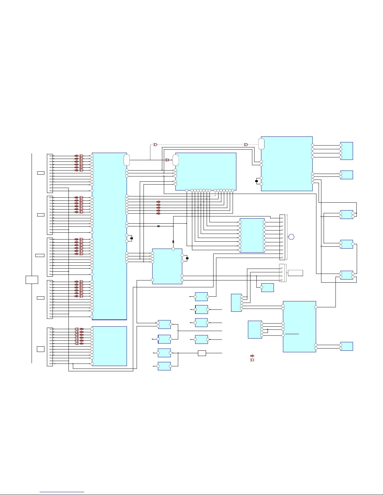
5-4. BLOCK DIAGRAM – D-VIDEO Section –
125
R1X2+
DATA2+
DATA2–
DATA1+
DATA1–
DATA0+
DATA0–
CLOCK+
CLOCK–
SCL (5V)
SDA (5V)
HOT PLUG DET
CEC
+5V POWER
DATA2+
DATA2–
DATA1+
DATA1–
DATA0+
DATA0–
CLOCK+
CLOCK–
SCL (5V)
SDA (5V)
HOT PLUG DET
CEC
+5V POWER
DATA2+
DATA2–
DATA1+
DATA1–
DATA0+
DATA0–
CLOCK+
CLOCK–
SCL (5V)
SDA (5V)
HOT PLUG DET
CEC
+5V POWER
R1X2R1X1+
R1X1-
Q0
I
Q35
D0
I
D35
R1X0+
R1X0R1XC+
R1XCDSCL1
124
123
122
121
120
119
118
35
134
R2X2+
R2X2R2X1+
R2X1R2X0+
R2X0R2XC+
R2XC-
RESET#
INT
133
132
131
130
129
128
127
DSCL2
DSDA2
39
40
HPD2
R3X2+
R3X2R3X1+
R3X1R3X0+
R3X0R3XC+
R3XCDSCL3
DSDA3
HPD3
38
TX2+
TX2TX1+
TX1TX0+
TX0TXC+
TXCDSCL
DSDA
HPD
40
39
37
36
34
33
31
30
46
47
51
DSDA1
HPD1
36
34
DE
73
VSYNC 74
73
HSYNC
75
SCK/DCLK
100
WS/DR0
99
SD0/DL0
101
SD1/DR1
102
SD2/DL1
103
SD3/DR2 104
MCLK
105
SPDIF/DL2
106
GPIO3/MUTEOUT
107
1
DE
VSYNC
HSYNC
DL2
48 CSCL
CSDA49
21
MCLK5DR220DL119DR118DL017DCLK15DR0
16
67
69
12
68
70
28
29
13
R1PWR5V33
R2PWER5V37
R3PWR5V41
IC3500
HDMI RECEIVER
IC3501
HDMI TRANSMITTER (1/2)
RX_RST
RX_INT
CSCL
CSDA
RESET
MD0
TX_5VPWR
39
40
18
16
21
22
23
24
HDMI CONTROLLER
IC3000 (1/3)
IC3501
HDMI TRANSMITTER
(2/2)
IC3201
VIDEO CONTROLLER
(2/2)
4
5
CSDA
CSCL
1
38
DATA2+
DATA2–
DATA1+
DATA1–
DATA0+
DATA0–
CLOCK+
CLOCK–
SCL (5V)
SDA (5V)
HOT PLUG DET
CEC
+5V POWER
4 2
+3.3V
REG
IC3517
HDMI+3.3V
3.3V
HDMI+5V
+4V
6 1
+1.2V
REG
IC3519
HDMI+1.2V
+4V
1 8
IC3515
HDMI+1.8V
+3.3V
5 4
+1.8V
REG
IC3203
+1.8V
+4V
1 8
+1.8V
REG
IC3210
+1.8V
+6V
IC3516
4 5
+5V
REG
IC3521
143
142
141
140
139
138
137
136
43
44
42
CN3000
232C_IN(VU RX)
232C_OUT(VU TX)
RESET
CNVSS
FLASH
PROGRAMMING
5
3
2
1
96-88,
85-77,
70-62,
59-51
98-90,
86-77,
75-67,
63-56
75-82,
83-92,
93-96,
99-102
(Q28-Q35)
(Q16-Q23)
(Q4-Q7)
(Q8-Q11)
DEN/VOP_FLD
DVS/VOP_VS
XTAL
TCLK
X3201
19.6608MHz
4
5
XTALOUT
XTALIN
X3501
27MHz
23
24
X3000
4MHz
XOUT
MUTE
XIN
5
8
IC3502
SELECTOR
9
HSYNC SELECT
IC3206
D3003
9
D3004
+5V
REG
DATA2+
DATA2–
DATA1+
DATA1–
DATA0+
DATA0–
CLOCK–
SCL (5V)
SDA (5V)
HOT PLUG DET
CEC
+5V POWER
CLOCK+
116
115
114
113
112
111
110
109
31
32
30
29
R0X2+
R0X2R0X1+
R0X1R0X0+
R0X0R0XC+
R0XCDSCL0
DSDA0
HPD0
R0PWR5V
20
21
CN2513
DIGITAL
SECTION
(Page 14)
8
9
7
10
11
12
13
14
16
1
18
A6
2Q
2
1D
11
3
1CK
7
A7
8
A2
3
A3
4
A4
5
A5
6
A8
9
A1
Y1
Y8
2
IC3004
BUFFER
18
17
16
15
14
13
12
11
3
1
2
6
EEPROM
IC3208
SCL
5
SDA
4
HSYNC SELECT
IC3205
COM
6
A
1
3
Ch0
Ch1
12
USB MEMORY
IC3005
I2C_SCL
13
87
85
I2C_SDA
1
RESET SIGNAL
GENERATOR
IC3003
OUT
4
HSYNC SELECT
IC3204
OUTY
2
1
INB
INA
106
ROM_SCSn/ROM_CSn
109
ROM_SDI/ROM_WEn
108
ROM_SDO/A16/OPM2
107
ROM_SCLK/A17
DHS/VOP_HS
DCLK/VOP_CLK
MSTR_SCLK
MSTR_SDATA
34
64
35
1
4
11
13
14
13
12
11
15
11
13
4
2
9
3A
232OUT_TX
HSYNC_SEL
USB_IP_SCL
USB_IP_SDA
232IN_RX
SEL_USB_UPDATE
USB_UPDATE_RX
USB_UPDATE_TX
SEL_USB_UP_ST
4B
1Y
1A
3Y
SEL
1Y
3A
4B
/ST
RS-232
SELECTOR
IC3001
USB SELECTOR
IC3002
HDMI CONTROLLER
IC3000 (2/3)
1.8V REG
D3201-
D3202
DCCPWR5V
45
EEPROM
IC3207
6SCK
5SI
2SO
1
CE#
CN3503
4
6
1
3
7
9
10
12
15
16
19
13
18
CN3502
4
6
1
3
7
9
10
12
15
16
19
13
18
CN3500
4
6
1
3
7
9
10
12
15
16
19
13
18
TV OUT
ARC
CN3501
4
6
1
3
7
9
10
12
15
16
19
13
18
HDMI
ASSIGNABLE
(INPUT ONLY)
VIDEO 1
SAT/CATV
GAME
CN3504
4
6
1
3
7
9
10
12
15
16
19
13
18
WS10SCK11SD09SD18SD27SD36SPDIF
4
6LJQDOSDWK
: DVD (DIGITAL)
: VIDEO
BD/DVD
D
Ver. 1 .1

STR-DH720/DH720HP
STR-DH720/DH720HP
1717
5-5. BLOCK DIAGRAM – KEY/DISPLAY/USB Section –
92
FL DISPLAY DRIVER
IC152
14
I
29
31
93
6
7
5
6
40
46
45
51
53
54
X1(X_OUT)
X0(X_IN)
E2P_DATA
E2P_CLK
POWER_KEY
MD2
MD0
RST
SDA
SCL
EEPROM
IC2106
SIRCS
30
FL_DATA
7
DIN
29
FL_LAT
9
STB
31
FL_CLK
8
CLK
GRID1
I
GRID11
SEG1
I
SEG17
VOL_JOG
INPUT_JOG
AD_KEY_2
AD_KEY_1
39
2
REMOTE
CONTROL
SIGNAL
RECEIVER
IC151
OUT
SIRCS
+3.9V DCDC
SYSTEM
CONTROL
IC2105 (4/5)
MD2
MD0
RESET
61
60
FLASH_CLK
SO
59
SI
CLK
SO
SI
12
36
37
RESET SIGNAL GENERATOR
IC2020
42
I
32
TONE_JOG
38
30
VEE
OUTVDD
15
VOUT
7
+IN2OUT2
Q2006
97
HDMI
CONTROLLER
IC3000 (3/3)
REGISTOR CONTROL
IC4102
COMPARATOR
IC4101
DATA PROCESSOR
IC4100
MU_MD0
NC
89
USB_OVC
32
IN2OUT3
LRCK
USB SELECTOR
IC4160
30
RXIN5/USB_SPDIF
DIGITAL AUDIO
INTERFACE RECEIVER
IC2006 (2/2)
84
34
USB-DP
33
40
53
41
USB-DM
XIN-PLL
IRPTO,
KEY-ROW1/MCHNG,
KEY-ROW3/SCL,
KEY-ROW4/SDA
USB_SDA,
USB_SCL,
USB_IPOD_REQ,
USB_MCHNG
XOUT-PLL
8,10,12,13
81,83,88,76
4
IC4161
3.3V
REG
+3.3V
+6V
J4000
iPhone/iPod
5
X2101
4MHz
X4102
16.9344MHz
CN2602
8
9
3
4
5
6
S183
_/1
SW NETWORK
S100-107
SW NETWORK
S108-111,S180-181
T141
CONVERTER
TRANSFORMER
Q141
SWITCHING
TRANSISTOR
EN151
MASTER
VOLUME
2
3
EN181
INPUT
SELECTOR
2
3
EN180
TONE
2
3
ND151
VACUUM
FLUORESCENT
DISPLAY
D141
D142
SWITCHING
DIODE
+3.3V (STBY)
FLASH
PROGRAMMING
3
2
DATA
SWITCH
D4101D4105

STR-DH720/DH720HP
STR-DH720/DH720HP
1818
5-6. BLOCK DIAGRAM – POWER KEY Section –
6
2
3
DRIVE
PRE DRIVER
IC701
IN 1
+VOUT1
-VOUT2
8
12
11
IN 2
+VOUT2
-VOUT2
FL-CH
FR-CH
FL-CH
FR-CH
SL-CH
SBL-CH
SBR-CH
SR-CH
SL-CH
SR-CH
+3.3V
(STBY)
+5V
-5V
+4V
+6V
-7V
+7V
87
6
2
3
DRIVE
PRE DRIVER
IC601
IN 1
+VOUT1
-VOUT2
8
12
11
IN 2
+VOUT2
-VOUT2
99
80
+5V
(STBY)
-5V
REG
IC202
+3.3V
REG
IC2107
1.1V
(STBY)
23
POWER OPERATION AMP
IC2803
-15V
+15V
+7V
REG
IC350
-7V
REG
IC352
+5V
REG
IC201
+4V
REG
21
IC1500
+6V
REG
21
IC1600
FRONT_SPK_A_RY
HP_RY
SBL-SBR_RY
C/SL-SR_RY
PREOUT_SW_RY
HP_DET
FRONT_SPK_A_RY
PROTECTOR
2
BRIDGEABLE_RY
HP_DET
FUSE_DET(RESERVE)
STOP
79
4
HP_RY
3
100
PREOUT_SW_RY
98
C/SL-SR_RY
FRONT_SPK_A_RY
HP_DET
SBL-SBR_RY
HP_RY
PREOUT_SW_RY
C/SL-SR_RY
SYSTEM
CONTROL
IC2105 (5/5)
PRE
DRIVE
C-CH
6
2
3
DRIVE
PRE DRIVER
IC501
IN 1
+VOUT1
-VOUT2
PRE
DRIVE
SW-CH
PRE
DRIVE
6
2
3
DRIVE
PRE DRIVER
IC801
IN 1
+VOUT1
-VOUT2
8
12
11
IN 2
+VOUT2
-VOUT2
PRE
DRIVE
1
SBL-SBR_RY
4
SIGNAL
SELECTOR
IC2032
PHONES
J790
R
L
L
SUBWOOFER
AUDIO OUT
CENTER
SURROUND
R
TB503
TB504
TB503
J405
FRONT
SPEAKERS
IMPEDANCE
USE 8-16ȍ
F901
POWER TRANSFORMER
(SUB)
T902
AC IN ~
RECT
D921
F912
F913
RY901
D990
F910
F911
F940
F941
RECT
D910-913
RECT
D941
D2303
D2302
D2110
PROTECTOR
D326-327, Q320-321,
Q323-325
POWER AMP
Q701-704,
Q751-754
POWER AMP
Q551-554
POWER AMP
Q601-604,
Q651-654
POWER AMP
Q801-802,
Q503-504,
Q851-854
RY350
RY365
RY301
RY375
RELAY
DRIVER
Q375
RELAY
DRIVER
Q365
RELAY
DRIVER
Q301
RELAY
DRIVER
Q350
RY920
RELAY
DRIVER
Q920
RY355
RELAY
DRIVER
Q355
R
SURROUND BACK/
FRONT HIGH
L
TB502
RY360
RELAY
DRIVER
Q360
CURRENT
DETECT
Q711,712
CURRENT
DETECT
Q761,762
CURRENT
DETECT
Q861,862
CURRENT
DETECT
Q550,555
CURRENT
DETECT
Q611,612
CURRENT
DETECT
Q661,662
CURRENT
DETECT
Q811,812
RELAY
DRIVER
Q901
AC IN
DETECT
Q990
RECT
D993-D994
T901
POWER TRANSFORMER
(MAIN)
6LJQDOSDWK
: TUNER (FM/AM)
5FKLVRPLWWHGGXHWR
VDPHDV/FK
62 1
UART_SEL
TUNER/
AUDIO
SECTION
(Page 13)
B
STR-DH720/DH720HP
STR-DH720/DH720HP
1919
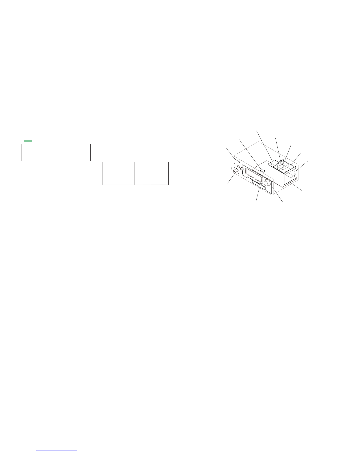
• Circuit Boards Location
DISPLAY board
USB board
MAIN board
STANDBY-A VIDEO PC board
D-VIDEO board
DIGITAL board
HEADPHONE board
POWER KEY board
DCDC board
TUNER (FM/AM)
TEMP-SENSOR board
THIS NOTE IS COMMON FOR PRINTED WIRING BOARDS AND SCHEMATIC DIAGRAMS.
(In addition to this, the necessary note is printed in each block.)
For Schematic Diagrams.
Note:
• All capacitors are in μF unless otherwise noted. (p: pF)
50 WV or less are not indicated except for electrolytics
and tantalums.
• All resistors are in and ¼ W or less unless otherwise
specifi ed.
• f : internal component.
• 2 : nonfl ammable resistor.
• 5 : fusible resistor.
• C : panel designation.
Note:
The components identifi ed by mark 0 or dotted
line with mark 0 are
critical for safety.
Replace only with part
number specifi ed.
Note:
Les composants identifi és
par une marque 0 sont
critiques pour la sécurité.
Ne les remplacer que
par une piéce portant le
numéro spécifi é.
For Printed Wiring Boards.
Note:
• X : Parts extracted from the component side.
• f : internal component.
•
: Pattern from the side which enables seeing.
Caution:
Parts face side:
(SIDE A)
Pattern face side:
(SIDE B)
Parts on the parts face side seen from
the parts face are indicated.
Parts on the pattern face side seen
from the pattern face are indicated.
• Abbreviation
CND
: Canadian model
ECE : Continental European, East European
and Russian models
• A
: B+ Line.
• B : B– Line.
• Voltages and waveforms are dc with respect to ground
under no-signal (detuned) conditions.
no mark
: FM
• Voltages are taken with VOM (Input impedance 10 M).
Voltage variations may be noted due to normal production
tolerances.
• Waveforms are taken with a oscilloscope.
Voltage variations may be noted due to normal production
tolerances.
• Circled numbers refer to waveforms.
• Signal path.
F : TUNER (FM/AM)
f : TUNER
L : VIDEO (AUDIO)
E : VIDEO
J : DVD (DIGITAL)
c : CD (ANALOG)
• Abbreviation
CND : Canadian model
ECE : Continental European, East European
and Russian models
STR-DH720/DH720HP
STR-DH720/DH720HP
2020
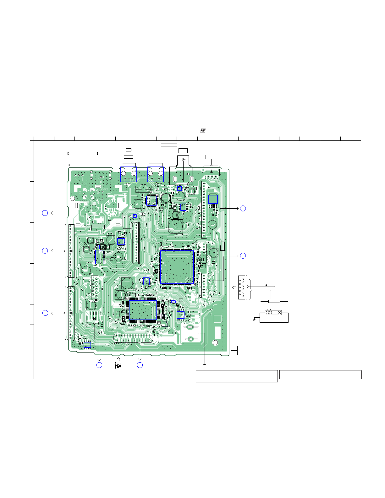
5-7. PRINTED WIRING BOARD – DIGITAL Board (Side A) –
• See page 19 for Circuit Boards Location. • : Uses unleaded solder.
1
A
B
C
D
E
F
G
H
I
J
K
2 3 4 5 6 7 8 9 10 11 12 13 14 15 16
IC2352 IC2351
IC2421
IC2805
IC2501
1
14
1528
IC2106
1
100
30
31
81
80
50
51
IC2105
IC2802
IC2804
133
132
88 45
44
176
89
1
IC2801
IC2020
IC2009
IC2006
1
12
13
24
2536
37
48
IC2803
IC2303
6
15
IC2010
O VCC O VCC
114
CN2103
CN2105
1 191 19
CN2114
20 1
CN2513
10
11
CN2002 (11P)
1
28
9
CN2003 (9P) (US, CND)
R2860
R2861
R2863
R2864
R2865
R2866
R2867
R2868
R2099
C2899
R2872
R2873
R2875
R2876
R2880
R2881
R2882
R2886
R2889
R2891
R2892
R2895
R2897
R2898
R2899
C2101
14
CN2501
C2114
C2119
C2501
C2502
C2503
C2504
C2506
C2507
C2508
C2509
FB2007
C2125
C2127
C2510
R2100
C2511
C2512
R2103
C2514
C2515
C2516
C2517
C2130
R2108
X2800
C2131
X2801
D2302
D2303
D2110
C2909
R2112
R2114
R2116
C2140
R2119
C2912
FB2603
C2913
FB2604
R2311
C2917
C2918
FB2608
C2531
R2509
R2123
L2007
R2124
L2008
FB2031
R2125
FB2801
FB2032
R2511
R2512
R2321
R2322
R2324
R2132
C2351
D2717
FB2043
C2354
C2355
C2358
C2359
R2912
C2361
R2917
R2918
R2919
R2920
R2921
R2923
C2370
R2925
R2928
R2158
R2540
R2159
R2541
R2351
R2930
R2160
R2354
R2356
R2357
R2358
R2938
R2941
R2172
R2173
R2949
R2759
R2957
R2958
R2959
R2960
R2962
R2963
R2197
RB2102
RB2103
RB2104
RB2105
RB2106
RB2107
RB2109
FB2884
FB2885
FB2886
FB2887
FB2889
FB2890
RB2119
FB2891
FB2892
JL2808
JL2809
JL2811
X2101
JL2812
C2011
C2206
C2013
C2208
C2016
C2402
CN2602
19
C2022
C2023
FB2101
C2413
R2007
C2418
C2421
R2011
C2422
C2424
D2018
R2015
FB2501
FB2502
C2814
JL2849
C2815
C2816
C2818
R2601
R2602
C2823
R2607
R2608
R2220
C2825
R2609
C2826
R2417
R2802
R2610
R2612
R2613
R2614
R2421
R2615
R2809
R2616
R2617
R2618
R2619
C2838
C2069
R2620
R2621
R2815
R2622
R2816
C2070
C2264
C2459
C2841
C2072
C2842
R2626
C2267
C2074
C2846
C2847
C2849
R2052
C2270
R2054
R2824
R2825
C2272
C2466
R2826
C2273
C2468
C2274
R2058
C2469
R2059
R2829
C2853
R2250
C2470
C2858
R2831
R2834
R2835
R2837
C2860
R2838
C2861
R2839
C2863
C2864
C2865
C2096
C2866
C2868
R2840
R2842
R2843
R2846
R2847
R2849
C2873
C2874
C2875
C2876
C2877
C2878
C2879
R2851
R2852
R2854
R2855
R2856
R2857
R2858
C2881
C2882
C2883
C2869
18
CN2603
R2929
R2186
25
24
1
2
CN2116
A2001
DIGITAL BOARD
(SIDE A)
X2101
J2301
TV
OPTICAL IN
OPTICAL
SAT/CATV IN
DIGITAL (ASSIGNABLE)
COAXIAL
BD/DVD IN
FLASH
PROGRAMMING
10
11
1
28
9
AM
ANTENNA
)0ȍ
COAXIAL
TUNER
(FM/AM)
(CHASSIS)
CN2003 : 9P (US, CND)
1-883-126-
11
(11)
ECE
C
MAIN
BOARD
CNP410
(Page 26)
D
TEMP-
SENSOR
BOARD
CN250
(Page 45)
E
DISPLAY
BOARD
CNS151
(Page 39)
G
D-VIDEO
BOARD
CN3003
(Page 31)
F
D-VIDEO
BOARD
CN3004
(Page 31)
CN2002 : 11P
A
STANDBY-A
VIDEO PC
BOARD
CN271
(Page 37)
B
MAIN
BOARD
CNP411
(Page 26)
(CHASSIS)
Note 1: IC2106 on the DIGITAL board cannot exchange with
single. When this part on the DIGITAL board is damaged,
exchange the entire mounted board.
Note 2: When the DIGITAL board (Suffi x-11) is replaced, refer
to “NOTICE OF BOARD VERSION CHECK” (page 4).
Ver. 1 .2
STR-DH720/DH720HP
STR-DH720/DH720HP
2121
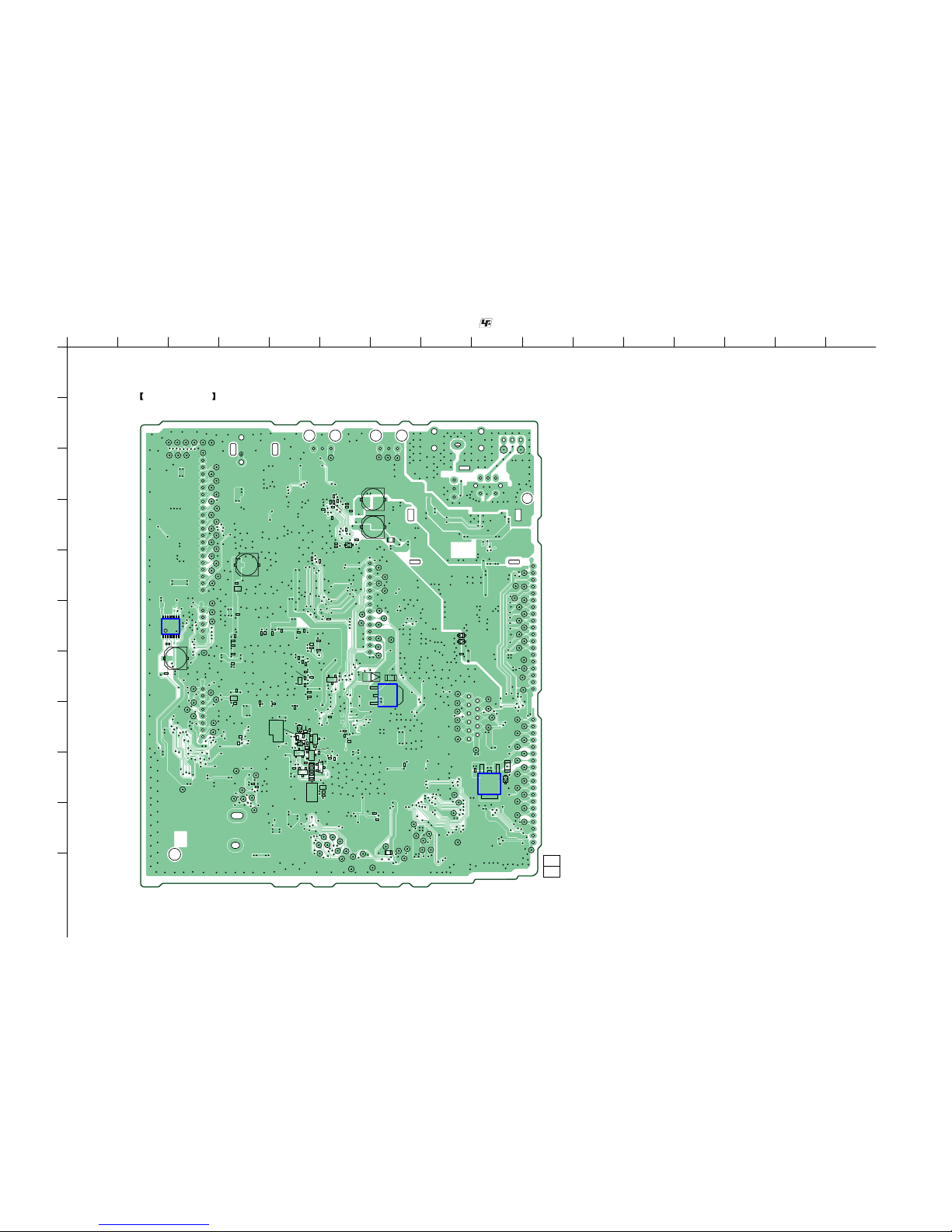
5-8. PRINTED WIRING BOARD – DIGITAL Board (Side B) –
• See page 19 for Circuit Boards Location. • : Uses unleaded solder.
1
A
B
C
D
E
F
G
H
I
J
K
2 3 4 5 6 7 8 9 10 11 12 13 14 15 16
B
E
B
E
B
E
B
E
BE
B
E
R2285
R2878
R2879
C2112
D2104
Q2702
Q2703
Q2704
R2104
Q2705
Q2706
C2905
R2111
C2910
C2721
C2722
D2701
FB2033
R2130
R2131
R2901
D2713
D2714
R2906
R2910
R2914
R2915
R2157
R2931
R2932
R2933
R2741
R2742
R2743
R2744
R2745
R2939
R2746
R2747
R2940
R2946
R2947
R2948
CL2001
CL2002
CL2003
CL2004
CL2005
CL2006
CL2007
R2951
CL2009
R2952
R2953
CL2200
CL2201
CL2203
CL2010
CL2204
CL2011
CL2012
CL2013
CL2014
CL2015
CL2016
CL2017
CL2018
CL2019
CL2210
CL2211
CL2212
CL2213
CL2020
CL2021
CL2022
CL2024
CL2025
CL2027
CL2028
CL2029
CL2030
CL2031
CL2032
CL2038
CL2040
CL2041
JL2021
JL2022
CL2045
CL2046
CL2047
CL2048
CL2049
CL2050
CL2051
CL2052
CL2053
CL2055
CL2056
C2003
CL2058
CL2059
Q2006
CL2061
CL2062
CL2063
CL2064
JL2814
CL2065
JL2815
CL2066
JL2816
CL2067
JL2817
CL2068
JL2818
CL2069
JL2819
C2015
CL2070
JL2820
CL2071
JL2821
CL2072
JL2822
CL2073
JL2823
CL2074
JL2824
CL2075
JL2825
C2021
JL2826
JL2827
JL2828
JL2829
D2003
D2004
CL2080
JL2830
JL2831
R2005
CL2082
JL2832
C2416
CL2083
JL2833
C2417
JL2834
CL2085
JL2835
CL2086
JL2836
CL2087
JL2837
C2033
CL2088
JL2838
JL2839
JL2840
CL2091
JL2841
D2019
CL2092
JL2842
CL2093
JL2843
CL2094
JL2844
CL2095
JL2845
JL2846
CL2097
JL2847
CL2098
JL2848
FB2311
R2211
C2817
C2819
JL2850
JL2851
JL2852
JL2854
C2820
JL2855
C2821
JL2856
C2822
JL2858
C2824
R2415
R2416
C2827
C2828
C2829
R2228
JL2863
R2807
C2830
C2831
JL2866
C2832
JL2868
JL2869
C2835
C2836
C2837
JL2870
JL2871
JL2872
JL2873
JL2874
C2840
JL2875
C2265
JL2876
C2266
JL2877
C2268
C2844
JL2878
C2269
C2845
R2050
C2462
R2053
C2850
C2851
C2852
C2854
C2855
R2251
C2856
C2857
C2859
C2862
C2093
R2841
R2844
C2870
C2871
C2872
R2850
R2853
C2884
IC2032
IC2107
3
12
IC2005
DIGITAL BOARD
(SIDE B)
1-883-126-
11
(11)

STR-DH720/DH720HP
STR-DH720/DH720HP
2222
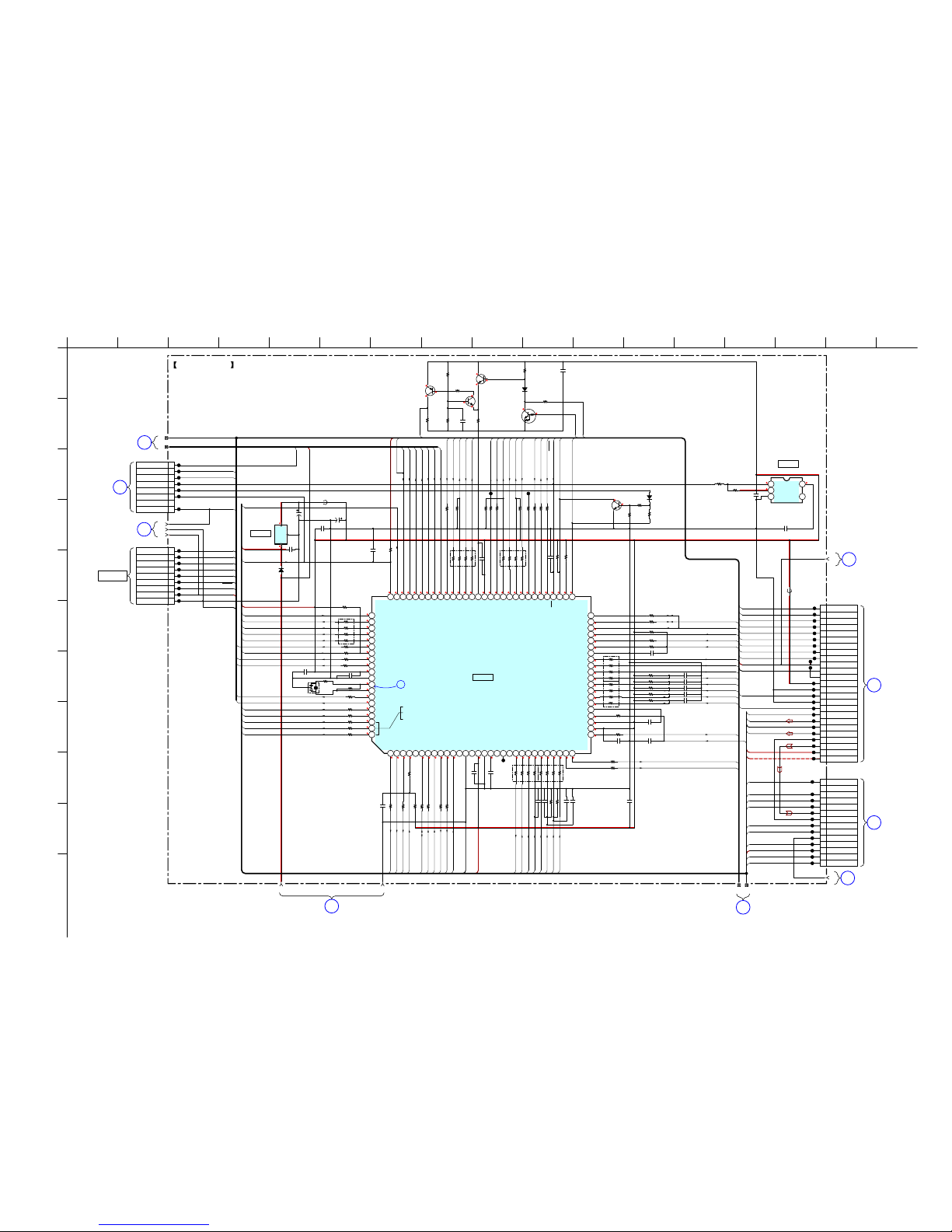
5-9. SCHEMATIC DIAGRAM – DIGITAL Board (1/4) –
• See page 46 for IC Block Diagrams. • See page 61 to 64 for IC Pin Function Descriptions.
1
A
B
C
D
E
F
G
H
I
J
K
2 3 4 5 6 7 8 9 10 11 12 13 14 15 16 17
DIGITAL BOARD (1/4)
7
8109
6
4
1
5
2
3
3.6
3.3
3.7
1.3
3.3
0
3.3
1.3
1.3
1.3
3.3
1.4
3.3
1.8
3.3
1.3
1.3
0
1.3 3.3 1.8 1.3 2 3.2 1.3 1.8 1.8 1.8 1.3 3.3 1.3 1.3 3.3 1.3 1.2 1.1 3.3 1.3 1.3 3.3 1.3 0 3.3 1.3 3.3 1.3
0
0
0
0
0
0
0
0
0
0
0
0
1.3
1.3
3.3 3.3 1.3 3.3 3.3 3.3 1.3 1.3 3.3 1.8 1.8 1.3 0 3.3 3.3 0 1.33.21.3
0
3.3
3.3
3.3
3.3
0
3.3 0 3.3 3.3
3.3
3.3 3.3
8
7
6
5
4
3
2
1
9
10
11
12
13
14
15
16
CEC
HDMI_RESET
HDMI_MISO/SCL
HDMI_MOSI/SDA
HDMI_SPDIF
MUTE
NON_LPCM
ARC_SPDIF
DCDC+6V
DCDC+4V
SD3
LRCK
BCK
MCK
GND
SD2
SD1
SD0
DSP_SPICLK
SBL/SBR_OUT
L/R_OUT
SBL/SBR_IN
DSP_NONAU
LRCLK_OUT
C/SW_IN
BCLK_OUT
C/SW1_OUT
DSP_ERROR
LRCLK_IN
MCLK_IN
DSP_INT
BCLK_IN
SL/SR_IN
SL/SR_OUT
UART_IN
DSP_MISO
DSP_MOSI
DSP_CS
DIR_IN
UART_IN
DSP_UART_SEL
DSP+3.3V
DSP_RST
DIR_RST
C2855
10
JL2809
JL2814
JL2812
JL2808
JL2811
10k
R2866
10k
R2835
10k
R2807
10k
R2867
10k
R2895
10k
R2899
10k
R2861
10k
R2910
10k
R2157
22
R2837
22
R2872
22
R284222R283922R2840
22
R2851
22R2846
22
R2850
22
R2838
22
R2825
22
R2826
22R2844
22R2843
22R2852
22R2809
22
R2802
22R2873
100
R2857
100
R2858
1k
R2876
100k
R2875
4.7k
R2053
4.7k
R2853
1M
R2856
0
R2854
C2851
0.1
C2816 0.1
C2864
0.1
C2856
0.1
C2847
0.1
C2844 0.1
C2849
0.1
C2840
0.1
C2826
0.1
C2825 0.1
C2827 0.1
C2846
0.1
C2835
0.1
C2836
0.1
C2853
0.1
C2817 0.1
C2838 0.1
C2845 0.1
C2857
0.1
C2819
0.1
C2850
0.1
C2820
0.1
C2828
0.1
C2862
0.1
C2832
0.1
C2821
0.1
C2858
0.1
C2859
0.1
C2822
0.1
C2831 0.1
C2829 0.1
C2852
0.1
C2818
0.1
C2861
0.1
C2830
0.1
C2863
0.1
C2824
0.1
C2860
0.1
C2854
0.1
C2823
0.1
C2837
0.1
C2842
7p
C2841
7p
FB2608
X2800
25MHz
1
2
C2905
220 4V
SELECT
1A
1B
1Y
2A
2B
2Y
GND 3Y
3B
3A
4Y
4B
4A
ST
VCC
10k
R2834
C2910
10
IC2801
ADSST-AVR-3010
1
SDDQM
2
MS0
3
SDCKE
4
VDD_INT
5
CLK_CFG1
6
ADDR0
7
BOOT_CFG0
8
VDD_EXT
9
ADDR110ADDR211ADDR312ADDR413ADDR5
14
BOOT_CFG1
15
GND
16
ADDR617ADDR7
18NC19
NC
20
ADDR821ADDR9
22
CLK_CFG0
23
VDD_INT
24
CLKIN
25
XTAL2
26
ADDR10
27
SDA10
28
VDD_EXT
29
VDD_INT
30
ADDR11
31
ADDR1232ADDR1733ADDR13
34
VDD_INT
35
ADDR18
36
RESETOUT/RUNRSTIN
37
VDD_INT
38
MOSI39MISO
40
SPICLK
41
VDD_INT
42
DPI_P05
43
DSP_CS
44
MD
45
46
47
48
49
50
51
52
53
54
55
56
57
58
59
60
61
62
63
64
65
66
67
68
69
70
71
72
73
74
75
76
77
78
79
80
81
82
83
84
85
86
87
88
VDD_EXT
NC
RESET_MAIN
VDD_INT
UART_OUT
UART_IN
LED
NC
NC
NC
NC
NC
VDD_EXT
NC
NC
NC
NC
VDD_INT
NC
NC
VDD_INT
NC
NC
VDD_INT
NC
WDTRSTO
NC
VDD_EXT
SL/SR_OUT
SL/SR_IN
BCLK_IN
OPTION_L/OPTION_R_OUT
FRONTHI_L/R_OUT
VDD_INT
NC
NC
NC
NC
NC
VDD_EXT
VDD_INT
L/R_OUT
MID/SW2_OUT
SBL/SBR_OUT
89
ZONE_L/R90VDD_INT91VDD_EXT92MCLK_IN93VDD_INT94C/SW1_OUT95C/SW_IN
96
A/D_2CH
97
LRCLK_IN98BCLK_OUT99LRCLK_OUT
100
L/R_IN
101
SBL/SBR_IN
102
VDD_INT
103
DIR_IN
104
VDD_EXT
105
VDD_INT
106
BOOT_CFG2
107
VDD_INT
108
AMI_ACK
109
GND
110
THD_M
111
THD_P
112
VDD_EXT
113
VDD_INT
114
VDD_INT
115
MS1
116
VDD_INT
117
WDT_CLKO
118
WDT_CLKIN
119
VDD_EXT
120
ADDR23
121
ADDR22
122
ADDR21
123
VDD_INT
124
ADDR20
125
ADDR19
126
VDDEXT
127
ADDR16
128
ADDR15
129
VDD_INT
130
ADDR14
131
AMI_WR
132
AMI_RD
133VDD_INT
134IRQ/GPIO
135FLAG1
136FLAG2
137MLBCLK
138FLAG3
139MLBDAT
140MLBDO
141VDD_EXT
142MLBSIG
143
VDD_INT
144TRST
145MLBSO
146EMU
147DATA0
148DATA1
149DATA2
150DATA3
151TDO
152DATA4
153VDD_EXT
154DATA5
155DATA6
156VDD_INT
157DATA7
158TDI
159SDCLK
160VDD_EXT
161DATA8
162DATA9
163DATA10
164TCK
165DATA11
166DATA12
167DATA14
168DATA13
169VDD_INT
170DATA15
171SDWE
172SDRAS
173RESET
174TMS
175SDCAS
176VDD_INT
GND
2.2k
R2868
2
3
4
5
6
7
8
9
10
11
12
13
14
15
16
17
18
19
20
RB2103
100
CN2513
20P
NC
1
CEC
RESET
MISO / SCL
MOSI / SDA
NON_LPCM
MUTE
HDMI_SPDIF
SD0
SD1
SD2
SD3
LRCK
BCK
GND
MCK
GND
ARC_SPDIF
DCDC+6V
DCDC+4V
JL2830
JL2831
JL2832
JL2833
JL2834
JL2835
JL2836
JL2837
JL2838
JL2839
JL2840
JL2841
JL2842
JL2843
JL2844
JL2845
JL2846
JL2847
JL2848
47
R2615
100R2626
FB2031
FB2032
330
R2617
470
R2618
220R2841
220
R2829
220
R2831
220
R2824
330R2847
330
R2849
DSP_MISO
DSP_SFLASH_HOLD
DSP_CS
DSP_SPICLK
DSP_MOSI
C2866
10
10k
R2879
10k
R2865
10k
R2898
10k
R2897
22
R2878
22
R2882
22
R2880
22
R2864
22
R2863
C2865
0.1
FB2889
0uH
2.2k
R2881
IC2802
W25Q16BVSSIG
CE#SOWP#
Vss SI
SCK
HOLD#
Vdd
DSP
IC2801
EEPROM
IC2802
DIGITAL
BOARD
(2/4)
(Page 23)
1
DIGITAL
BOARD
(2/4), (3/4)
(Page 23),
(Page 24)
2
DIGITAL
BOARD
(2/4)
(Page 23)
3
DIGITAL
BOARD
(3/4)
(Page 24)
4
DIGITAL BOARD (3/4)
(Page 24)
5
D-VIDEO
BOARD
(1/4)
CN3003
(Page 33)
A
IC2032
TC74VHC157FT (EKJ)
IC B/D
SIGNAL SELECTOR
IC2032
Ver. 1 .1
STR-DH720/DH720HP
STR-DH720/DH720HP
2323
5-10. SCHEMATIC DIAGRAM – DIGITAL Board (2/4) –
• See page 42 for Waveforms. • See page 59 and 60 for IC Pin Function Descriptions.
1
A
B
C
D
E
F
G
H
I
J
K
2 3 4 5 6 7 8 9 10 11 12 13 14 15 16 17
DIGITAL BOARD (2/4)
15
1
11 12
6
5
4
2
3
DIGITAL BOARD
(1/4), (3/4)
(Page 22), (Page 24)
2
13 14
3.3
6
0
0
0
3.3
0
0
3.3
3.3
0
0
3.3
1.8
1.8
3.3
0
0
0
3.3
3.3
3.3
0.8 0 3.3 3.3 3.3 3.3 0 0 3.3 0 0 0 3.3 0 3.3 0 0 0 1.8 0 3.3 3.3 3.3 3.3 3.3 3.3 03.3
0
3.3
3.3
3.3
0
3.3
0
3.3
3.3
3.3
3.3
3.3
3.3
0
3.3
3.3
03.300.90.90.601.5001 10001003.33.3 23.3
3.3
3.3
3.3
0
3.3
0
3.3
1.6
2.7
3.3
2.7
3.3
3.3
3.3
0
3.3
0
1
2
3
4
5
6
7
8
9
10
11
12
13
14
15
2
3
4
5
6
7
8
9
10
11
12
13
14
VSEL_2
VSEL_1
V_MUTE_1
COMP_SW2
POWER_DET
SIRC
DIR_RST
DCDC+6V
USB_SPDIF
VSEL_2
VSEL_1
V_MUTE_1
SO
V2_AUDIO_R
-7V
+7V
DA
CK
BRIG_RY
MD2
FL_CLK
FL_DATA
FL_CLK
FL_LAT
INPUT
AD_KEY1
AD_KEY2
VOLUME
FL_GND
DCDC+4V
SIRC
HDMI_RESET
CEC_OUT
VIDEO2_AGND
TONE
FLASH_CLK
SI
DIR_SIGNAL
DIR_INT
MODEL
V2_AUDIO_L
DCAC_IN
FUSE_DET
COMP_DET
FL/FR_RY
C/SL/SR_RY
STBY_SUPPLY
+3.3V_STBY
COMP_SW2
MD0
DIR_CE
DCAC_MUTE
IISD
COMP_DET
STOP
VERSION
RESET
DSP_SFLASH_HOLD
SO
HDMI_MISO/SCL
HDMI_MOSI/SDA
CEC_IN
CEC_OUT
CEC
CEC_IN
POWER_DET
AD_KEY1
AD_KEY2
TONE
VOLUME
INPUT
DCAC_MUTE
LIMITER
TUNER_RDS_DATA
TUNER_CE
TUNER_MISO
SBL/SBR_RY
E2P_DATA
E2P_CLK
VCC_3.3V
NO_USE
SW_RY
HP_RY
HP_DET
EVOL_DATA
EVOL_CLK
DAC_MUTE
DAC_LAT
COM_DATA
PROTECTOR
COM_CLK
POWER_RY
STOP
STBY_SUPPLY
DIR_MPO0
DIR_XSTATE
DIR_MISO
DIR_MISO
DSP_ERROR
3.3V
DSP_SPICLK
DSP_MOSI
DSP_MISO
DSP_INT
DSP_RST
DSP_NONAU
DSP_CS
DSP_UART_SEL
VERSION
MODEL
SI
POWER_RY
FL_DATA
FL_LAT
RECTIFIER_TEMP
TEMP_SENSOR_2
TEMP_SENSOR_1
DSP_SEL
+3.3V_STBY
C2417
0.1
X2101
4MHz
C2023
10
RB2102
100
Q2705
CEC DATA SWITCH
RT1N141C-TP-1
Q2703
CEC DATA SWITCH
2SC3052EF-T1-LEF
Q2704
CEC DATA SWITCH
2SC3052EF-T1-LEF
Q2702
CEC DATA SWITCH
ISA1235AC1-T112-1EF
C2112
0.1
FB2311
0uH
FB2101
0uH
C2021
0.47
IC2107
BA33BC0FP-E2
CL2092
CL2087
CL2097
CL2083
CL2093
CL2088
CL2091
CL2085
CL2098
CL2080
CL2094
CL2086
CL2095
CL2053
CL2047
CL2031
CL2027
CL2024
CL2059
CL2040
CL2049
CL2041
CL2021
CL2030
CL2046
CL2051
CL2058
CL2038
CL2025
CL2056
CL2210
CL2211
CL2212
C2459 0.1
R2007 1M
RB2109
100
CL2052
R2324
10kR2131
10k
R2228
10k
R2744
10k
R2132
10k
R2747
10kR2054
100
R2250
10k
R2130
2.2k
R2160
OUT
VDD
VSS NC
CD
RB2104
100
100
RB2106
RB2107
100
R2321
C2206 1000p
C2208 0.1
CN2116
25P
FL_CLK
FL_DIN
FL_LAT
INPUT_JOG
AD1
AD2
SIRCS
PW_SW
VOL_JOG
+3.9V_DCDC
FL_GND
FL_GND
+3.3V(STBY)
DGND
TONE_JOG
D_GND
MIC_MUTE
DCAC_IN
V2_AUDIO_L
A_GND
V2_AUDIO_R
V_GND
V2_VIDEO
+7V
-7V
CL2061
CL2055
CL2050
R2906
R2197
100
R2114
R2607
100R2119
R2609
100
R2620
100
R2621
R2612
100R2123
R2616
100
R2622
100R2124
R2619
100
100
100
100
220
R2746
470
R2285
1k
R2741
1.5k
R2100
22k
R2742
22k
R2743
10kR2015
C2130 0.1
C2101
0.1
C2127
0.1
C2418 0.1
C2413
0.1
C2416
0.1
C2469
0.1
C2462
0.1
C2721
0.1
C2722
0.1
C2402 0.1
27k
R2745
10k
R2158
C2119
0.1
R2613
JL2849
C2022
470 16V
C2131
47 16V
C2883
4.7
C2884
4.7
D2019
DA2J10100L
2.2k
R2608
2
3
4
5
6
7
8
JL2850
JL2851
JL2852
JL2854
JL2855
JL2856
JL2858
CN2603
8P
NC
1
POWER_RY
STOP
USB_UP_MU_MD2
USB_UP_MU_RST
MU_SI/RX
MU_SO/TX
USB_SPDIF
D2714
1SR154-400TE-25
10k
R2915
100
R2917
100
R2918
100
R2919
100R2920
CN2103
14P
NC
1 COMP_SW2
V_MUTE_1
VSEL_1
VSEL_2
VIDEO2
VIDEO2_VGND
COMP_DET
STOP
POWER_RY
STBY_SUPPLY
+3.3V STBY
VERSION
MODEL
100
R2923
C2466 1000p
C2125 1000p
0
R2186
4.7k
R2928
RB2119
100
100R2929
C2909 0.1
10k
R2931
R2112
2.2k
2.2k
2.2k
100
100
R2614
R2220
R2921
100
100
RB2105
100
100R2930
R2052
10k
10k
10k
IC2105
MB90F058PF-G-JNE1
1
SBL-SBR_RY2BRIDGEABLE_RY3HP_RY4HP_DET5NO_USE6E2P_DATA7E2P_CLK8TUNER_SD9TUNER_MOSI10TUNER_CLK11TUNER_RDS_CLK12NO_USE13NO_USE14NO_USE15VCC_3.3V16VSS_GND17C
18 19 20
MU_BUSY21TUNER_LAT22TUNER_RDSDATA23TUNER_MISO24VERSION25MODEL26TEMP_SENSOR_127TEMP_SENSOR_228RECTIFIER_TEMP
29
FL_LAT
30
FL_DATA
31
FL_CLK
32
AVCC_3.3V
33
AVRH
34
LIMITER
35
AVSS
36
AD_KEY_1
37
AD_KEY_2
38
TONE_JOG
39
INPUT_JOG
40
VOL_JOG
41
DCAC_MUTE
42
HDMI_RST/VMCOM_RST
43
HDMI_CECOUT
44
VSS_GND
45
POWER_KEY
46
SIRCS
47
HDMI_CECIN
48
HDMI_MISO/ NO USE
49
HDMI_MOSI/ SDA
50
NO USE/ SCL
51
MD252MD153MD0
54
RST
55
DSP_MISO56DSP_MOSI
57
DSP_SPICLK
58
HDMI_CNVSS
59
SI
60
SO
61
FLASH_CLK
62
UART_SEL
63
DSP_SPICS
64
DSP_SFLASH_HOLD
65
DVCC
66
DVSS
67
DSP_RST
68
DSP_INT
69
DSP_SEL
70
DSP_NPCM
71
DSP_ERROR
72
DIR_MPO073DIR_MPO1
74
DIR_SIGNAL
75
DIR_RST
76
DIR_CE
77
PROG/ DIR_XSTATE
78
PROG/ DIR_MISO
79
FUSE_DET
80
STOP
81
COMP_DET
82
V_COMP_SW2
83
V_MUTE
84
V_SEL_SW1
85
V_SEL_SW2
86
POWER_RY
87
PROTECTOR
88
COM_CLK
89
COM_DATA
90
VCC_3.3V
91
VSS_GND
92
X1(X_OUT)
93
X0(X_IN)
94
DAC_LATCH
95
DAC MUTE
96
EVOL_CLK
97
EVOL_DATA
98
C/SL-SR_RY
99
FRONT_SPK_A_RY
100
PREOUT_SW_RY
10k
R2953
C2912
0.1
C2913
0.1
C2917
0.1
C2918
0.1
10kR2939
D2701
RB751V-40TE-17
1k
R2951
1k
R2952
Q2006
2SC3052EF-T1-LEF
470
R2914
470
R2251
CL2213
100
R2932
1M
R2116
1M
R2322
MD0
MD2
SI
SO
FLASH_CLK
RESET
GND
3.3V
DIR_MISO
CN2602
9P
GND
3.3V
RESET
CLK
SO
SI
PROG
MD2
MD0
CL2007
CL2005
CL2004
CL2003
CL2001
CL2006
CL2002
CL2010
CL2009
1
2
3
4
5
6
7
8
9
VCC
GND
OUT
16
17
18
19
20
21
22
23
24
25
5
43
2
1
10k
SYSTEM CONTROL
IC2105
DIGITAL
BOARD
(1/4)
(Page 22)
1
DIGITAL BOARD
(1/4)
(Page 22)
3
D-VIDEO
BOARD
(1/4)
CN3004
(Page 33)
B
FLASH
PROGRAMMING
DIGITAL BOARD (3/4)
(Page 24)
6
DIGITAL BOARD (4/4)
(Page 25)
7
DIGITAL BOARD
(3/4)
(Page 24)
8
DISPLAY
BOARD
CNS151
(Page 40)
C
STANDBY-A
VIDEO PC
BOARD
CN271
(Page 38)
D
DATA SWITCH
IC2020
S-80929CNMC-G8ZT2G
RESET SIGNAL GENERATOR
IC2020
+3.3V REG
IC2107
I2C/RDSI
1

STR-DH720/DH720HP
STR-DH720/DH720HP
2424
5-11. SCHEMATIC DIAGRAM – DIGITAL Board (3/4) –
• See page 42 for Waveforms. • See page 46 for IC Block Diagrams.
1
A
B
C
D
E
F
G
H
I
J
K
2 3 4 5 6 7 8 9 10 11 12 13 14 15 16 17
DIGITAL BOARD (3/4)
23
21
18
20
19
15
11
12
7
810 9
22
24
17
16
2
3
1.4 3.3
1.8
3.3
3.30
3.3
3.3
3.3
3.3 1.3
1.4 3.3
1.8 1.3
3.3 1.3
3.3
1.8
1.2
2.7
2.6
1.21.2
1.3
3.3
3.3
3.3
3.3
1.7 1.8 1.80
0
3.3
3.3
0
2.8
2
0
0
2.6
3.3
0 3.3 1.3 0 3.3 0 0
0
0
0
0
3.3
0
0
0
0
0
0
02.452.403.31.81.8
0
3.3
0 3.3
0
3.3
3.3
3.3 3
0
3.1
0
3.3
6 3.7
6.2 6.2
1.1 1
0.9
1
3.3 3.9 3.9
VCC
OUT
GND
VCC
OUT
GND
123465
BCLK_IN
SBL/SBR_IN
C/SW_IN
SL/SR_IN
DIR_SIGNAL
SD3
SD2
SD1
SD0
LRCK
BCK
MCK
NON_LPCM
MUTE
DIR_IN
DIR_RST
DSP_SEL
HDMI_SPDIF
ARC_SPDIF
USB_SPDIF
DSP_NONAU
MCLK_IN
MCK
LRCLK_IN
C/SW1_OUT
L/R_OUT
FL_GND
SBL/SBR_OUT
SL/SR_OUT
DIN4/DNC
DIN2
DSP_ERROR
DIR_XSTATE
DIR_INT
DIR_CE
DIR_MISO
DIR_MPO0
C2361
0.1
C2358
0.1
IC2351
TORX147L(SONY)
J2301
1P
COAXIAL
BD/DVD IN
FB2604
C2815
7p
C2814
7p
X2801
24.576MHz
C2871
10
C2868
10
FB2603
10k
R2901
FB2033
21A102
IC2804
TC74VHC157FT (EKJ)
1
SEL
2
A0
3
B0
4
Y0
5
A1
6
B1
7
Y1
8
GND9Y2
10
B2
11
A2
12
Y3
13
B3
14
A3
15
ST
16
VCC
FB2007
21A102
R2211
R2111
10k
47k
R2311
8
7
6
5
4
3
2
1
CK
D
Q
GND Q
CLR
PR
VCC
FB2801
0uH
10k
R2125
10k
R2011
10k
R2108
10kR2099
100
R2059
100
R2351
100
R2354
100
R2759
220
R2816
330
R2601
330
R2602
470
R2356
1k
R2104
47k
R2357
470k
R2358
1M
R2815
R2415
R2416
0
0
R2417 0
C2268
4700p
C2069
0.01
C2272
0.1
C2354
0.1
C2881
0.1
C2875
0.1
C2072
0.1
C2870
0.1
C2273
0.1
C2011 0.1
C2274
0.1
C2351
0.1
C2269
0.068
680
R2050
C2114
22
C2370
10
D2104
DA2J10100L
220ohm
FB2884
220ohm
FB2885
L2007
10uH
C2874
10
C2879
0.022
C2873
10
IC2803
MP2301ENE-LF-Z
1
BST
2
VIN
3
SW
4
GND5FB
6
COMP
7
EN
8
SS
9
TAB
C2876
0.1
C2878
0.1
C2899
0.1
1kR2892
1k
R2891
C2270
0.1
C2877
1000
6.3V
220ohm
FB2886
L2008
10uH
FB2887
0uH
JL2868
JL2869
JL2870
JL2871
JL2872
22k
R2173
IC2010
SI-3010KM-TLS
ENINGND
OUT
FB
GND
10k
R2172
D2717
DA2J10100L
FB2891
0uH
C2355
22
6.3V
47
R2925
IC2303
TC7WHU04FU (TE12R)
IN1
OUT3
IN2
GND OUT2
IN3
OUT1
VCC
C2074
10
10k
R2103
C2070
0.1
100
R2912
IC2805
TC74VHC08FT (EL)
1
A0
2
B0
3
Y0
4
A1
5
B1
6
Y1
7
GND8Y2
9
B2
10
A2
11Y3
12
B3
13
A3
14
VCC
FB2892
0uH
IC2009
TC7WH74FK
Q2706
RT1N141C-TP-1
MUTE SWITCH
C2470
10
10k
10k
R2933
C2013 100 16V
C2869
220 4V
C2872
220 4V
C2265
100
16V
C2266
100
16V
C2264
100 16V
C2267 100 16V
1k
R2941
C2093
470p
1M
R2005
IC2006
PCM9211PTR
ERROR/INT0
NPCM/INT1
MPIO_A0/HDMI_MCK
MPIO_A1/HDMI_BCK
MPIO_A2/HDMI_LRCK
MPIO_A3/SD0
MPIO_C0/X_STATE
MPIO_C1/SD1
MPIO_C2/SD2
MPIO_C3/SD3
MPIO_B0/SI_C
MPIO_B1/SI_D
13
SI_E
14
SI_F
15
MPO0
16
MPO1/DIR_INT
17
DOUT
18
LRCK
19
BCK
20
SCKO
21
DGND
22
DVDD
23
MDO/ADR0
24
484746454443424140393837
MDI/SDA
25
MC/SCL
26
MS/ADR1
27
MODE
28
RXIN7/HDMI_SPDIF
29
RXIN6/HDMI_ARC
30
RXIN5/USB_SPDIF
31
RXIN4/TV OPT IN
32
RXIN3/SAT/CATV OPT IN
33
RXIN2/DVD_Coaxial In
34
RST
35
RXIN1
36
12
11
10
9
8
7
6
5
4
3
2
1
VDDRX
RXIN0
GNDRX
XTI
XTO
AGND
VCC
FILT
VCOM
AGNDAD
VCCAD
VINL
VINR
10k
R2940
C2359
100
16V
10k
R2886
3.3k
R2860
680
R2889
0
R2946
0
R2949
0
R2947
0
R2948
C2468 0.1
DIN1
100
R2959
100
R2958
100R2960
DIN3 100R2957
470
R2610
75
R2855
1.1V
4815263
7
DIGITAL OPTICAL
RECEIVE
IC2351
IC2352
TORX147L(SONY)
DIGITAL OPTICAL
RECEIVE
IC2352
IC B/D
WAVE SHAPER
IC2303
IC B/D
SIGNAL SELECTOR
IC2805
SCHMITT TRIGGER
IC2009
DIGITAL AUDIO
INTERFACE
RECEIVER
IC2006
MUTING
IC2804
+3.3V REG
IC2010
POWER OPERATION AMP
IC2803
OPTICAL
SAT/CATV
IN
DIGITAL
(ASSIGNABLE)
DIGITAL
BOARD
(2/4)
(Page 23)
DIGITAL
BOARD
(4/4)
(Page 25)
DIGITAL
BOARD
(1/4)
(Page 22)
DIGITAL BOARD (1/4)
(Page 22)
DIGITAL
BOARD
(1/4), (2/4)
(Page 22),
(Page 23)
DIGITAL
BOARD
(2/4)
(Page 23)
DIGITAL
BOARD
(4/4)
(Page 25)
DIGITAL
BOARD
(4/4)
(Page 25)
5
6
4
8
10
11
2
9
IC B/D
IC B/D
2
3
OPTICAL
IN
TV
Ver. 1 .1

STR-DH720/DH720HP
STR-DH720/DH720HP
2525
1
A
B
C
D
E
F
G
H
I
J
K
2 3 4 5 6 7 8 9 10 11 12 13 14 15 16 17
DIGITAL BOARD (4/4)
20
23
16
17
21
22
24
19
18
13
14
3.3
5
1.3
7
9
15
6.7
0 0 0 3.3 1.3 1.3 1.8 1.3 3.3 1.8 1.8 1.8
0 2.45 2.4 2.4 2.4 2.4 2.4 2.4 2.4 0 5
V2_AUDIO_L
V2_AUDIO_R
VIDEO2_AGND
DCAC_IN
1
2
3
4
5
6
7
8
9
I
O
COM
1
2
3
4
765432113 12 11 10 8914
22 23 242526 27 2816 17 18 19 212015
DAC_MUTE
LRCLK_OUT
BCLK_OUT
MCK
DIN4/DNC
DIN1
DIN2
DIN3
DAC_LAT
TEMP_SENSOR_2
TEMP_SENSOR_1
TUNER_CE
DA
CK
IISD
FUSE_DET
+15V_TUNER
SBL
SBR
SL
SR
C
SW
VCC_3.3V
E2P_DATA
E2P_CLK
NO_USE
TUNER_MISO
+7V
COM_DATA
COM_CLK
TUNER_RDS_DATA
R
L
C2510
0.1
D2003
1SS367-T3SONY
D2004
1SS367-T3SONY
FB2502
0uH
C2508
0.1
FB2501
0uH
C2511
100p
C2512
10
C2421
1
CL2204
CL2203
CL2201
CL2200
C2506
0.1
C2502
0.1
C2501
10
10k
R2421
R2511
10k
10k
R2512
D2018
1SS367-T3SONY
L_CH
Vcc
R_CH
GND
SD
CE
DI
CLK
TUNER_MISO/ DO
CN2003
9P
IC2005
KIA7809AF/API
C2015
0.47
JL2021
JL2022
JL2821
JL2822
JL2823
JL2824
JL2825
JL2826
JL2827
C2517
1000p
C2531
1000p
C2514
0.01
C2516
0.01
C2515
0.1
C2424
0.1
C2504
0.1
C2003
0.1
33
R2509
22k
R2540
33k
R2541
C2503
220 4V
C2016
47 16V
CN2501
4P
+3.3V
DGND
TEMP_SENSOR_1
TEMP_SENSOR_2
FB2043
0uH
C2422
4.7
D2713
DA2J10100L
FB2890
0uH
IC2421
TK11150CSCL-G
ON/OFF
GND
NoiseBypass
VOUT
VIN
C2033
0.1
C2882
100
10V
C2507
10 16V
C2509
10
16V
C2096 100 16V
10k
R2938
2
3
4
5
6
7
8
9
10
11
12
13
14
15
16
17
18
19
BRIG_RY
HP_DET
+15V_TUNER
EVOL_DATA
EVOL_CLK
C/SL/SR_RY
SBL/SBR_RY
FL/FR_RY
SW_RY
HP_RY
LIMITER
PROTECTOR
RECTIFIER_TEMP
CL2011
CL2074
CL2073
CL2075
CL2071
CL2072
CL2070
CL2067
CL2066
CL2069
CL2063
CL2062
CL2065
CL2064
CL2068
CL2082
D2110
DA2J10100L
D2302
MC2838-T112-1
D2303
MC2838-T112-1
CN2105
19P
NC
1
+3.3V
DGND
REG_TEMP
HP_RY
PREOUT_SW_RY
FL-FR_RY
SBL-R_RY
BRIDGEABLE_RY
C-SLR_RY
PROTECTOR
LIMITER
HP_DET
+15V_TUNER
EVOL_DATA
EVOL_CLK
VIDEO2_R
A_GND
VIDEO2_L
JL2878
IC2501
WM8768GEDS/R
MODE
MCK
BCK
LRCK
DVDD
DGND
DIN1
DIN2
DIN3
DIN4/DNC
ML/I2S
MC/IWL
MD/DM
MUTE
TEST_REF
VREF_N
VREF_P
VMID
VO4L
VO4R
VO1L
VO1R
VO2L
VO2R
VO3L
VO3R
AGND
AVDD
1k
R2962
1k
R2963
1
2
3
4
5
6
7
8
9
10
11
12
13
14
15
16
17
18
LRCK/LOUT
BCLK/ROUT
-7V
+7V
CL2032
CL2017
CL2015
CL2013
CL2022
CL2019
CL2016
CL2045
CL2028
CL2048
CL2012
CL2020
CL2018
CL2014
CL2029
JL2863
CN2114
19P
+7V
-7V
L_IN
AGND
AGND
R_IN
FR_OUT
FL_OUT
SW_OUT
C_OUT
SR_OUT
SL_OUT
SBR_OUT
SBL_OUT
DCAC_IN
TUNER_R
TUNER_L
19
NC
10k
R2058
R2159
3.3k
C2140
0.1
IC2106
CAT24C64WI-GT3
1
A0
2
A1
3
A2
4
GND
5
SDA
6
SCL
7
WP
8
VCC
EEPROM
IC2106
+9V REG
IC2005
IC B/D
D/A CONVERTER
IC2501
LRCK/LOUT
BCLK/ROUT
+5V REG
IC2421
DIGITAL BOARD
(2/4)
(Page 23)
DIGITAL BOARD
(3/4)
(Page 24)
DIGITAL BOARD
(3/4)
(Page 24)
DIGITAL BOARD
(3/4)
(Page 24)
9
10
11
7
MAIN
BOARD
(3/4)
CNP410
(Page 29)
F
TEMP-SENSOR
BOARD
CN250
(Page 45)
E
MAIN
BOARD
(3/4)
CNP411
(Page 29)
G
6
COAXIAL
GND
AM
2
1
8
4
TN1
5
VCC +9V
SD
RCH OUT
DI
DO/ST/SD
9
3
LCH OUT
ANTENNA
CL
7
CE
FM 75
10
RDS DATA
11
RDS INT
(ECE)
10
11
CN2002
11P
RDS_INT
RDS_DATA
(US, CND)
(ECE)
I2C/RDSI
JL2828
JL2829
5-12. SCHEMATIC DIAGRAM – DIGITAL Board (4/4) –
• See page 46 for IC Block Diagrams.
Note 1: IC2106 on the DIGITAL board cannot exchange with
single. When this part on the DIGITAL board is damaged,
exchange the entire mounted board.
Note 2: When the DIGITAL board (Suffi x-11) is replaced, refer
to “NOTICE OF BOARD VERSION CHECK” (page 4).
Ver. 1 .2
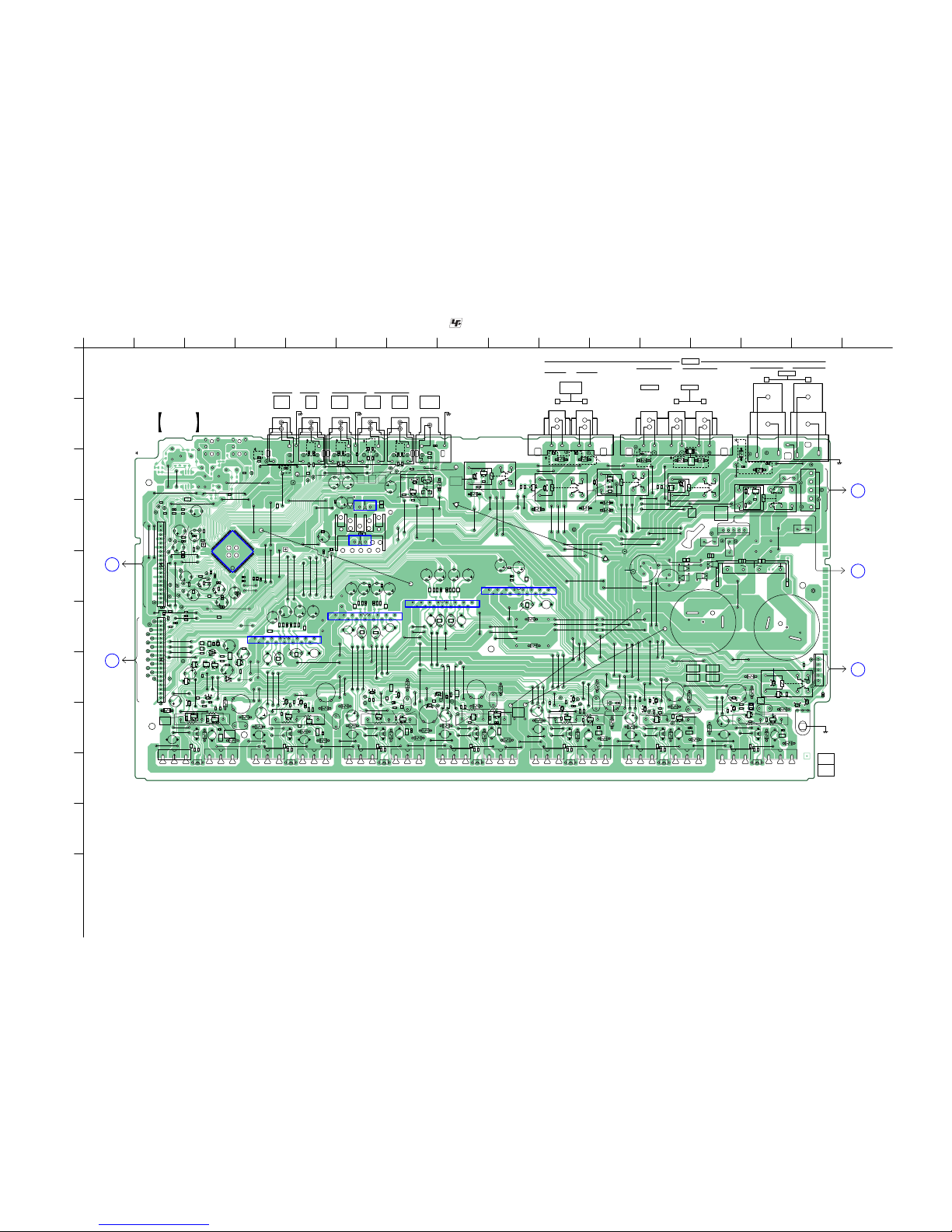
STR-DH720/DH720HP
STR-DH720/DH720HP
2626
5-13. PRINTED WIRING BOARD – MAIN Board –
• See page 19 for Circuit Boards Location. • : Uses unleaded solder.
1
A
B
C
D
E
F
G
H
I
J
K
2 3 4 5 6 7 8 9 10 11 12 13 14 15 16
132 132 132 132
132
132
132
132 132 132 132 132
132 132
EB EB
EB
EB
EB
EB
EB
EB
EB
EB
EB
EB
EB
EB
JR
JR
JR
JR
JR JR JR
JR
JR
JR
JR
JR
B
E
B
E
B
E
B
E
B
E
B
E
B
E
B
E
B
E
B
E
B
E
B
E
B
E
B
E
B
E
B
E
B
E
B
E
B
E
B
E
JR
JR
B
E
B
E
B
E
B
E
B
E
B
E
IO
IC352
IO
IC350
IC801
15
14
2
1
15
14
2
1
15
14
2
1
15
14
2
1
IC701
IC601
IC501
IC400
20
21
416040
61
80 1
Q654
HS921
Q851
Q852
Q853
Q854
HS350
15
CNP920
R609
R610
R612
R613
R809
R810
R812
R813
LP401
R628
R629
L678
R828
R829
L878
C408
C603
C605
C607
C608
C609
C803
C610
C805
C612
C807
C808
C809
C810
R659
C812
R660
R662
R663
R859
C629
R860
R862
R863
C829
R678
R679
F910
R878
F911
R879
F912
F913
C458
C653
C655
C657
C658
C659
Q503
Q504
C853
C660
C855
C662
C857
C858
C471
C859
Q701
Q702
Q703
Q704
C860
C862
C679
RR11
RR12
RR13
RR14
RR15
RR17 RR18
C879
L728
J401 J405
Q551
Q552
Q553
Q554
R302
Q751
Q752
Q753
Q754
L550
R513
LP401
R709
R710
R712
R713
R728
R729
L778
R920
R545
R351
R546
R356
C703
C705
C707
R550
C320
C708
R551
C709
R553
R361
C325
R558
C710
R365
C712
R759
C912
C913
R567
R377
R760
R762
R763
C729
RY301
C545
C351
C546
C547
C353
R778
R779
C550
C552
C555
C557
C558
C559
C753
C560
C561
C755
C757
C758
C759
Q601
Q602
Q603
Q604
C760
C762
Q801
Q802
RY920
C779
D921
L628
L828
Q651
Q652
Q653
TB502
TB503
ET300
J409
C321
C380
C381
C382
C383
C384
C385
C386
C387
C930
C931
JWH603
JWH600
JWH601
JW758
JW770
JW796
JW797
JW603
JW609
JW803
JW612
JW807
JW624
JW628
JW833
JW660
JW665
JW670
JW671
JW672
JW674
JW677
JW691
JW709
JW710
JW713
JW721
JW728
JW741
JW742
JW743
JW746
JW757
JW762
JW775
JW787
JW788
JW601
JW801
JW804
JW611
JW613
JW815
JW625
JW633
JW641
JW643
JW646
JW707
JW708
JW731
JW732
JW751
JW752
JW755
JW759
JW760
JW773
JW783
JW792
JW604
JW605
JW621
JW821
JW824
JW635
JW636
JW639
JW645
JW650
JW682
JW689
JW693
JW738
JW740
JW753
JW756
JW763
JW768
JW772
JW774
JW782
JW805
JW614
JW809
JW617
JW623
JW627
JW629
JW820
JW630
JW637
JW642
JW649
JW654
JW666
JW667
JW673
JW694
JW695
JW718
JW739
JW744
JW747
JW766
JW790
JW795
JW648
JW651
JW656
JW659
JW661
JW663
JW690
JW717
JW719
JW722
JW745
JW761
JW764
JW769
JW776
JW779
JW780
JW784
JW798
JW600
JW606
JW607
JW610
JW615
JW619
JW620
JW622
JW816
JW818
JW826
JW638
JW832
JW644
JW652
JW657
JW658
JW662
JW664
JW668
JW678
JW683
JW684
JW685
JW688
JW692
JW504
JW700
JW704
JW712
JW716
JW724
JW726
JW729
JW749
JW767
JW777
JW778
JW781
JW785
JW791
JW793
JW602
JW608
JW800
JW802
JW618
JW811
JW626
JW631
JW632
JW634
JW640
JW655
JW669
JW676
JW680
JW681
JW686
JW687
JW698
JW699
JW703
JW705
JW711
JW714
JW715
JW720
JW725
JW733
JW734
JW736
JW737
JW750
JW697
JW701
JW616
JW808
JW813
JW647
JWH604
JWH602
TB504
JW653
RY350
RY355
RY360
RY365
RY375
JW819
JW675
119
CNP410
1
19
CNP411
1
5
CNP930
1
5
CN391
JW679
D326
D327
D910
D911
D912
D913
Q661
Q662
Q861
Q862
Q301
Q320
Q321
Q323
Q324
Q325
Q711
Q712
Q920
Q350
Q355
Q550
Q360
Q555
Q365
Q375
Q761
Q762
Q611
Q612
Q811
Q812
D365
D375
D761
D770
D611
D811
D620
D820
D661
D861
D670
D870
D301
D711
D720
D920
D350
D355
D550
D551
D360
D302
D303
D352
R401
R402
R403
R405
R408
R601
R602
R603
R604
R606
R607
R608
R801
R802
R803
R804
R611
R806
R807
R614
R808
R615
R616
R811
R620
R814
R815
R622
R816
R820
R822
R630
C400
C405
R830
R449
C602
R450
R451
R452
R453
R455
C802
R458
C611
R651
R652
R653
R654
R656
R657
R658
C811
R466
R467
C620
R851
R853
R854
R661
R856
R857
R470
R664
R858
R665
R666
C820
R861
R670
R864
R865
R672
R866
C449
R870
CL339
R872
C450
R680
R880
C652
C852
CL357
CL358
C661
JR601
JR602
CL362
CL363
CL364
C861
CL367
CL368
C670
CL369
CL370
CL371
CL372
CL373
C488
C870
C489
C499
R301
R304
R701
R702
R703
R704
R706
R707
R320
R708
R325
R326
R327
R328
R711
R714
R715
R716
R720
R722
R921
R730
R925
CL393
R544
R350
R547
R353
R354
R548
R549
R355
C702
R358
R552
R554
R360
R555
R556
R557
R363
R559
C711
R366
R367
R751
R752
R753
R560
R754
R562
R756
R563
R757
C910
R564
R758
C911
R565
R566
R568
C720
R569
R375
R378
R761
R764
R765
R766
R770
R772
C350
C352
C548
R780
C551
C553
C554
CC01
CC02
CC03
CC05
CC08
C752
CC11
CC12
CC13
CC14
CC15
CC17
CC18
C761
JR700
JR701
JR706
C770
D536
CC51
CC52
CC53
CC55
CC58
C933C932
C390
C397
C391
C392
R380
R387
C396
R385
R386
R388
C388
CL301
CL302
CL303
CL305
CL309
CL307
CL310
CL306
CL308
CL304
CL311
CL314
CL315
CL313
CL312
JR707
CL300
CL323
CL329
CL321
CL318
CL320
CL322
CL317
CL316
CL319
CL326
CL327
CL325
CL328
CL333
CL324
R381
R382
C393
CL382
CL381
R383
C394
R384
C395
CL340
CL341
CL337
CL338
CL336
CL335
C322
C389
R389
R357
R321
CL344
CL347
CL348
CL345
CL346
CL356
CL355
CL374
CL375
CL366
CL360
CL361
JR600
CL359
JR603
JR604 JR605
R852
JR606
JR607
CL376
CL399
CL392
CL387
CL380
CL389
CL401
CL398
CL385
CL378
CL394
CL386
CL396
CL390
CL384
CL388
CL391
CL379
CL400
CL395
CL377
CL383
CL397
R392 R393
R394
R395
CL351
CL350
CL349
C398
C399
R348
JR608
JR609
C491
C323
C402
C401
C324
C404
C403
C490
MAIN
BOARD
1-883-403-
13
(13)
–
+
–
+
–
+
–
+
SURROUND
BACK/
FRONT HIGH
SURROUND
CENTER
L
R
L
R
FRONT
SPEAKERS
(CHASSIS)
R
L
R
L
R
L
R
L
R
L
(CHASSIS)
(CHASSIS) (CHASSIS)
TV
AUDIO
IN
VIDEO 1
AUDIO
OUT
VIDEO 1
AUDIO
IN
SAT/CATV
AUDIO
IN
SA-CD/CD
AUDIO
IN
SUBWOOFER
AUDIO
OUT
B
DIGITAL
BOARD
CN2114
(Page 20)
C
DIGITAL
BOARD
CN2105
(Page 20)
J
HEADPHONE
BOARD
CN790
(Page 45)
H
POWER
TRANSFORMER
(MAIN)
T901
(Page 37)
I
POWER
TRANSFORMER
(MAIN)
T901
(Page 37)
(CHASSIS)
ECE
+ –
RLRL
Ver. 1 .1
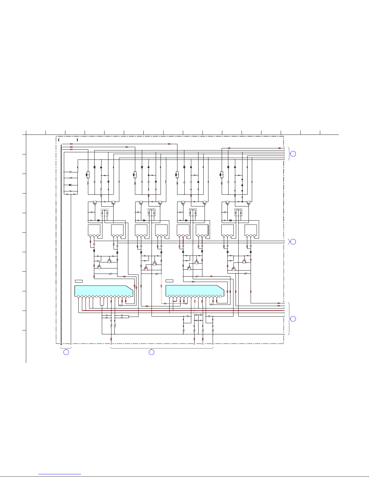
STR-DH720/DH720HP
STR-DH720/DH720HP
2727
5-14. SCHEMATIC DIAGRAM – MAIN Board (1/4) –
1
A
B
C
D
E
F
G
H
I
J
K
2 3 4 5 6 7 8 9 10 11 12 13 14 15 16
MAIN BOARD (1/4)
18 20 21 2219
1
2
3
4
5
6
7
8
9
10
12
13
14
15
16
11
17
-1
00
-60
0-1
-60
0
-1
-1
00
-60
0
-1
-1
00
-60
0
-1
-1
00
611 0 -61-1 0 611 0 -61-1 0 611 0 -61-1 0 611 0 -61-1 0
-1
0.4
-0.5
-1
0.4
-0.5
-1
0.4
-0.5
-1
0.4
-0.5
0.4
-1
1
0.4
-1
1
0.4
-1
1
0.4
-1
1
-61 61 61 1 00 0 0 0 -60 -1 1
-61 61 61 1 00 0 0 0 -60 -1 1
123456789101112131415
123
SBL_OUT
SBR_OUT
FR_OUT
R813
0.22
Q503
MN2488-OPY-MK
SBL +VE
47k
R830
R863
0.22
Q753
MN2488-OPY-MK
FR +VE
4.7k
R811
47k
R780
82k
R857
Q801
2SA1175-HFE
2SA1175-HFE
1.5k
R764
4.7k
R861
C870
0.01
Q504
MP1620-OPY-MK
SBL -VE
4.7k
R761
68k
R766
1.5k
R814
R779
10
15k
R815
Q754
MP1620-OPY-MK
FR -VE
1.5k
R864
C761
220p
C820
0.01
2.2k
R856
C879
0.022
2.2k
R756
68k
R804
Q854
MP1620-OPY-MK
C -VE
C861
220p
68k
R816
Q851
2SA1175-HFE
R879
10
2.2k
R806
R829
10
C779
0.022
82k
R757
R862
6.2k
15k
R865
68k
R866
47k
R880
R812
6.2k
15k
R765
R763
0.22
C770
0.01
82k
R807
Q853
MN2488-OPY
-MK
C +VE
C829
0.022
C811
220p
1k
R851
1k
R801
C852
100p
68k
R852
68k
R802
R760
100
R859
100
R809
100
R810
100
R860
100
R759
100
R762
6.2k
D536
MAZ8056GMLS0
22k
R548
22k
R549
100k
R772
100k
R822
100k
R872
68k
R854
2.2k
R853
47k
R820
47k
R870
0
R544
Q752
Q852
2SD2144S-V
Q802
2SD2144S-V
2SD2144S-V
1k
R560
C553
100p
68kR554
68k
R565
2.2k
R563
82k
R555
2.2k
R556
Q551
BIAS
BIAS
BIAS
BIAS
BIAS
Q751
2SA1175-HFE
BIAS
BIAS
2SD2144S-V
BIAS
R553
100
R567
100
Q552
Q554
MP1620-OPY-MK
SBR -VE
Q553
MN2488-OPY-MK
SBR +VE
BCE
123
BCE
123
BCE
123
BCE
123
BCE
123
BCE
123
BCE
123
BCE
R513
0.22
4.7k
R552
C554
0.01
L550
1.7uH
1.5k
R562
C550
0.022
C551
220p
R551
10
R558
6.2k
15k
R564
68k
R569
47k
R568
R550
4.7
L828
1.7uH
R828
4.7
L878
1.7uH
R878
4.7
L778
1.7uH
R778
4.7
100k
R559
47k
R557
C853
10p
C803
10p
C560
10p
C855
3p
C805
3p
C559
3p
C857
47 25V
C757
47 25V
C807
47 25V
C558
47 25V
C812
220
10V
C557
220
10V
C860
10
50V
C555
10
50V
560
R758
560
R858
560
R808
560
R566
C802
100p
C862
[SBL][SBR]
220
10V
C810
10
50V
2.2k
R803
6.8k
R547
47k
R770
C552
47p
C808
47p
C858
47p
C561
47p
C809
47p
C758
47p
C859
47p
C759
47p
Q862
2SA1514KT146S
Q811
2SA1514KT146S
Q762
2SA1514KT146S
Q555
2SA1514KT146S
Q861
2SA1514KT146S
Q812
2SA1514KT146S
Q761
2SA1514KT146S
Q550
CURRENT DETECT
CURRENT DETECT
CURRENT DETECT
CURRENT DETECT
CURRENT DETECT
CURRENT DETECT
CURRENT DETECT
CURRENT DETECT
2SA1514KT146S
IC801
STK350-630TS-E
MUTE
+VOUT1
-VOUT2
COMP1
NF1
IN1
GND
IN2
NF2
COMP2
-VOUT2
+VOUT2
VCC
VCC
VEE
IC501
STK350-630TS-E
MUTE
+VOUT1
-VOUT2
COMP1
NF1
IN1
GND
IN2
NF2
COMP2
-VOUT2
+VOUT2
VCC
VCC
VEE
D550
DA2J10100L
D551
DA2J10100L
D820
DA2J10100L
D811
DA2J10100L
D870
DA2J10100L
D861
DA2J10100L
D770
DA2J10100L
D761
DA2J10100L
C545
47 25V
C548
0.1
[FR][SBL][SBR]
[C]
[C]
123456789101112131415
SBR_OUT
C_OUT
SBL_OUT
PRE DRIVER
IC501
PRE DRIVER
IC801
CL394
CL395
CL396
CL397
1
MAIN BOARD
(2/4)
(Page 28)
3
MAIN BOARD
(2/4)
(Page 28)
4
MAIN BOARD (3/4)
(Page 29)
5
MAIN BOARD (3/4)
(Page 29)
2
MAIN BOARD
(2/4)
(Page 28)
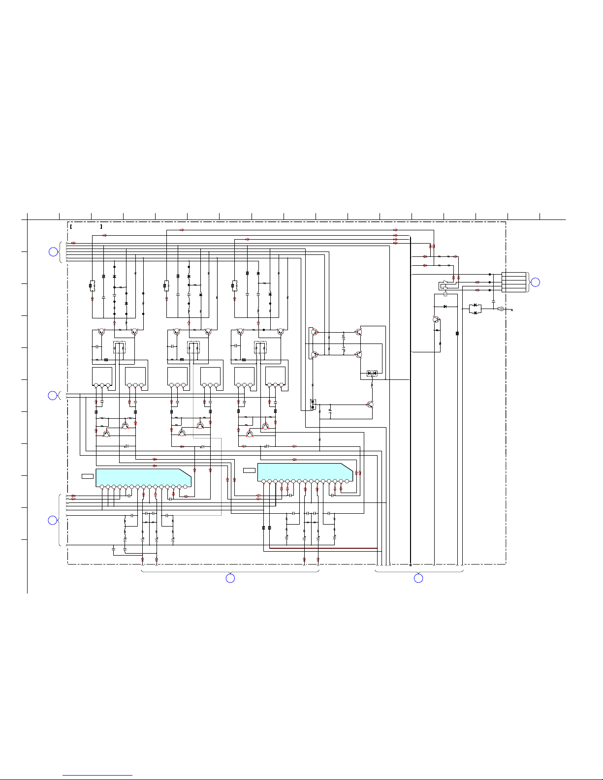
STR-DH720/DH720HP
STR-DH720/DH720HP
2828
5-15. SCHEMATIC DIAGRAM – MAIN Board (2/4) –
1
A
B
C
D
E
F
G
H
I
J
K
2 3 4 5 6 7 8 9 10 11 12 13 14 15 16 17
MAIN BOARD (2/4)
25 26
2423
27 28 29 30 32 33 34
1
2
3
4
5
6
7
8
9
10
12
13
14
15
16
11
31
(CHASSIS)
611 0
-61-1 0
611 0
-61-1 0 611 0
-61-1 0
-1
0.4
-0.5
0.4
-1
1
-1
0.4
-0.5
0.4
-1
1
-1
0.4
-0.5
0.4
-1
1
-60
0
-1
-1
00
-60
0
-1
-1
00
-60
0
-1
-1
00
0
0
3.3
3.3
0
0
-61
3.3
-61
0
-60
0
0
0
-60
0
15
-61 61 61 1 00 0 0 0 -60 -1 1
-61 61 61 1 00 0 0 0 -60 -1 1
E
2
3
4
5
SL_OUT
SR_OUT
HP
FR_OUT
FL_OUT
HP_DET
FL_OUT
Q653
MN2488-OPY-MK
SR +VE
R662
6.2k
47k
R680
2.2k
R656
1.5k
R664
C679
0.022
82k
R657
4.7k
R661
68k
R666
Q604
MP1620-OPY-MK
SL -VE
Q603
MN2488-OPY-MK
SL +VE
R679
10
Q654
MP1620-OPY-MK
SR -VE
15k
R665
R663
0.22
C670
0.01
C661
220p
Q701
1.5k
R714
C711
220p
Q703
MN2488-OPY-MK
FL +VE
R729
10
2.2k
R706
C720
0.01
82k
R707
4.7k
R711
C729
0.022
Q704
MP1620-OPY-MK
FL -VE
15k
R715
R713
0.22
R712
6.2k
68k
R716
39k
R326
Q324
2SC3052EF-T1-LEF
C325
10
50V
10k
R327
6.8k
R325
Q321
PROTECTOR
PROTECTOR
PROTECTOR
PROTECTOR
PROTECTOR
2SC3052EF-T1-LEF
1k
R328
1k
R601
C602
100p
1k
R651
C652
100p
68k
R652
1k
R751
1k
R701
C752
100p
C702
100p
68k
R752
68k
R702
2.2k
R375
Q375
RELA
Y DRIVER
2SC3052EF-T1-LEF
47k
R730
R709
100
R710
100
R660
100
R659
100
47k
R378
Q325
2SC2713-G
100k
R672
100k
R722
CL364
CL362
CL363
D327
MC2838-T112-1
D326
MC2838-T112-1
R610
100
82k
R607
R609
100
2.2k
R606
R613
0.22
C611
220p
R612
6.2k
4.7k
R611
1.5k
R614
100k
R622
C620
0.01
15k
R615
68k
R616
47k
R630
C629
0.022
R629
10
47k
R670
47k
R620
R545
0.47
R546
0.47
Q702
Q651
2SA1175-HFE
BIAS
2SA1175-HFE
BIAS
Q601
2SA1175-HFE
BIAS
Q652
2SD2144S-V
BIAS
2SD2144S-V
BIAS
Q602
2SD2144S-V
BIAS
123
BCE
L678
1.7uH
R678
4.7
L628
1.7uH
R628
4.7
L728
1.7uH
R728
4.7
68k
R602
C703
10p
C753
10p
C653
10p
C603
10p
C607
47 25V
C707
47 25V
C657
47 25V
C610
10
50V
C710
10
50V
C660
10
50V
C760
10
50V
560
R608
560
R708
560
R658
68k
R704
2.2k
R703
C705
3p
C712
220
10V
68k
R604
2.2k
R603
C605
3p
C612
220
10V
68k
R754
C755
3p
C762
220
10V
2.2k
R753
47k
R720
C658
47p
C708
47p
C608
47p
C659
47p
C609
47p
C709
47p
Q712
2SA1514KT146S
Q662
2SA1514KT146S
Q611
2SA1514KT146S
Q320
2SA1514KT146S
Q612
2SA1514KT146S
Q661
2SA1514KT146S
CURRENT DETECT
CURRENT DETECT
CURRENT DETECT
CURRENT DETECT
CURRENT DETECT
CURRENT
DETECT
Q711
2SA1514KT146S
Q323
2SA1514KT146S
IC601
STK350-630TS-E
MUTE
+VOUT1
-VOUT2
COMP1
NF1
IN1
GND
IN2
NF2
COMP2
-VOUT2
+VOUT2
VCC
VCC
VEE
IC701
STK350-630TS-E
MUTE
+VOUT1
-VOUT2
COMP1
NF1
IN1
GND
IN2
NF2
COMP2
-VOUT2
+VOUT2
VCC
VCC
VEE
ET300
CN391
5P
NC
1 HP DETECT
R-CH
GND
L-CH
D302
1SS367-T3SONY
D303
1SS367-T3SONY
D670
DA2J10100L
D661
DA2J10100L
D720
DA2J10100L
D711
DA2J10100L
D620
DA2J10100L
D611
DA2J10100L
D375
DA2J10100L
22k
R320
R321
22k
C320
220
10V
C321
220
10V
R377
82
C322
0.1
R392
330
330
R393
R394
330
330
R395
RY375
12V
1
2
3
4
5
6
[SR] [SL][FL]
[SL][SR]
[FL][FR]
68k
R654
C655
3p
C662
220
10V
2.2k
R653
123456789101112131415
123456789101112131415
123
BCE
123
BCE
123
BCE
123
BCE
123
BCE
SL_OUT
PROTECTOR
SR_OUT
PRE DRIVER
IC701
PRE DRIVER
IC601
CL401
CL398
CL387 CL385
CL386 CL384
CL399
CL400 CL391
CL390
CL383
CL388
CL389
H
HEADPHONE
BOARD
CN790
(Page 45)
6
MAIN BOARD (3/4)
(Page 29)
7
MAIN BOARD (4/4)
(Page 30)
3
MAIN
BOARD
(1/4)
(Page 27)
2
MAIN
BOARD
(1/4)
(Page 27)
1
MAIN
BOARD
(1/4)
(Page 27)
C403
10p
C404
10p
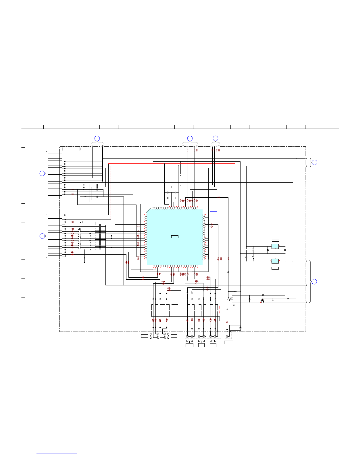
STR-DH720/DH720HP
STR-DH720/DH720HP
2929
5-16. SCHEMATIC DIAGRAM – MAIN Board (3/4) –
• See page 49 for IC Block Diagrams.
1
A
B
C
D
E
F
G
H
I
J
K
2 3 4 5 6 7 8 9 10 11 12 13 14 15 16 17
MAIN BOARD (3/4)
18
17
25 2620 21
22
2423
19
36
35
37
39
38
-15
-7
15
7
0 0 0 0 0 0 0 0 0 0 0 0 0 0 0 0 0 0
0
0
0
0
0
0
0
0
0
0
0
0
0
0
0
0
0
0
0
0
0
0
0
0
0
0
0
0
0
0
0
0
7 0
0 0
-7 0 0 0 0 0 0 0 0
0
0.7
IO
G
I
O
COM
G
1
2
3
4
5
6
7
8
9
10
11
12
13
14
15
16
17
18
2
3
4
5
6
7
8
9
10
11
12
13
14
15
16
17
18
19
DATA
CLK
SW
C_SUR
PROTECTOR
HP_DET
BRIDGE
SBL_R
LR
SW
HP
1kR451
1kR402
1kR452
C400
2200p
W002
CC01 100p
CC51 100p
CC02 100p
CC52 100p
CC08 100p
CC58 100p
CC03 100p
CC53 100p
CC05 100p
CC55 100p
1kR401
1k
R453
1k
R403
A_GND
C405
2200p
C449 100p
C450
100p
J405
D352
1SR154-400TE-25
C350
0.47
C352
0.47
RY301
2.2k
R301
100k
R467
47k
R304
47k
R470
C471
10
50V
1k
R466
1k
R455
1k
R405
1k
R408
C458
4.7
50V
C408
4.7
50V
1k
R458
0
R354
15k
R348
C547
10 50V
C546
10 50V
CL300
CL301
CL302
CL303
CL304
CL305
CL306
CL307
CL308
CL309
CL310
CL311
CL312
CL313
CL314
CL315
CL316
CL317
CL318
CL319
CL320
CL321
CL322
CL323
CL324
CL326
CL327
CL328
CL329
CL335
CL336
CL337
CL338
CL340
CL341
CL344
CL345
CL346
CL347
CL378
CL379
CL376
CL377
CL348
C489
2200p
C491
10p
C499
2200p
C490
10p
C488
0.1
CL325 CL392
CL382
CL381
CL333
C351
100
16V
C353
100
16V
220R450
220R449
1k
R357
C380
10 50V
C381
10 50V
C382
10 50V
C383
10 50V
C384
10 50V
C385
10 50V
C386
10 50V
C387
10 50V
1k
R380
1k
R381
1k
R382
1k
R383
1k
R384
1k
R385
1k
R386
1k
R387
220p
C388
C389 220p
1k
R388
1kR389
C390
3300p
C399
100p
C398
100p
C391
3300p
C392
3300p
C393
3300p
C394
3300p
C395
3300p
C396
3300p
C397
3300p
D301
DA2J10100L
GND
HPFN
LPF01
LPF02
LPFN2
LPFN1
SWVOL
VCC
DGND
DATA
CLK
VEE
FROUT
FLOUT
SWOUT
COUT
SROUT
SLOUT
SBROUT
SBLOUT
GND
GND
SUB2L
SUB2R
RECL3
RECR3
RECL2
RECR2
RECL1
RECR1
GND
SBL IN2
SBR IN2
SL IN2
SR IN2
C IN2
SW IN2
FL IN2
FR IN2
GND
INL12
INR12
INL11
INR11
INL10
INR10
INL9
INR9
INL8
INR8
INL7
INR7
INL6
INR6
INL5
INR5
INL4
INR4
INL3
INR3
INL2
INR2
INL1
INR1
GND
SBLIN
SBRIN
SLIN
SRIN
CIN
SWIN
FLIN
FRIN
GND
ADC ROUT
ADC LOUT
GND
SUB1 R
SUB1 L
GND
J409
2315476
J401
R302
100
C401
10p
C402
10p
CNP411
19P
+7V
NC
-7V
ADCL OUT
AGND
AGND
ADCR OUT
DAC FR IN
DAC FL IN
DAC SW
DAC C
DAC SR IN
DAC SL IN
DAC SBR IN
DAC SBL IN
DCAC
TUNER_R
TUNER_L
19
TUNER_L
CNP410
19P
NC
1+3.3V
DGND
REG_TEMP
HP_RY
PREOUT_SW_ RY
FL-FR_RY
SBL-R_RY
BRIDGEABLE_RY
C-SLR-RY
PROTECTOR
LIMITER
HP_DET
+15V_TUNER
EVOL_DATA
EVOL_CLK
VIDEO2_R
AGND
VIDEO2_L
2451 3 6789
10 11 12 13
14 15 16 17 18 19 20
59 57 5660 58 55 54 53 52
51 50 49 48
47 46 45 44 43 42 41
21
22
23
24
25
26
27
28
29
30
31
32
33
34
35
36
37
38
39
40
61
62
63
64
65
66
67
68
69
70
71
72
73
74
75
76
77
78
79
80
BD3470KS2
IC400
DIR FUNCTION SELECT
IC400
IC B/D
IC352
KIA7907PI
-7V REG
IC350
KIA7807API-U/PF
IC352
+7V REG
IC350
Q301
RELAY DRIVER
2SC3052EF-T1-LEF
L
R
SA-CD/CD
AUDIO IN
L
R
L R
SAT/CATV
AUDIO IN
L R
VIDEO 1
AUDIO OUT
L R
VIDEO 1
AUDIO IN
SUBWOOFER
AUDIO OUT
TV
AUDIO IN
F
DIGITAL
BOARD
(4/4)
CN2105
(Page 25)
G
DIGITAL
BOARD
(4/4)
CN2114
(Page 25)
9
MAIN BOARD
(4/4)
(Page 30)
4
MAIN BOARD (1/4)
(Page 27)
5
MAIN BOARD (1/4)
(Page 27)
6
MAIN BOARD (2/4)
(Page 28)
8
MAIN BOARD
(4/4)
(Page 30)
(ECE)
C323
10p
C324
10p
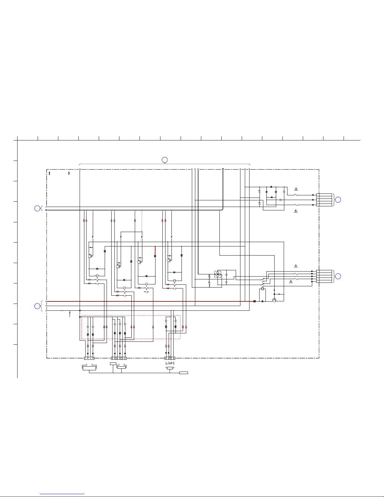
STR-DH720/DH720HP
STR-DH720/DH720HP
3030
5-17. SCHEMATIC DIAGRAM – MAIN Board (4/4) –
1
A
B
C
D
E
F
G
H
I
J
K
2 3 4 5 6 7 8 9 10 11 12 13 14 15 16 17
MAIN BOARD (4/4)
2728 29 323133 3430
36
35
37
39
38
1
2
3
4
5
SBL
SBR
SBL_R
SL_OUT
SR_OUT
C_SUR
C_OUT
LR
BRIDGE
FR_OUT
FL_OUT
C
SR
SL
FL
FR
RY920
1
2
3
5
6
8
4
7
2.2k
R921
Q920
RELAY DRIVER
2SC3052EF-T1-LEF
CNP920
5P
R1 (UPPER TAP)
R1 (LOWER TAP)
R1 GND
R1 (LOWER TAP)
R1 (UPPER TAP)
W001
Q360
RELAY DRIVER
2SC3052EF-T1-LEF
Q355
RELAY DRIVER
2SC3052EF-T1-LEF
Q365
RELAY DRIVER
2SC3052EF-T1-LEF
1k
R355
RR13
10
CC13
0.01
RR14
10
CC14
0.01
RR11
10
CC11
0.01
CC12
0.01
RR12
10
CC15
0.01
RR15
10
RR17
10
CC17
0.01
47k
R358
47k
R363
47k
R925
C911
0.1
C910
1SR154-400TE-25
D910 ~ D913
D912
D911
D910
D913
0.1
CL369
CL370
CL371
CL373
CL372
CL393
2.2k
R350
47k
R353
Q350
RELAY DRIVER
2SC3052EF-T1-LEF
F912
T6.3A 250V
F913
T6.3A 250V
47k
R366
1k
R367
RR18
10
CC18
0.01
CL356
CL357
CL358
CL359
CL360
CL361
CL355
JWH603
75
C912
2200
25V
C913
1000
25V
D921
D5SBA60-F
CL374
CL375
C932
0.1
C933
0.1
2.2k
R360
TB503
123456
TB502
1234
D350
DA2J10100L
D365
DA2J10100L
D355
DA2J10100L
D360
DA2J10100L
D920
DA2J10100L
2
3
4
5
CL366
CL367
CL368
F910
T2.5A 250V
F911
T2.5A 250V
CNP930
5P
NC
1
R2 AC
CENTER TAP
NC
R2 AC
C930
6800
71V
C931
6800
71V
R351
33
R365
33
R356
33
R361
33
R920
33
TB504
1
2345
RY360
12V
12
3
4
56
RY355
12V
12
3
4
56
RY365
12V
12
3
4
56
RY350
12V
12
3
4
56
SBR_OUT
SBL_OUT
++- -+--++-
SURROUND
R
L
FRONT
CENTER
L
R
-+ +-
SURROUND BACK/
FRONT HIGH
L
R
SPEAKERS
POWER
TRANSFORMER
(MAIN)
T901
(Page 38)
I
POWER
TRANSFORMER
(MAIN)
T901
(Page 38)
J
9
MAIN BOARD
(3/4)
(Page 29)
7
MAIN BOARD (2/4)
(Page 28)
8
MAIN BOARD
(3/4)
(Page 29)
(ECE)
 Loading...