


 Loading...
FLAT WIDE DISPLAY
FWD-42PV1 FWD-42PV1P FWD-42PV1A
REMOTE COMMANDER
RM-980
SPEAKER SYSTEM
SS-SP42FW
SERVICE MANUAL 1st Edition
! WARNING
This manual is intended for qualified service personnel only.
To reduce the risk of electric shock, fire or injury, do not perform any servicing other than that contained in the operating instructions unless you are qualified to do so. Refer all servicing to qualified service personnel.
! WARNUNG
Die Anleitung ist nur für qualifiziertes Fachpersonal bestimmt.
Alle Wartungsarbeiten dürfen nur von qualifiziertem Fachpersonal ausgeführt werden. Um die Gefahr eines elektrischen Schlages, Feuergefahr und Verletzungen zu vermeiden, sind bei Wartungsarbeiten strikt die Angaben in der Anleitung zu befolgen. Andere als die angegeben Wartungsarbeiten dürfen nur von Personen ausgeführt werden, die eine spezielle Befähigung dazu besitzen.
! AVERTISSEMENT
Ce manual est destiné uniquement aux personnes compétentes en charge de l’entretien. Afin de réduire les risques de décharge électrique, d’incendie ou de blessure n’effectuer que les réparations indiquées dans le mode d’emploi à moins d’être qualifié pour en effectuer d’autres. Pour toute réparation faire appel à une personne compétente uniquement.
FWD-42PV1/42PV1P/42PV1A
CAUTION
Danger of explosion if battery is incorrectly replaced.
Replace only with the same or equivalent type recommended by the manufacturer.
Dispose of used batteries according to the manufacturer’s instructions.
Vorsicht!
Explosionsgefahr bei unsachgemäß em Austausch der Batterie.
Ersatz nur durch denselben oder einen vom Hersteller empfohlenen ähnlichen Typ. Entsorgung gebrauchter Batterien nach Angaben des Herstellers.
ATTENTION
Il y a danger d’explosion s’il y a remplacement incorrect de la batterie.
Remplacer uniquement avec une batterie du même type ou d’un type équivalent recommandé par le constructeur.
Mettre au rebut les batteries usagées conformément aux instructions du fabricant.
For the customers in the Netherlands
Voor de klanten in Nederland
Hoe u de batterijen moet verwijderen, leest u in de tekst van deze handleiding.
Gooi de batterij niet weg maar lever deze in als klein chemisch afval (KCA).
FWD-42PV1/42PV1P/42PV1A
ADVARSEL!
Lithiumbatteri-Eksplosionsfare ved fejlagtig håndtering.
Udskiftning må kun ske med batteri af samme fabrikat og type.
Levér det brugte batteri tilbage til leverandø ren.
ADVARSEL
Lithiumbatteri - Eksplosjonsfare. Ved utskifting benyttes kun batteri som
anbefalt av apparatfabrikanten. Brukt batteri returneres apparatleverandø ren.
VARNING
Explosionsfara vid felaktigt batteribyte. Använd samma batterityp eller en likvärdig typ som rekommenderas av apparattillverkaren. Kassera använt batteri enligt gällande föreskrifter.
VAROITUS
Paristo voi räjähtää jos se on virheellisesti asennettu.
Vaihda paristo ainoastaan laitevalmistajan suosittelemaan tyyppiin.
Hävitä käytetty paristo valmistajan ohjeiden mukaisesti.
Für Kunden in Deutschland
Entsorgungshinweis: Bitte werfen Sie nur entladene Batterien in die Sammelboxen beim Handel oder den Kommunen. Entladen sind Batterien in der Regel dann, wenn das Gerät abschaltet und signalisiert “Batterie leer” oder nach längerer Gebrauchsdauer der Batterien “nicht mehr einwandfrei funktioniert”. Um sicherzugehen, kleben Sie die Batteriepole z.B. mit einem Klebestreifen ab oder geben Sie die Batterien einzeln in einen Plastikbeutel.
1 (P)
Table of Contents
1. |
Service Overview |
|
3. |
Troubleshooting |
|
|||
1-1. |
Appearance Figure .......................................................... |
1-1 |
3-1. |
Self Diagnosis Operation ................................................ |
3-1 |
|||
1-2. |
Board Location ............................................................... |
1-1 |
3-2. |
Check Point ..................................................................... |
3-1 |
|||
1-3. |
Disassembly .................................................................... |
1-2 |
3-2-1. |
A Board ................................................................. |
3-1 |
|||
1-3-1. |
Rear Cabinet Assembly ......................................... |
1-2 |
3-2-2. |
Plasma Display Panel ............................................ |
3-2 |
|||
1-3-2. |
Bezel Assembly/H1 Board/H2 Board ................... |
1-3 |
3-3. |
Image Trouble ................................................................. |
3-3 |
|||
1-3-3. |
A Board/L Board/I Board ...................................... |
1-4 |
3-4. |
Power (G Board) Trouble ............................................... |
3-4 |
|||
1-3-4. |
G Board/TEMP Board ........................................... |
1-5 |
3-5. |
Remote Control Trouble |
3-5 |
|||
|
|
|
|
|||||
1-3-5. |
T-R Board/T-L Board ............................................ |
1-5 |
3-6. |
Sound Trouble |
3-5 |
|||
1-3-6. |
A Block Assembly/DC Fan |
1-6 |
||||||
3-7. |
Other Trouble |
3-6 |
||||||
1-3-7. |
YDT Board/YDB Board |
1-7 |
||||||
3-8. |
Plasma Display Panel |
3-7 |
||||||
1-3-8. |
Y SUS Board |
1-7 |
||||||
3-8-1. |
Image is not displayed |
3-7 |
||||||
1-3-9. |
CTRL Board |
1-8 |
||||||
3-8-2. |
Vertical Image is abnormal |
3-8 |
||||||
1-3-10. |
Z SUS Board |
1-8 |
||||||
3-8-3. |
Horizontal Image is abnormal |
3-9 |
||||||
1-3-11. |
XL Board/XR Board |
1-9 |
||||||
3-8-4. |
Mal Discharge |
3-9 |
||||||
1-3-12. |
Plasma Display Panel |
1-10 |
||||||
|
|
|
|
|||||
1-4. |
Service Position ............................................................ |
1-11 |
|
|
|
|
||
1-4-1. |
Service Position of A Board ................................ |
1-11 |
4. |
Spare Parts |
|
|||
1-5. Packing of the Plasma Display Panel |
1-12 |
|
||||||
|
|
|
|
|||||
1-6. |
Warning on Power Connection ..................................... |
1-13 |
4-1. Notes on Repair Parts |
4-1 |
||||
|
|
|
|
|||||
1-7. |
Unleaded Solder ............................................................ |
1-13 |
4-2. |
Exploded Views |
4-2 |
|||
|
|
|
|
|||||
2. Service Mode and Adjustment |
|
5. |
Block Diagram |
|
||||
|
|
|
|
|
||||
2-1. |
Service Mode .................................................................. |
2-1 |
|
Overall |
5-1 |
|||
2-1-1. |
Service Mode Startup Procedure |
2-1 |
|
|||||
|
|
|
|
|||||
2-1-2. |
Configuration ........................................................ |
2-1 |
|
|
|
|
||
2-1-3. |
Description of Main Items ..................................... |
2-2 |
|
|
|
|
||
2-2. |
White Balance Adjustment ............................................. |
2-3 |
|
|
|
|
||
2-2-1. |
AD Calibration ...................................................... |
2-3 |
|
|
|
|
||
2-2-2. |
1PC Signal ............................................................. |
2-3 |
|
|
|
|
||
2-2-3. |
White Balance ....................................................... |
2-3 |
|
|
|
|
||
2-3. |
Va/Vs Voltage Adjustment ............................................. |
2-4 |
|
|
|
|
||
2-3-1. |
Required Equipment .............................................. |
2-4 |
|
|
|
|
||
2-3-2. |
Vs Voltage Adjustment ......................................... |
2-4 |
|
|
|
|
||
2-3-3. |
Va Voltage Adjustment ......................................... |
2-4 |
|
|
|
|
||
2-4. |
Vsc/_Vy Voltage Adjustment ........................................ |
2-4 |
|
|
|
|
||
2-4-1. |
Required Equipment .............................................. |
2-4 |
|
|
|
|
||
2-4-2. |
Vsc Voltage Adjustment ....................................... |
2-4 |
|
|
|
|
||
2-4-3. |
_Vy Voltage Adjustment ...................................... |
2-4 |
|
|
|
|
||
2-5. |
Firmware Version Upgrade ............................................ |
2-5 |
|
|
|
|
||
2-6. |
DEVICEINFO Section ................................................... |
2-5 |
|
|
|
|
||
FWD-42PV1/42PV1P/42PV1A |
1 |
Section 1
Service Overview
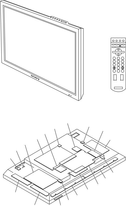
1-1. Appearance Figure
1 2 3
4 5 6
7 8 9
0
ON SET OFF
1-2. Board Location
I board
TEMP board
TEMP board
BKM-FW10
L board
G board Z SUS board
Y SUS board
H2 board
TEMP board
|
T-L board |
|
|
XR board |
|
|
A board |
|
YDT board |
CTRL board |
|
XL board |
||
|
||
|
T-R board |
|
YDB board |
H1 board |
FWD-42PV1/42PV1P/42PV1A |
1-1 |
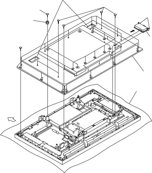
1-3. Disassembly
n
When removing/installing the cabinet and replacing the board, place the unit on the conductive cushion.
1-3-1. Rear Cabinet Assembly
7Hold the two handles and
remove the rear cabinet assembly.
6 Nineteen screws
3 Four screws
1 Panel securing
screws
4 Four knobs
2 BKM-FW10
5 Fourteen screws
8 Rear cabinet assembly
Conductive cushion
Upper side
1-2 |
FWD-42PV1/42PV1P/42PV1A |

1-3-2. Bezel Assembly/H1 Board/H2 Board
.Remove the rear cabinet assembly. (Refer to Section 1-3-1.)
m
.When removing the chassis assembly, be sure to work with more than two persons.
.When removing the chassis assembly, hold the four portions A and remove it from the front frame assembly.
.Place the removed chassis assembly on the conductive cushion.
Portions A
5 Chassis assembly
1 Four screws
9 Four screws |
|
|
Arm |
!- Two screws |
Portions A |
|
|
Arm |
2 Ten screws |
|
|
!= Control button bracket |
|
|
0 Front frame |
|
assembly |
!\ Control
button
!] H2 board
4 Filter glass

1-3-3. A Board/L Board/I Board
.Remove the rear cabinet assembly. (Refer to Section 1-3-1.)
CN15
CN8
CN9
CN29 CN1
CN23
CN19
CN3
CN22
CN501
!- A board
3 Two screws
4 I board
CN201
CN28
8 Four screws
1 Four screws
CN302
CN301
CN303
2 L board
Upper side
!= Removing the lithium battery.
Remove the lithium battery in the direction of the arrow.
Lithium battery (CR-1220)
Battery holder
9 Two screws
!/ Cover
!- A board
7 Interface cover
5 Six connector screws
6 Screw
Conductive cushion
1-4 |
FWD-42PV1/42PV1P/42PV1A |
1-3-4. G Board/TEMP Board
.Remove the rear cabinet assembly. (Refer to Section 1-3-1.)
|
CN8 |
CN800 |
CN808 |
|
|
CN802 |
|
|
|
CN807 |
CN805 |
1 Nine screws |
|
|
|
CN804 |
|
|
|
|
CN803 |
|
|
3 Screw |
|
CN801 |
|
2 G board |
|
|
|
|
||
|
|
|
P501 |
|
P501 |
|
|
|
|
5 Two screws |
|
|
|
4 TEMP board |
P501
Conductive cushion
6TEMP board
Upper side
1-3-5. T-R Board/T-L Board
.Remove the rear cabinet assembly. (Refer to Section 1-3-1.)
1 Three screws |
7 Option shield plate |
|
CN1304 |
5 Screws |
|
8 Two screws |
||
2 AC outlet cover |
||
CN1302 |
||
|
||
|
4 T-R board |
9 T-L board
6 Screw
3 Two screws
Conductive cushion
Upper side
FWD-42PV1/42PV1P/42PV1A |
1-5 |
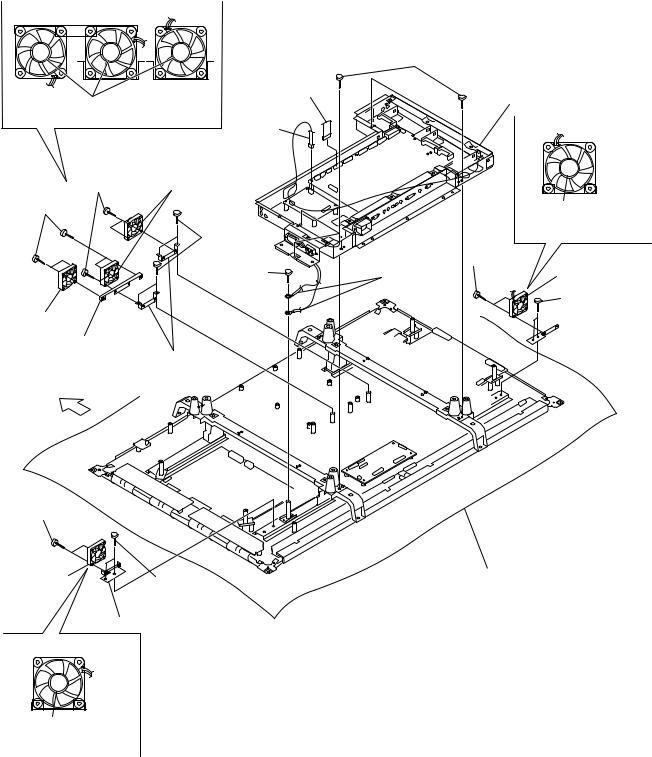
1-3-6. A Block Assembly/DC Fan
.Remove the rear cabinet assembly. (Refer to Section 1-3-1.)
.Remove the bezel assembly. (Refer to Section 1-3-2.)
.Remove the G board. (Refer to Section 1-3-4.)
DC fan installation direction
6 CN23
Make sure that the label is oriented in the
upward direction of the main unit.
1 CN302
!] Four screws !; DC fan
!- Four screws

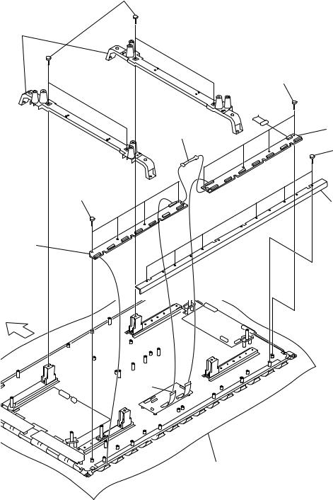
1-3-7. YDT Board/YDB Board
.Remove the rear cabinet assembly. (Refer to Section 1-3-1.)
.Remove the bezel assembly. (Refer to Section 1-3-2.)
.Remove the G board. (Refer to Section 1-3-4.)
6 Four screws |
5 Six screws |
7 YDT board
 P9
P9
8 YDB board
1 P10 Two screws
2 Speaker bracket |
|
3 Two screws |
support |
P21 |
P22 |
|
||
Upper side |
|
4 Support |
|
9 Harness |
|
|
P1 |
|
P2 |
|
P3 |
Conductive cushion |
P4 |
|
P5
P6
P7
P8
1-3-8. Y SUS Board
.Remove the rear cabinet assembly. (Refer to Section 1-3-1.)
.Remove the bezel assembly. (Refer to Section 1-3-2.)
.Remove the YDT board and YDB board. (Refer to Section 1-3-7.)
P5
P6
P3
P4
4 Three board brackets
Upper side |
3 Six screws |
|
1 Six screws
P8
2 Y SUS board
Conductive cushion
FWD-42PV1/42PV1P/42PV1A |
1-7 |

1-3-9. CTRL Board
.Remove the rear cabinet assembly. (Refer to Section 1-3-1.)
.Remove the bezel assembly. (Refer to Section 1-3-2.)
.Remove the A block assembly. (Refer to Section 1-3-6.)
2 Cushion retainer
|
1 Four screws |
|
P1 |
3 Cushion |
P10 |
P9
P4
P2
4 CTRL board
Upper side
Conductive cushion
1-3-10. Z SUS Board
.Remove the rear cabinet assembly. (Refer to Section 1-3-1.)
.Remove the bezel assembly. (Refer to Section 1-3-2.)
P1
1 Five screws
2 Z SUS board
Upper side
 P3
P3
P2
Conductive cushion
1-8 |
FWD-42PV1/42PV1P/42PV1A |
1-3-11. XL Board/XR Board
.Remove the rear cabinet assembly. (Refer to Section 1-3-1.)
.Remove the bezel assembly. (Refer to Section 1-3-2.)
.Remove the G board. (Refer to Section 1-3-4.)
.Remove the A block assembly. (Refer to Section 1-3-6.)
1 Four screws
2 Two frame modules
5 Four screws
6 XL board
Upper side
P4
P21
P22
7 Four screws
P3
9 Harness
P2
P5
P11
P1 |
P12 |
P13
P14
P15
P16
P17
P18
P19
P20
P23 |
Conductive cushion |
P24
8 XR board
3 Six screws
4 Flexible retainer
FWD-42PV1/42PV1P/42PV1A |
1-9 |
Loading...